EP3445492B1 - Puce microfluidique pour focaliser un courant de fluide contenant des particules - Google Patents
Puce microfluidique pour focaliser un courant de fluide contenant des particules Download PDFInfo
- Publication number
- EP3445492B1 EP3445492B1 EP17723635.3A EP17723635A EP3445492B1 EP 3445492 B1 EP3445492 B1 EP 3445492B1 EP 17723635 A EP17723635 A EP 17723635A EP 3445492 B1 EP3445492 B1 EP 3445492B1
- Authority
- EP
- European Patent Office
- Prior art keywords
- channel
- microfluidic
- fluid
- guidance
- chip
- Prior art date
- Legal status (The legal status is an assumption and is not a legal conclusion. Google has not performed a legal analysis and makes no representation as to the accuracy of the status listed.)
- Active
Links
- 239000012530 fluid Substances 0.000 title claims description 303
- 239000002245 particle Substances 0.000 claims description 198
- 238000001514 detection method Methods 0.000 claims description 106
- 238000000034 method Methods 0.000 claims description 61
- 230000005284 excitation Effects 0.000 claims description 39
- 238000004458 analytical method Methods 0.000 claims description 23
- 238000000926 separation method Methods 0.000 claims description 21
- 239000002131 composite material Substances 0.000 claims description 20
- 230000004044 response Effects 0.000 claims description 18
- 230000008859 change Effects 0.000 claims description 12
- 238000005086 pumping Methods 0.000 claims description 4
- 210000004027 cell Anatomy 0.000 description 216
- 239000000523 sample Substances 0.000 description 110
- 238000009652 hydrodynamic focusing Methods 0.000 description 51
- 230000003287 optical effect Effects 0.000 description 29
- 210000000582 semen Anatomy 0.000 description 29
- 238000005259 measurement Methods 0.000 description 18
- 238000000684 flow cytometry Methods 0.000 description 14
- 239000011324 bead Substances 0.000 description 13
- 238000010586 diagram Methods 0.000 description 12
- 230000000694 effects Effects 0.000 description 11
- 238000001566 impedance spectroscopy Methods 0.000 description 11
- 238000005304 joining Methods 0.000 description 11
- ZZUFCTLCJUWOSV-UHFFFAOYSA-N furosemide Chemical compound C1=C(Cl)C(S(=O)(=O)N)=CC(C(O)=O)=C1NCC1=CC=CO1 ZZUFCTLCJUWOSV-UHFFFAOYSA-N 0.000 description 10
- 238000004163 cytometry Methods 0.000 description 8
- 210000003743 erythrocyte Anatomy 0.000 description 8
- 238000002032 lab-on-a-chip Methods 0.000 description 8
- 239000007788 liquid Substances 0.000 description 8
- 241001465754 Metazoa Species 0.000 description 7
- 239000004793 Polystyrene Substances 0.000 description 7
- 229920002223 polystyrene Polymers 0.000 description 7
- 241000283690 Bos taurus Species 0.000 description 6
- 238000002474 experimental method Methods 0.000 description 6
- 239000000463 material Substances 0.000 description 6
- 238000012552 review Methods 0.000 description 6
- 230000004069 differentiation Effects 0.000 description 5
- 238000002347 injection Methods 0.000 description 5
- 239000007924 injection Substances 0.000 description 5
- 239000000203 mixture Substances 0.000 description 5
- 239000007787 solid Substances 0.000 description 5
- 239000000243 solution Substances 0.000 description 5
- 238000013459 approach Methods 0.000 description 4
- 238000000149 argon plasma sintering Methods 0.000 description 4
- 230000001186 cumulative effect Effects 0.000 description 4
- 208000037265 diseases, disorders, signs and symptoms Diseases 0.000 description 4
- 230000005684 electric field Effects 0.000 description 4
- 238000001917 fluorescence detection Methods 0.000 description 4
- 238000005194 fractionation Methods 0.000 description 4
- 230000005484 gravity Effects 0.000 description 4
- 241000894006 Bacteria Species 0.000 description 3
- 241000283086 Equidae Species 0.000 description 3
- 229910019142 PO4 Inorganic materials 0.000 description 3
- FAPWRFPIFSIZLT-UHFFFAOYSA-M Sodium chloride Chemical compound [Na+].[Cl-] FAPWRFPIFSIZLT-UHFFFAOYSA-M 0.000 description 3
- 238000013461 design Methods 0.000 description 3
- 201000010099 disease Diseases 0.000 description 3
- 210000002919 epithelial cell Anatomy 0.000 description 3
- 238000002847 impedance measurement Methods 0.000 description 3
- 230000002093 peripheral effect Effects 0.000 description 3
- NBIIXXVUZAFLBC-UHFFFAOYSA-K phosphate Chemical compound [O-]P([O-])([O-])=O NBIIXXVUZAFLBC-UHFFFAOYSA-K 0.000 description 3
- 239000010452 phosphate Substances 0.000 description 3
- 229920000642 polymer Polymers 0.000 description 3
- 239000011780 sodium chloride Substances 0.000 description 3
- 241000282472 Canis lupus familiaris Species 0.000 description 2
- 241000700198 Cavia Species 0.000 description 2
- 241000282326 Felis catus Species 0.000 description 2
- 241000699670 Mus sp. Species 0.000 description 2
- 241000700159 Rattus Species 0.000 description 2
- 230000002159 abnormal effect Effects 0.000 description 2
- 238000003556 assay Methods 0.000 description 2
- 210000002798 bone marrow cell Anatomy 0.000 description 2
- 210000000805 cytoplasm Anatomy 0.000 description 2
- 230000003247 decreasing effect Effects 0.000 description 2
- 238000005516 engineering process Methods 0.000 description 2
- 210000003494 hepatocyte Anatomy 0.000 description 2
- 230000006872 improvement Effects 0.000 description 2
- 208000014674 injury Diseases 0.000 description 2
- 230000010354 integration Effects 0.000 description 2
- 210000004962 mammalian cell Anatomy 0.000 description 2
- 239000012528 membrane Substances 0.000 description 2
- 229910052751 metal Inorganic materials 0.000 description 2
- 239000002184 metal Substances 0.000 description 2
- 150000002739 metals Chemical class 0.000 description 2
- 239000011859 microparticle Substances 0.000 description 2
- 239000002105 nanoparticle Substances 0.000 description 2
- 150000004767 nitrides Chemical class 0.000 description 2
- -1 oxides Chemical class 0.000 description 2
- 238000000206 photolithography Methods 0.000 description 2
- 230000035790 physiological processes and functions Effects 0.000 description 2
- 229920003229 poly(methyl methacrylate) Polymers 0.000 description 2
- 239000002861 polymer material Substances 0.000 description 2
- 239000004926 polymethyl methacrylate Substances 0.000 description 2
- 230000009467 reduction Effects 0.000 description 2
- 230000035945 sensitivity Effects 0.000 description 2
- 210000000130 stem cell Anatomy 0.000 description 2
- 150000003568 thioethers Chemical class 0.000 description 2
- 210000005167 vascular cell Anatomy 0.000 description 2
- 241000282421 Canidae Species 0.000 description 1
- 241000282693 Cercopithecidae Species 0.000 description 1
- 241000282994 Cervidae Species 0.000 description 1
- 241000699800 Cricetinae Species 0.000 description 1
- 241000283074 Equus asinus Species 0.000 description 1
- 241000233866 Fungi Species 0.000 description 1
- 241000282818 Giraffidae Species 0.000 description 1
- 241001272567 Hominoidea Species 0.000 description 1
- 208000002720 Malnutrition Diseases 0.000 description 1
- 241000124008 Mammalia Species 0.000 description 1
- 241000283973 Oryctolagus cuniculus Species 0.000 description 1
- 241000282579 Pan Species 0.000 description 1
- 241000282320 Panthera leo Species 0.000 description 1
- 241000282376 Panthera tigris Species 0.000 description 1
- 241001494479 Pecora Species 0.000 description 1
- 241000282405 Pongo abelii Species 0.000 description 1
- 241000288906 Primates Species 0.000 description 1
- 241000283984 Rodentia Species 0.000 description 1
- 241000295644 Staphylococcaceae Species 0.000 description 1
- 241000282887 Suidae Species 0.000 description 1
- 208000035896 Twin-reversed arterial perfusion sequence Diseases 0.000 description 1
- 241000700605 Viruses Species 0.000 description 1
- 208000027418 Wounds and injury Diseases 0.000 description 1
- 238000002679 ablation Methods 0.000 description 1
- 230000005856 abnormality Effects 0.000 description 1
- NIXOWILDQLNWCW-UHFFFAOYSA-N acrylic acid group Chemical group C(C=C)(=O)O NIXOWILDQLNWCW-UHFFFAOYSA-N 0.000 description 1
- 230000001580 bacterial effect Effects 0.000 description 1
- 230000008901 benefit Effects 0.000 description 1
- 230000000903 blocking effect Effects 0.000 description 1
- 210000003321 cartilage cell Anatomy 0.000 description 1
- 210000000170 cell membrane Anatomy 0.000 description 1
- 210000003855 cell nucleus Anatomy 0.000 description 1
- 238000012512 characterization method Methods 0.000 description 1
- 210000000349 chromosome Anatomy 0.000 description 1
- 238000004891 communication Methods 0.000 description 1
- 239000011246 composite particle Substances 0.000 description 1
- 238000010276 construction Methods 0.000 description 1
- 230000008878 coupling Effects 0.000 description 1
- 238000010168 coupling process Methods 0.000 description 1
- 238000005859 coupling reaction Methods 0.000 description 1
- 230000006378 damage Effects 0.000 description 1
- 230000001419 dependent effect Effects 0.000 description 1
- 238000005137 deposition process Methods 0.000 description 1
- 208000035475 disorder Diseases 0.000 description 1
- 238000009826 distribution Methods 0.000 description 1
- 230000005672 electromagnetic field Effects 0.000 description 1
- 230000007717 exclusion Effects 0.000 description 1
- 239000000835 fiber Substances 0.000 description 1
- 238000001914 filtration Methods 0.000 description 1
- 239000012634 fragment Substances 0.000 description 1
- 230000002538 fungal effect Effects 0.000 description 1
- 239000011521 glass Substances 0.000 description 1
- PCHJSUWPFVWCPO-UHFFFAOYSA-N gold Chemical compound [Au] PCHJSUWPFVWCPO-UHFFFAOYSA-N 0.000 description 1
- 239000010931 gold Substances 0.000 description 1
- 229910052737 gold Inorganic materials 0.000 description 1
- 230000036541 health Effects 0.000 description 1
- 210000004408 hybridoma Anatomy 0.000 description 1
- 238000005286 illumination Methods 0.000 description 1
- 210000002865 immune cell Anatomy 0.000 description 1
- 230000001771 impaired effect Effects 0.000 description 1
- 208000015181 infectious disease Diseases 0.000 description 1
- 239000011147 inorganic material Substances 0.000 description 1
- 238000011835 investigation Methods 0.000 description 1
- 238000002955 isolation Methods 0.000 description 1
- 210000003292 kidney cell Anatomy 0.000 description 1
- 210000000265 leukocyte Anatomy 0.000 description 1
- 210000000207 lymphocyte subset Anatomy 0.000 description 1
- 206010025482 malaise Diseases 0.000 description 1
- 238000004519 manufacturing process Methods 0.000 description 1
- 210000002569 neuron Anatomy 0.000 description 1
- 210000004940 nucleus Anatomy 0.000 description 1
- 235000018343 nutrient deficiency Nutrition 0.000 description 1
- 239000011368 organic material Substances 0.000 description 1
- 230000003071 parasitic effect Effects 0.000 description 1
- 230000007170 pathology Effects 0.000 description 1
- 239000004033 plastic Substances 0.000 description 1
- 229920003023 plastic Polymers 0.000 description 1
- 231100000572 poisoning Toxicity 0.000 description 1
- 230000000607 poisoning effect Effects 0.000 description 1
- 230000010287 polarization Effects 0.000 description 1
- 238000012545 processing Methods 0.000 description 1
- 230000002685 pulmonary effect Effects 0.000 description 1
- 238000004451 qualitative analysis Methods 0.000 description 1
- 238000004445 quantitative analysis Methods 0.000 description 1
- 238000013341 scale-up Methods 0.000 description 1
- 238000000790 scattering method Methods 0.000 description 1
- 238000004513 sizing Methods 0.000 description 1
- 210000004927 skin cell Anatomy 0.000 description 1
- 238000004611 spectroscopical analysis Methods 0.000 description 1
- 238000010186 staining Methods 0.000 description 1
- 238000001356 surgical procedure Methods 0.000 description 1
- 239000000725 suspension Substances 0.000 description 1
- 208000024891 symptom Diseases 0.000 description 1
- 208000011580 syndromic disease Diseases 0.000 description 1
- 230000009261 transgenic effect Effects 0.000 description 1
- 230000008733 trauma Effects 0.000 description 1
- XLYOFNOQVPJJNP-UHFFFAOYSA-N water Substances O XLYOFNOQVPJJNP-UHFFFAOYSA-N 0.000 description 1
Images


Classifications
-
- B—PERFORMING OPERATIONS; TRANSPORTING
- B01—PHYSICAL OR CHEMICAL PROCESSES OR APPARATUS IN GENERAL
- B01L—CHEMICAL OR PHYSICAL LABORATORY APPARATUS FOR GENERAL USE
- B01L3/00—Containers or dishes for laboratory use, e.g. laboratory glassware; Droppers
- B01L3/50—Containers for the purpose of retaining a material to be analysed, e.g. test tubes
- B01L3/502—Containers for the purpose of retaining a material to be analysed, e.g. test tubes with fluid transport, e.g. in multi-compartment structures
- B01L3/5027—Containers for the purpose of retaining a material to be analysed, e.g. test tubes with fluid transport, e.g. in multi-compartment structures by integrated microfluidic structures, i.e. dimensions of channels and chambers are such that surface tension forces are important, e.g. lab-on-a-chip
- B01L3/502769—Containers for the purpose of retaining a material to be analysed, e.g. test tubes with fluid transport, e.g. in multi-compartment structures by integrated microfluidic structures, i.e. dimensions of channels and chambers are such that surface tension forces are important, e.g. lab-on-a-chip characterised by multiphase flow arrangements
- B01L3/502776—Containers for the purpose of retaining a material to be analysed, e.g. test tubes with fluid transport, e.g. in multi-compartment structures by integrated microfluidic structures, i.e. dimensions of channels and chambers are such that surface tension forces are important, e.g. lab-on-a-chip characterised by multiphase flow arrangements specially adapted for focusing or laminating flows
-
- B—PERFORMING OPERATIONS; TRANSPORTING
- B01—PHYSICAL OR CHEMICAL PROCESSES OR APPARATUS IN GENERAL
- B01L—CHEMICAL OR PHYSICAL LABORATORY APPARATUS FOR GENERAL USE
- B01L3/00—Containers or dishes for laboratory use, e.g. laboratory glassware; Droppers
- B01L3/50—Containers for the purpose of retaining a material to be analysed, e.g. test tubes
- B01L3/502—Containers for the purpose of retaining a material to be analysed, e.g. test tubes with fluid transport, e.g. in multi-compartment structures
- B01L3/5027—Containers for the purpose of retaining a material to be analysed, e.g. test tubes with fluid transport, e.g. in multi-compartment structures by integrated microfluidic structures, i.e. dimensions of channels and chambers are such that surface tension forces are important, e.g. lab-on-a-chip
- B01L3/502746—Containers for the purpose of retaining a material to be analysed, e.g. test tubes with fluid transport, e.g. in multi-compartment structures by integrated microfluidic structures, i.e. dimensions of channels and chambers are such that surface tension forces are important, e.g. lab-on-a-chip characterised by the means for controlling flow resistance, e.g. flow controllers, baffles
-
- B—PERFORMING OPERATIONS; TRANSPORTING
- B01—PHYSICAL OR CHEMICAL PROCESSES OR APPARATUS IN GENERAL
- B01L—CHEMICAL OR PHYSICAL LABORATORY APPARATUS FOR GENERAL USE
- B01L3/00—Containers or dishes for laboratory use, e.g. laboratory glassware; Droppers
- B01L3/50—Containers for the purpose of retaining a material to be analysed, e.g. test tubes
- B01L3/502—Containers for the purpose of retaining a material to be analysed, e.g. test tubes with fluid transport, e.g. in multi-compartment structures
- B01L3/5027—Containers for the purpose of retaining a material to be analysed, e.g. test tubes with fluid transport, e.g. in multi-compartment structures by integrated microfluidic structures, i.e. dimensions of channels and chambers are such that surface tension forces are important, e.g. lab-on-a-chip
- B01L3/502761—Containers for the purpose of retaining a material to be analysed, e.g. test tubes with fluid transport, e.g. in multi-compartment structures by integrated microfluidic structures, i.e. dimensions of channels and chambers are such that surface tension forces are important, e.g. lab-on-a-chip specially adapted for handling suspended solids or molecules independently from the bulk fluid flow, e.g. for trapping or sorting beads, for physically stretching molecules
-
- C—CHEMISTRY; METALLURGY
- C12—BIOCHEMISTRY; BEER; SPIRITS; WINE; VINEGAR; MICROBIOLOGY; ENZYMOLOGY; MUTATION OR GENETIC ENGINEERING
- C12M—APPARATUS FOR ENZYMOLOGY OR MICROBIOLOGY; APPARATUS FOR CULTURING MICROORGANISMS FOR PRODUCING BIOMASS, FOR GROWING CELLS OR FOR OBTAINING FERMENTATION OR METABOLIC PRODUCTS, i.e. BIOREACTORS OR FERMENTERS
- C12M47/00—Means for after-treatment of the produced biomass or of the fermentation or metabolic products, e.g. storage of biomass
- C12M47/04—Cell isolation or sorting
-
- G—PHYSICS
- G01—MEASURING; TESTING
- G01N—INVESTIGATING OR ANALYSING MATERIALS BY DETERMINING THEIR CHEMICAL OR PHYSICAL PROPERTIES
- G01N15/00—Investigating characteristics of particles; Investigating permeability, pore-volume or surface-area of porous materials
- G01N15/10—Investigating individual particles
- G01N15/14—Optical investigation techniques, e.g. flow cytometry
- G01N15/1404—Handling flow, e.g. hydrodynamic focusing
-
- G—PHYSICS
- G01—MEASURING; TESTING
- G01N—INVESTIGATING OR ANALYSING MATERIALS BY DETERMINING THEIR CHEMICAL OR PHYSICAL PROPERTIES
- G01N15/00—Investigating characteristics of particles; Investigating permeability, pore-volume or surface-area of porous materials
- G01N15/10—Investigating individual particles
- G01N15/14—Optical investigation techniques, e.g. flow cytometry
- G01N15/1456—Optical investigation techniques, e.g. flow cytometry without spatial resolution of the texture or inner structure of the particle, e.g. processing of pulse signals
- G01N15/1459—Optical investigation techniques, e.g. flow cytometry without spatial resolution of the texture or inner structure of the particle, e.g. processing of pulse signals the analysis being performed on a sample stream
-
- G—PHYSICS
- G01—MEASURING; TESTING
- G01N—INVESTIGATING OR ANALYSING MATERIALS BY DETERMINING THEIR CHEMICAL OR PHYSICAL PROPERTIES
- G01N15/00—Investigating characteristics of particles; Investigating permeability, pore-volume or surface-area of porous materials
- G01N15/10—Investigating individual particles
- G01N15/14—Optical investigation techniques, e.g. flow cytometry
- G01N15/1484—Optical investigation techniques, e.g. flow cytometry microstructural devices
-
- B—PERFORMING OPERATIONS; TRANSPORTING
- B01—PHYSICAL OR CHEMICAL PROCESSES OR APPARATUS IN GENERAL
- B01L—CHEMICAL OR PHYSICAL LABORATORY APPARATUS FOR GENERAL USE
- B01L2200/00—Solutions for specific problems relating to chemical or physical laboratory apparatus
- B01L2200/06—Fluid handling related problems
- B01L2200/0636—Focussing flows, e.g. to laminate flows
-
- B—PERFORMING OPERATIONS; TRANSPORTING
- B01—PHYSICAL OR CHEMICAL PROCESSES OR APPARATUS IN GENERAL
- B01L—CHEMICAL OR PHYSICAL LABORATORY APPARATUS FOR GENERAL USE
- B01L2200/00—Solutions for specific problems relating to chemical or physical laboratory apparatus
- B01L2200/06—Fluid handling related problems
- B01L2200/0647—Handling flowable solids, e.g. microscopic beads, cells, particles
- B01L2200/0652—Sorting or classification of particles or molecules
-
- B—PERFORMING OPERATIONS; TRANSPORTING
- B01—PHYSICAL OR CHEMICAL PROCESSES OR APPARATUS IN GENERAL
- B01L—CHEMICAL OR PHYSICAL LABORATORY APPARATUS FOR GENERAL USE
- B01L2300/00—Additional constructional details
- B01L2300/06—Auxiliary integrated devices, integrated components
- B01L2300/0627—Sensor or part of a sensor is integrated
- B01L2300/0645—Electrodes
-
- B—PERFORMING OPERATIONS; TRANSPORTING
- B01—PHYSICAL OR CHEMICAL PROCESSES OR APPARATUS IN GENERAL
- B01L—CHEMICAL OR PHYSICAL LABORATORY APPARATUS FOR GENERAL USE
- B01L2300/00—Additional constructional details
- B01L2300/06—Auxiliary integrated devices, integrated components
- B01L2300/0627—Sensor or part of a sensor is integrated
- B01L2300/0663—Whole sensors
-
- B—PERFORMING OPERATIONS; TRANSPORTING
- B01—PHYSICAL OR CHEMICAL PROCESSES OR APPARATUS IN GENERAL
- B01L—CHEMICAL OR PHYSICAL LABORATORY APPARATUS FOR GENERAL USE
- B01L2300/00—Additional constructional details
- B01L2300/08—Geometry, shape and general structure
- B01L2300/0861—Configuration of multiple channels and/or chambers in a single devices
-
- B—PERFORMING OPERATIONS; TRANSPORTING
- B01—PHYSICAL OR CHEMICAL PROCESSES OR APPARATUS IN GENERAL
- B01L—CHEMICAL OR PHYSICAL LABORATORY APPARATUS FOR GENERAL USE
- B01L2400/00—Moving or stopping fluids
- B01L2400/04—Moving fluids with specific forces or mechanical means
- B01L2400/0403—Moving fluids with specific forces or mechanical means specific forces
- B01L2400/0463—Hydrodynamic forces, venturi nozzles
-
- B—PERFORMING OPERATIONS; TRANSPORTING
- B01—PHYSICAL OR CHEMICAL PROCESSES OR APPARATUS IN GENERAL
- B01L—CHEMICAL OR PHYSICAL LABORATORY APPARATUS FOR GENERAL USE
- B01L2400/00—Moving or stopping fluids
- B01L2400/04—Moving fluids with specific forces or mechanical means
- B01L2400/0403—Moving fluids with specific forces or mechanical means specific forces
- B01L2400/0469—Buoyancy
-
- G—PHYSICS
- G01—MEASURING; TESTING
- G01N—INVESTIGATING OR ANALYSING MATERIALS BY DETERMINING THEIR CHEMICAL OR PHYSICAL PROPERTIES
- G01N15/00—Investigating characteristics of particles; Investigating permeability, pore-volume or surface-area of porous materials
- G01N2015/0038—Investigating nanoparticles
-
- G—PHYSICS
- G01—MEASURING; TESTING
- G01N—INVESTIGATING OR ANALYSING MATERIALS BY DETERMINING THEIR CHEMICAL OR PHYSICAL PROPERTIES
- G01N15/00—Investigating characteristics of particles; Investigating permeability, pore-volume or surface-area of porous materials
- G01N2015/0042—Investigating dispersion of solids
- G01N2015/0053—Investigating dispersion of solids in liquids, e.g. trouble
-
- G—PHYSICS
- G01—MEASURING; TESTING
- G01N—INVESTIGATING OR ANALYSING MATERIALS BY DETERMINING THEIR CHEMICAL OR PHYSICAL PROPERTIES
- G01N15/00—Investigating characteristics of particles; Investigating permeability, pore-volume or surface-area of porous materials
- G01N15/10—Investigating individual particles
- G01N2015/1006—Investigating individual particles for cytology
-
- G—PHYSICS
- G01—MEASURING; TESTING
- G01N—INVESTIGATING OR ANALYSING MATERIALS BY DETERMINING THEIR CHEMICAL OR PHYSICAL PROPERTIES
- G01N15/00—Investigating characteristics of particles; Investigating permeability, pore-volume or surface-area of porous materials
- G01N15/10—Investigating individual particles
- G01N15/14—Optical investigation techniques, e.g. flow cytometry
- G01N2015/1402—Data analysis by thresholding or gating operations performed on the acquired signals or stored data
-
- G—PHYSICS
- G01—MEASURING; TESTING
- G01N—INVESTIGATING OR ANALYSING MATERIALS BY DETERMINING THEIR CHEMICAL OR PHYSICAL PROPERTIES
- G01N15/00—Investigating characteristics of particles; Investigating permeability, pore-volume or surface-area of porous materials
- G01N15/10—Investigating individual particles
- G01N15/14—Optical investigation techniques, e.g. flow cytometry
- G01N15/1404—Handling flow, e.g. hydrodynamic focusing
- G01N2015/1413—Hydrodynamic focussing
Definitions
- the invention relates to a microfluidic chip and method for focussing a stream of particulate containing fluid and optionally analysing the focussed stream of particulate containing fluid.
- the microfluidic chip is for impedance spectroscopy or optical scattering based analysis, identification or separation of particulate containing fluids.
- the microfluidic chip is for impedance spectroscopy or optical scattering or fluorescence based analysis, identification or separation of cell containing fluids, especially fluids containing different sub-populations of cells.
- the term “particles” or “particulates” will be used to describe solid particles, e.g. particles of metals, oxides, nitrides, sulphides, polymer particles and particles of numerous other inorganic and organics materials, also mixed particles containing blends and composites of materials within individual particles and various nano- and micro-particles and clusters, semi-solid particles such as jells.
- the term will also be used to describe soft particles e.g. polystyrene beads and acrylic beads or indeed blends of soft particles and their compositions, blends and compositions involving soft matter materials and solid matter materials in each particle.
- the term will also be used to describe cells, e.g. mammalian cells and/or any other cells.
- the particle is a contained object whose properties differ from those of the liquid carrying it.
- a stream of particles or cells is positioned within a detection zone that sometimes is also called "flow cell", by applying a stream of sheath fluid, which surrounds the stream of particulate containing fluid and coaxially focuses the sample stream to achieve uniform flow of cell passing the detector one-by-one.
- the flow rate of the sheath stream is one-to-two orders of magnitude greater than of the sample stream to achieve appropriate focusing ratio and obtain the sample stream of 30-70 micrometers in diameter that is a suitable size for the optical-detection-based cytometers.
- flowing cells or particles pass through a focused laser beam inside the detection channel and scattering of laser light is measured.
- Two directions of light scattering are detected independently: forward light scattering, which contains information about the particles size and side light scattering, which contains information about internal properties of the cell or particles. Additionally, side light scattering signal might be subject to light filtering in order to extract information about certain fluorescence emission bands of the particle or cell. It is important to note that hydrodynamic focusing is necessary to reduce variation of scattered light signal by making sure that all particles or cells are subjected to the same intensity of laser light and pass through the focused laser beam uniformly. Uniformity implies uniformity of the trace of the cells or particles in the focused laser beam as this affects the intensity of the detected signal. If the particles or cells are not of circular shape as they often are, uniformity also refers to of their orientation with respect to the focused beam direction. Indeed if the cells are e.g. discoid, then the optical signal will change depending on whether they face the optical beam facing with larger area side (flat face) or smaller area side (edge of the discoid).
- Particles or cells then can be divided into subpopulations based on their respective fluorescence intensities in a certain fluorescence band. These subpopulations could correspond to respective staining of particular cell receptors, cytoplasm or nucleus. It is becoming more important to differentiate particles or cells, which differ by minute change of particular cell properties. For example, accurate measurement of cell size allows detecting abnormal red blood cells amongst healthy red blood cells. Ability to differentiate cell shape allows detection of sickle cells and for differentiation of different types of bacteria, for example rod shaped E-coli or circular shaped Staphylococci bacteria. Measurement of content of the cell nucleus allows for example for differentiation of X and Y bearing chromosomes in spermatozoa cells. Such measurements of minute difference of these cell properties are beyond current advancements in conventional flow cytometry. The main limitation preventing more accurate measurements is inability of current techniques to present all the cells or particles in the particulate fluid in front of the detector in a reproducible and accurate manner.
- Microfluidics provides a convenient technology platform to miniaturize conventional scattering flow cytometry making construction and manufacturing of conventional flow cytometry detection channel simple, miniature while also making the whole device disposable.
- microfluidic flow cytometers utilizing fluorescence and impedance detection on chip in order to count the cells and to evaluate cell properties.
- article "Microflow cytometer with integrated hydrodynamic focusing” describes several configurations of integrated cytometer on microfluidic chip including hydrodynamic focusing and also describes experiments with fluorescence detection of calibration beads with various fluorescent intensities. The method provided allows for low CV of measurements for intensity of particles around 3%, which is comparable with conventional flow cytometry measurements.
- authors have experimented with detection of fluorescently tagged lymphocyte subpopulation, with results comparable with those of conventional cytometry.
- the inventors have also investigated impedance flow spectroscopy method of cell detection where two pairs of electrodes are used similar to configuration described in [10], each pair having an excitation and measurement electrodes.
- An AC voltage at radio frequency from 100 KHz -100 MHz is applied to an excitation electrodes and an electrical current is measured by the measurement electrodes.
- the electrical current being measured is then amplified and converted into an output voltage.
- the output signal is then demodulated to remove excitation frequency and to recover impedance magnitude and phase.
- impedance magnitude and phase change, thus recording the information about the cell properties. Additional pair of electrodes ensures measurement is differential thus eliminating parasitic electromagnetic noise.
- the measurement is taken at low frequency: 200KHZ-500KHZ to acquire information about the cell size and at high frequency 2-50MHz to acquire information about the cytoplasm and internal properties of the cell.
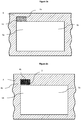
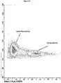
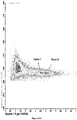
- Figure 1a displays density plot of impedance magnitude versus phase for a population of identical polystyrene beads.
- the beads are polystyrene beads of 6 ⁇ m in diameter.
- the channel is of a square cross-section (30 ⁇ m x 30 ⁇ m) and there are two electrodes deposited on the channel with the size of 20 ⁇ m x 0.2 ⁇ m: the top electrode deposited on the upper wall of the channel (ceiling of the channel) is the excitation electrode and the electrode at the lower wall of the channel (floor of the channel) is the detection electrode.
- Fig. 1a plots this data for a fluid containing the polystyrene beads in the format of magnitude vs phase that is convenient for further discussion.
- the impedance signal depends on the cell size and also on the cell position within the microfluidic channel.
- signal is different for the cells flowing at the top of the channel and close to excitation electrode versus those flowing at the bottom of the channel and close to measurement electrode.
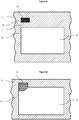
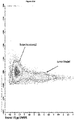
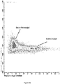
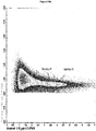
- figure 1b displays the scatter of the data points from a population of red blood cells in the same format of impedance magnitude versus impedance phase. We shall refer to this format of data presentation as impedance density plot.
- This ordering occurs due to four lateral forces acting on the particle flowing in the rectangular walled channel: Magnus force due to slip-rotation, Saffman force due to slip-shear, wall lift force due to the disturbance of flow field around particles from wall, and shear gradient lift force due to the parabolic curvature of the undisturbed velocity profile [2].
- Hydrodynamic focusing is particularly important for the detection of cells and particles on a chip utilizing impedance measurements. Indeed, for identification of cells (or particles) it is necessary to arrange these in such a flow that they pass in front of the detection system one by one.
- This "one cell-by-one cell” principle is fundamental for the successful cell identification: one needs to avoid the situation of multiple cells passing through the detection system at once as it could prevent the identification.
- Making the channel so small that cells (particles) align there one by one due to the tight cross-section of the channel is not practical: such a small channel that is comparable in cross-section with a single cell, is prone to blockage and it would also require a significant pressure difference as the friction of the laminar flow against the walls increases with decreasing channel cross-section.
- Hydrodynamic focusing is based on injection of the sample fluid into the laminar flow of sheath fluid. The two flows then merge into to a single channel, usually of a reduced cross-section. This reduces the cross-sections of both, the sheath fluid part of the flow and also the sample liquid flow, and thus achieves the desired reduction in the cross-section of the sample fluid flow.
- To control the cross-section of the sample fluid one could change the flow rates of the sample fluid and sheath fluid. For example, the flow rate of the sheath fluid could be increased to reduce the cross-section of the sample fluid.
- Such a small cross-section of the sample fluid flanked by the flow of the sheath fluid passes through a channel of a rather large cross-section, i.e. multiple of the cell size, that does not block.
- microfluidic focusing replaces the hard walls of microfluidic channel for fluid quasi-walls and this reduces the risk of the microchannel blocking.
- hydrodynamic focussing reduces the width of the conductive sample stream to the appropriate size of the cells, increasing the percentage resistance change in the conductive path when a cell passes by.
- microfluidic impedance cytometry has been further developed to count and discriminate between different kinds of cells.
- Multi-frequency impedance measurements can be used to determine the electrical properties of single cells in a microchip [ S. Gawad, L. Schild, P.H. Renaud, Micromachined impedance spectroscopy flow cytometer for cell analysis and particle sizing, Lab. Chip. 2001 1 76-82 ;
- the sample flow through a well-defined point in between the electrodes, e.g. the center of the channel. This reduces the spread in the data points from a single population of cells of type of particles in the flow. It may also be desirable to align all the cells (particles) in the same way with respect to the direction of the electric field created by the electrodes. Cells often do not have an overall spherical shape but are rather elongated, ellipsoidal or discoid in shape. The signal from the cell in electrical impedance cytometry device depends on the orientation of the elongated axis of the cell with respect to the electrodes.
- the Japanese patent laid-open No 2003-107099 discloses a "fractionation microchip having a channel for introducing a particulate-containing solution, and a sheath flow forming channel arranged on at least one lateral side of the of the introducing channel.
- the fractionation microchip further has "a particulate measuring section for measuring the particulates introduced, at least two particulate fractionating channels disposed on the downstream side of the particulate measuring section so as to perform fractional collection of the particulates, and at least two electrodes disposed in the vicinity of channel ports opening ...
- the particulate fractionation microchip disclosed in Patent 2003-107099 is so designed that fluid laminar flows are formed by a "trifurcated channel" having a channel for introducing a particulate-containing solution and two sheath flow-forming channels. In essence this is a 2D hydrodynamic focussing on a chip.
- the trifurcated channel ensures that the particulate-containing solution is sandwiched by the flows of the sheath liquid from the left and right sides, and the particulates are made to flow through the center of the channel in the particulate measuring section.
- each of the particulates can be accurately irradiated with measuring light. Similar approach is described in [ R. Rodriguez-Trujillo, C. Mills, J. Samitier, G. Gomila, Microfluid. Nanofluid, 3 171 (2007 )] and [ P.Walsh, E. Walsh, M. Davies, Int. J. Heat Fluid Flow 28 44 (2007 )].
- the 2D hydrodynamic focussing has its intrinsic limitations. With this in mind, there is an increased effort to introduce a 3D hydrodynamic focussing on a microfluidic chip to confine the sample in both, the horizontal and vertical directions.
- One solution for integration of such 3D focussing with a conventional type microfluidic chip is described in [" Three-dimensional hydrodynamic focussing in a microfluidic Coulter counter", R. Scott, P. Sethu, C.K. Harnett, Rev. Sci. Instruments 79 046104 (2008 )].
- the focussing is achieved in using a two-level design, the sheath fluid enters the microfluidic chip from a channel that is both, wider and taller than the sample stream.
- 3D focussing refers to the confinement of sample flow to a straight line at the centre of a channel of a conventional microfluidic planar chip.
- the authors of that publication state that "particles have a tendency to settle in positions away from the centre of the channel. The flow focussing needs to counter such effects". Therefore, the trend in the microfluidic devices is to position particles at the centre of the microfluidic channel.
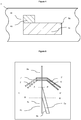
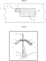
- Shinoda et. al. [8] teaches of the method of three dimensional hydrodynamic focusing where the microtube is inserted into the microchip to providing the sample flow.
- the microchip is constructed in such a way that the sheath fluid streams surround the microtube and therefore sheath fluid coaxially focuses particle containing sample stream. This is very similar to the conventional flow cytometry focusing nozzle with only difference that the method is provided to encapsulate the microtube into the microchip structure versus bulky flow cytometry three-dimensional hydrodynamic focusing nozzle.
- a hard microflow cytometer using groove-generated sheath flow for multiplexed bead and cell assays Abel L. Twangawng et.al . used similar configuration of chevrons to confine sample stream. They have obtained circular sample stream using only three chevrons, while by using 7 chevrons they were able to achieve an elongated narrow elliptical stream of sample. This precision focusing was further used for detection and differentiation of multiple types of bacteria, which was not possible by conventional cytometer from Luminex.
- Multi-wavelength microflow cytometer using groove-generated sheath flow Joel P. Golden et.al . used similar chevron idea and combined it with fiber optic illumination and detection on a microfluidic chip in order to detect sub-micrometer sized particles.
- the hydrodynamic focusing methods described above mainly use symmetrical focusing, similar to coaxial focusing in conventional flow cytometry and position the cells in the center of the main channel. Furthermore, the methods do not take into account hydrodynamically stable positions of flowing particles and the fact that center is the unstable place to position the particles into. This is typically result in the loss of precise focusing within several hundreds of micrometers from the place where sheath fluid meets the sample stream and initial focusing occurs. Although it is adequate for the conventional cytometry, but it does not allow for differential measurement where sample is interrogated several times while flowing through detection channel. Additionally, despite an ability to focus particles in stable positions, inertial focusing is extremely dependent on velocity, viscosity and hydrodynamic properties of particles and does not provide universal method of positioning of particles and cells.
- the invention describes a microfluidic chip and method that provides on-chip hydrodynamic focussing of a particulate containing fluid stream enabling improved on-chip analysis of the focussed stream be means of optical or electrical sensors.
- the microfluidic chip of the invention is configured to provide a focussed beam of particulates at an asymmetric focal point in the cross section of a microfluidic channel, which focal point has been found to be hydrodynamically favoured (it is more stable that a symmetrical focal point) and that also reduces variation in signal during analysis of the focussed stream.
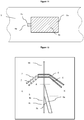
- Asymmetric focussing of the particulates in the stream is achieved by merging a particulate containing stream in a sample microfluidic channel with a guidance stream in a guidance microfluidic channel to form a common microfluidic channel containing a composite fluid stream containing a focussed beam of particulates that is disposed asymmetrically with regard to the cross-section of the common microfluidic channel.
- the asymmetric position is generally disposed towards a corner or side of the cross-section of the common channel.
- One methods of achieving this is by merging of the sample microfluidic channel and the guidance microfluidic channel at an oblique angle along only part of one or more sides of the guidance microfluidic channel, for example along only a part of one side, or only part of two adjacent sides, of the guidance channel.
- This geometry forces the particulates in the common channel into a focussed beam at a hydrodynamically favoured focal point in the cross-section of the common channel, where the focussed beam is stable and resistant to de-focussing, such that the particulates pass the detection zone in the focussed beam where the statistical spread of data measured from the particulates is reduced.
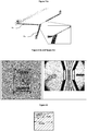
- suitable microfluidic chip architecture are provided in Figs 2 to 19 .
- the use of the microfluidic chip of the invention to sort bovine sperm cells according to sex employing impedance spectroscopy is described with reference to Figures 21 to 25 .
- the invention provides a microfluidic chip for focussing a stream of particulate containing fluid.
- the chip typically comprises a sample microfluidic channel configured to receive the stream of particulate containing fluid and a guidance microfluidic channel configured to receive a stream of guidance fluid.
- the chip comprises a common microfluidic channel formed by the merging of the sample microfluidic channel and the guidance microfluidic channel at an oblique angle.
- the merging of the sample microfluidic channel and the guidance microfluidic channel is configured to provide a composite fluid stream containing a focussed beam of particulates that is typically disposed asymmetrically in the common microfluidic channel.
- the merging of the sample microfluidic channel and the guidance microfluidic channel is configured to provide a composite fluid stream containing a focussed beam of particulates that is disposed adjacent a corner or a side of the common channel.
- the chip is configured such that the sample microfluidic channel and the guidance microfluidic channel are merged at an oblique angle along only part of one or more sides of the guidance microfluidic channel, for example along only a part of one side, or only part of two adjacent sides, of the guidance channel.
- the sample microfluidic channel has a polygonal cross-section, for example rectangular (including square), triangular.
- the polygon has 3-6 sides, preferably 3-4 sides.
- the sample microfluidic channel has a rectangular cross-section.
- the guidance microfluidic channel merges with the sample microfluidic channel along three or less sides of the polygonal or rectangular sample microfluidic channel. In none embodiment, the guidance microfluidic channel merges with the sample microfluidic channel along two sides of the polygonal rectangular sample microfluidic channel.
- the guidance microfluidic channel merges with the sample microfluidic channel along one side of the sample microfluidic channel.
- the sample microfluidic channel has a substantially square cross-section. In one embodiment, the sample microfluidic channel has a non-polygonal cross-section for example a circular or oval, or other non-polygonal cross-section. In such cases, the guidance microfluidic channel merges with the sample microfluidic channel such that the focussed beam of particulates in the common channel is disposed away from a geometric centre of the common microfluidic channel, for example disposed towards a side of the common channel.
- the guidance microfluidic channel has a polygonal cross-section.
- the guidance microfluidic channel has a rectangular cross-section.
- the guidance microfluidic channel has a substantially square cross-section. In one embodiment, the cross-sectional area of the guidance microfluidic channel is greater than the cross-sectional area of the sample microfluidic channel.
- the cross-sectional area of the guidance microfluidic channel is at least 1.5 times greater than the cross-sectional area of the sample microfluidic channel.
- the cross-sectional area of the guidance microfluidic channel is at least 2 times greater than the cross-sectional area of the sample microfluidic channel.
- the cross-sectional area of the guidance microfluidic channel is at least 3 times greater than the cross-sectional area of the sample microfluidic channel.
- the guidance microfluidic channel and the sample microfluidic channel have different aspect ratios. This is illustrated in Figures 2 , 4 , 6 , 8 , 10 , 12 , 14 , 16 , 18, 19 and 20 .
- the at least part of the sample microfluidic channel proximal to a merging zone and the common microfluidic channel are co-extensive along a common longitudinal axis, wherein the guidance microfluidic channel has a longitudinal axis that is oblique to the common longitudinal axis.
- the guidance microfluidic channel and sample microfluidic channel merge over a distance of 100 ⁇ m to 5mm, 100 ⁇ m to 4mm, 100 ⁇ m to 3mm, 500 ⁇ m to 5mm, 500 ⁇ m to 4mm, 500 ⁇ m to 3mm, or 1-5mm, 1-4mm, or 1-3mm.
- the microfluidic chip of the invention is configured for analysis of a focussed stream of particulate containing fluid, for example qualitative or quantitative analysis of the particulate containing fluid.
- the chip can analyse whether the particulates comprises a homogenous or heterogenous population, or can separate the particulates into separate populations.
- the microfluidic chip includes a detection zone comprising one or more sensors configured for sensing a characteristic of the focussed stream of particulates in the common channel.
- the sensors are configured for sensing an optical and/or electrical characteristic of the focussed stream of particulates in the common channel.
- the at least one sensor is an optical sensor.
- the at least one sensor is an electrical impedance-based sensor.
- the at least one sensor is configured to detect a characteristic of the focussed stream of particulates in the common channel, typically identify or differentiate particulates, suitably by means of impedance spectroscopy, fluorescence detection or optical scattering.
- the one or more sensors include one or at least two optical waveguides, typically including a waveguide coupled to a light source and a waveguide coupled to an optical detector configured to detect changes in an optical signal corresponding to the focussed stream of particulates passing between the waveguides.
- the one or more sensors include at least one pair of electrodes configured to detect impedance changes, whereby the at least one pair of electrodes include an excitation electrode and a detection electrode configured to detect AC impedance changes in the common channel corresponding to the focussed stream of particulates passing between the electrodes.
- the one or more sensors are disposed at least 100 ⁇ m distally from a point in which the sample and guidance microfluidic channels are fully merged. In one embodiment, the one or more sensors are disposed at least 200 ⁇ m distally from a point in which the sample and guidance microfluidic channels are fully merged. In one embodiment, the one or more sensors are disposed at least 300 ⁇ m distally from a point in which the sample and guidance microfluidic channels are fully merged. In one embodiment, the one or more sensors are disposed at least 400 ⁇ m distally from a point in which the sample and guidance microfluidic channels are fully merged. In one embodiment, the one or more sensors are disposed at least 500 ⁇ m distally from a point in which the sample and guidance microfluidic channels are fully merged.
- the one or more sensors are disposed less than 5000 ⁇ m distally from a point in which the sample and guidance microfluidic channels are fully merged. In one embodiment, the one or more sensors are disposed less than 4000 ⁇ m distally from a point in which the sample and guidance microfluidic channels are fully merged. In one embodiment, the one or more sensors are disposed less than 3000 ⁇ m distally from a point in which the sample and guidance microfluidic channels are fully merged. In one embodiment, the one or more sensors are disposed less than 2000 ⁇ m distally from a point in which the sample and guidance microfluidic channels are fully merged.
- the microfluidic chip is configured to separate the particulates into two or more sub-populations of particulates, for example 3, 4 or 5 sub-populations.
- the microfluidic chip comprises a separation zone (generally distal of the detection zone) comprising a force generator configured to exert a force on the focussed beam of particulates in the common channel to displace an individual particulate in the stream in response to changes in in the optical or electrical characteristics of the focussed stream of particulates corresponding to the individual particulate detected by the at least one sensor.
- the common microfluidic channel branches into two or more channels in the separation zone.
- the force generator is disposed to displace one or more particulates from one channel into a different channel.
- the composite fluid stream containing a focussed beam of particulates focussed stream of particulate fluid has laminar flow.
- the composite fluid stream has a Reynold Number of 1-1000.
- the composite fluid stream has a Reynold Number of 10-500.
- the composite fluid stream has a Reynold Number of 50-200.
- the particulates are cells. Other types of particulates that can be analysed using the apparatus and methods of the invention are described below.
- the apparatus is for sorting a heterogenous population of particulates into two or more homogenous populations.
- the apparatus is for sorting cells according to phenotypic differences.
- the phenotypic difference is selected from: cell type; cell sex; disease status; and cell health.
- the apparatus and methods of the invention relate to sorting of different populations of cells (for example, sorting epithelial cells from bone marrow cells).
- the apparatus and methods of the invention relate to sorting of different sub-populations of cells (for example, sorting different sub-populations of epithelial cells). In one embodiment, the apparatus and methods of the invention relate to sorting of sperm cells according to sex (for example, sorting bovine sperm cells into X and Y populations of sperm cells). In one embodiment, the apparatus and methods of the invention relate to sorting of a population of cells into living cells and dead cells. In one embodiment, the apparatus and methods of the invention relate to sorting of a cell population into cancerous cells and non-cancerous cells. In one embodiment, the apparatus and methods of the invention relate to sorting of a population of cells into healthy cells and unhealthy cells.
- the merging of the guidance and sample channels in the microfluidic chip is configured to provide a focussed beam of cells (or particulate) in the common channel in which the particulates are in single file. In one embodiment, the merging of the guidance and sample channels in the microfluidic chip is configured to provide a focussed beam of cells (or particulate) in the common channel in which the particulates are aligned in the same direction. In one embodiment, the merging of the guidance and sample channels is configured such that non-uniformly shaped particles are aligned along a plane of detection (i.e.between the electrode or optical waveguide sensors).
- the at least one sensor is configured to sense at a focal point in the cross-section of the common channel that corresponds to the position of the focussed beam of particulates.
- the hydrodynamic focussing apparatus is configured to provide anisotropic alignment of the particulates in the composite stream so that the particulates are preferentially aligned with respect to the sensor such that the difference in optical or impedance responses of different particles in amplified.
- the detection zone comprises a plurality of sensors, for example 2, 4, 6, 8, 10, 12, 14, 16 or 18 sensors.
- the plurality of sensors include at least one optical sensor and at least one electrical-based sensor (i.e. impedance sensor).
- the detection zone comprises a plurality of sensors in the same detection plane (i.e. disposed around the common channel at the same point along the channel).
- the detection zone comprises a plurality of sensors in different detection planes (i.e. disposed at different points along the channel).
- the senor comprises an excitation sensor (excitation electrode or waveguide) disposed in one detection plane and a detection sensor (detecting electrode or waveguide) disposed in a second detection plane.
- the microfluidic chip comprises two or more layers, wherein the microfluidic channel is substantially orthogonal to the layers (i.e. it extends through the two or more layers).
- the detection zone spans more than one layer. In one embodiment, the detection zone spans 2, 3, 4, 5 or 6 layers. In one embodiment, at least two of the layers comprise an electrode pair. In one embodiment, an excitation electrode of an electrode pair is disposed in one layer and a detection electrode of the same electrode pair is disposed in a second layer.
- the invention provides an apparatus comprising a microfluidic chip according to the invention.
- the apparatus comprises an electrical supply module.
- the electrical supply module is configured to energise the excitation electrode of the at least one pair of electrodes with AC voltage in the frequency range of 100 KHz to 100 MHz.
- the apparatus comprises a sample fluid supply module.
- the apparatus comprises a particulate containing fluid supply module.
- the fluid supply modules are configured to provide the fluid in laminar flow.
- the fluid supply modules are configured to provide a guidance fluid having a flow rate greater than the flow rate of the sample fluid.
- the apparatus is configured such that the AC impedance change detected by the at least one pair of electrodes comprises amplitude and phase characteristics of the AC voltage induced at the detection electrode.
- the channels of the microfluidic chip are configured to provide a composite stream of fluid in which one or both of the core stream and the guidance stream has an elongated cross section.
- the elongated stream is elongated in the plane of the at least one sensor.
- the elongated stream is elongated in a plane perpendicular to a plane of the at least one sensor.
- the channels of the microfluidic chip are configured to provide a composite steam of fluid in which a longitudinal axis of the particulate (core) stream is offset with respect to a longitudinal axis of the guidance stream.
- the cross-sectional area of the common microfluidic channel in the detection zone is in the range of 0.0001 - 0.09 mm 2 .
- Cross sectional area of 0.0001 to 0.001 are considered to be small and correspond to channels of 10-30 ⁇ min width and depth.
- Cross sectional area of 0.001 to 0.01 are considered to be medium and correspond to channels of 30-100 ⁇ min width and depth.
- Cross sectional area of 0.01 to 0.9 are considered to be large and correspond to channels of 100-300 ⁇ min width and depth.
- the cross-section of the common microfluidic channel varies along the length of the channel.
- the apparatus is configured to provide a flow rate of the sample stream of particulate fluid of 0.1 - 100 ⁇ L per minute.
- the apparatus is configured to provide a flow rate of the guidance stream of fluid of 1 - 1000 ⁇ L per minute.
- the detection zone of the microfluidic chip comprises at least two optical waveguides, at least one of these is coupled (or configured to be coupled) to a light source and the other one is coupled or configured for coupling) to an optical detector to detect optical signal resulting from the particulates and such optical signal is measured in conjunction with the electrical signal detected at the detection electrode to improve the CV of the data points from a population of particulates.
- the apparatus of the invention is configured such that the AC signal is composed of at least two different frequencies and is applied to the excitation electrodes, and the detection electrodes detect impedance change caused by single passing particulates at these very same frequencies and a particulate is attributed to X or Y sub-population on the basis of amplitude and phase signals detected at the detection electrodes at each of these frequencies.
- the particulates are cells having different phenotypes and in which the apparatus is configured to sort the cells according to phenotype.
- the particulates are cells of at least two different cell types.
- the particulates are cells of the same type having at least two different phenotypes.
- the electrodes have a thickness of 0.10-300 ⁇ m.
- the invention also provides an on-chip method of focussing a stream of particulate containing fluid that employs a microfluidic chip or apparatus of the invention.
- the method comprises the steps of:
- the method includes an additional step of on-chip analysis of the composite fluid stream in the common microfluidic channel using one or more sensors disposed in a detection zone of the common microfluidic channel, for example, optical and/or or electrical sensing methods (described herein).
- the method includes an additional step of on-chip separation of particulates in the composite fluid stream in the common microfluidic channel using a suitable particulate separator.
- the composite stream may be separated into two or more stream characterised by particulate content (i.e. having different populations of particulate).
- the on-chip separation step is coupled to the on-chip analysis step whereby separation of particulates is performed in response to the on-chip analysis.
- the particulates are sperm cells, whereby the method performs separation of the sperm cells into two populations according to sex.
- the term “comprise,” or variations thereof such as “comprises” or “comprising,” are to be read to indicate the inclusion of any recited integer (e.g. a feature, element, characteristic, property, method/process step or limitation) or group of integers (e.g. features, element, characteristics, properties, method/process steps or limitations) but not the exclusion of any other integer or group of integers.
- the term “comprising” is inclusive or open-ended and does not exclude additional, unrecited integers or method/process steps.
- the term "disease” is used to define any abnormal condition that impairs physiological function and is associated with specific symptoms.
- the term is used broadly to encompass any disorder, illness, abnormality, pathology, sickness, condition or syndrome in which physiological function is impaired irrespective of the nature of the aetiology (or indeed whether the aetiological basis for the disease is established). It therefore encompasses conditions arising from infection, trauma, injury, surgery, radiological ablation, poisoning or nutritional deficiencies.
- the term subject defines any subject, particularly a mammalian subject, for whom treatment is indicated.
- Mammalian subjects include, but are not limited to, humans, domestic animals, farm animals, zoo animals, sport animals, pet animals such as dogs, cats, guinea pigs, rabbits, rats, mice, horses, cattle, cows; primates such as apes, monkeys, orangutans, and chimpanzees; canids such as dogs and wolves; felids such as cats, lions, and tigers; equids such as horses, donkeys, and zebras; food animals such as cows, pigs, and sheep; ungulates such as deer and giraffes; and rodents such as mice, rats, hamsters and guinea pigs.
- the subject is
- “Along only part of one or more sides of the guidance microfluidic channel” as applied to the merging of the sample and guidance microfluidic channels means that the sample channel merges along only part of one or more sides, and not a full side, of the guidance channel, for example along only part of one side or only part of two adjacent sides of the guidance channel. This is illustrated in most of the figures, where the merging occurs along only part of one, or two adjacent sides, of the guidance channel.
- This geometry forces the particulates in the common channel into a focussed beam at a hydrodynamically favoured focal point in the cross-section of the common channel, where the focussed beam is stable and resistant to de-focussing, such that the particulates pass the detection zone in the focussed beam where the statistical spread of data measured from the particulates is reduced.
- “Oblique angle” as applied to the merging of the sample and guidance microfluidic channels means an angle of from 5° to 60° between longitudinal axes of the sample and guidance channels just proximal of the point of merging. In one embodiment, the oblique angle is from 05 to 45°. In one embodiment, the oblique angle is from 5° to 30°. In one embodiment, the oblique angle is from 5° to 20°.
- Porate as applied to a particulate containing fluid means a solid body in the fluid or a semi-solid, i.e. a body with properties different to that of the fluid. Examples include particles of metals, oxides, nitrides, sulphides, polymer particles, particles of inorganic or organic materials, particles of gel, also composite particles, and mixed particles, nano-particles, microparticles, particulate complexes, cells, bacteria, fungi, virus. Likewise, "particulate containing fluid” means a fluid containing particulates. Examples include cell containing fluids, such as sperm containing fluid.
- Disposed asymmetrically in the common channel as applied to the focussed beam of particulates means that the focussed beam is positioned outside the geometrical centre of the cross section common channel or outside the centre of symmetry of the common channel.
- the focussed beam generally has a longitudinal axis that is parallel to a longitudinal axis of the common channel.
- the geometrical centre means a point in the cross section of the channel that is equidistant from each corner.
- the cross-section of the common channel is not rectangular, i.e.
- the geometrical centre refers to the centroid (https://en.wikipedia.org/wiki/Centroid ), geometrical centre could alternatively be interpreted as centre of mass of the area representing the cross-section of the common channel.
- the term "disposed asymmetrically” means disposed adjacent a corner or side of the cross section of the channel.
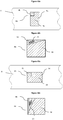
- “Hydrodynamically favoured position" as applied to the focussed beam of particulates formed in the common microfluidic channel means a position in the cross-section of the common channel in which the focussed beam is stable and unlikely to be de-focussed along the length of the common channel, alternatively, it could be defined as position/positions within the cross-section of the common channel to which the particles are guided by the balance of forces acting on the particles in the flow.
- the key forces acting on particles in the flow are listed earlier. It is an important point of this invention that usually there are several hydrodynamcially favoured positions within a channel.
- hydrodynamically favoured positions include positions close to the corners and sides of polygonal cross-sectioned channels, towards the top of the common channel (when the particulates are less dense that the fluid containing the particles), or towards the bottom of the common channel (when the particulates are more dense that the fluid containing the particles).
- the hydrodynamically favoured positions may differ from chip to chip depending on a number of variables, including the cross-sectional shape of the common channel, the flow rates of the fluid streams, and the types of particulates, the difference between the densities of the particles and the fluid.
- Alysis means determining a qualitative or quantitative characteristic of the particulates in the fluid, for example determining whether the particulates are a homogenous population or a heterogenous population, determining the amount or concentration of particulates, or differentiating or sorting the particulates based on differences.
- the term broadly covers analysis of the particulates (i.e. cells) qualitatively or quantitatively, or differentiation or sorting of the particulates based on detected impedance response differences.
- Cells means any type of cell, including mammalian cells such as sperm, white blood cells, red blood cells, bone marrow cells, immune cells, epithelial cells, nerve cells, pulmonary cells, vascular cells, hepatic cells, kidney cells, skin cells, stem cells, or bacterial and fungal cells and hybridomas.
- the particulate containing fluid contains at least two different types of particulates, for example different cell types, sperm of different sex, sub-populations of the same cell types, the same cell type having different phenotypes, dead and living cells, diseased and non-diseased cells, immature and mature cells of the same kind.
- the apparatus and methods of the invention may be employed to analyse and/or differentiate and/or separate these different types or phenotype of particulates/cells.
- “Different phenotypes” as applied to cells means different populations of cells (i.e. hepatic cells and vascular cells), different sub-populations of the same cell type (i.e. different types of cartilage cells), different phenotypes of the same cell type (i.e. cell expressing different markers, diseased and healthy cells, transgenic and wild-type cells, stem cells at different stages of differentiation).
- X and Y population as applied to sperm cells means male sperm and female sperm cells.
- “Focussed stream of particulate containing fluid” means a fluid containing particulates in the form of a focussed beam of particulates asymmetrically positioned within a guidance stream.
- the particulates in the focussed beam are focussed into a single cell stream arrangement.
- particulates in the focussed beam are aligned in the same direction.
- Microfluidic chip means a chip having at least one microfluidic channel having a cross-sectional area of less than 1 mm 2 and a length of at least 1mm. In one embodiment, the microfluidic chip has at least one microfluidic channel having a cross-sectional area of less than 0.25 mm 2 . In one embodiment, the microfluidic chip has at least one microfluidic channel having a cross-sectional area of less than 0.01 mm 2 . In one embodiment, the microfluidic chip has at least one microfluidic channel having a cross-sectional area of less than 0.0025 mm 2 .
- the microfluidic chip has a plurality of microfluidic channels, for example at least 2, 3, 4, 5, 6, 7, 8, 9 or 10 microfluidic channels. In one embodiment, the microfluidic chip has at least one microfluidic channel having a length of at least 1.500 mm. In one embodiment, the microfluidic chip has at least one microfluidic channel has a length of at least 2 mm. In one embodiment, the microfluidic chip has a length of at least 3 mm. In one embodiment, the microfluidic chip comprises a plurality of layers, for example at least 2, 3, 4, 5, 6, 7, 8, 9 or 10 layers.
- Substantially orthogonal microfluidic channel means that the microfluidic channel runs through the chip as opposed to parallel to the layers of the chip.
- the channel may be perpendicular to the layers of the chip, or run through the layers of the chip at an angle, for example at an angle of 60° or 70° to a longitudinal axis of the layers of the chip.
- AC impedance changes should be understood to mean changes in impedance detected at the detection electrode.
- the changes may include changes in amplitude, phase, or amplitude and phase of the signal.
- Electrodes In electrical communication with the microfluidic channel as applied to the electrodes means that the electrodes are in direct contact with the fluids analysed in the microfluidic channel.
- Detection plane means a cross-section of the microfluidic channel at which an electrode pair is located.
- the apparatus of the invention allows for a plurality of electrode pairs to be disposed at the same detection plane (as shown in Figure 7 ), where the electrode pairs are spaced apart radially around the channel in the same plane. It also allows for a plurality of electrode pairs to be provided at different detection planes (see for example Figure 8 ), where the electrode pairs are spaced apart axially along the channel.
- Separatation zone is a part of the microfluidic chip, distal of the detection zone, where particulates in the fluid can be separated based on the AC impedance changes in the channel caused by the particulates and in accordance with the results of the characterization of the particulates in the detection zone.
- the separation zone generally includes a force generator operably connected to the electrode pair and configured to exert a force on the particulates in response to signals from the detection zone, to separate the one or more particulates from the stream of fluid. Examples of suitable force generators for use in cell sorting apparatus are well known in the art and described for example in [ 15 ].
- the apparatus will typically include a processor operably connected to the at least one electrode pair and the force generator, and configured to actuate the force generator in response to a signal received from the electrode pair.
- the actuating signal may be pre-programmed into the processor, and may vary from cell type to cell type.
- anisotropic refers to being not spherical in overall symmetry of particle's shape or its response to the stimulus used in the apparatus. In the simplest case, this refers to overall shape of the particle (cell). For example, if the particle is elongated, ellipsoidal, bar-shaped or disk-shaped, discoid, this is then described as anisotropic in contrast to a spherical shape particle that is being described as isotropic. However, the overall shape in its own right is insufficient to distinguish between anisotropic and isotropic particles (cells).
- a conducting rod segment of wire
- this forms an anisotropic particle even if the overall shape of the particle is spherical, i.e. isotropic.
- the reason is that such a particle has different response to the Radio Frequency (RF) electromagnetic field depending on whether it is directed with the length of the rod along the field or perpendicular to the field.
- RF Radio Frequency
- the main contribution to RF signal response from a cell may not come from the exterior periphery of the cell but from its interior features. This depends on the structure of the cell and the RF frequency.
- the effect of particle focusing may still be achieved when Reynolds number is below 1 and therefore the invention is not restricted to the situation of ⁇ 1 ⁇ Re ⁇ 1000.
- the range of Re values at which the focusing is achieved also depends of the difference between the densities of the liquid and the density of the particles. The greater is the difference, e.g.
- the heavier are the particles compared to the liquid, the greater is the effective gravity force (difference between the gravity force and the buoyance force) pulling the particles down from the locations defined by the hydrodynamic forces. Therefore, the greater is the difference between the densities, the greater should be the force bringing the particles towards hydrodynamically favored positions to achieve effective focusing of the particle's trajectories.
- This invention relates to the field of microfluidic flow cytometry and more generally microfluidic techniques for analysis of particulate-containing fluids. It deals with the improvements to such techniques in order to identify subsets of particles or sub-populations of cells that differ by their properties, and separate the said identified sub-populations of cells or subsets of particles, if so required.
- the invention deals with a microfluidic chip, whereby the stream of particles or cells is positioned within a cross-section of the microfluidic channel in a controlled way to reduce a variation of detected signal and thus make distinction between subsets of cells or particles, more robust.
- the invention teaches that locations exist within the channel of a detection zone of microfluidic chip at which the statistical spread of the data measured from a set of cells or particles, is reduced under suitable hydrodynamic conditions. This reduction is achieved by a more tightly focused flow of particles (cells) within the channel and also by a more homogeneous alignment of the particles (cells) within the channel. The latter is particularly useful if the particles (cells) are not circular in shape, e.g. elongated, elliptical or discoid.
- the invention also teaches how to guide the cells or particles through such preferable locations and the hydrodynamic conditions at which the focusing of particles could be achieved.
- the invention provides a microfluidic chip for positioning of particles of a particulate-containing fluid
- a microfluidic chip for positioning of particles of a particulate-containing fluid
- the hydrodynamically favoured position is located substantially outside the geometrical centre of the common channel.
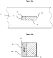
- the hydrodynamically favoured position is in the vicinity of one or several corners of the common channel and the common channel is of a rectangular shape.
- the hydrodynamically favoured position is located in the vicinity of the middle points of some of the sides of the common channel and the common channel is substantially of a rectangular or a square cross-section.
- the common channel is of a rectangular cross-section with the width being substantially greater than the height and the hydrodynamically favoured position is located close to one of the centres of the longer sides of the rectangle forming the interior of the common channel cross-section.
- the particulate-containing fluid and guidance fluid are merged in a substantially non-symmetric fashion so that particulate containing fluid is injected into the flow of guidance fluid in a substantially asymmetric fashion.
- the particulate containing fluid is injected close to such a point in the cross-section of the common channel that projects on to the hydrodynamically favoured position within the common channel by following the lines of fluid flow in the common channel from the point of injection of the particulate containing fluid to the detection zone within the common channel.
- the particulate-containing fluid flow is merged with the guidance fluid by injecting the particulate-containing fluid at the peripheral point of the cross-section of the channel carrying the guidance fluid.
- the hydrodynamically favoured position is selected from several such possible hydrodynamically stable positions within the cross-section of the channel so that the hydrodynamically favoured position is located in the lower part of the channel for the analysis of particulate containing fluid provided that the particles (cells) have greater density than the density of the particulate containing fluid, and is located in the upper part of the channel provided that the particles (cells) have smaller density than the density of the particulate containing fluid; and the guidance fluid flow is arranged in such a way that the particles (cells) are guided towards the selected hydrodynamically favoured position.
- the channel of the guidance fluid has a rectangular cross-section.
- the particulate fluid flow is injected close to one of the corners of the channel of the guidance fluid.
- the particulate fluid flow is injected close to the centre of one of the sides of the channel carrying the guidance fluid.
- the particulate fluid is injected away from the centre of the channel carrying guidance fluid.
- the chip is used for identification of the particles (cells) using impedance spectroscopy and the particles guided by the guidance fluid, pass through a detection zone with electrodes; of these electrodes at least one is the excitation electrode and at least one is the detection electrode.
- the excitation electrode (electrodes) are excited at at least two different frequencies in the range of 0.1 to 200 MHz and the signals are measured at the detection electrodes at these very frequencies.
- the signal measured at the detection electrode is a complex signal comprising both, the amplitude and the phase characteristics of the detection signal.
- the guidance fluid directs particles (cells) in a uniform fashion with respect to the electrodes of the detection zone.
- the guidance fluid directs the particles (cells) to such a trajectory within the detection zone of the common channel that particles (cells) pass parallel to the electrodes and the separation distance from the particles to the electrodes at these trajectories is kept nearly the same for all the particles as their trajectories are on the line of hydrodynamically favoured positions for the particles in the common channel.
- the particles are anisotropic in shape, and the hydrodynamically favoured position is chosen in the vicinity of at least one wall of the channel so that the effect of the wall and hydrodynamic flow forces rotate particles to align them in the same orientation with respect to the electrodes.
- the separation of particles follows their identification in the detection zone and such separation takes place in the separation zone at which cell arrive after exiting the detection zone.
- the hydrodynamically favoured position is located close to one of the four four of the common channel. In one embodiment, the hydrodynamically favoured position is located close to one of the four corners of the common channel.
- the hydrodynamically favoured position is located close to one of the four sides of the common channel and the common channel is of substantially rectangular or square cross-section.
- the hydrodynamically favoured position is defined by the geometry of the channel, flow rate and characteristics of the particles including their density, size and characteristics of the particulate-containing fluid and the guidance fluids including their densities and viscosities.
- the invention also provides a microfluidic chip for identification of particles of a particulate-containing fluid using impedance spectroscopy, such chip transporting the particles through a common channel towards the detection zone having electrodes; of these electrodes at least one is the excitation electrode and at least one is the detection electrode; where such a chip further comprises means for merging the flows of the particulate-containing fluid and a guidance fluid in a single common channel in such a way that the trajectory of particulate-containing fluid in the detection zone of the common channel is guided by the guidance fluid to pass through a hydrodynamically favoured position for the particles within the common channel, where the trajectories of individual particles are bundled into a focused beam of near straight lines by the forces acting on particles in the laminar flow in the common channel and the flow of guidance fluid guides the particles towards some subset of the hydrodynamically favoured positions in the common channel, away from other such hydrodynamically favoured positions; and such positions to which the particles are guided, are located closer to the excitation electrodes than other hydrodynamic
- the excitation electrode (electrodes) are excited at two or more different frequencies in the range of 0.1-200 MHz and the signals are measured at the detection electrodes at these very frequencies.
- the signal measured at the detection electrode is a complex signal comprising both, the amplitude and the phase characteristics of the detection signal.
- the particles are anisotropic in shape, and the hydrodynamically favoured position is chosen in the vicinity of at least one wall of the channel so that the effect of the wall and hydrodynamic flow rotates particles to align them preferentially in the same orientation with respect to the electrodes.
- the invention also provides a microfluidic chip for positioning of particles of a particulate containing fluid comprising means for merging the flows of the particulate-containing fluid and a guidance fluid in a single common channel in such a way that the trajectory of particulate-containing fluid in the detection zone of the common channel is guided by the guidance fluid to pass through a hydrodynamically favoured position for the particles within the common channel, where the trajectories of individual particles are bundled into a focused beam of near straight lines by the forces acting on particles in the laminar flow in the common channel; and optical detection is used for the identification of the particles.
- the hydrodynamically favoured position is located substantially outside the geometrical centre of the common channel.
- the hydrodynamically favoured position is in the vicinity of one or several of the corners of the common channel and the common channel is of a rectangular shape.
- the hydrodynamically favoured position is located in the vicinity of the middle points of some of the sides of the common channel and the common channel is of a rectangular or a square cross-section.
- the common channel is of a rectangular cross-section with the width being substantially greater than the height and the hydrodynamically favoured position is located close to one of the centres of the longer sides of the rectangle forming the interior of the common channel cross-section.
- the particulate-containing fluid and guidance fluid are merged in a substantially non-symmetric fashion so that particulate containing fluid is injected into the flow of guidance fluid in a substantially asymmetric fashion.
- the particulate-containing fluid flow is merged with the guidance fluid by injecting it at the peripheral point of the cross-section of the channel carrying the guidance fluid.
- the particulate containing fluid is injected close to such a point in the cross-section of the common channel that projects on to the hydrodynamically favoured position within the common channel by following the lines of fluid in the common channel from the point of injection of the particulate containing fluid to the detection zone within the common channel.
- the particles are anisotropic in shape, and the hydrodynamically favoured position is chosen in the vicinity of at least one wall of the channel so that the effect of the wall and hydrodynamic flow forces rotate particles to align them in the same orientation with respect to the incoming optical beam of the detector.
- the invention also provides a microfluidic chip for positioning and alignment of particles of a particulate-containing fluid; such particles being anisotropic in shape; comprising means for merging the flows of the particulate-containing fluid and a guidance fluid in a single common channel to form a focused beam of lines of the particles trajectories by the forces acting on particles in the laminar flow in the common channel where the direction of the alignment of particles' short axes in the case of discoid particles or long axis in the case of elongated particles; is along the boundary separating the body of particulate-containing fluid from the body of guidance fluid in the common channel
- the particulate-containing fluid and guidance fluid are merged in a substantially non-symmetric fashion so that particulate containing fluid is injected into the flow of guidance fluid in a substantially asymmetric fashion.
- the particulate-containing fluid flow is merged with the guidance fluid by injecting the particulate-containing fluid at the peripheral point of the cross-section of the channel carrying the guidance fluid.
- This invention tackles the problem of variability of signal in a microfluidic flow cytometer or particle analyzer. It teaches the way of hydrodynamically focusing particles and cells within the detection channels to reduce the signal variability, provides the apparatus and method to practice the invention. Contrary to the conventional three-dimensional hydrodynamic focusing used with microfludic chips where the flow of particles is focused at the center of the channel, the invention suggests that particles/cells should not be focuses into the center of the detection channel. In contrast to the prior art we use sheath stream in order to focus particles into the corners of the flow channel, where their position is stable under the correctly suitable conditions of laminar flow. Our apparatus and method take into account stable hydrodynamic positions of particles due to the inertial lift forces and therefore provide more stable focusing than used in prior art technologies.
- the invention also provides a microfluidic chip for identification of particles of a particulate-containing fluid using impedance spectroscopy, such chip transporting the particles through a common channel towards the detection zone having electrodes; of these electrodes at least one is the excitation electrode and at least one is the detection electrode; where such a chip further comprises means for merging the flows of the particulate-containing fluid and a guidance fluid in a single common channel in such a way that the trajectory of particulate-containing fluid in the detection zone of the common channel is guided by the guidance fluid to pass through a hydrodynamically favoured position for the particles within the common channel, where the trajectories of individual particles are bundled into a focused beam of near straight lines by the forces acting on particles in the laminar flow in the common channel, and wherein the flow of guidance fluid guides the particles towards some subset of the hydrodynamically favoured positions in the common channel, away from other such hydrodynamically favoured positions; and wherein such positions to which the particles are guided, are located closer to the excitation electrode
- the excitation electrode (electrodes) are excited at two or more different frequencies in the range of 0.1 to 200 MHz and the signals are measured at the detection electrodes at these very frequencies.
- the signal measured at the detection electrode is a complex signal comprising both, the amplitude and the phase characteristics of the detection signal.
- the particles are anisotropic in shape, and the hydrodynamically favored position is chosen in the vicinity of at least one wall of the channel so that the effect of the wall and hydrodynamic flow rotates particles to align them preferentially in the same orientation with respect to the electrodes.
- Microfluidic chip for positioning and alignment of particles of a particulate-containing fluid in which the particles are anisotropic in shape, the chip comprising means for merging the flows of the particulate-containing fluid and a guidance fluid in a single common channel to form a focused beam of lines of the particles trajectories by the forces acting on particles in the laminar flow in the common channel, where the direction of the alignment of particles' short axes in the case of discoid particles or long axis in the case of elongated particles is along the boundary separating the body of particulate-containing fluid from the body of guidance fluid in the common channel
- Figures 2a, 2b , and 2c show cross-section of the two channels: the smaller channel 4a carries the particulate containing fluid 4b and the larger channel 5a is carries the guidance fluid 5b.
- the guidance fluid is not shown for clarity of the drawings.
- the entire cross-section 5a of the channel is normally filled with the guidance fluid.
- the particulate containing fluid channel 4a has the cross section with the width and height in the range of 0.005 -1 mm. In some special cases the width out to 10 mm could be considered if it is combined with the small height in the sub-millimeter range.
- the guidance fluid carrying channel 5a has the cross-section in the range of 0.05-10 mm x 0.05-10 mm.
- the channels 4a and 5a are made out of polymer materials such as PMMA but could also be made out non-polymer materials, e.g. glass.
- Figure 2a shows the two channels 4a and 5a at the point where they merge, at the cross section A-A' of Figure 3 .
- the wall separating the two channels indicated by numeral 3 disappears at that point and the wall position is shown with dashed line.
- Figure 2c shows the two channels 4a and 5a at the cross-section C-C' of Figure 3 where the wall 3 separating the two channels has the finite width, typically in the range of 0.005 - 1 mm.
- Figure 2b shows the two channels 4a and 5a at the cross-section B-B' of Figure 3 .
- FIG. 3 The top view of the fragment of the apparatus is shown in Figure 3 .
- the two channels 4a and 5a merge to form a single common channel 8a.
- Figures 2d , 2e, 2f show details of the common channel 8a at the cross-sections D-D', E-E' and F-F' respectively.
- the common channel 8a may have the dimensions different to the ones of the particulate fluid carrying channel 4a.
- the positions of the particles 4b (cells) are indicated on each channel by a cloud of dots.
- the common channel 8a typically has a smaller cross-section than the cumulative cross-section of the particulate containing fluid channel 4a and the guidance fluid channel 5a.
- the common channel 8a typically has interior width and height in the range of 0.005-10 mm. All the three channels could be fabricated on a single microfluidic chip indicated by numeral 8.
- the embodiment shown in Figure 2f and in Figure 3 also shows the electrodes of the impedance spectroscopy apparatus (excitation electrode 6 and measurement electrode 7). In this case the detection and identification of particles is based on measurements of changes to impedance due to particles passing in between the electrodes 6 and 7.
- the embodiment has four electrodes, two of these are located above the common channel 8a (indicated by 6 and 6') and two electrodes are below it (indicated by 7 and 7').
- the channel upper and lower walls are in the range of 0.1-10 mm but typically could be around 0.5 mm.
- the distance from the point where the two channels merge to the location of the electrodes is typically in the range of 0.05-1 mm but could also be outside this range.
- the location where the electrodes 6, 6', 7 and 7' are positioned is called the detection zone.
- the hydrodynamically favored positions are at the four corners of the common channel 8a. They are marked by numerals 9a, 9b, 9c, 9d. These four hydrodynamic favored positions 9a-9d are achieved e.g. for the suspension of red blood cells in phosphate saline buffer, with the flow velocity of 0.56 m/sec and the size of the channel of 30 micrometers width by 30 micrometers height.
- the flow velocity we refer to the velocity at the center of the common channel 8a.
- This velocity in a laminar flow channel is greatest at the center of the channel and it declines closer to the walls of the channel.
- the linear velocity of the fluid in the common channel 8a is much greater than the velocity in the guidance fluid channel 5a.
- the injection of the particulate containing fluid 4b into the upper left corner of the guidance fluid channel 5a favors position 9a over the other three positions.
- the favored positions of the cells are located some distance away from the walls of the common channel. The location of the favored position depends on the Reynolds number defined by the density and viscosity of the fluid, linear velocity of the flow, dimensions of the channel.
- the favored position is located some 0.005 mm from each of the two walls forming the corner. These values scale up or down with the overall width and height of the common channel and the flow conditions.
- the four hydrodynamically favored positions in a common channel of a rectangular cross-section are not always equally suitable for particle analyser (cell cytometer). If the density of the particles (cells) is significantly greater than the density of the particulate containing fluid, it may be preferable to select the position at one of the lower corners of the common channel.
- the selected hydrodynamically favored position is located closer to the floor of the common channel, it may be advantageous to swap the positions of the excitation 6 and 6' and detection electrodes 7 and 7' to increase the sensitivity of the cytometer so that the excitation electrodes 7 and 7' are located closer to the particles (cells) in the channel.
- the relative positions of the particulate containing channel with respect to the guidance fluid channel cross-section is given by the selected hydrodynamically favored position. In this case the selected hydrodynamically favored position is at the upper left corner of the common channel and this determines that injection of the particulate containing fluid is done at the upper left corner of the guidance fluid channel.
- the cells come though the favored location forming tight bundle of trajectories as shown in Figure 2f .
- the dimension of the cross-section of the bundle in the detection zone depend of the flow conditions such as flow velocity (flow rate), the distance from the point where the channels merge, to the detection zone and the dimensions of the common channel.
- flow rate flow velocity
- the particles (cells) could be bundled into a much tighter bundle in any of the hydrodynamically favored positions.
- Figure 4 corresponds to cross-section K-K' of Figure 5 .
- the embodiment has height of the common channel 8a the same as the height of the particulate containing fluid 4a channel, which makes it easier to fabricate the chip using polymer photolithography method using SU-8 photopolymer material.
- the width of the common channel 8a may or may not be equal to that of the particulate containing fluid channel 4a.
- Embodiment in Figure 5 shows the situation when the two widths are equal. In this way the common channel 8a is a geometrical continuation of the particulate containing fluid channel 4a along its axis.
- the common channel 8a makes an angle with the direction of the particulate containing fluid 4a channel, i.e. there is a bend along the length of the common channel 8a.
- the guidance fluid channel 5a is directed to form the angle of 3-30 degrees with the particulate containing fluid channel 4a.
- the embodiment shown in Fig. 5 differs from the embodiment in Fig. 3 where the guidance fluid channel 5a is tangent to the particulate fluid channel 4a at the point of them merging, i.e. the angle between them is zero.
- the guidance fluid channel 5a vanishes at the point marked by a letter A on Figure 5 .
- the widths and heights of the guidance fluid channel 5a, particulate containing fluid channel 4a and the common channel 8a, wall thickness of the channel floor and channel ceiling, are similar to the dimensions of these indicated in reference to Figures 2 and 3 as well as the linear flow velocities in the channels.
- the particulate containing fluid channel 4a is located just above the guidance fluid channel 5a and, unlike in the embodiment shown in Figure 2 , there is no wall separating them which makes it easier to fabricate compared to the microfluidic chip shown in Figure 2 .
- the particulate fluid containing channel 4a and the guidance fluid channel 5a merge between the points B and A marked in Figure 5 . In this case the particulate containing fluid 4b is guided towards one of the four hydrodynamically favored positions located proximal to the upper left corner of the common channel 8a.
- Figures 6 and 7 show another embodiment where the particulate containing fluid channel 4a enters into the guidance fluid channel 5a at its top right corner.
- Figure 6 shows cross-section of the channel shown in Figure 7 along the line K-K'.
- the two channels 4a and 5a are shown in Figure 7 as separated by a solid line, however, there is no wall separating the two channels at that point. All the points related to the dimensions of the channels, the flow conditions, electrodes, manufacturability of the microfluidic chip, etc. made in relation to Figures 4 and 5 , apply also to Figures 6 and 7 .
- the particulate containing fluid 4b is guided towards one of the four hydrodynamically favored positions located proximal to the upper left corner of the common channel.
- the particulate fluid carrying channel 4a and the guidance channel 5a do not have to have rectangular or square cross-sections.
- Embodiment where the particulate fluid carrying channel 4a has a triangular cross-section is shown in Figure 8 and Figure 9 . All the description and meaning of the elements of the drawings related to Figures 4 and 5 , also apply to Figures 8 and 9 .
- the electrodes of the impedance spectrometer are not shown for brevity. It should be stressed that any of the embodiments shown in this disclosure document can be used without any electrodes as impedance spectroscopy is only one of several possible methods that could be used for the analysis of particles (cells).
- Figures 10 and 11 Another embodiment is shown in Figures 10 and 11 .
- the description and meaning of the elements of the drawings related to Figures 4 and 5 also apply to Figures 10 and 11 and will not be repeated for brevity.
- the particulate containing fluid is guided towards one of the four hydrodynamically favored positions located proximal to the upper left corner of the common channel.
- Figures 12 and 13 Another embodiment is shown in Figures 12 and 13 .
- particulate fluid containing channel 4a is located above the guidance fluid channel 5a, the same it is in Figures 4 and 5 .
- the two channels are separated by a wall (membrane) 3 in some section of the channel. This section is shown by a dashed triangle in Figure 13.
- Figure 12 corresponds to the cross-section along the line K-K' of Figure 13 .
- the membrane 3 vanishes and the guidance fluid channel 5a is tapered off to zero width.
- the guidance fluid channel 5a is tapered off in along the common channel 8a in the range been the points B and A marked on Figure 13 .
- the particulate containing fluid 4b is guided towards one of the two hydrodynamically favored positions located proximal to the centers of the two opposite sides of the common channel: the upper wall of the common channel, it's ceiling.
- Figures 14 and 15 show another embodiment of the apparatus. The notations are the same as in previous figures.
- the guidance fluid channel 5a is tapered off between the points B and A along the common channel.
- Figure 14 represents cross-section along the line K-K' of Figure 15 .
- FIGS 16 and 17 show another embodiment of the apparatus. The notations are the same as in previous figures.
- Fig 18a and 19a show the cross-sections of the particulate containing fluid channel 4a and the guidance fluid channel 5a at the point where they merge.
- the cross-section areas of each of these channels are the same in Figure 18a and in Figure 19a .
- the guidance fluid channel 5a is has greater height than the width.
- Figures 18b and 19b show cross sections of the common channel 8a with the scale five times that of Figures 18a and 19a (i.e. common channel is shown enlarged).
- the particles or cells 20 are aligned much closer to the vertical line compared to the embodiment of Figure 18b . This is shown schematically by a shadowed ellipse.
- FIG. 20b shows the cross-section of the common channel 8a short distance away from the cross-section shown in Figure 20a , some 0.1 mm downstream and the cross-section in Figure 20b is shown with the scale five times greater than that in Figure 20a (enlarged).
- the line separating the particulate containing fluid 4b from the guidance fluid 5b is vertical and the cells or particles 20 will be aligned with the longer axis directed vertically.
- Semen cell are typical example of non-circular cells accurate impedance detection of which are difficult and depends on the orientation and alignment of cells in respect to the surface of the detection electrodes.
- impedance chips with channel configuration displayed in Figure 21a where semen cells flowing in the sample flow channel 4a coming from the top and left are subjected to the guidance fluid in the guidance fluid channel 5a which is coming from the bottom and from the right.
- the chip produced is shown in the Figure 21b .
- the close-up of the channel intersection and the detection area is displayed in the Figures 21c .
- Conditions 3 and 4 were with focusing ratios to match semen size to the dimension of the sample stream according to Figure 22 .
- the impedance detection has been conducted by triggering on change of the impedance signal at excitation frequency of 0.5 MHz and detecting the change of impedance amplitude and impedance phase at excitation frequency of 15MHz to differentiate between different subpopulations of cells.
- the impedance diagrams (X axis-impedance amplitude at 15MHz and Y axis impedance phase at 15MHz) are presented in Figures 23a - 23e .
- Figure 23a we have displayed the result of experiment with no hydrodynamic focusing of cells, where sample flow rate was 30 ul/min and guidance flow was stopped.
Landscapes
- Chemical & Material Sciences (AREA)
- Health & Medical Sciences (AREA)
- General Health & Medical Sciences (AREA)
- Life Sciences & Earth Sciences (AREA)
- Dispersion Chemistry (AREA)
- Analytical Chemistry (AREA)
- Biochemistry (AREA)
- Physics & Mathematics (AREA)
- Engineering & Computer Science (AREA)
- General Physics & Mathematics (AREA)
- Immunology (AREA)
- Pathology (AREA)
- Hematology (AREA)
- Clinical Laboratory Science (AREA)
- Chemical Kinetics & Catalysis (AREA)
- Biotechnology (AREA)
- Wood Science & Technology (AREA)
- Organic Chemistry (AREA)
- Zoology (AREA)
- Bioinformatics & Cheminformatics (AREA)
- Genetics & Genomics (AREA)
- Cell Biology (AREA)
- Sustainable Development (AREA)
- Biomedical Technology (AREA)
- Fluid Mechanics (AREA)
- General Engineering & Computer Science (AREA)
- Molecular Biology (AREA)
- Microbiology (AREA)
- Investigating Or Analyzing Materials By The Use Of Electric Means (AREA)
- Apparatus Associated With Microorganisms And Enzymes (AREA)
- Investigating, Analyzing Materials By Fluorescence Or Luminescence (AREA)
- Automatic Analysis And Handling Materials Therefor (AREA)
- Optical Measuring Cells (AREA)
- Investigating Or Analysing Materials By Optical Means (AREA)
- Measuring Or Testing Involving Enzymes Or Micro-Organisms (AREA)
- Micromachines (AREA)
Claims (15)
- Puce microfluidique pour la focalisation d'un flux de fluide contenant des particules et l'analyse du flux focalisé, comprenant :un canal microfluidique configuré pour recevoir le flux de fluide contenant des particules ; etune zone de détection comprenant un ou plusieurs capteurs électriques incluant au moins une paire d'électrodes incluant une électrode d'excitation (6, 6') et une électrode de détection (7, 7') configurées pour détecter les changements d'impédance en courant alternatif dans le canal microfluidique correspondant au flux de particules passant entre les électrodes,caractérisée en ce que la puce microfluidique comprend :un canal microfluidique d'échantillon (4a) configuré pour recevoir le flux de fluide contenant des particules (4b) ;un canal microfluidique de guidage (5a) configuré pour recevoir un flux de fluide de guidage (5b) et ayant une section transversale polygonale ; etun canal microfluidique commun (8a) formé par la fusion du canal microfluidique d'échantillon et du canal microfluidique de guidage à un angle oblique de 5° à 60° le long d'une partie d'un côté du canal microfluidique de guidage, où la fusion du canal microfluidique d'échantillon et du canal microfluidique de guidage est configurée pour fournir un flux de fluide composite contenant un flux focalisé de particules qui est disposé de manière asymétrique (9) dans le canal microfluidique commun adjacent à un coin ou un côté du canal commun,
où l'au moins une paire d'électrodes est configurée pour détecter les changements d'impédance en courant alternatif dans le canal microfluidique commun correspondant au flux focalisé de particules passant entre les électrodes. - Puce microfluidique selon la revendication 1, dans laquelle le canal microfluidique d'échantillon (4a) fusionne avec le canal de guidage le long d'une partie de deux côtés du canal microfluidique de guidage (5a).
- Puce microfluidique selon la revendication 1 ou 2, dans laquelle une zone de section transversale du canal microfluidique de guidage (5a) est au moins 1,5 fois plus grande qu'une zone de section transversale du canal microfluidique d'échantillon (4a).
- Puce microfluidique selon l'une quelconque des revendications précédentes, dans laquelle le canal microfluidique d'échantillon (4a) a une section transversale polygonale.
- Puce microfluidique selon la revendication 4, dans laquelle le canal microfluidique de guidage (5a) fusionne avec le canal microfluidique d'échantillon (4a) le long de 1 ou 2 côtés du canal microfluidique d'échantillon et dans laquelle le canal microfluidique d'échantillon est rectangulaire.
- Puce microfluidique selon la revendication 1, configurée de telle sorte que le changement d'impédance en courant alternatif détecté par l'au moins une paire d'électrodes (6, 7) comprend des caractéristiques d'amplitude et de phase de la tension alternative induite au niveau de l'électrode de détection.
- Puce microfluidique selon l'une quelconque des revendications précédentes, dans laquelle la fusion des canaux de guidage (5a) et d'échantillon (4a) dans la puce microfluidique est configurée pour fournir un flux focalisé de particules (9) dans le canal commun dans lequel les particules sont alignées dans la même direction.
- Puce microfluidique selon l'une quelconque des revendications précédentes, configurée pour fournir un alignement anisotrope des particules dans le flux composite de sorte que les particules sont préférentiellement alignées par rapport au capteur de telle sorte que la différence de réponses d'impédance de différentes particules est amplifiée.
- Puce microfluidique selon l'une quelconque des revendications précédentes, dans laquelle la fusion des canaux de guidage et d'échantillon dans la puce microfluidique est configurée de telle sorte que la trajectoire du fluide contenant des particules dans la zone de détection du canal commun est guidée par le fluide de guidage pour passer par une position hydrodynamiquement favorisée pour les particules au sein du canal commun, où les trajectoires des particules individuelles sont regroupées en un flux focalisé de lignes presque droites par les forces agissant sur les particules dans l'écoulement laminaire dans le canal commun et l'écoulement de fluide de guidage guide les particules vers un certain sous-ensemble des positions hydrodynamiquement favorisées dans le canal commun, en les éloignant d'autres positions hydrodynamiquement favorisées ; et ces positions vers lesquelles les particules sont guidées sont situées plus près des électrodes d'excitation que d'autres positions hydrodynamiquement favorisées au sein du canal commun.
- Puce microfluidique selon l'une quelconque des revendications précédentes, comprenant une zone de séparation distale de la zone de détection comprenant un générateur de force configuré pour exercer une force sur le flux focalisé de particules dans le canal commun pour déplacer une particule individuelle dans le flux en réponse à des changements dans les caractéristiques électriques du flux focalisé de particules correspondant à la particule individuelle détectée par l'au moins un capteur électrique.
- Procédé sur puce de focalisation d'un flux de fluide contenant des particules et d'analyse du flux focalisé qui emploie une puce microfluidique selon l'une quelconque des revendications 1 à 10, le procédé comprenant les étapes consistant à :pomper un fluide contenant des particules à travers le canal microfluidique d'échantillon ;pomper simultanément un fluide de guidage dans le canal microfluidique de guidage, ce par quoi les fluides fusionnent pour former un flux de fluide composite contenant un flux focalisé de particules qui est disposé de manière asymétrique dans le canal microfluidique commun ; etanalyser sur puce le flux de fluide composite dans le canal microfluidique commun à l'aide de l'au moins une paire d'électrodes disposées dans une zone de détection du canal microfluidique commun configurée pour détecter les changements d'impédance en courant alternatif dans le canal commun correspondant du flux focalisé de particules passant entre les électrodes.
- Procédé sur puce selon la revendication 11, dans lequel le procédé inclut une étape supplémentaire de séparation sur puce de particules dans le flux de fluide composite dans le canal microfluidique commun à l'aide d'un séparateur de particules approprié, dans lequel l'étape de séparation sur puce est couplée à l'étape d'analyse sur puce, ce par quoi la séparation de particules est effectuée en réponse à l'analyse sur puce.
- Procédé sur puce selon la revendication 11 ou 12, dans lequel les particules ont une forme anisotrope, et les particules dans le flux focalisé sont alignées dans la même direction.
- Procédé sur puce selon la revendication 13, dans lequel les particules sont des spermatozoïdes, et dans lequel le procédé est un procédé d'analyse et de séparation de spermatozoïdes selon le sexe.
- Procédé sur puce selon la revendication 13, dans lequel le fluide de guidage a un débit supérieur au débit du fluide d'échantillon.
Applications Claiming Priority (2)
| Application Number | Priority Date | Filing Date | Title |
|---|---|---|---|
| EP16166177 | 2016-04-20 | ||
| PCT/EP2017/059453 WO2017182599A1 (fr) | 2016-04-20 | 2017-04-20 | Puce microfluidique pour focaliser un flux de fluide contenant des particules |
Publications (2)
| Publication Number | Publication Date |
|---|---|
| EP3445492A1 EP3445492A1 (fr) | 2019-02-27 |
| EP3445492B1 true EP3445492B1 (fr) | 2021-09-15 |
Family
ID=55794906
Family Applications (1)
| Application Number | Title | Priority Date | Filing Date |
|---|---|---|---|
| EP17723635.3A Active EP3445492B1 (fr) | 2016-04-20 | 2017-04-20 | Puce microfluidique pour focaliser un courant de fluide contenant des particules |
Country Status (10)
| Country | Link |
|---|---|
| US (1) | US11633737B2 (fr) |
| EP (1) | EP3445492B1 (fr) |
| JP (1) | JP2019518971A (fr) |
| CN (1) | CN109689212A (fr) |
| AU (1) | AU2017251990A1 (fr) |
| BR (1) | BR112018071562A2 (fr) |
| CA (1) | CA3021609A1 (fr) |
| MX (1) | MX2018012862A (fr) |
| RU (1) | RU2018136932A (fr) |
| WO (1) | WO2017182599A1 (fr) |
Families Citing this family (7)
| Publication number | Priority date | Publication date | Assignee | Title |
|---|---|---|---|---|
| EP3556845A1 (fr) | 2018-04-20 | 2019-10-23 | Cellix Limited | Procédé et dispositif de transfection de cellules |
| US20220162540A1 (en) | 2019-03-29 | 2022-05-26 | Cellix Limited | Method and device for transfecting cells |
| CN111135882B (zh) * | 2019-12-30 | 2021-07-09 | 南方科技大学 | 一种二维流动聚焦装置 |
| EP3871773A1 (fr) | 2020-02-27 | 2021-09-01 | Cellix Limited | Procédé de détermination de l'état de transfection d'une pluralité de cellules |
| WO2022109225A1 (fr) * | 2020-11-20 | 2022-05-27 | The Trustees Of Princeton University | Système et procédé pour la microfluidique à entraînement électronique sans pneumatique pour permettre une variabilité d'échelle massive avec détection intégrée cellulaire et biomoléculaire |
| CN112698024B (zh) * | 2020-12-08 | 2022-04-26 | 华中农业大学 | 一种基于差分阻抗颗粒计数的免疫分析方法 |
| CN114112826B (zh) * | 2021-11-25 | 2024-04-19 | 天津大学 | 用于荧光微粒的声光互联微流控检测系统和检测方法 |
Family Cites Families (10)
| Publication number | Priority date | Publication date | Assignee | Title |
|---|---|---|---|---|
| US5716852A (en) * | 1996-03-29 | 1998-02-10 | University Of Washington | Microfabricated diffusion-based chemical sensor |
| US6437551B1 (en) * | 1999-11-02 | 2002-08-20 | The Regents Of The University Of California | Microfabricated AC impedance sensor |
| JP4093740B2 (ja) | 2001-09-27 | 2008-06-04 | 独立行政法人科学技術振興機構 | 微粒子分別マイクロチップと微粒子分別装置 |
| US6703819B2 (en) * | 2001-12-03 | 2004-03-09 | Board Of Regents, The University Of Texas System | Particle impedance sensor |
| GB2383127B (en) * | 2001-12-12 | 2004-10-20 | Proimmune Ltd | Device and method for investigating analytes in liquid suspension or solution |
| AU2003216175A1 (en) * | 2002-02-04 | 2003-09-02 | Colorado School Of Mines | Laminar flow-based separations of colloidal and cellular particles |
| DE102007017318B4 (de) | 2007-04-11 | 2014-07-31 | Bundesrepublik Deutschland, vertreten durch das Bundesministerium für Wirtschaft und Technologie, dieses vertreten durch den Präsidenten der Physikalisch-Technischen Bundesanstalt | Verfahren zum hydrodynamischen Fokussieren eines Fluidstroms und Anordnung |
| JP4661942B2 (ja) | 2008-05-13 | 2011-03-30 | ソニー株式会社 | マイクロチップとその流路構造 |
| US8693762B2 (en) * | 2010-09-14 | 2014-04-08 | The Regents Of The University Of California | Inertial particle focusing flow cytometer |
| US9170138B2 (en) * | 2010-10-01 | 2015-10-27 | The Board Of Trustees Of The Leland Stanford Junior University | Enhanced microfluidic electromagnetic measurements |
-
2017
- 2017-04-20 EP EP17723635.3A patent/EP3445492B1/fr active Active
- 2017-04-20 JP JP2019506540A patent/JP2019518971A/ja not_active Withdrawn
- 2017-04-20 US US16/095,107 patent/US11633737B2/en active Active
- 2017-04-20 CA CA3021609A patent/CA3021609A1/fr not_active Abandoned
- 2017-04-20 BR BR112018071562-0A patent/BR112018071562A2/pt not_active Application Discontinuation
- 2017-04-20 WO PCT/EP2017/059453 patent/WO2017182599A1/fr active Application Filing
- 2017-04-20 CN CN201780038037.5A patent/CN109689212A/zh active Pending
- 2017-04-20 AU AU2017251990A patent/AU2017251990A1/en not_active Abandoned
- 2017-04-20 MX MX2018012862A patent/MX2018012862A/es unknown
- 2017-04-20 RU RU2018136932A patent/RU2018136932A/ru not_active Application Discontinuation
Also Published As
| Publication number | Publication date |
|---|---|
| RU2018136932A3 (fr) | 2020-09-07 |
| JP2019518971A (ja) | 2019-07-04 |
| US11633737B2 (en) | 2023-04-25 |
| BR112018071562A2 (pt) | 2019-02-12 |
| CN109689212A (zh) | 2019-04-26 |
| US20190232290A1 (en) | 2019-08-01 |
| EP3445492A1 (fr) | 2019-02-27 |
| MX2018012862A (es) | 2019-07-04 |
| CA3021609A1 (fr) | 2017-10-26 |
| AU2017251990A1 (en) | 2018-11-15 |
| WO2017182599A1 (fr) | 2017-10-26 |
| RU2018136932A (ru) | 2020-05-20 |
Similar Documents
| Publication | Publication Date | Title |
|---|---|---|
| EP3445492B1 (fr) | Puce microfluidique pour focaliser un courant de fluide contenant des particules | |
| US11839876B2 (en) | Apparatus for microfluidic flow cytometry analysis of a particulate containing fluid | |
| US11446665B2 (en) | Hydrodynamic focusing apparatus and methods | |
| KR100746431B1 (ko) | 셀 소터 칩 | |
| JP3949056B2 (ja) | スプリット集中サイトメーター | |
| CN101678356B (zh) | 微流体装置 | |
| JP5901582B2 (ja) | 粒子を集束するための方法及び装置 | |
| CN103823051B (zh) | 利用红细胞内含有的血红蛋白的本征色素沉着来确定血样的红细胞指数的方法及设备 | |
| US8828737B2 (en) | Use of focused light scattering techniques in biological applicationa | |
| EP3418721A1 (fr) | Puce microfluide | |
| CN102084241A (zh) | 使用荧光淬灭和/或漂白分析个体细胞或微粒的方法及设备 | |
| Morgan et al. | Microfluidic impedance cytometry for blood cell analysis | |
| JP2017523399A (ja) | 付勢化サンプル注入フローセル | |
| Raji et al. | Effect of Channel Geometry and Flow Rates in Hydrodynamic Focusing on Impedance Detection of Circulating Tumor Cells | |
| Nawaz | Development of an acoustofluidic fluorescence activated cell sorter (FACS) | |
| Frankowski et al. | Development of microfluidic structures for flow cytometric blood cell differentiation |
Legal Events
| Date | Code | Title | Description |
|---|---|---|---|
| STAA | Information on the status of an ep patent application or granted ep patent |
Free format text: STATUS: UNKNOWN |
|
| STAA | Information on the status of an ep patent application or granted ep patent |
Free format text: STATUS: THE INTERNATIONAL PUBLICATION HAS BEEN MADE |
|
| PUAI | Public reference made under article 153(3) epc to a published international application that has entered the european phase |
Free format text: ORIGINAL CODE: 0009012 |
|
| STAA | Information on the status of an ep patent application or granted ep patent |
Free format text: STATUS: REQUEST FOR EXAMINATION WAS MADE |
|
| 17P | Request for examination filed |
Effective date: 20181119 |
|
| AK | Designated contracting states |
Kind code of ref document: A1 Designated state(s): AL AT BE BG CH CY CZ DE DK EE ES FI FR GB GR HR HU IE IS IT LI LT LU LV MC MK MT NL NO PL PT RO RS SE SI SK SM TR |
|
| AX | Request for extension of the european patent |
Extension state: BA ME |
|
| DAV | Request for validation of the european patent (deleted) | ||
| DAX | Request for extension of the european patent (deleted) | ||
| STAA | Information on the status of an ep patent application or granted ep patent |
Free format text: STATUS: EXAMINATION IS IN PROGRESS |
|
| 17Q | First examination report despatched |
Effective date: 20191114 |
|
| R17C | First examination report despatched (corrected) |
Effective date: 20200219 |
|
| STAA | Information on the status of an ep patent application or granted ep patent |
Free format text: STATUS: EXAMINATION IS IN PROGRESS |
|
| GRAP | Despatch of communication of intention to grant a patent |
Free format text: ORIGINAL CODE: EPIDOSNIGR1 |
|
| STAA | Information on the status of an ep patent application or granted ep patent |
Free format text: STATUS: GRANT OF PATENT IS INTENDED |
|
| INTG | Intention to grant announced |
Effective date: 20210329 |
|
| GRAS | Grant fee paid |
Free format text: ORIGINAL CODE: EPIDOSNIGR3 |
|
| GRAA | (expected) grant |
Free format text: ORIGINAL CODE: 0009210 |
|
| STAA | Information on the status of an ep patent application or granted ep patent |
Free format text: STATUS: THE PATENT HAS BEEN GRANTED |
|
| AK | Designated contracting states |
Kind code of ref document: B1 Designated state(s): AL AT BE BG CH CY CZ DE DK EE ES FI FR GB GR HR HU IE IS IT LI LT LU LV MC MK MT NL NO PL PT RO RS SE SI SK SM TR |
|
| REG | Reference to a national code |
Ref country code: CH Ref legal event code: EP |
|
| REG | Reference to a national code |
Ref country code: DE Ref legal event code: R096 Ref document number: 602017046024 Country of ref document: DE |
|
| REG | Reference to a national code |
Ref country code: IE Ref legal event code: FG4D |
|
| REG | Reference to a national code |
Ref country code: AT Ref legal event code: REF Ref document number: 1430113 Country of ref document: AT Kind code of ref document: T Effective date: 20211015 |
|
| REG | Reference to a national code |
Ref country code: LT Ref legal event code: MG9D |
|
| REG | Reference to a national code |
Ref country code: NL Ref legal event code: MP Effective date: 20210915 |
|
| PG25 | Lapsed in a contracting state [announced via postgrant information from national office to epo] |
Ref country code: SE Free format text: LAPSE BECAUSE OF FAILURE TO SUBMIT A TRANSLATION OF THE DESCRIPTION OR TO PAY THE FEE WITHIN THE PRESCRIBED TIME-LIMIT Effective date: 20210915 Ref country code: RS Free format text: LAPSE BECAUSE OF FAILURE TO SUBMIT A TRANSLATION OF THE DESCRIPTION OR TO PAY THE FEE WITHIN THE PRESCRIBED TIME-LIMIT Effective date: 20210915 Ref country code: HR Free format text: LAPSE BECAUSE OF FAILURE TO SUBMIT A TRANSLATION OF THE DESCRIPTION OR TO PAY THE FEE WITHIN THE PRESCRIBED TIME-LIMIT Effective date: 20210915 Ref country code: BG Free format text: LAPSE BECAUSE OF FAILURE TO SUBMIT A TRANSLATION OF THE DESCRIPTION OR TO PAY THE FEE WITHIN THE PRESCRIBED TIME-LIMIT Effective date: 20211215 Ref country code: LT Free format text: LAPSE BECAUSE OF FAILURE TO SUBMIT A TRANSLATION OF THE DESCRIPTION OR TO PAY THE FEE WITHIN THE PRESCRIBED TIME-LIMIT Effective date: 20210915 Ref country code: NO Free format text: LAPSE BECAUSE OF FAILURE TO SUBMIT A TRANSLATION OF THE DESCRIPTION OR TO PAY THE FEE WITHIN THE PRESCRIBED TIME-LIMIT Effective date: 20211215 Ref country code: FI Free format text: LAPSE BECAUSE OF FAILURE TO SUBMIT A TRANSLATION OF THE DESCRIPTION OR TO PAY THE FEE WITHIN THE PRESCRIBED TIME-LIMIT Effective date: 20210915 |
|
| REG | Reference to a national code |
Ref country code: AT Ref legal event code: MK05 Ref document number: 1430113 Country of ref document: AT Kind code of ref document: T Effective date: 20210915 |
|
| PG25 | Lapsed in a contracting state [announced via postgrant information from national office to epo] |
Ref country code: LV Free format text: LAPSE BECAUSE OF FAILURE TO SUBMIT A TRANSLATION OF THE DESCRIPTION OR TO PAY THE FEE WITHIN THE PRESCRIBED TIME-LIMIT Effective date: 20210915 Ref country code: GR Free format text: LAPSE BECAUSE OF FAILURE TO SUBMIT A TRANSLATION OF THE DESCRIPTION OR TO PAY THE FEE WITHIN THE PRESCRIBED TIME-LIMIT Effective date: 20211216 |
|
| PG25 | Lapsed in a contracting state [announced via postgrant information from national office to epo] |
Ref country code: AT Free format text: LAPSE BECAUSE OF FAILURE TO SUBMIT A TRANSLATION OF THE DESCRIPTION OR TO PAY THE FEE WITHIN THE PRESCRIBED TIME-LIMIT Effective date: 20210915 |
|
| PG25 | Lapsed in a contracting state [announced via postgrant information from national office to epo] |
Ref country code: IS Free format text: LAPSE BECAUSE OF FAILURE TO SUBMIT A TRANSLATION OF THE DESCRIPTION OR TO PAY THE FEE WITHIN THE PRESCRIBED TIME-LIMIT Effective date: 20220115 Ref country code: SM Free format text: LAPSE BECAUSE OF FAILURE TO SUBMIT A TRANSLATION OF THE DESCRIPTION OR TO PAY THE FEE WITHIN THE PRESCRIBED TIME-LIMIT Effective date: 20210915 Ref country code: SK Free format text: LAPSE BECAUSE OF FAILURE TO SUBMIT A TRANSLATION OF THE DESCRIPTION OR TO PAY THE FEE WITHIN THE PRESCRIBED TIME-LIMIT Effective date: 20210915 Ref country code: RO Free format text: LAPSE BECAUSE OF FAILURE TO SUBMIT A TRANSLATION OF THE DESCRIPTION OR TO PAY THE FEE WITHIN THE PRESCRIBED TIME-LIMIT Effective date: 20210915 Ref country code: PT Free format text: LAPSE BECAUSE OF FAILURE TO SUBMIT A TRANSLATION OF THE DESCRIPTION OR TO PAY THE FEE WITHIN THE PRESCRIBED TIME-LIMIT Effective date: 20220117 Ref country code: PL Free format text: LAPSE BECAUSE OF FAILURE TO SUBMIT A TRANSLATION OF THE DESCRIPTION OR TO PAY THE FEE WITHIN THE PRESCRIBED TIME-LIMIT Effective date: 20210915 Ref country code: NL Free format text: LAPSE BECAUSE OF FAILURE TO SUBMIT A TRANSLATION OF THE DESCRIPTION OR TO PAY THE FEE WITHIN THE PRESCRIBED TIME-LIMIT Effective date: 20210915 Ref country code: ES Free format text: LAPSE BECAUSE OF FAILURE TO SUBMIT A TRANSLATION OF THE DESCRIPTION OR TO PAY THE FEE WITHIN THE PRESCRIBED TIME-LIMIT Effective date: 20210915 Ref country code: EE Free format text: LAPSE BECAUSE OF FAILURE TO SUBMIT A TRANSLATION OF THE DESCRIPTION OR TO PAY THE FEE WITHIN THE PRESCRIBED TIME-LIMIT Effective date: 20210915 Ref country code: CZ Free format text: LAPSE BECAUSE OF FAILURE TO SUBMIT A TRANSLATION OF THE DESCRIPTION OR TO PAY THE FEE WITHIN THE PRESCRIBED TIME-LIMIT Effective date: 20210915 Ref country code: AL Free format text: LAPSE BECAUSE OF FAILURE TO SUBMIT A TRANSLATION OF THE DESCRIPTION OR TO PAY THE FEE WITHIN THE PRESCRIBED TIME-LIMIT Effective date: 20210915 |
|
| REG | Reference to a national code |
Ref country code: DE Ref legal event code: R097 Ref document number: 602017046024 Country of ref document: DE |
|
| PLBE | No opposition filed within time limit |
Free format text: ORIGINAL CODE: 0009261 |
|
| STAA | Information on the status of an ep patent application or granted ep patent |
Free format text: STATUS: NO OPPOSITION FILED WITHIN TIME LIMIT |
|
| PG25 | Lapsed in a contracting state [announced via postgrant information from national office to epo] |
Ref country code: DK Free format text: LAPSE BECAUSE OF FAILURE TO SUBMIT A TRANSLATION OF THE DESCRIPTION OR TO PAY THE FEE WITHIN THE PRESCRIBED TIME-LIMIT Effective date: 20210915 |
|
| 26N | No opposition filed |
Effective date: 20220616 |
|
| PG25 | Lapsed in a contracting state [announced via postgrant information from national office to epo] |
Ref country code: SI Free format text: LAPSE BECAUSE OF FAILURE TO SUBMIT A TRANSLATION OF THE DESCRIPTION OR TO PAY THE FEE WITHIN THE PRESCRIBED TIME-LIMIT Effective date: 20210915 |
|
| REG | Reference to a national code |
Ref country code: CH Ref legal event code: PL |
|
| REG | Reference to a national code |
Ref country code: BE Ref legal event code: MM Effective date: 20220430 |
|
| PG25 | Lapsed in a contracting state [announced via postgrant information from national office to epo] |
Ref country code: MC Free format text: LAPSE BECAUSE OF FAILURE TO SUBMIT A TRANSLATION OF THE DESCRIPTION OR TO PAY THE FEE WITHIN THE PRESCRIBED TIME-LIMIT Effective date: 20210915 Ref country code: LU Free format text: LAPSE BECAUSE OF NON-PAYMENT OF DUE FEES Effective date: 20220420 Ref country code: LI Free format text: LAPSE BECAUSE OF NON-PAYMENT OF DUE FEES Effective date: 20220430 Ref country code: IT Free format text: LAPSE BECAUSE OF FAILURE TO SUBMIT A TRANSLATION OF THE DESCRIPTION OR TO PAY THE FEE WITHIN THE PRESCRIBED TIME-LIMIT Effective date: 20210915 Ref country code: CH Free format text: LAPSE BECAUSE OF NON-PAYMENT OF DUE FEES Effective date: 20220430 |
|
| PG25 | Lapsed in a contracting state [announced via postgrant information from national office to epo] |
Ref country code: BE Free format text: LAPSE BECAUSE OF NON-PAYMENT OF DUE FEES Effective date: 20220430 |
|
| PGFP | Annual fee paid to national office [announced via postgrant information from national office to epo] |
Ref country code: IE Payment date: 20230418 Year of fee payment: 7 Ref country code: FR Payment date: 20230420 Year of fee payment: 7 Ref country code: DE Payment date: 20230419 Year of fee payment: 7 |
|
| PGFP | Annual fee paid to national office [announced via postgrant information from national office to epo] |
Ref country code: GB Payment date: 20230418 Year of fee payment: 7 |
|
| PG25 | Lapsed in a contracting state [announced via postgrant information from national office to epo] |
Ref country code: HU Free format text: LAPSE BECAUSE OF FAILURE TO SUBMIT A TRANSLATION OF THE DESCRIPTION OR TO PAY THE FEE WITHIN THE PRESCRIBED TIME-LIMIT; INVALID AB INITIO Effective date: 20170420 |
|
| PG25 | Lapsed in a contracting state [announced via postgrant information from national office to epo] |
Ref country code: MK Free format text: LAPSE BECAUSE OF FAILURE TO SUBMIT A TRANSLATION OF THE DESCRIPTION OR TO PAY THE FEE WITHIN THE PRESCRIBED TIME-LIMIT Effective date: 20210915 Ref country code: CY Free format text: LAPSE BECAUSE OF FAILURE TO SUBMIT A TRANSLATION OF THE DESCRIPTION OR TO PAY THE FEE WITHIN THE PRESCRIBED TIME-LIMIT Effective date: 20210915 |