EP3445282B1 - Diametral einstellbare endoprothesen - Google Patents
Diametral einstellbare endoprothesen Download PDFInfo
- Publication number
- EP3445282B1 EP3445282B1 EP16899644.5A EP16899644A EP3445282B1 EP 3445282 B1 EP3445282 B1 EP 3445282B1 EP 16899644 A EP16899644 A EP 16899644A EP 3445282 B1 EP3445282 B1 EP 3445282B1
- Authority
- EP
- European Patent Office
- Prior art keywords
- endoprosthesis
- graft
- stent
- expansion element
- controlled
- Prior art date
- Legal status (The legal status is an assumption and is not a legal conclusion. Google has not performed a legal analysis and makes no representation as to the accuracy of the status listed.)
- Active
Links
- 239000000463 material Substances 0.000 claims description 25
- 230000004962 physiological condition Effects 0.000 claims description 4
- 230000008859 change Effects 0.000 claims description 3
- 239000013060 biological fluid Substances 0.000 claims 1
- 230000001747 exhibiting effect Effects 0.000 claims 1
- 238000000034 method Methods 0.000 description 46
- 229920001343 polytetrafluoroethylene Polymers 0.000 description 24
- 239000004810 polytetrafluoroethylene Substances 0.000 description 24
- 210000003240 portal vein Anatomy 0.000 description 20
- 239000004812 Fluorinated ethylene propylene Substances 0.000 description 17
- 229920009441 perflouroethylene propylene Polymers 0.000 description 17
- 238000011282 treatment Methods 0.000 description 11
- 239000000853 adhesive Substances 0.000 description 10
- 230000001070 adhesive effect Effects 0.000 description 10
- 239000012530 fluid Substances 0.000 description 9
- 210000004185 liver Anatomy 0.000 description 9
- 238000009530 blood pressure measurement Methods 0.000 description 7
- 230000002440 hepatic effect Effects 0.000 description 6
- 230000008569 process Effects 0.000 description 6
- 238000005245 sintering Methods 0.000 description 6
- 230000010339 dilation Effects 0.000 description 5
- 229920002313 fluoropolymer Polymers 0.000 description 5
- 239000004811 fluoropolymer Substances 0.000 description 5
- 238000010438 heat treatment Methods 0.000 description 5
- 210000002989 hepatic vein Anatomy 0.000 description 5
- 230000004087 circulation Effects 0.000 description 4
- 239000002131 composite material Substances 0.000 description 4
- 230000008878 coupling Effects 0.000 description 4
- 238000010168 coupling process Methods 0.000 description 4
- 238000005859 coupling reaction Methods 0.000 description 4
- 230000006870 function Effects 0.000 description 4
- 238000002513 implantation Methods 0.000 description 4
- 238000001727 in vivo Methods 0.000 description 4
- 238000005259 measurement Methods 0.000 description 4
- 208000007232 portal hypertension Diseases 0.000 description 4
- 230000009885 systemic effect Effects 0.000 description 4
- 210000001631 vena cava inferior Anatomy 0.000 description 4
- 230000017531 blood circulation Effects 0.000 description 3
- 230000036772 blood pressure Effects 0.000 description 3
- 239000007767 bonding agent Substances 0.000 description 3
- 238000001125 extrusion Methods 0.000 description 3
- 210000005228 liver tissue Anatomy 0.000 description 3
- 229910001000 nickel titanium Inorganic materials 0.000 description 3
- 230000037361 pathway Effects 0.000 description 3
- -1 poly(ethylene terephthalate) Polymers 0.000 description 3
- BLTXWCKMNMYXEA-UHFFFAOYSA-N 1,1,2-trifluoro-2-(trifluoromethoxy)ethene Chemical compound FC(F)=C(F)OC(F)(F)F BLTXWCKMNMYXEA-UHFFFAOYSA-N 0.000 description 2
- RTZKZFJDLAIYFH-UHFFFAOYSA-N Diethyl ether Chemical compound CCOCC RTZKZFJDLAIYFH-UHFFFAOYSA-N 0.000 description 2
- 208000032843 Hemorrhage Diseases 0.000 description 2
- 229920000954 Polyglycolide Polymers 0.000 description 2
- 238000004026 adhesive bonding Methods 0.000 description 2
- 210000003484 anatomy Anatomy 0.000 description 2
- 230000008901 benefit Effects 0.000 description 2
- 210000000941 bile Anatomy 0.000 description 2
- 230000015572 biosynthetic process Effects 0.000 description 2
- 238000010276 construction Methods 0.000 description 2
- HQQADJVZYDDRJT-UHFFFAOYSA-N ethene;prop-1-ene Chemical group C=C.CC=C HQQADJVZYDDRJT-UHFFFAOYSA-N 0.000 description 2
- 229920000295 expanded polytetrafluoroethylene Polymers 0.000 description 2
- PCHJSUWPFVWCPO-UHFFFAOYSA-N gold Chemical compound [Au] PCHJSUWPFVWCPO-UHFFFAOYSA-N 0.000 description 2
- 239000010931 gold Substances 0.000 description 2
- 229910052737 gold Inorganic materials 0.000 description 2
- 238000011065 in-situ storage Methods 0.000 description 2
- 238000004519 manufacturing process Methods 0.000 description 2
- 239000003550 marker Substances 0.000 description 2
- 239000012528 membrane Substances 0.000 description 2
- HLXZNVUGXRDIFK-UHFFFAOYSA-N nickel titanium Chemical compound [Ti].[Ti].[Ti].[Ti].[Ti].[Ti].[Ti].[Ti].[Ti].[Ti].[Ti].[Ni].[Ni].[Ni].[Ni].[Ni].[Ni].[Ni].[Ni].[Ni].[Ni].[Ni].[Ni].[Ni].[Ni] HLXZNVUGXRDIFK-UHFFFAOYSA-N 0.000 description 2
- 230000010412 perfusion Effects 0.000 description 2
- 229920000139 polyethylene terephthalate Polymers 0.000 description 2
- 239000005020 polyethylene terephthalate Substances 0.000 description 2
- 239000004633 polyglycolic acid Substances 0.000 description 2
- 210000004258 portal system Anatomy 0.000 description 2
- BFKJFAAPBSQJPD-UHFFFAOYSA-N tetrafluoroethene Chemical group FC(F)=C(F)F BFKJFAAPBSQJPD-UHFFFAOYSA-N 0.000 description 2
- 229920001187 thermosetting polymer Polymers 0.000 description 2
- 230000007704 transition Effects 0.000 description 2
- 206010003445 Ascites Diseases 0.000 description 1
- 229920001651 Cyanoacrylate Polymers 0.000 description 1
- 208000001750 Endoleak Diseases 0.000 description 1
- 206010016717 Fistula Diseases 0.000 description 1
- 230000001154 acute effect Effects 0.000 description 1
- 238000007792 addition Methods 0.000 description 1
- 238000005452 bending Methods 0.000 description 1
- 239000011248 coating agent Substances 0.000 description 1
- 238000000576 coating method Methods 0.000 description 1
- 230000006835 compression Effects 0.000 description 1
- 238000007906 compression Methods 0.000 description 1
- 230000008602 contraction Effects 0.000 description 1
- 238000001816 cooling Methods 0.000 description 1
- 229920001577 copolymer Polymers 0.000 description 1
- 238000005520 cutting process Methods 0.000 description 1
- NLCKLZIHJQEMCU-UHFFFAOYSA-N cyano prop-2-enoate Chemical class C=CC(=O)OC#N NLCKLZIHJQEMCU-UHFFFAOYSA-N 0.000 description 1
- 229910000701 elgiloys (Co-Cr-Ni Alloy) Inorganic materials 0.000 description 1
- 230000003619 fibrillary effect Effects 0.000 description 1
- 230000003890 fistula Effects 0.000 description 1
- 210000000232 gallbladder Anatomy 0.000 description 1
- 230000002496 gastric effect Effects 0.000 description 1
- 238000010348 incorporation Methods 0.000 description 1
- 238000003780 insertion Methods 0.000 description 1
- 230000037431 insertion Effects 0.000 description 1
- 210000004731 jugular vein Anatomy 0.000 description 1
- 238000011068 loading method Methods 0.000 description 1
- 238000002844 melting Methods 0.000 description 1
- 230000008018 melting Effects 0.000 description 1
- 229910052751 metal Inorganic materials 0.000 description 1
- 239000002184 metal Substances 0.000 description 1
- 230000005012 migration Effects 0.000 description 1
- 238000013508 migration Methods 0.000 description 1
- 238000012986 modification Methods 0.000 description 1
- 230000004048 modification Effects 0.000 description 1
- 238000004806 packaging method and process Methods 0.000 description 1
- 230000001575 pathological effect Effects 0.000 description 1
- 230000035699 permeability Effects 0.000 description 1
- 229920000747 poly(lactic acid) Polymers 0.000 description 1
- 239000004626 polylactic acid Substances 0.000 description 1
- 229920000642 polymer Polymers 0.000 description 1
- 239000002861 polymer material Substances 0.000 description 1
- 229920002635 polyurethane Polymers 0.000 description 1
- 239000004814 polyurethane Substances 0.000 description 1
- 238000012545 processing Methods 0.000 description 1
- 230000008521 reorganization Effects 0.000 description 1
- 238000007789 sealing Methods 0.000 description 1
- 230000002269 spontaneous effect Effects 0.000 description 1
- 230000000087 stabilizing effect Effects 0.000 description 1
- 229910001220 stainless steel Inorganic materials 0.000 description 1
- 239000010935 stainless steel Substances 0.000 description 1
- 229910052715 tantalum Inorganic materials 0.000 description 1
- GUVRBAGPIYLISA-UHFFFAOYSA-N tantalum atom Chemical compound [Ta] GUVRBAGPIYLISA-UHFFFAOYSA-N 0.000 description 1
- 229920001169 thermoplastic Polymers 0.000 description 1
- 239000004416 thermosoftening plastic Substances 0.000 description 1
- 210000001519 tissue Anatomy 0.000 description 1
- 230000004855 vascular circulation Effects 0.000 description 1
- 210000003462 vein Anatomy 0.000 description 1
- 238000012800 visualization Methods 0.000 description 1
Images


Classifications
-
- A—HUMAN NECESSITIES
- A61—MEDICAL OR VETERINARY SCIENCE; HYGIENE
- A61F—FILTERS IMPLANTABLE INTO BLOOD VESSELS; PROSTHESES; DEVICES PROVIDING PATENCY TO, OR PREVENTING COLLAPSING OF, TUBULAR STRUCTURES OF THE BODY, e.g. STENTS; ORTHOPAEDIC, NURSING OR CONTRACEPTIVE DEVICES; FOMENTATION; TREATMENT OR PROTECTION OF EYES OR EARS; BANDAGES, DRESSINGS OR ABSORBENT PADS; FIRST-AID KITS
- A61F2/00—Filters implantable into blood vessels; Prostheses, i.e. artificial substitutes or replacements for parts of the body; Appliances for connecting them with the body; Devices providing patency to, or preventing collapsing of, tubular structures of the body, e.g. stents
- A61F2/02—Prostheses implantable into the body
- A61F2/04—Hollow or tubular parts of organs, e.g. bladders, tracheae, bronchi or bile ducts
- A61F2/06—Blood vessels
- A61F2/07—Stent-grafts
-
- A—HUMAN NECESSITIES
- A61—MEDICAL OR VETERINARY SCIENCE; HYGIENE
- A61F—FILTERS IMPLANTABLE INTO BLOOD VESSELS; PROSTHESES; DEVICES PROVIDING PATENCY TO, OR PREVENTING COLLAPSING OF, TUBULAR STRUCTURES OF THE BODY, e.g. STENTS; ORTHOPAEDIC, NURSING OR CONTRACEPTIVE DEVICES; FOMENTATION; TREATMENT OR PROTECTION OF EYES OR EARS; BANDAGES, DRESSINGS OR ABSORBENT PADS; FIRST-AID KITS
- A61F2/00—Filters implantable into blood vessels; Prostheses, i.e. artificial substitutes or replacements for parts of the body; Appliances for connecting them with the body; Devices providing patency to, or preventing collapsing of, tubular structures of the body, e.g. stents
- A61F2/95—Instruments specially adapted for placement or removal of stents or stent-grafts
- A61F2/958—Inflatable balloons for placing stents or stent-grafts
-
- A—HUMAN NECESSITIES
- A61—MEDICAL OR VETERINARY SCIENCE; HYGIENE
- A61M—DEVICES FOR INTRODUCING MEDIA INTO, OR ONTO, THE BODY; DEVICES FOR TRANSDUCING BODY MEDIA OR FOR TAKING MEDIA FROM THE BODY; DEVICES FOR PRODUCING OR ENDING SLEEP OR STUPOR
- A61M27/00—Drainage appliance for wounds or the like, i.e. wound drains, implanted drains
- A61M27/002—Implant devices for drainage of body fluids from one part of the body to another
-
- A—HUMAN NECESSITIES
- A61—MEDICAL OR VETERINARY SCIENCE; HYGIENE
- A61F—FILTERS IMPLANTABLE INTO BLOOD VESSELS; PROSTHESES; DEVICES PROVIDING PATENCY TO, OR PREVENTING COLLAPSING OF, TUBULAR STRUCTURES OF THE BODY, e.g. STENTS; ORTHOPAEDIC, NURSING OR CONTRACEPTIVE DEVICES; FOMENTATION; TREATMENT OR PROTECTION OF EYES OR EARS; BANDAGES, DRESSINGS OR ABSORBENT PADS; FIRST-AID KITS
- A61F2/00—Filters implantable into blood vessels; Prostheses, i.e. artificial substitutes or replacements for parts of the body; Appliances for connecting them with the body; Devices providing patency to, or preventing collapsing of, tubular structures of the body, e.g. stents
- A61F2/02—Prostheses implantable into the body
- A61F2/04—Hollow or tubular parts of organs, e.g. bladders, tracheae, bronchi or bile ducts
- A61F2/06—Blood vessels
- A61F2/07—Stent-grafts
- A61F2002/072—Encapsulated stents, e.g. wire or whole stent embedded in lining
-
- A—HUMAN NECESSITIES
- A61—MEDICAL OR VETERINARY SCIENCE; HYGIENE
- A61F—FILTERS IMPLANTABLE INTO BLOOD VESSELS; PROSTHESES; DEVICES PROVIDING PATENCY TO, OR PREVENTING COLLAPSING OF, TUBULAR STRUCTURES OF THE BODY, e.g. STENTS; ORTHOPAEDIC, NURSING OR CONTRACEPTIVE DEVICES; FOMENTATION; TREATMENT OR PROTECTION OF EYES OR EARS; BANDAGES, DRESSINGS OR ABSORBENT PADS; FIRST-AID KITS
- A61F2/00—Filters implantable into blood vessels; Prostheses, i.e. artificial substitutes or replacements for parts of the body; Appliances for connecting them with the body; Devices providing patency to, or preventing collapsing of, tubular structures of the body, e.g. stents
- A61F2/95—Instruments specially adapted for placement or removal of stents or stent-grafts
- A61F2/958—Inflatable balloons for placing stents or stent-grafts
- A61F2002/9583—Means for holding the stent on the balloon, e.g. using protrusions, adhesives or an outer sleeve
-
- A—HUMAN NECESSITIES
- A61—MEDICAL OR VETERINARY SCIENCE; HYGIENE
- A61F—FILTERS IMPLANTABLE INTO BLOOD VESSELS; PROSTHESES; DEVICES PROVIDING PATENCY TO, OR PREVENTING COLLAPSING OF, TUBULAR STRUCTURES OF THE BODY, e.g. STENTS; ORTHOPAEDIC, NURSING OR CONTRACEPTIVE DEVICES; FOMENTATION; TREATMENT OR PROTECTION OF EYES OR EARS; BANDAGES, DRESSINGS OR ABSORBENT PADS; FIRST-AID KITS
- A61F2230/00—Geometry of prostheses classified in groups A61F2/00 - A61F2/26 or A61F2/82 or A61F9/00 or A61F11/00 or subgroups thereof
- A61F2230/0002—Two-dimensional shapes, e.g. cross-sections
- A61F2230/0004—Rounded shapes, e.g. with rounded corners
- A61F2230/001—Figure-8-shaped, e.g. hourglass-shaped
-
- A—HUMAN NECESSITIES
- A61—MEDICAL OR VETERINARY SCIENCE; HYGIENE
- A61F—FILTERS IMPLANTABLE INTO BLOOD VESSELS; PROSTHESES; DEVICES PROVIDING PATENCY TO, OR PREVENTING COLLAPSING OF, TUBULAR STRUCTURES OF THE BODY, e.g. STENTS; ORTHOPAEDIC, NURSING OR CONTRACEPTIVE DEVICES; FOMENTATION; TREATMENT OR PROTECTION OF EYES OR EARS; BANDAGES, DRESSINGS OR ABSORBENT PADS; FIRST-AID KITS
- A61F2250/00—Special features of prostheses classified in groups A61F2/00 - A61F2/26 or A61F2/82 or A61F9/00 or A61F11/00 or subgroups thereof
- A61F2250/0004—Special features of prostheses classified in groups A61F2/00 - A61F2/26 or A61F2/82 or A61F9/00 or A61F11/00 or subgroups thereof adjustable
- A61F2250/001—Special features of prostheses classified in groups A61F2/00 - A61F2/26 or A61F2/82 or A61F9/00 or A61F11/00 or subgroups thereof adjustable for adjusting a diameter
-
- A—HUMAN NECESSITIES
- A61—MEDICAL OR VETERINARY SCIENCE; HYGIENE
- A61F—FILTERS IMPLANTABLE INTO BLOOD VESSELS; PROSTHESES; DEVICES PROVIDING PATENCY TO, OR PREVENTING COLLAPSING OF, TUBULAR STRUCTURES OF THE BODY, e.g. STENTS; ORTHOPAEDIC, NURSING OR CONTRACEPTIVE DEVICES; FOMENTATION; TREATMENT OR PROTECTION OF EYES OR EARS; BANDAGES, DRESSINGS OR ABSORBENT PADS; FIRST-AID KITS
- A61F2250/00—Special features of prostheses classified in groups A61F2/00 - A61F2/26 or A61F2/82 or A61F9/00 or A61F11/00 or subgroups thereof
- A61F2250/0014—Special features of prostheses classified in groups A61F2/00 - A61F2/26 or A61F2/82 or A61F9/00 or A61F11/00 or subgroups thereof having different values of a given property or geometrical feature, e.g. mechanical property or material property, at different locations within the same prosthesis
- A61F2250/0039—Special features of prostheses classified in groups A61F2/00 - A61F2/26 or A61F2/82 or A61F9/00 or A61F11/00 or subgroups thereof having different values of a given property or geometrical feature, e.g. mechanical property or material property, at different locations within the same prosthesis differing in diameter
-
- A—HUMAN NECESSITIES
- A61—MEDICAL OR VETERINARY SCIENCE; HYGIENE
- A61F—FILTERS IMPLANTABLE INTO BLOOD VESSELS; PROSTHESES; DEVICES PROVIDING PATENCY TO, OR PREVENTING COLLAPSING OF, TUBULAR STRUCTURES OF THE BODY, e.g. STENTS; ORTHOPAEDIC, NURSING OR CONTRACEPTIVE DEVICES; FOMENTATION; TREATMENT OR PROTECTION OF EYES OR EARS; BANDAGES, DRESSINGS OR ABSORBENT PADS; FIRST-AID KITS
- A61F2250/00—Special features of prostheses classified in groups A61F2/00 - A61F2/26 or A61F2/82 or A61F9/00 or A61F11/00 or subgroups thereof
- A61F2250/0014—Special features of prostheses classified in groups A61F2/00 - A61F2/26 or A61F2/82 or A61F9/00 or A61F11/00 or subgroups thereof having different values of a given property or geometrical feature, e.g. mechanical property or material property, at different locations within the same prosthesis
- A61F2250/0048—Special features of prostheses classified in groups A61F2/00 - A61F2/26 or A61F2/82 or A61F9/00 or A61F11/00 or subgroups thereof having different values of a given property or geometrical feature, e.g. mechanical property or material property, at different locations within the same prosthesis differing in mechanical expandability, e.g. in mechanical, self- or balloon expandability
-
- A—HUMAN NECESSITIES
- A61—MEDICAL OR VETERINARY SCIENCE; HYGIENE
- A61F—FILTERS IMPLANTABLE INTO BLOOD VESSELS; PROSTHESES; DEVICES PROVIDING PATENCY TO, OR PREVENTING COLLAPSING OF, TUBULAR STRUCTURES OF THE BODY, e.g. STENTS; ORTHOPAEDIC, NURSING OR CONTRACEPTIVE DEVICES; FOMENTATION; TREATMENT OR PROTECTION OF EYES OR EARS; BANDAGES, DRESSINGS OR ABSORBENT PADS; FIRST-AID KITS
- A61F2250/00—Special features of prostheses classified in groups A61F2/00 - A61F2/26 or A61F2/82 or A61F9/00 or A61F11/00 or subgroups thereof
- A61F2250/0058—Additional features; Implant or prostheses properties not otherwise provided for
- A61F2250/0096—Markers and sensors for detecting a position or changes of a position of an implant, e.g. RF sensors, ultrasound markers
- A61F2250/0098—Markers and sensors for detecting a position or changes of a position of an implant, e.g. RF sensors, ultrasound markers radio-opaque, e.g. radio-opaque markers
-
- A—HUMAN NECESSITIES
- A61—MEDICAL OR VETERINARY SCIENCE; HYGIENE
- A61M—DEVICES FOR INTRODUCING MEDIA INTO, OR ONTO, THE BODY; DEVICES FOR TRANSDUCING BODY MEDIA OR FOR TAKING MEDIA FROM THE BODY; DEVICES FOR PRODUCING OR ENDING SLEEP OR STUPOR
- A61M1/00—Suction or pumping devices for medical purposes; Devices for carrying-off, for treatment of, or for carrying-over, body-liquids; Drainage systems
- A61M1/36—Other treatment of blood in a by-pass of the natural circulatory system, e.g. temperature adaptation, irradiation ; Extra-corporeal blood circuits
- A61M1/3621—Extra-corporeal blood circuits
- A61M1/3653—Interfaces between patient blood circulation and extra-corporal blood circuit
- A61M1/3655—Arterio-venous shunts or fistulae
-
- A—HUMAN NECESSITIES
- A61—MEDICAL OR VETERINARY SCIENCE; HYGIENE
- A61M—DEVICES FOR INTRODUCING MEDIA INTO, OR ONTO, THE BODY; DEVICES FOR TRANSDUCING BODY MEDIA OR FOR TAKING MEDIA FROM THE BODY; DEVICES FOR PRODUCING OR ENDING SLEEP OR STUPOR
- A61M25/00—Catheters; Hollow probes
- A61M25/10—Balloon catheters
- A61M25/1002—Balloon catheters characterised by balloon shape
- A61M2025/1004—Balloons with folds, e.g. folded or multifolded
-
- A—HUMAN NECESSITIES
- A61—MEDICAL OR VETERINARY SCIENCE; HYGIENE
- A61M—DEVICES FOR INTRODUCING MEDIA INTO, OR ONTO, THE BODY; DEVICES FOR TRANSDUCING BODY MEDIA OR FOR TAKING MEDIA FROM THE BODY; DEVICES FOR PRODUCING OR ENDING SLEEP OR STUPOR
- A61M2210/00—Anatomical parts of the body
- A61M2210/10—Trunk
- A61M2210/1042—Alimentary tract
- A61M2210/1071—Liver; Hepar
Definitions
- Various bodily lumens including those of the body's various circulatory systems, are sensitive to internal fluid pressures.
- diseased or damaged liver tissue may increase the resistance to hepatic perfusion resulting in excessive and often dangerous fluid pressure increases in the portal vascular circulation. This condition can lead to gastrointestinal variceal hemorrhage and pathological conditions such as ascites.
- a transjugular intrahepatic portosystemic shunt may be created through the liver tissue by connecting the portal vein to the inferior vena cava via the hepatic vein.
- This procedure includes forming a pathway directly through the liver to allow direct flow between the portal vein and the hepatic vein.
- the pathway is maintained and lined with a stent or stent-graft to form a shunt.
- the TIPS procedure has proven to be safe and effective at decompressing the portal system and in controlling acute variceal hemorrhage, for example.
- U.S. Patent 6,673,102 to Vonesh et al. describes endovascular devices for use in transjugular intrahepatic portosystemic shunt (TIPS) procedures, including devices that employ a two-part stent-graft construction that provides a low permeability membrane to line the shunt and an uncovered stent portion designed to reside in the portal vein.
- TIPS transjugular intrahepatic portosystemic shunt
- US 2001/053929 A1 discloses a diametrically adjustable endoprosthesis comprising a self-expandable stent-graft and a controlled expansion element.
- the invention is directed to a diametrically adjustable endoprosthesis as set out in claim 1.
- the endoprostheses include controlled expansion elements coupled to grafts or stent-grafts.
- the endoprostheses include controlled expansion elements coupled to grafts or stent-grafts.
- one or more controlled expansion elements diametrically constrain and limit expansion of the self-expanding stent-grafts following initial deployment.
- the stent-grafts self-expand to an initial diameter and can be mechanically altered over a range of diameters due to the constraining elements being able to maintain the adjusted diameter under physiologic conditions.
- the stent-grafts are capable of being further diametrically expanded, for example using balloon dilation.
- these subsequent, diametric adjustments are achieved by mechanically altering (e.g., plastically deforming) the controlled expansion elements beyond the initial diameters set by the controlled expansion elements. Once altered, the controlled expansion elements are configured to reliably maintain the adjusted diameter at physiologic conditions.
- the stent-grafts have maximum diametric expansion limits (e.g., the as manufactured diameters) that define the upper ends of the ranges to which the endoprostheses can be adjusted, such that diametric adjustments can be made from the initial diameter up to the maximum designed stent-graft diameter.
- a diametrically adjustable endoprosthesis including a stent-graft and a controlled expansion element.
- the stent-graft includes a stent and a base graft secured to the stent.
- the base graft has a first end and a second end and the stent-graft is self-expanding and exhibits a self-expansion force.
- the stent-graft has a maximum diametric expansion limit.
- the controlled expansion element has a continuous wall and an initial diametric expansion limit.
- the controlled expansion element is adjustable to an adjusted diameter in a range of diameters between the initial diametric expansion limit and the maximum diametric expansion limit when placed under an expansion force in addition to that of the self-expansion force of the stent-graft.
- the controlled expansion element is configured to maintain the adjusted diameter under physiological conditions following removal of the expansion force and the stent-graft is configured to limit the range of diameters for the adjusted diameter to the maximum diametric expansion limit.
- a user e.g., clinician
- the user is then able to adjust system pressure by adjusting the diameter of the endoprosthesis, the endoprosthesis being configured to maintain the adjusted-to diameter.
- Such measurements and adjustments may occur at the time of initial implantation, or as part of another procedure performed hours, days, weeks, or even years later.
- the user can predetermine (e.g., prior to initial implantation) that a diametric adjustment will be desired and make the desired diametric adjustment at the time of implantation.
- Intrahepatic portosystemic shunts are commonly performed endoluminally through the jugular vein, connecting the portal vein to the inferior vena cava by way of the hepatic vein. Such a procedure is commonly referred to as being a "transjugular intrahepatic portosystemic shunt” or abbreviated "TIPS" or “TIPSS.” It should be appreciated, however, that a shunt through the liver between the portal vein and the vena cava may be accomplished by other methods.
- intrahepatic portosystemic shunt is intended to include any procedure whereby pressure is relieved in the portal vein by way of a shunt from the portal to the systemic systems.
- the instant disclosure describes various advantages of endoprosthesis designs and associated treatment methods for forming intrahepatic portosystemic shunts by way of example, although it should be appreciated the various concepts are also applicable to other types of treatments, such as providing diametrical reserve for treatment of endoleaks, gall bladder drainage, pediatric shunts, fistulas, AV access, for sealing of side branch devices, and for allowance for future lumen narrowing and adjustability to custom fit to tapered anatomy, among others.
- Some embodiments relate to a method of forming an intrahepatic portosystemic shunt.
- the method includes positioning an endoprosthesis in a liver of a patient at a delivery diametrical dimension, the endoprosthesis comprising a self-expanding stent-graft and a controlled expansion element.
- the endoprosthesis is deployed such that the endoprosthesis self-expands and is seated in the liver of the patient to form an intrahepatic portosystemic shunt, the controlled expansion element limiting expansion of a diametrically controlled portion of the endoprosthesis to an initial deployed diametrical dimension such that the initial deployed diametrical dimension is maintained under physiologic conditions.
- An internal pressure is applied to the endoprosthesis after deploying the endoprosthesis such that at least a portion of the controlled expansion element is mechanically altered and the diametrical dimension of the diametrically controlled portion of the endoprosthesis is selectively enlarged to an enlarged diametrical dimension and maintained at the enlarged diametrical dimension under physiologic conditions.
- Some embodiments relate to a method for treating portal hypertension.
- the method includes providing an endoprosthesis including a stent, a first graft portion, and a second graft portion extending along at least a portion of the first graft portion, the endoprosthesis being constrained to a first diametrical dimension by a delivery constraint for insertion into a lumen and configured to self-expand to a second enlarged diametrical dimension when the delivery constraint is released, the second graft portion defining a diametrically controlled portion of the endoprosthesis that is restricted from further diametrical enlargement by self-expansion to a restricted diameter.
- the endoprosthesis is positioned in the portal vein and the hepatic vein.
- the endoprosthesis is deployed to the second enlarged diametrical dimension by releasing the delivery constraint and allowing the endoprosthesis to self-expand, the diametrically controlled portion maintaining the restricted diameter under physiologic conditions.
- a diametric adjustment of the endoprosthesis is performed in situ, including diametrically expanding at least a portion of the diametrically controlled portion of the endoprosthesis to an adjusted diameter by applying distending force to the diametrically controlled portion of the endoprosthesis, the diametrically controlled portion of the endoprosthesis maintaining the adjusted diameter under physiologic conditions.
- Some embodiments relate to a method for treating portal hypertension including taking at least one pressure measurement to determine a pressure gradient resulting from a shunt formed by an endoprosthesis between the portal vein and the systemic venous circulation at least 24 hours after formation of the shunt.
- the endoprosthesis includes a self-expanding stent having at least a first segment and a second segment, a graft component on the first segment, at least a portion of the graft component being maintained at an initial deployment diameter by a controlled expansion element that is mechanically adjustable, and diametrically expanding the controlled expansion element by mechanically adjusting the controlled expansion element with a distensive force such that at least a portion of the graft component being maintained at the initial deployment diameter by the controlled expansion element is enlarged and maintained at an enlarged diameter by the controlled expansion element to reduce the pressure gradient.
- Some embodiments relate to methods of making endoprostheses. Some embodiments include securing a stent to a base graft to form a stent-graft, positioning a controlled expansion element along the stent-graft, and coupling the controlled expansion element to the stent-graft.
- the controlled expansion element can be an intermediate layer within the graft portion, an outermost layer outside of the graft portion, or an innermost layer inside of the graft portion. Additionally, multiple controlled expansion elements at any of the foregoing positions are contemplated.
- the controlled expansion element can be incorporated into at least a portion of the graft portion or underlay or overlay at least a portion of the graft portion of the endoprosthesis.
- the controlled expansion element can be coupled to the stent-graft by adhesive or mechanical fit for example, or by incorporating the controlled expansion element into the graft portion.
- the stent-graft and controlled expansion portion are coupled by mechanically adjusting the controlled expansion element from a first diameter to the initial diametric expansion limit, the first diameter being smaller than the initial diametric expansion limit.
- the base graft includes expanded PTFE having a crystalline melt temperature
- the controlled expansion element is coupled to the stent-graft component at a temperature that is less than the crystalline melt temperature.
- the controlled expansion element is optionally coupled to the stent-graft components such that the controlled expansion element is able to change in longitudinal dimension (e.g., longitudinally contract during radial expansion) at a different rate than the stent-graft at a sliding interface.
- longitudinal dimension e.g., longitudinally contract during radial expansion
- the controlled expansion element is able to change in longitudinal dimension (e.g., longitudinally contract during radial expansion) at a different rate than the stent-graft at a sliding interface.
- one or more portions of the interface between the stent-graft and controlled expansion element are not bonded or otherwise attached in a manner that would prevent differential longitudinal contraction during expansion of the endoprosthesis.
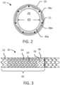
- FIG. 1 shows a diametrically adjustable endoprosthesis 10, according to some embodiments.
- the endoprosthesis 10 includes a stent 12, also described as a stent element or support.
- the stent 12 has a first segment 14 and a second segment 16.
- a base graft 18, also described as a first graft portion, a cover or a liner is provided along the length of the first segment 14, while a portion of the second segment 16 extends beyond the base graft 18 and is left largely uncovered.
- the terms "graft,” “cover,” and “liner” are used interchangeably herein, and are not meant to require a certain relative position with respect to the stent 12.
- a “liner” may surround the stent 12, a “cover” may be received entirely within the stent 12, and a “lined region” corresponds to a portion of an endoprosthesis including a graft layer, regardless of whether the graft resides inside, outside, sandwiches, or is otherwise positioned relative to a stent element.
- the endoprosthesis 10 also includes a controlled expansion element 20, also described as a second graft portion. In FIGS. 1 and 3 , the controlled expansion element 20 is called out with cross-hatching in FIGS. 1 and 3 for ease of visualization.
- the controlled expansion element 20 extends along at least a portion of the base graft 18 and optionally enhances or augments one or more functions of the base graft 18, for example serving as a functional graft component of the base graft 18.
- the endoprosthesis 10 has a proximal end 22 and a distal end 24 and defines an inner lumen 26 ( FIG. 2 ).
- radiopaque markers are provided along the length of the endoprosthesis 10 as desired.
- the assembled endoprosthesis 10 includes a graft-lined region 28 and an unlined region 30, although in other designs the entire endoprosthesis 10 is lined and is characterized by an absence of an unlined region.
- the graft-lined region 28 corresponds to an intrahepatic region and the unlined region 30 corresponds to a portal region.
- the graft-lined region 28 defines a first end portion 32, a middle portion 34, and a second end portion 36.
- the border between the graft-lined region 28 and the unlined region 30 is indicated by a circumferential radiopaque gold marker band 38 proximate, or just proximal to, the border.
- An additional radiopaque gold marker is optionally located on the proximal end 22 of the endoprosthesis 10.
- the diametrically controlled portion of the endoprosthesis 10 extends for less than an entire length of the endoprosthesis 10, and in particular less than a full length of the graft-lined region 28, although in other embodiments the controlled expansion extends for any desired length, including the full endoprosthesis length as desired.
- the middle portion 34 corresponding to the controlled expansion portion of the endoprosthesis 10 has a first flared end 40, a central portion 42, and a flared second end 44.
- the first and second flared ends 40, 44 taper in different directions and at taper angle relative to the longitudinal axis of the endoprosthesis 10 (e.g., at a relative angle from about 10-80 degrees, including any value therebetween, such as about 60 degrees).
- the flared ends 40, 44 are shown with generally linear tapers, curved tapers, re-curved tapers, combined linear and curved tapers, and others are contemplated.
- the first and second flared ends 40, 44 help provide a smooth transition to the adjacent, first and second end portions 32, 36 when the endoprosthesis 10 is in an unconstrained state following initial deployment.
- the central portion 42 is shown as having a substantially uniform diameter, the central portion 42 optionally includes one or more tapers as desired, as can any of the other portions of the endoprosthesis 10.
- the middle portion 34 of the graft-lined region 28 is constrained with the controlled expansion element 20 such that the endoprosthesis 10 exhibits an initial diametric expansion limit at the middle portion 34 to which the endoprosthesis 10 is deployed and which the endoprosthesis maintains prior to one or more subsequent mechanical adjustment steps.
- the expansion element 20 causes the middle portion 34 to take on a dog-bone shape or hourglass shape, although any of a variety of shapes are contemplated.
- the endoprosthesis 10 defines a minimum inner diameter (ID) at a boundary 46 between the central portion 42 and the first flared end 40.
- the diameter of the endoprosthesis 10 in the middle portion 34 is smaller than the adjacent portions of the endoprosthesis 10 because the controlled expansion element 20 diametrically constrains self-expansion of the stent 12, but is able to be mechanically adjusted by a distensive force (e.g., using a balloon catheter) to allow diametric adjustment.
- a distensive force e.g., using a balloon catheter
- the controlled expansion element 20 was removed from the endoprosthesis 10 the stent 12 and base graft 18 would tend to self-expand to a maximum diametric expansion limit.
- the stent-graft 12, 18 is configured to expand to a maximum diameter (e.g., the manufactured diameter of the stent-graft) at which point further expansion is significantly resisted (e.g., resistance of 1000 ATM or more) and may even result in failure if an attempt to force the stent-graft 18 beyond that diameter is attempted.
- the stent 12, the graft 18, or the combination of the stent-graft 12, 18 can be configured to set this maximum diametric adjustment limit, beyond which the endoprosthesis 10 is not intended to be diametrically adjusted.
- middle portion 34 will expand correspondingly, up to a diameter of the adjacent, first and second end portions 32, 36 (e.g., as shown in FIG. 3 ) which represent the fully expanded diameter of the stent--graft 12, 18.
- FIG. 3 shows the endoprosthesis 10 expanded to a maximum diametric expansion limit imparted by the remainder of the endoprosthesis 10, for example imparted by the base graft 18.
- the lined region 28 has a maximum diametric expansion limit corresponding to the base graft 18 having a continuous cylindrical profile through the first end portion 32, the middle portion 34, and the second end portion 36.
- the stent-graft 12, 18 may have an "as manufactured" diameter, beyond which the stent-graft 12, 18 is not meant to expand in typical use, whether under physiological conditions or by balloon expansion.
- the ID of the endoprosthesis 10 upon deployment at the middle portion 34 is approximately 8 mm and is expandable to approximately 10 mm. In some examples, the ID of the endoprosthesis 10 at the middle portion 34 (e.g., as measured at the minimum ID location 46) is expandable by 12% to 40%, for example. In still other embodiments, the endoprosthesis 10 at the middle portion 34 is expandable greater than 40%, such as up to 70% or even more.
- the endoprosthesis 10 would typically have dimensions as follows: a length of about 5 to 12 cm, with a length of about 6 to 10 cm being more typical; a deployed diameter of about 5 to 14 mm, with a diameter of about 8 to 12 mm being more typical; and a total wall thickness of about 0.1 to 1.0 mm, with about 0.1 to 0.6 mm being more typical. While the dimension "diameter” is used herein, it should be understood that this dimension is intended to define an average cross-sectional dimension and is not intended to limit designs to circular cross-sectional shapes. Moreover, as shown in FIG. 1 , the endoprosthesis 10 may be configured to exhibit multiple average cross-section dimensions along the length of the endoprosthesis 10, including tapers along different portions of the endoprosthesis 10.
- the endoprosthesis 10 itself has a compacted dimension suitable for endoluminal deployment, such as less than or equal to 16 French (5.3 mm), although a variety of dimensions are contemplated depending upon the treatment in which it is applied.
- the endoprosthesis 10 and its deployment apparatus in order to be delivered percutaneously, have a diameter of less than about 13 French (4.3 mm), for example, although a variety of dimensions are contemplated.
- "French" measurements as used herein define the size of a hole through which a device will pass. For example, a device with a measurement of "10 French” will pass through a 10 French hole (which has a diameter of 3.3 mm). Again, the device need not have a circular cross-section in order to pass through a circular 10 French hole so long as the hole is large enough to accommodate the widest cross-sectional dimension of the endoprosthesis 10.
- the first segment 14 of the endoprosthesis 10 will typically comprise about 50 to 90 percent of the entire length of the endoprosthesis 10. Accordingly, the first segment 14 will typically be about 4 to 8 cm in length and the second segment 16 will typically be about 1 to 3 cm in length, although a variety of dimensions are contemplated.
- the middle portion 34 of the graft lined region 28 corresponding to the controlled expansion element 20 typically has a total length of about 1 to 11.5 cm, where the first flared end 40 has a length of about 0.25 to 1.5 cm, more typically 0.5 cm, the central portion 42 has a length of about 0.5 to 8.5 cm, with 1.5 to 5.5 cm being more typical, and the flared second end 44 has a length of about 0.25 to 1.5 cm, with 0.5 cm being more typical, although a variety of dimensions are contemplated.
- the stent 12 optionally includes any number of segments and configurations, according to various embodiments.
- the first segment 14 has an undulating, helical stent pattern, although other configurations are contemplated.
- the second segment 16 optionally employs a different stent pattern from that of the first segment 14.
- the second segment 16 is shown with an interlocked (or "chain-linked") stent pattern that helps prevent the second segment 16 from excessively longitudinally elongating beyond a predetermined desired length, although other configurations are contemplated.
- a single wire is employed for the second segment 16, where the wire is wrapped from the cover 18 to a distal end 24 of the endoprosthesis 10 and then back to the cover 18 such that the wire terminates within the cover 18 and avoids having a loose end of the wire exposed at the distal end 24 of the endoprosthesis 10.
- a single wire is wrapped from the first segment 14 to the distal end 24 of the endoprosthesis 10 and then back to the first segment 14.
- the wire is provided with a second undulated pattern along a first pass and a third undulating pattern, interlocking with the second undulating pattern along a second pass.
- interlocked stent pattern also imparts columnar support when the device is in a radially compressed configuration and less so when it is deployed.
- suitable stent patterns and associated methods of manufacture for the first and second segments are also described in U.S. Patent 6,673,102 to Vonesh et al.
- the first and second segments 14, 16 of the stent 12 may be formed from a variety of wire materials, including stainless steel, nickel-titanium alloy (nitinol), tantalum, elgiloy, various polymer materials, such as poly(ethylene terephthalate) (PET) or polytetrafluoroethylene (PTFE), or bioresorbable materials, such as levorotatory polylactic acid (L-PLA) or polyglycolic acid (PGA).
- the stent 12 is self-expanding and exerts a self-expansion force on the endoprosthesis 10 when constrained.
- the first and second segments 14, 16 of the stent 12 are formed of superelastic materials, such as nitinol metal, that will withstand tight compression in a compacted configuration (diameter) and then self-expand to a deployed configuration (diameter) once released in place, such as those described in U.S. Patent 6,673,102 to Vonesh et al.
- the endoprosthesis 10 is generally described as including a self-expanding stent 12, it should be understood that the stent 12 may include one or more balloon expandable portions (e.g., the second segment 16 may be balloon expandable) or the entire stent 12 may be balloon expandable with the endoprosthesis 10 being free of any self-expanding stent components.
- the controlled expansion element 20 is optionally employed with a balloon expandable stent-graft and allows diametric adjustment beyond an initial deployment diameter through a plurality of adjusted diameters up to a maxim diametric expansion limit of the balloon expandable stent-graft.
- the cover 18 helps provide the endoprosthesis 10 with a flow lumen.
- the cover 18 performs a number of functions in the endoprosthesis 10, including preventing extrusion of liver tissue through the stent 12, maintaining the maximum diametric dimensions of the endoprosthesis 10, preventing uncontrolled elongation of the stent 12, reducing or eliminating bile from permeating into the shunt, and facilitating bending without kinking, for example.
- the controlled expansion element 20 optionally enhances or augments one or more functions of the base graft 18 beyond diametric adjustability.
- the controlled expansion element 20 optionally provides enhanced impermeability performance, longitudinal strength, or others.
- the preferred material for the base graft 18 includes a base tube 48a, an inner film 48b, and an outer film 48c.
- the base tube 48a may be a fluoropolymer material and especially expanded polytetrafluoroethylene (PTFE).
- the inner film 48b is also optionally a fluoropolymer, and especially expanded PTFE.
- the base tube 48a may be an extruded, thin-walled expanded PTFE base tube and the inner film 48b a plurality of layers of expanded PTFE film helically wrapped over the base tube.
- the outer film 48c is also optionally a fluoropolymer, such as a porous composite film of FEP and expanded PTFE.
- base tube 48a, inner film 48b, and outer film 48c are described in U.S. Patent 6,673,102 to Vonesh et al.
- the base graft 18 is substantially continuous and uninterrupted in that the wall does not have any apertures or holes of sufficient size to remain patent in vivo, although grafts 18 with apertures or openings (not shown) configured to remain patent in vivo are also contemplated in other applications.
- the inner and/or outer film layers 48b, 48c optionally lend increased radial, or hoop strength to the base graft 18 and help to set the maximum diametric expansion limit of the stent-graft 12, 18 at the as manufactured diameter of the stent-graft 12, 18.
- the stent 12 and the base graft 18 are secured together to provide a stent-graft 12, 18.
- the first segment 14 is secured to the base graft 18 and an end of the second segment 16 is optionally secured to the base graft 18 and/or first segment 14.
- one or more layers of the base graft 18 is positioned interior of the stent 12 to define the inner lumen 26, although the base graft 18 is optionally positioned entirely outside of the stent element 12 or with the stent 12 embedded into the base graft 18, for example.
- the second segment 16 of the stent 12 is left uncovered, with an end of the second segment 16 secured to the base graft 18 (e.g., a single "row") and a remainder of the second segment 16 extending from the base graft 18.
- the base graft 18 e.g., a single "row”
- none of the interstices of the second segment 16 are covered such that fluid is able to flow through the interstices.
- the second segment 16 is left uncovered to facilitate perfusion of portal venous branches via blood flow through the interstices of the second segment 16.
- the base graft 18 is preferably attached to the stent 12 by bonding or otherwise attaching the two together through use of a suitable adhesive, such as fluorinated ethylene propylene (FEP), polyurethane, cyanoacrylates, or others. Additionally, the materials may be bonded or otherwise attached together through heat treatment (such as, sintering of the materials together) or through use of a wrap (for instance a tube, tape, or membrane) around the outside of the stent and cover (either continuous or discontinuous) that is adhered through either a thermoplastic or thermoset adhesive to the stent and cover.
- a suitable adhesive such as fluorinated ethylene propylene (FEP), polyurethane, cyanoacrylates, or others.
- FEP fluorinated ethylene propylene
- the materials may be bonded or otherwise attached together through heat treatment (such as, sintering of the materials together) or through use of a wrap (for instance a tube, tape, or membrane) around the outside of the stent and
- the stent 12 may also be coated with a thermopolymer or thermoset adhesive and the cover bonded or otherwise attached by reflowing or setting the polymer coating.
- the stent 12 and base graft 18 are mechanically attached (e.g., using sutures).
- the stent 12 is positioned as desired over a portion of the base graft 18 (e.g., over a base tube and layers of wrapped expanded PTFE) and a porous composite film of FEP and expanded PTFE is wrapped over the construction with the side of the film containing FEP toward the lumen of the base graft 18.
- the first segment 14 of the stent 12 is optionally coated with an adhesive, such as FEP, placed around the base tube 48a and inner film 48b, and is in turn covered by the outer film 48c.
- the assembly can then be heated at one or more points in the assembly process to bond or otherwise attach the various layers together as described in U.S. Patent 6,673,102 to Vonesh et al.
- the controlled expansion element 20 is configured to be mechanically adjustable under pressure greater than typical biological pressures (e.g., typically circulatory pressures) and any expansion force exerted by the stent 12.
- the controlled expansion element 20 is optionally mechanically adjustable by causing controlled expansion material forming one or more portions of the element 20 to yield or plastically deform, by causing reorganization of a fibrillary or other microstructure of such controlled expansion material, by release of fasteners or folds of the element 20, or other mechanical adjustment of the controlled expansion element 20.
- the pressure required to mechanically adjust the controlled expansion element 20 is greater than typical physiologic conditions (e.g., typical maximum blood pressures) such that the controlled expansion element 20 is able to maintain the adjusted diameter at less than a pressure that would tend to cause the stent-graft 12, 18 to catastrophically fail by exceeding the maximum diametric expansion limit of the stent-graft 12.
- the controlled expansion element 20 is preferably configured to maintain a diameter to which it is mechanically adjusted without substantial diameter creep or spontaneous diametric expansion over time under typical biological conditions.
- the controlled expansion element 20 optionally includes one or more layers and may be formed from a variety of materials, including fluoropolymer materials such as the distensible, expanded PTFE tube described in U.S.
- the controlled expansion element 20 is formed of controlled expansion material including a bilayer compressed composite material formed of layers each including unsintered expanded PTFE and a stabilizing layer, such as a continuous layer of FEP.
- the unsintered aspect of the expanded PTFE contributes to the expandability of the controlled expansion material.
- Unsintered expanded PTFE can be manufactured by extrusion followed by concurrent heating and stretching.
- Sintered expanded PTFE is manufactured by extrusion, concurrent heating and stretching, and sintering (heating to above the PTFE crystalline melting point temperature). Because unsintered expanded PTFE is heated to a lesser extent than sintered expanded PTFE, unsintered expanded PTFE material has greater conformability and greater stretchability than sintered expanded PTFE.
- the unsintered expanded PTFE has nonbent fibrils that can elongate approximately 40% or more before rupture, for example.
- one or more wraps of the unsintered expanded PTFE/FEP composite material are overlapped to comprise the controlled expansion element 20.
- the FEP bonds together the multiple wraps of unsintered expanded PTFE to create a monolithic sleeve structure, for example, although a variety of configurations are contemplated (e.g., rings, collars, cylinder segments).
- the controlled expansion element is optionally formed by cutting the unsintered and compressed, or densified, controlled expansion material into strips that are helically wound onto a cylindrical mandrel. One or more layers are formed in one or more passes to form a sleeve. In some embodiments, the material is wound so that the FEP side of the controlled expansion material faces outward.
- any number of additional layers may also be applied over the controlled expansion element 20 as desired at any point in the process of forming the controlled expansion element 20 and/or during assembly of the endoprosthesis 10.
- the diameter of the cylindrical mandrel determines the initial inner diameter of the controlled expansion element 20.
- the controlled expansion element 20 is then heated, while still on the mandrel, to activate the FEP adhesive.
- the heat causes the FEP to flow, thereby creating a functionally unitary multi-layered sleeve of unsintered expanded PTFE.
- the controlled expansion element 20 is removed from the mandrel and the ends of the controlled expansion element 20 are trimmed to create a sleeve of a desired length.
- the controlled expansion element 20 also optionally has a substantially continuous and uninterrupted wall characterized by the absence of apertures or holes configured to remain patent in vivo.
- the controlled expansion element 20 is placed onto an underlying portion of the endoprosthesis 10, such as the stent 12 and base graft 18 (collectively, "stent-graft 12, 18"), although a variety of configurations are contemplated, including the controlled expansion element 20 being secured inside of the stent-graft 12, 18.
- the pre-assembled stent-graft 12, 18 is pulled through a loading funnel and into a tube with an outer diameter that is smaller than the inner diameter of the controlled expansion element 20.
- the tube containing the stent-graft 12, 18 is placed within the controlled expansion element 20 and the tube is removed from the stent-graft 12, 18.
- the stent-graft 12, 18 Upon emergence from the tube, the stent-graft 12, 18 self-expands to conform to the inner diameter of the controlled expansion element 20.
- the controlled expansion element 20 has a length selected to be shorter than the base graft 18 such that a partial segment of the base graft 18 corresponding to the middle portion 34 is covered by the controlled expansion element 20.
- the controlled expansion element 20 is coupled to a portion of the remaining endoprosthesis 10 mechanically (e.g., by interference fit, friction fit, sutures, or others).
- the controlled expansion element 20 is alternatively or additionally secured to the endoprostheses using a bonding agent (e.g., an adhesive such as FEP) between the endoprosthesis and the controlled expansion element 20.
- the bonding agent is optionally applied as a continuous layer or a discontinuous layer over substantially all the interface between the controlled expansion element 20 and the remaining endoprosthesis 10 or over only one or more portions of the interface between the controlled expansion element 20 and the remaining endoprosthesis 10.
- the controlled expansion element 20 is alternatively or additional coupled to the graft by a heating operation (e.g., by a global sintering or localized sintering at one or more selected portions of the interface between the controlled expansion element 20 and the remaining endoprosthesis 10).
- an inner diameter set process is performed for coupling the controlled expansion element 20 to the stent-graft 12, 18 prior to collapsing the endoprosthesis 10 into a delivery configuration.
- Some set processes include pulling the stent-graft 12, 18 with controlled expansion element 20 placed on it over a mandrel (not shown) having a larger outer diameter than the initial ID of the assembled endoprosthesis 10.
- the mandrel has an outer diameter (OD) corresponding to the shape of the middle portion 34 and the desired initial diametric expansion limit of the endoprosthesis 10 (the ID to which the endoprosthesis self-expands to in vivo following deployment prior to mechanically adjusting the controlled expansion element 20).
- the controlled expansion element 20 would cause the endoprosthesis 10 to have an ID less than 8 mm and the OD of the mandrel would be 8 mm such that after the set process the controlled expansion element 20 is mechanically adjusted and the endoprosthesis 10 exhibits an 8 mm ID.
- the mandrel has flared ends corresponding to the ends of the controlled expansion element 20 to provide flared ends to the controlled expansion element 20 and a smoother transition between the segment of the stent-graft 12, 18 constrained by the controlled expansion element 20 and adjacent segments of the stent graft 12, 18.
- the mandrel may have a continuous diameter between flared ends, any number of flares, tapers, curves, or other features are contemplated for imparting corresponding features to the portion of the endoprosthesis 10 corresponding to the controlled expansion element 20.
- the set process causes the controlled expansion element 20 to conform to the outer surface of the endoprosthesis 10, which is believed to help hold the controlled expansion element 20 in place through subsequent processing, deployment, and implantation of the endoprosthesis 10 without the use of thermal and/or adhesive bonding.
- the absence of thermal and/or adhesive bonding or other attachment along at least a portion of the interface between the controlled expansion element 20 and the stent-graft 12, 18 defines a sliding interface that helps allow the controlled expansion element 20 to slide on the surface of the stent-graft 12, 18 when ballooned, thus limiting the amount of foreshortening the controlled expansion element 20 translates to the stent-graft 12, 18.
- an interference fit between the stent graft 12, 18 and controlled expansion element 20 provides a sliding interface between the components, according to some embodiments.
- the sliding interface between the controlled expansion element 20 and the stent-graft 12, 18 permits at least a portion of the controlled expansion element 20 to change in longitudinal dimension (e.g., contract during radial expansion) at a different rate than the stent-graft 12, 18 at the sliding interface.
- a portion of the interface between the controlled expansion element 20 and stent-graft 12, 18 is adhesively bonded.
- a fluoropolymer adhesive is used, such as tetrafluoroethylene (TFE) and perfluoromethyl vinyl ether (PMVE) described in U.S. Patent 7,462,675 to Chang et al. , FEP (fluorinated ethylene propylene), or PFA (perfluoroalkylvinyl ether/tetrafluoroethylene copolymer), for example.
- the adhesive is optionally applied on the inner diameter of the controlled expansion element 20, for example at each end of the controlled expansion element 20 but not at the central region, although a variety of configurations are contemplated.
- the controlled expansion element 20 is adhered along the entire interface or a majority of the interface the controlled expansion element 20 forms with the remaining endoprosthesis 10.
- the controlled expansion element 20 is everted prior to applying it over the stent-graft 12, 18.
- the eversion of the controlled expansion element 20 repositions the FEP that was previously on the outer diameter (abluminal surface) of the controlled expansion element 20 to the inner diameter (luminal surface).
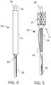
- FIGS. 4 and 5 illustrate a distal portion of a delivery system 50 for delivering and deploying the endoprosthesis 10 to a desired location for treatment, according to some embodiments.
- the delivery system 50 is a catheter-based, multi-staged deployment system including various features such as those described in U.S. Patent 6,673,102 to Vonesh et al. As shown, the delivery system 50 includes an introducing (or packaging) constraint 52, a delivery constraint 54, a distal catheter shaft 56, and a proximal catheter shaft 58 (partially shown and extending proximally in FIGS. 4 and 5). FIGS. 4 and 5 also show a cut off view of a deployment line 60 attached to a delivery constraint 54 having a sufficient length to be externally manipulated to release the delivery constraint 54 from the endoprosthesis 10. During endovascular deployment, the delivery system 50 is passed through an introducing catheter (not shown) extending to a target location in the body of a patient.
- the introducing constraint 52 is a tube slidably received over the endoprosthesis and functions to maintain the second segment 16 of the stent 12 in a compacted, delivery profile. As described below, the introducing constraint 52 assists with transferring the endoprosthesis 10 into an outer catheter tube (e.g., an introducer) with the second segment 16 maintained in the compacted, delivery profile in the catheter tube (not shown).
- an outer catheter tube e.g., an introducer
- FIG. 4 corresponds to a state in which the endoprosthesis 10 is fully constrained at a delivery diametrical dimension and FIG. 5 shows the endoprosthesis 10 partially deployed, and in particular with the second segment 16 of the stent 12 allowed to deploy (e.g., via self-expansion).
- the second segment 16 of the endoprosthesis 10 When the second segment 16 of the endoprosthesis 10 is unconstrained, the second segment 16 will expand to close to its fully deployed diameter. The remainder of the endoprosthesis 10, however, is contained within a delivery constraint 54 at a delivery diametrical dimension.
- the constrained endoprosthesis 10 will pass from the introducing constraint 52 into a catheter tube of approximately equal inner diameter (not shown) extending past the ultimate deployment site. Deployment of the second segment 16 will occur when the endoprosthesis 10 is extended from the catheter tube (not shown) at the deployment site (e.g., by retracting the catheter tube, extending the second segment 16 from the catheter tube, or
- the delivery constraint 54 maintains the first segment 14, base graft 18, and controlled expansion element 20 in a collapsed state at a delivery diametrical dimension.
- the delivery constraint 54 also described as a constraining element, comprises a plurality of interwoven threads that are capable of being unwoven upon pulling the deployment line 60 at which point the delivery constraint 54 is deconstructed and pulled from the away from the endoprosthesis 10 through the delivery system 50.
- the deployment line 60 extends through the proximal shaft 58 toward a proximal end of the system 50 where it can be manipulated externally to a patient by a user. Examples of knit, or interwoven delivery constraints are disclosed in U.S. Patent 6,673,102 to Vonesh et al.
- the delivery constraint 54 is a sheet of material having two ends secured together that are able to be released upon actuation of a deployment line.
- the delivery constraint 54 is a distal end of a catheter sheath that is able to be actuated and removed from the stent-graft 12, 18 to permit self-expansion to the initial deployed state of the stent-graft 12, 18.
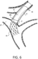
- FIG. 6 shows the endoprosthesis deployed in an intrahepatic portosystemic shunt.
- a catheter tube (not shown) is advanced into a portal vein P of a patient though a pathway formed through the liver from the haptic vein H to the portal vein P.
- a compacted endoprosthesis 10, mounted within the introducing constraint 52 is inserted into a proximal end of the catheter tube by manipulating the proximal shaft 58 to cause the second segment 16 to become transferred from the introducing constraint 52 into the catheter tube.
- the endoprosthesis 10 is then advanced through the catheter tube through the inferior vena cava, the hepatic vein H, the intrahepatic tract (shunt) formed in the liver, and well into the portal vein P.
- Radiopaque tip 64 can be aligned with the end of the catheter tube.
- Radiopaque markers associated with the endoprosthesis 10, such as the band 38 ( FIG. 1 ) can be used to position the end of the base graft 18 adjacent to the intrahepatic juncture site Y such that the second segment 16 extends into the portal vein P.
- the catheter tube is withdrawn proximally, which permits the second segment 16 to fully expand within the portal vein P.
- the proximal catheter shaft 58 is then withdrawn through the catheter tube to seat the endoprosthesis 10 so that the unlined portal region is in the portal vein P of the liver and the graft-lined region 28 is engaged with the ostium of the tunnel in which the endoprosthesis 10 is being deployed, corresponding to the intrahepatic juncture Y.
- Alignment can be confirmed fluoroscopically by correct orientation of one or more radiopaque markers.
- the endoprosthesis 10 is optionally deployed into the lumen of a previously deployed endoprosthesis (not shown) forming the shunt to augment or correct the performance of a previously deployed endoprosthesis, for example.
- the delivery constraint 54 is removed by actuating deployment line 60, allowing the first segment 14 of the endoprosthesis 10 to enlarge in place in a tip-to-hub direction.
- the deployment procedure aligns the covered portion of the endoprosthesis 10 within the intrahepatic tract (shunt). Further, the uncovered second segment 16 permits blood flow both to enter the endoprosthesis 10 and to continue through the portal vein P. The result is that excess pressure can be relieved from the portal system (through the shunt formed by the endoprosthesis 10) without completely eliminating normal blood flow through portal vein P.
- FIG 6 illustrate the endoprosthesis expanded to the initial diametric expansion limit pre-set into the controlled expansion element 20. If desired, touch-up of the endoprosthesis 10 can be performed by subsequent balloon dilation of the endoprosthesis 10 at balloon diameters below those required to mechanically adjust the controlled expansion element 20 to an adjusted diameter.
- Some methods of forming an intrahepatic portosystemic shunt include positioning the endoprosthesis 10 in the liver of the patient at a delivery diametrical dimension.
- the endoprosthesis 10 is fully deployed such that the endoprosthesis self-expands in situ and is fully seated in the liver of the patient to form the intrahepatic portosystemic shunt, where the controlled expansion element 20 limits expansion of a partial segment of the stent-graft 12, 18 to an initial deployed diametrical dimension as shown in FIG. 6 .
- This limited expansion restricts fluid flow through the shunt and impacts the pressure gradient between the portal vein P and the systemic venous circulation.
- the first end portion 32 ( FIG. 1 ) and a second end portion 36 FIG.
- a user e.g., a clinician
- the user can apply a distending force on controlled expansion element 20, for example by using a balloon catheter 80 ( FIG. 7 ), to mechanically adjust the controlled expansion element 20 a desired amount (e.g., up to the maximum diametric expansion limit of the base graft 18, which is represented in solid lines in FIG. 6 ).
- FIG. 8 is a schematic illustration of dilation of a portion of the endoprosthesis 10 using the balloon catheter 80.
- the stent 12 and base graft 18 are indicated collectively as a layer.
- the entire middle portion 34 which corresponds to the controlled expansion portion of the endoprosthesis 10 need not be dilated or otherwise diametrically adjusted in a single step (e.g., where balloon length is less than the middle portion 34).
- the diameter of the segment of stent-graft 12, 18 corresponding to the controlled expansion element 20 is able to be adjusted to any diameter between the initial delivery expansion limit and the maximum expansion limit by selection of maximum balloon diameter and/or balloon pressure.
- the diameter e.g., including the minimum inner diameter (ID) at the location 46
- ID minimum inner diameter
- the controlled expansion element 20 maintains the endoprosthesis 10 at the enlarged diametrical dimension and does not permit creep of the ID under typical physiologic conditions.
- the controlled expansion element 20 helps the endoprosthesis 10 maintain the enlarged diametrical dimension to permit increased fluid flow through the shunt (e.g., up to the maximum diametric expansion limit of the base graft 18, which then limits any further expansion).
- Various methods of treatment include taking one or more pressure measurements and adjusting the endoprosthesis 10 according.
- portal hypertension may be assessed and treated using one or more of such pressure measurements and adjustments.
- Portal hypertension is an increase in the blood pressure within the portal venous system.
- Wedged hepatic venous pressure (WHVP) is used to estimate the portal venous pressure by reflecting not the actual hepatic portal vein pressure but the hepatic sinusoidal pressure.
- WHVP Wedged hepatic venous pressure
- HVPG hepatic venous pressure gradient
- HVPG hepatic venous pressure gradient
- a user takes at least one pressure measurement after fully deploying the endoprosthesis to determine the pressure gradient between the portal vein and the systemic venous circulation, determines that adjustment is needed, and adjusts the diameter of the partial segment of the base graft 18 corresponding to the controlled expansion element 20.
- Any number of subsequent pressure measurements and enlarging adjustments are contemplated as part of a single procedure or multiple procedures. For example, in some treatment methods at least 24 hours pass between one or more pressure measurements and/or adjustments of the endoprosthesis 10, or an even greater amount of time.
- a diametric adjustment may occur as a separate procedure from the initial delivery procedure and formation of the shunt or as a separate adjustment procedure subsequent to a prior diametric adjustment procedure (e.g., performed at a later day, month, or even year).
- the controlled expansion element 20 optionally includes one or more physical features, such as pleats, folds, or creases ( FIG. 8 ) that are selectively secured in a closed configuration (e.g., by a bonding agent or material) and which can later be opened or separated by application of a distending force, thereby allowing the features to expand to mechanically adjust the diameter of the controlled expansion element 20.
- FIG. 9 shows a controlled expansion element 120 usable with any of the various features described above in association with endoprosthesis 10.
- the controlled expansion element 120 is generally sleeve-like, or cylindrical in configuration, is mechanically adjustable at distending forces greater than typical physiologic conditions (e.g., blood pressure), and can correspond to the diametrically controlled portion of the endoprosthesis 10, which is not shown in FIG. 8 .
- the controlled expansion element 120 includes one or more layers forming a sleeve 122 that defines one or more expansion features 124 in the form of longitudinal pleats or folds.
- One or more securing elements 126 for example a tape material, such as ePTFE coated with FEP, secures the expansion features 124 in a closed state.
- the securing elements 126 Upon application of a distending force (e.g., balloon dilation), the securing elements 126 allow the expansion features 124 to expand (e.g., they plastically deform, break, or release) resulting in diametric adjustment of the diametrically controlled portion of the endoprosthesis 10.
- a distending force e.g., balloon dilation
Landscapes
- Health & Medical Sciences (AREA)
- Engineering & Computer Science (AREA)
- Biomedical Technology (AREA)
- Life Sciences & Earth Sciences (AREA)
- Veterinary Medicine (AREA)
- Public Health (AREA)
- General Health & Medical Sciences (AREA)
- Animal Behavior & Ethology (AREA)
- Heart & Thoracic Surgery (AREA)
- Transplantation (AREA)
- Vascular Medicine (AREA)
- Oral & Maxillofacial Surgery (AREA)
- Cardiology (AREA)
- Pulmonology (AREA)
- Gastroenterology & Hepatology (AREA)
- Ophthalmology & Optometry (AREA)
- Otolaryngology (AREA)
- Anesthesiology (AREA)
- Hematology (AREA)
- Prostheses (AREA)
- Media Introduction/Drainage Providing Device (AREA)
Claims (14)
- Diametrisch einstellbare Endoprothese (10), umfassend:ein Stent-Implantat, das einen Stent (12) und ein Basis-Implantat (18), das an dem Stent (12) fixiert ist, enthält, wobei das Basis-Implantat (18) ein erstes Ende und ein zweites Ende aufweist und das Stent-Implantat selbstexpandierend ist und eine Selbstexpansionskraft zeigt, wobei das Stent-Implantat eine maximale diametrische Expansionsgrenze aufweist; undein Element (20) mit kontrollierter Expansion, das eine durchgehende Wand aufweist, wobei das Element (20) mit kontrollierter Expansion eine anfängliche diametrische Expansionsgrenze aufweist und auf einen eingestellten Durchmesser in einem Bereich von Durchmessern zwischen der anfänglichen diametrischen Expansionsgrenze und der maximalen diametrischen Expansionsgrenze einstellbar ist, wenn es einer Expansionskraft zusätzlich zu der Selbstexpansionskraft des Stent-Implantats ausgesetzt ist, wobei das Element (20) mit kontrollierter Expansion dazu konfiguriert ist, den eingestellten Durchmesser unter physiologischen Bedingungen nach dem Entfernen der Expansionskraft beizubehalten, und das Stent-Implantat dazu konfiguriert ist, den Durchmesserbereich für den eingestellten Durchmesser auf die maximale diametrische Expansionsgrenze zu begrenzen,wobei das Element (20) mit kontrollierter Expansion eine gleitende Grenzfläche mit dem Stent-Implantat definiert, sodass während der diametrischen Expansion der Endoprothese (10) die gleitende Grenzfläche zwischen dem Element (20) mit kontrollierter Expansion und dem Stent-Implantat es ermöglicht, dass mindestens ein Abschnitt des Elements (20) mit kontrollierter Expansion sich in der Längsabmessung mit einer anderen Geschwindigkeit als das Stent-Implantat an der Gleitgrenzfläche ändert.
- Endoprothese (10) nach Anspruch 1, wobei die Endoprothese (10) ein inneres Lumen (26) aufweist, das dazu konfiguriert ist, biologisches Fluid zu transportieren, und wobei ferner das Basis-Implantat (18) das innere Lumen (26) der Endoprothese (10) definiert.
- Endoprothese (10) nach Anspruch 1, wobei das Element (20) mit kontrollierter Expansion bei der anfänglichen diametrischen Expansionsgrenze eine oder mehrere Abschrägungen im Durchmesser definiert.
- Endoprothese (10) nach Anspruch 1, wobei das Element (20) mit kontrollierter Expansion einen ersten Endabschnitt, einen zweiten Endabschnitt und einen Mittelabschnitt zwischen dem ersten und dem zweiten Endabschnitt aufweist, und wobei ferner bei der anfänglichen diametrischen Expansionsgrenze das Element (20) mit kontrollierter Expansion den ersten Endabschnitt, der sich nach außen zu einem ersten Durchmesser abschrägt, und den zweiten Endabschnitt, der sich nach außen zu einem zweiten Durchmesser abschrägt, und den Mittelabschnitt, der einen kleineren Durchmesser als der erste und der zweite Durchmesser aufweist, enthält.
- Endoprothese (10) nach Anspruch 1, wobei das Element (20, 120) mit kontrollierter Expansion eine Hülse (122) aus einem Material mit kontrollierter Expansion enthält, die dazu konfiguriert ist, sich beim Aufbringen der Expansionskraft zu verformen und den eingestellten Durchmesser unter physiologischen Bedingungen beizubehalten.
- Endoprothese (10) nach Anspruch 1, wobei das Basis-Implantat (18) eine Länge aufweist und das Stent-Implantat einen ausgekleideten Bereich (28) und einen nicht ausgekleideten Bereich (30) enthält, wobei der ausgekleidete Bereich (28) der Länge des Implantats (18) entspricht und der nicht ausgekleidete Bereich (30) unbedeckt bleibt.
- Endoprothese (10) nach Anspruch 1, wobei der Stent (12) einen Teil enthält, der ein Kettengliedmuster definiert, wobei der Teil dem nicht ausgekleideten Bereich (30) des Stent-Implantats entspricht.
- Endoprothese (10) nach Anspruch 1, wobei das Stent-Implantat ferner mit Innendruck expandiert wird, der durch einen aufblasbaren Ballon aufgebracht wird.
- Endoprothese (10) nach Anspruch 8, wobei der Innendruck auf einen diametrisch kontrollierten Abschnitt der Endoprothese (10) aufgebracht wird, um das Element (20) mit kontrollierter Expansion zu verformen.
- Endoprothese (10) nach Anspruch 9, wobei sich der diametrisch kontrollierte Abschnitt der Endoprothese (10) über weniger als eine Gesamtlänge des Stent-Implantats erstreckt.
- Endoprothese (10) nach Anspruch 1, wobei der Stent (12) einen ersten Implantatabschnitt und einen zweiten Implantatabschnitt enthält, der sich entlang mindestens eines Abschnitts des ersten Implantatabschnitts erstreckt, und wobei beim diametrischen Expandieren der diametrisch kontrollierte Abschnitt der Endoprothese (10) den zweiten Implantatabschnitt verformt.
- Endoprothese (10) nach Anspruch 11, wobei eine diametrische Expansion des diametrisch kontrollierten Abschnitts der Endoprothese (10) auf einen weiter vergrößerten Durchmesser, der größer als der eingestellte Durchmesser ist, erfolgt.
- Endoprothese (10) nach Anspruch 12, wobei das diametrische Expandieren des diametrisch kontrollierten Abschnitts der Endoprothese (10) auf eine maximale diametrische Expansionsgrenze durch den Stent (12) und den ersten Implantatabschnitt definiert ist.
- Endoprothese (10) nach Anspruch 1, wobei die Endoprothese (10) einen nicht ausgekleideten Bereich (30) enthält.
Priority Applications (1)
| Application Number | Priority Date | Filing Date | Title |
|---|---|---|---|
| EP23173714.9A EP4233806A3 (de) | 2016-04-21 | 2016-04-21 | Diametral einstellbare endoprothesen |
Applications Claiming Priority (1)
| Application Number | Priority Date | Filing Date | Title |
|---|---|---|---|
| PCT/US2016/028671 WO2017184153A1 (en) | 2016-04-21 | 2016-04-21 | Diametrically adjustable endoprostheses and associated systems and methods |
Related Child Applications (2)
| Application Number | Title | Priority Date | Filing Date |
|---|---|---|---|
| EP23173714.9A Division-Into EP4233806A3 (de) | 2016-04-21 | 2016-04-21 | Diametral einstellbare endoprothesen |
| EP23173714.9A Division EP4233806A3 (de) | 2016-04-21 | 2016-04-21 | Diametral einstellbare endoprothesen |
Publications (3)
| Publication Number | Publication Date |
|---|---|
| EP3445282A1 EP3445282A1 (de) | 2019-02-27 |
| EP3445282A4 EP3445282A4 (de) | 2019-11-27 |
| EP3445282B1 true EP3445282B1 (de) | 2023-06-28 |
Family
ID=60116284
Family Applications (2)
| Application Number | Title | Priority Date | Filing Date |
|---|---|---|---|
| EP23173714.9A Pending EP4233806A3 (de) | 2016-04-21 | 2016-04-21 | Diametral einstellbare endoprothesen |
| EP16899644.5A Active EP3445282B1 (de) | 2016-04-21 | 2016-04-21 | Diametral einstellbare endoprothesen |
Family Applications Before (1)
| Application Number | Title | Priority Date | Filing Date |
|---|---|---|---|
| EP23173714.9A Pending EP4233806A3 (de) | 2016-04-21 | 2016-04-21 | Diametral einstellbare endoprothesen |
Country Status (8)
| Country | Link |
|---|---|
| US (2) | US11229512B2 (de) |
| EP (2) | EP4233806A3 (de) |
| JP (2) | JP7248430B2 (de) |
| CN (1) | CN109069257B (de) |
| AU (1) | AU2016403450B2 (de) |
| CA (1) | CA3021860C (de) |
| ES (1) | ES2956016T3 (de) |
| WO (1) | WO2017184153A1 (de) |
Families Citing this family (35)
| Publication number | Priority date | Publication date | Assignee | Title |
|---|---|---|---|---|
| US10166128B2 (en) | 2011-01-14 | 2019-01-01 | W. L. Gore & Associates. Inc. | Lattice |
| US9839540B2 (en) | 2011-01-14 | 2017-12-12 | W. L. Gore & Associates, Inc. | Stent |
| US9283072B2 (en) | 2012-07-25 | 2016-03-15 | W. L. Gore & Associates, Inc. | Everting transcatheter valve and methods |
| US9931193B2 (en) | 2012-11-13 | 2018-04-03 | W. L. Gore & Associates, Inc. | Elastic stent graft |
| US9101469B2 (en) | 2012-12-19 | 2015-08-11 | W. L. Gore & Associates, Inc. | Prosthetic heart valve with leaflet shelving |
| US9144492B2 (en) | 2012-12-19 | 2015-09-29 | W. L. Gore & Associates, Inc. | Truncated leaflet for prosthetic heart valves, preformed valve |
| US9968443B2 (en) | 2012-12-19 | 2018-05-15 | W. L. Gore & Associates, Inc. | Vertical coaptation zone in a planar portion of prosthetic heart valve leaflet |
| US10842918B2 (en) | 2013-12-05 | 2020-11-24 | W.L. Gore & Associates, Inc. | Length extensible implantable device and methods for making such devices |
| US9827094B2 (en) | 2014-09-15 | 2017-11-28 | W. L. Gore & Associates, Inc. | Prosthetic heart valve with retention elements |
| WO2017184153A1 (en) * | 2016-04-21 | 2017-10-26 | W. L. Gore & Associates, Inc. | Diametrically adjustable endoprostheses and associated systems and methods |
| CA3071133C (en) | 2017-09-12 | 2023-02-28 | W.L. Gore & Associates, Inc. | Leaflet frame attachment for prosthetic valves |
| US10595874B2 (en) | 2017-09-21 | 2020-03-24 | W. L. Gore & Associates, Inc. | Multiple inflation endovascular medical device |
| JP7068444B2 (ja) | 2017-09-27 | 2022-05-16 | ダブリュ.エル.ゴア アンド アソシエイツ,インコーポレイティド | 拡張可能なフレームを備えた人工弁、並びに関連するシステム及び方法 |
| JP6875601B2 (ja) | 2017-09-27 | 2021-05-26 | ダブリュ.エル.ゴア アンド アソシエイツ,インコーポレイティドW.L. Gore & Associates, Incorporated | リーフレットが機械的にカップリングされた人工弁 |
| DE102017123461A1 (de) * | 2017-10-10 | 2019-04-11 | Jotec Gmbh | Expandierbares Gefäßimplantat |
| WO2019074607A1 (en) | 2017-10-13 | 2019-04-18 | W. L. Gore & Associates, Inc. | TELESCOPIC PROSTHETIC VALVE AND INSTALLATION SYSTEM |
| US20190117369A1 (en) * | 2017-10-25 | 2019-04-25 | Cook Medical Technologies Llc | Layered cover material and method of use thereof |
| AU2018362079B2 (en) | 2017-10-31 | 2021-09-16 | Edwards Lifesciences Corporation | Medical valve and leaflet promoting tissue ingrowth |
| JP7090156B2 (ja) | 2017-12-01 | 2022-06-23 | シー・アール・バード・インコーポレーテッド | 人工医療デバイス |
| US11026818B2 (en) * | 2018-04-23 | 2021-06-08 | Boston Scientific Scimed, Inc. | Stent with selectively covered region |
| US12042592B2 (en) * | 2018-10-19 | 2024-07-23 | Stan Batiste | AV flow restrictors |
| IT201900000981A1 (it) * | 2019-01-23 | 2020-07-23 | Giancarlo Salsano | Dispositivo endovascolare per fistole disfunzionali |
| WO2020155000A1 (en) * | 2019-01-31 | 2020-08-06 | Becton, Dickinson And Company | Mixed-frame intraluminal prosthesis and methods thereof |
| US10702407B1 (en) | 2019-02-28 | 2020-07-07 | Renata Medical, Inc. | Growth stent for congenital narrowings |
| US11497601B2 (en) | 2019-03-01 | 2022-11-15 | W. L. Gore & Associates, Inc. | Telescoping prosthetic valve with retention element |
| CN109953780A (zh) * | 2019-04-30 | 2019-07-02 | 靖海岭 | 一种tips手术用球囊镶嵌覆膜支架 |
| CN110215313B (zh) * | 2019-06-13 | 2021-03-09 | 吉林大学 | 心内科血管支架系统 |
| US20230050140A1 (en) * | 2020-01-20 | 2023-02-16 | Angiomed Gmbh & Co. Medizintechnik Kg | Stent Graft and Kit |
| TWI770801B (zh) * | 2020-03-09 | 2022-07-11 | 陳階曉 | 用於撐開目標部位的醫療裝置 |
| CN111643221A (zh) * | 2020-06-16 | 2020-09-11 | 郑州大学第一附属医院 | 一种直径能够自动调整的肝内门体分流支架 |
| CN114748227A (zh) * | 2021-04-28 | 2022-07-15 | 聚辉医疗科技(深圳)有限公司 | 输送器及血流导向支架系统 |
| CN112972082A (zh) * | 2021-05-12 | 2021-06-18 | 上海微创心脉医疗科技(集团)股份有限公司 | 一种医用支架 |
| CN113397762B (zh) * | 2021-05-31 | 2022-02-08 | 上海心瑞医疗科技有限公司 | 一种心房分流植入装置 |
| US12004939B1 (en) | 2022-12-09 | 2024-06-11 | Renata Medical, Inc. | Transcatheter growth devices and methods for Norwood, Glenn and Fontan therapy |
| CN117357316B (zh) * | 2023-12-06 | 2024-02-20 | 苏州美创医疗科技有限公司 | 一种覆膜支架及其制造方法 |
Citations (16)
| Publication number | Priority date | Publication date | Assignee | Title |
|---|---|---|---|---|
| US3962153A (en) | 1970-05-21 | 1976-06-08 | W. L. Gore & Associates, Inc. | Very highly stretched polytetrafluoroethylene and process therefor |
| US4096227A (en) | 1973-07-03 | 1978-06-20 | W. L. Gore & Associates, Inc. | Process for producing filled porous PTFE products |
| US4187390A (en) | 1970-05-21 | 1980-02-05 | W. L. Gore & Associates, Inc. | Porous products and process therefor |
| US4902423A (en) | 1989-02-02 | 1990-02-20 | W. L. Gore & Associates, Inc. | Highly air permeable expanded polytetrafluoroethylene membranes and process for making them |
| DE3918736A1 (de) | 1989-06-08 | 1990-12-13 | Christian Dr Vallbracht | Kunststoffueberzogene metallgitterstents |
| WO2001024733A1 (en) | 1999-10-01 | 2001-04-12 | Boston Scientific/Scimed Life Systems, Inc. | Balloon yielded delivery system and endovascular graft design for easy deployment |
| US6217609B1 (en) | 1998-06-30 | 2001-04-17 | Schneider (Usa) Inc | Implantable endoprosthesis with patterned terminated ends and methods for making same |
| US20010053929A1 (en) | 1998-12-09 | 2001-12-20 | Michael J. Vonesh | Multi-stage expandable stent-graft |
| US6361637B2 (en) | 1995-12-14 | 2002-03-26 | Gore Enterprise Holdings, Inc. | Method of making a kink resistant stent-graft |
| US20020198588A1 (en) | 1999-01-22 | 2002-12-26 | Armstrong Joseph R. | Covered endoprosthesis and delivery system |
| US6890350B1 (en) | 1999-07-28 | 2005-05-10 | Scimed Life Systems, Inc. | Combination self-expandable, balloon-expandable endoluminal device |
| US20060015171A1 (en) | 2004-07-16 | 2006-01-19 | Armstrong Joseph R | Deployment system for intraluminal devices |
| US20130204347A1 (en) | 2011-01-14 | 2013-08-08 | W. L. Gore & Associates, Inc. | Lattice |
| US20150005870A1 (en) | 2013-03-15 | 2015-01-01 | W. L. Gore & Associates, Inc. | Self-expanding, balloon expandable stent-grafts |
| US20170014228A1 (en) | 2013-11-26 | 2017-01-19 | Children's Medical Center Corporation | Expandable stent valve |
| US10610395B2 (en) | 2010-11-16 | 2020-04-07 | W. L. Gore & Associates, Inc. | Sleeves for expandable medical devices |
Family Cites Families (198)
| Publication number | Priority date | Publication date | Assignee | Title |
|---|---|---|---|---|
| US3953556A (en) | 1973-01-12 | 1976-04-27 | The United States Of America As Represented By The United States Energy Research And Development Administration | Method of preparing uranium nitride or uranium carbonitride bodies |
| DE2947743C2 (de) | 1978-11-30 | 1983-12-08 | Sumitomo Electric Industries, Ltd., Osaka | Einheitliches, poröses röhrenförmiges Gebilde aus Polytetrafluoräthylen |
| US5071609A (en) | 1986-11-26 | 1991-12-10 | Baxter International Inc. | Process of manufacturing porous multi-expanded fluoropolymers |
| US4816339A (en) | 1987-04-28 | 1989-03-28 | Baxter International Inc. | Multi-layered poly(tetrafluoroethylene)/elastomer materials useful for in vivo implantation |
| DE3879613T2 (de) | 1987-10-19 | 1993-10-07 | Gore & Ass | Schnellrückstellbares PTFE und Verfahren zu dessen Herstellung. |
| US5026513A (en) | 1987-10-19 | 1991-06-25 | W. L. Gore & Associates, Inc. | Process for making rapidly recoverable PTFE |
| US4877661A (en) | 1987-10-19 | 1989-10-31 | W. L. Gore & Associates, Inc. | Rapidly recoverable PTFE and process therefore |
| US4955899A (en) | 1989-05-26 | 1990-09-11 | Impra, Inc. | Longitudinally compliant vascular graft |
| US5064435A (en) | 1990-06-28 | 1991-11-12 | Schneider (Usa) Inc. | Self-expanding prosthesis having stable axial length |
| US5673102A (en) | 1991-02-22 | 1997-09-30 | Canon Kabushiki Kaisha | Image farming and microdevice manufacturing method and exposure apparatus in which a light source includes four quadrants of predetermined intensity |
| US5342305A (en) | 1992-08-13 | 1994-08-30 | Cordis Corporation | Variable distention angioplasty balloon assembly |
| US5628782A (en) | 1992-12-11 | 1997-05-13 | W. L. Gore & Associates, Inc. | Method of making a prosthetic vascular graft |
| EP0633053B1 (de) | 1993-01-25 | 1997-07-30 | Daikin Industries, Limited | Verfahren zur herstellung eines porösen films aus polytetrafluorethylen |
| WO1995005131A1 (en) | 1993-08-18 | 1995-02-23 | W.L. Gore & Associates, Inc. | A tubular intraluminal graft |
| US6027779A (en) | 1993-08-18 | 2000-02-22 | W. L. Gore & Associates, Inc. | Thin-wall polytetrafluoroethylene tube |
| WO1995009586A1 (en) | 1993-10-01 | 1995-04-13 | Emory University | Self-expanding intraluminal composite prosthesis |
| US5549663A (en) | 1994-03-09 | 1996-08-27 | Cordis Corporation | Endoprosthesis having graft member and exposed welded end junctions, method and procedure |
| EP0758953B1 (de) | 1994-05-06 | 2004-03-03 | IMPRA, INC., a subsidiary of C.R. BARD, INC. | Vorrichtung zur behandlung eines körpergefässes |
| US6013854A (en) | 1994-06-17 | 2000-01-11 | Terumo Kabushiki Kaisha | Indwelling stent and the method for manufacturing the same |
| WO1996007370A1 (en) | 1994-09-02 | 1996-03-14 | W.L. Gore & Associates, Inc. | An asymmetrical porous ptfe form and method of making |
| JP3298890B2 (ja) | 1994-09-02 | 2002-07-08 | ダブリュ.エル.ゴア アンド アソシエイツ,インコーポレイティド | 多孔質ポリテトラフルオロエチレン混合物 |
| CA2301351C (en) | 1994-11-28 | 2002-01-22 | Advanced Cardiovascular Systems, Inc. | Method and apparatus for direct laser cutting of metal stents |
| US6896696B2 (en) | 1998-11-20 | 2005-05-24 | Scimed Life Systems, Inc. | Flexible and expandable stent |
| US6451047B2 (en) | 1995-03-10 | 2002-09-17 | Impra, Inc. | Encapsulated intraluminal stent-graft and methods of making same |
| US5476589A (en) | 1995-03-10 | 1995-12-19 | W. L. Gore & Associates, Inc. | Porpous PTFE film and a manufacturing method therefor |
| US5534007A (en) | 1995-05-18 | 1996-07-09 | Scimed Life Systems, Inc. | Stent deployment catheter with collapsible sheath |
| US5766201A (en) | 1995-06-07 | 1998-06-16 | Boston Scientific Corporation | Expandable catheter |
| US5814405A (en) | 1995-08-04 | 1998-09-29 | W. L. Gore & Associates, Inc. | Strong, air permeable membranes of polytetrafluoroethylene |
| US5752934A (en) | 1995-09-18 | 1998-05-19 | W. L. Gore & Associates, Inc. | Balloon catheter device |
| US20060271091A1 (en) | 1995-09-18 | 2006-11-30 | Campbell Carey V | Balloon catheter device |
| US5868704A (en) | 1995-09-18 | 1999-02-09 | W. L. Gore & Associates, Inc. | Balloon catheter device |
| US6193745B1 (en) | 1995-10-03 | 2001-02-27 | Medtronic, Inc. | Modular intraluminal prosteheses construction and methods |
| US5824037A (en) * | 1995-10-03 | 1998-10-20 | Medtronic, Inc. | Modular intraluminal prostheses construction and methods |
| US6689162B1 (en) | 1995-10-11 | 2004-02-10 | Boston Scientific Scimed, Inc. | Braided composite prosthesis |
| US5788626A (en) | 1995-11-21 | 1998-08-04 | Schneider (Usa) Inc | Method of making a stent-graft covered with expanded polytetrafluoroethylene |
| US5843158A (en) | 1996-01-05 | 1998-12-01 | Medtronic, Inc. | Limited expansion endoluminal prostheses and methods for their use |
| US5747128A (en) | 1996-01-29 | 1998-05-05 | W. L. Gore & Associates, Inc. | Radially supported polytetrafluoroethylene vascular graft |
| JPH09241412A (ja) | 1996-03-07 | 1997-09-16 | Sumitomo Electric Ind Ltd | 延伸ポリテトラフルオロエチレンチューブとその製造方法 |
| US5843161A (en) | 1996-06-26 | 1998-12-01 | Cordis Corporation | Endoprosthesis assembly for percutaneous deployment and method of deploying same |
| US5769884A (en) | 1996-06-27 | 1998-06-23 | Cordis Corporation | Controlled porosity endovascular implant |
| US5749852A (en) | 1996-07-23 | 1998-05-12 | Medtronic, Inc. | Sheath system for autoperfusion dilatation catheter balloon |
| US6174329B1 (en) | 1996-08-22 | 2001-01-16 | Advanced Cardiovascular Systems, Inc. | Protective coating for a stent with intermediate radiopaque coating |
| US6261320B1 (en) | 1996-11-21 | 2001-07-17 | Radiance Medical Systems, Inc. | Radioactive vascular liner |
| US6010529A (en) | 1996-12-03 | 2000-01-04 | Atrium Medical Corporation | Expandable shielded vessel support |
| US6315791B1 (en) | 1996-12-03 | 2001-11-13 | Atrium Medical Corporation | Self-expanding prothesis |
| US5925061A (en) | 1997-01-13 | 1999-07-20 | Gore Enterprise Holdings, Inc. | Low profile vascular stent |
| US5957974A (en) | 1997-01-23 | 1999-09-28 | Schneider (Usa) Inc | Stent graft with braided polymeric sleeve |
| US5853419A (en) | 1997-03-17 | 1998-12-29 | Surface Genesis, Inc. | Stent |
| CA2424551A1 (en) | 1997-05-27 | 1998-11-27 | Schneider (Usa) Inc. | Stent and stent-graft for treating branched vessels |
| US6203536B1 (en) | 1997-06-17 | 2001-03-20 | Medtronic, Inc. | Medical device for delivering a therapeutic substance and method therefor |
| US6500174B1 (en) | 1997-07-08 | 2002-12-31 | Atrionix, Inc. | Circumferential ablation device assembly and methods of use and manufacture providing an ablative circumferential band along an expandable member |
| US6042606A (en) | 1997-09-29 | 2000-03-28 | Cook Incorporated | Radially expandable non-axially contracting surgical stent |
| US6161399A (en) | 1997-10-24 | 2000-12-19 | Iowa-India Investments Company Limited | Process for manufacturing a wire reinforced monolayer fabric stent |
| US5931865A (en) | 1997-11-24 | 1999-08-03 | Gore Enterprise Holdings, Inc. | Multiple-layered leak resistant tube |
| US6626939B1 (en) | 1997-12-18 | 2003-09-30 | Boston Scientific Scimed, Inc. | Stent-graft with bioabsorbable structural support |
| US6190406B1 (en) | 1998-01-09 | 2001-02-20 | Nitinal Development Corporation | Intravascular stent having tapered struts |
| US6488701B1 (en) | 1998-03-31 | 2002-12-03 | Medtronic Ave, Inc. | Stent-graft assembly with thin-walled graft component and method of manufacture |
| US6042588A (en) | 1998-03-03 | 2000-03-28 | Scimed Life Systems, Inc | Stent delivery system |
| US5935162A (en) | 1998-03-16 | 1999-08-10 | Medtronic, Inc. | Wire-tubular hybrid stent |
| JP4222655B2 (ja) | 1998-04-06 | 2009-02-12 | ジャパンゴアテックス株式会社 | 医療用チューブ |
| US6224627B1 (en) | 1998-06-15 | 2001-05-01 | Gore Enterprise Holdings, Inc. | Remotely removable covering and support |
| US6156064A (en) * | 1998-08-14 | 2000-12-05 | Schneider (Usa) Inc | Stent-graft-membrane and method of making the same |
| US7815763B2 (en) | 2001-09-28 | 2010-10-19 | Abbott Laboratories Vascular Enterprises Limited | Porous membranes for medical implants and methods of manufacture |
| US6755856B2 (en) | 1998-09-05 | 2004-06-29 | Abbott Laboratories Vascular Enterprises Limited | Methods and apparatus for stenting comprising enhanced embolic protection, coupled with improved protection against restenosis and thrombus formation |
| NO984143L (no) | 1998-09-09 | 2000-03-10 | Norsk Hydro As | Ny prosess for å fremstille overflatemodifiserende stoffer |
| US6350277B1 (en) | 1999-01-15 | 2002-02-26 | Scimed Life Systems, Inc. | Stents with temporary retaining bands |
| US7049380B1 (en) | 1999-01-19 | 2006-05-23 | Gore Enterprise Holdings, Inc. | Thermoplastic copolymer of tetrafluoroethylene and perfluoromethyl vinyl ether and medical devices employing the copolymer |
| US6673102B1 (en) | 1999-01-22 | 2004-01-06 | Gore Enterprises Holdings, Inc. | Covered endoprosthesis and delivery system |
| AU3289999A (en) * | 1999-02-10 | 2000-08-29 | Gore Enterprise Holdings, Inc. | Multiple-layered leak-resistant tube |
| US6245012B1 (en) | 1999-03-19 | 2001-06-12 | Nmt Medical, Inc. | Free standing filter |
| GB2352205A (en) | 1999-06-28 | 2001-01-24 | Nestle Sa | Chilled roller for moulding a food product |
| US6673107B1 (en) | 1999-12-06 | 2004-01-06 | Advanced Cardiovascular Systems, Inc. | Bifurcated stent and method of making |
| US6740962B1 (en) | 2000-02-24 | 2004-05-25 | Micron Technology, Inc. | Tape stiffener, semiconductor device component assemblies including same, and stereolithographic methods for fabricating same |
| US6756094B1 (en) | 2000-02-28 | 2004-06-29 | Scimed Life Systems, Inc. | Balloon structure with PTFE component |
| US6379382B1 (en) | 2000-03-13 | 2002-04-30 | Jun Yang | Stent having cover with drug delivery capability |
| US6436132B1 (en) | 2000-03-30 | 2002-08-20 | Advanced Cardiovascular Systems, Inc. | Composite intraluminal prostheses |
| US6352552B1 (en) | 2000-05-02 | 2002-03-05 | Scion Cardio-Vascular, Inc. | Stent |
| US7419678B2 (en) | 2000-05-12 | 2008-09-02 | Cordis Corporation | Coated medical devices for the prevention and treatment of vascular disease |
| US8252044B1 (en) | 2000-11-17 | 2012-08-28 | Advanced Bio Prosthestic Surfaces, Ltd. | Device for in vivo delivery of bioactive agents and method of manufacture thereof |
| US6554841B1 (en) | 2000-09-22 | 2003-04-29 | Scimed Life Systems, Inc. | Striped sleeve for stent delivery |
| US8690910B2 (en) | 2000-12-07 | 2014-04-08 | Integrated Vascular Systems, Inc. | Closure device and methods for making and using them |
| DE10061936A1 (de) | 2000-12-13 | 2002-07-04 | Valentin Kramer | Gegenstand aus ePTFE und Verfahren zum Herstellen desselben |
| US7083642B2 (en) | 2000-12-22 | 2006-08-01 | Avantec Vascular Corporation | Delivery of therapeutic capable agents |
| US20020161388A1 (en) | 2001-02-27 | 2002-10-31 | Samuels Sam L. | Elastomeric balloon support fabric |
| US6716239B2 (en) | 2001-07-03 | 2004-04-06 | Scimed Life Systems, Inc. | ePTFE graft with axial elongation properties |
| US20030055494A1 (en) | 2001-07-27 | 2003-03-20 | Deon Bezuidenhout | Adventitial fabric reinforced porous prosthetic graft |
| US7288105B2 (en) | 2001-08-01 | 2007-10-30 | Ev3 Endovascular, Inc. | Tissue opening occluder |
| US20030045923A1 (en) | 2001-08-31 | 2003-03-06 | Mehran Bashiri | Hybrid balloon expandable/self expanding stent |
| US6827737B2 (en) | 2001-09-25 | 2004-12-07 | Scimed Life Systems, Inc. | EPTFE covering for endovascular prostheses and method of manufacture |
| ATE471124T1 (de) | 2001-10-04 | 2010-07-15 | Neovasc Medical Ltd | Flussverringerndes implantat |
| US6541589B1 (en) | 2001-10-15 | 2003-04-01 | Gore Enterprise Holdings, Inc. | Tetrafluoroethylene copolymer |
| US6946173B2 (en) | 2002-03-21 | 2005-09-20 | Advanced Cardiovascular Systems, Inc. | Catheter balloon formed of ePTFE and a diene polymer |
| WO2003082076A2 (en) | 2002-03-25 | 2003-10-09 | Nmt Medical, Inc. | Patent foramen ovale (pfo) closure clips |
| US7789908B2 (en) | 2002-06-25 | 2010-09-07 | Boston Scientific Scimed, Inc. | Elastomerically impregnated ePTFE to enhance stretch and recovery properties for vascular grafts and coverings |
| US20040024448A1 (en) | 2002-08-05 | 2004-02-05 | Chang James W. | Thermoplastic fluoropolymer-coated medical devices |
| CN1678366B (zh) | 2002-08-23 | 2010-06-09 | 国立循环器病中心总长所代表的日本国 | 支架及其制造方法 |
| US7273492B2 (en) | 2002-08-27 | 2007-09-25 | Advanced Cardiovascular Systems Inc. | Stent for treating vulnerable plaque |
| US6878162B2 (en) | 2002-08-30 | 2005-04-12 | Edwards Lifesciences Ag | Helical stent having improved flexibility and expandability |
| JP4995420B2 (ja) | 2002-09-26 | 2012-08-08 | アドヴァンスド バイオ プロスセティック サーフェシーズ リミテッド | 高強度の真空堆積されたニチノール合金フィルム、医療用薄膜グラフト材料、およびそれを作製する方法。 |
| US7001425B2 (en) | 2002-11-15 | 2006-02-21 | Scimed Life Systems, Inc. | Braided stent method for its manufacture |
| US7105018B1 (en) | 2002-12-30 | 2006-09-12 | Advanced Cardiovascular Systems, Inc. | Drug-eluting stent cover and method of use |
| US9125733B2 (en) | 2003-01-14 | 2015-09-08 | The Cleveland Clinic Foundation | Branched vessel endoluminal device |
| US20070207816A1 (en) | 2003-02-24 | 2007-09-06 | Polaris Wireless, Inc. | Location Estimation of Wireless Terminals Based on Combinations of Signal-Strength Measurements and Geometry-of-Arrival Measurements |
| US7011646B2 (en) | 2003-06-24 | 2006-03-14 | Advanced Cardiovascular Systems, Inc. | Balloon catheter having a balloon with a thickened wall portion |
| US7967829B2 (en) | 2003-10-09 | 2011-06-28 | Boston Scientific Scimed, Inc. | Medical device delivery system |
| US7763011B2 (en) | 2003-12-22 | 2010-07-27 | Boston Scientific Scimed, Inc. | Variable density braid stent |
| EP1725186B1 (de) * | 2004-03-02 | 2016-05-25 | Boston Scientific Scimed, Inc. | Medizinprodukte mit metallfilmen und herstellungsverfahren dafür |
| US20050273149A1 (en) | 2004-06-08 | 2005-12-08 | Tran Thomas T | Bifurcated stent delivery system |
| US7794490B2 (en) | 2004-06-22 | 2010-09-14 | Boston Scientific Scimed, Inc. | Implantable medical devices with antimicrobial and biodegradable matrices |
| WO2006014592A1 (en) | 2004-07-07 | 2006-02-09 | Cook Incorporated | Graft, stent graft and method for manufacture |
| US7763065B2 (en) * | 2004-07-21 | 2010-07-27 | Reva Medical, Inc. | Balloon expandable crush-recoverable stent device |
| CN2768714Y (zh) * | 2004-11-22 | 2006-04-05 | 微创医疗器械(上海)有限公司 | 一种柔软的血管支架 |
| US8029563B2 (en) | 2004-11-29 | 2011-10-04 | Gore Enterprise Holdings, Inc. | Implantable devices with reduced needle puncture site leakage |
| US8262720B2 (en) | 2004-12-02 | 2012-09-11 | Nitinol Development Corporation | Prosthesis comprising dual tapered stent |
| US20060135985A1 (en) | 2004-12-21 | 2006-06-22 | Cox Daniel L | Vulnerable plaque modification methods and apparatuses |
| US20060161241A1 (en) | 2005-01-14 | 2006-07-20 | Denise Barbut | Methods and devices for treating aortic atheroma |
| US20060190070A1 (en) | 2005-02-23 | 2006-08-24 | Dieck Martin S | Rail stent and methods of use |
| US20060276883A1 (en) | 2005-06-01 | 2006-12-07 | Cook Incorporated | Tapered and distally stented elephant trunk stent graft |
| US7531611B2 (en) | 2005-07-05 | 2009-05-12 | Gore Enterprise Holdings, Inc. | Copolymers of tetrafluoroethylene |
| US7306729B2 (en) | 2005-07-18 | 2007-12-11 | Gore Enterprise Holdings, Inc. | Porous PTFE materials and articles produced therefrom |
| JP2009504345A (ja) | 2005-08-17 | 2009-02-05 | シー・アール・バード・インコーポレーテッド | 可変速度ステント送達システム |
| US8702778B2 (en) | 2005-10-14 | 2014-04-22 | W. L. Gore & Associates, Inc. | Device for deploying an implantable medical device |
| US8956400B2 (en) | 2005-10-14 | 2015-02-17 | Flexible Stenting Solutions, Inc. | Helical stent |
| EP1965730A4 (de) | 2005-12-30 | 2009-06-17 | Bard Inc C R | Stent mit bioresorbierbarem konnektor und entsprechende verfahren |
| US9681948B2 (en) | 2006-01-23 | 2017-06-20 | V-Wave Ltd. | Heart anchor device |
| EP1825824B1 (de) | 2006-02-24 | 2009-11-04 | National University of Ireland, Galway | Minimalinvasive intravaskuläre Behandlungsvorrichtung |
| US9622850B2 (en) | 2006-02-28 | 2017-04-18 | C.R. Bard, Inc. | Flexible stretch stent-graft |
| US8025693B2 (en) | 2006-03-01 | 2011-09-27 | Boston Scientific Scimed, Inc. | Stent-graft having flexible geometries and methods of producing the same |
| US8585753B2 (en) | 2006-03-04 | 2013-11-19 | John James Scanlon | Fibrillated biodegradable prosthesis |
| US8425584B2 (en) | 2006-04-21 | 2013-04-23 | W. L. Gore & Associates, Inc. | Expandable covered stent with wide range of wrinkle-free deployed diameters |
| US8721704B2 (en) | 2006-04-21 | 2014-05-13 | W. L. Gore & Associates, Inc. | Expandable stent with wrinkle-free elastomeric cover |
| US20070254012A1 (en) | 2006-04-28 | 2007-11-01 | Ludwig Florian N | Controlled degradation and drug release in stents |
| US9114194B2 (en) | 2006-05-12 | 2015-08-25 | W. L. Gore & Associates, Inc. | Immobilized biologically active entities having high biological activity following mechanical manipulation |
| US7785290B2 (en) | 2006-08-07 | 2010-08-31 | Gore Enterprise Holdings, Inc. | Non-shortening high angle wrapped balloons |
| US20080140173A1 (en) | 2006-08-07 | 2008-06-12 | Sherif Eskaros | Non-shortening wrapped balloon |
| US8882826B2 (en) | 2006-08-22 | 2014-11-11 | Abbott Cardiovascular Systems Inc. | Intravascular stent |
| WO2008028964A2 (en) | 2006-09-07 | 2008-03-13 | Angiomed Gmbh & Co. Medizintechnik Kg | Helical implant having different ends |
| AU2007299659B2 (en) | 2006-09-21 | 2011-09-29 | Mico Innovations, Llc | A specially configured and surface modified medical device with certain design features that utilize the intrinsic properties of tungsten, zirconium, tantalum and/or niobium |
| US20080097401A1 (en) | 2006-09-22 | 2008-04-24 | Trapp Benjamin M | Cerebral vasculature device |
| US8545545B2 (en) | 2006-10-18 | 2013-10-01 | Innovational Holdings Llc | Stent with flexible hinges |
| US20080097582A1 (en) | 2006-10-18 | 2008-04-24 | Conor Medsystems, Inc. | Stent with flexible hinges |
| US9622888B2 (en) | 2006-11-16 | 2017-04-18 | W. L. Gore & Associates, Inc. | Stent having flexibly connected adjacent stent elements |
| WO2008097589A1 (en) | 2007-02-05 | 2008-08-14 | Boston Scientific Limited | Percutaneous valve, system, and method |
| WO2008098252A2 (en) | 2007-02-09 | 2008-08-14 | Taheri Laduca Llc | Vascular implants and methods of fabricating the same |
| US8057531B2 (en) | 2007-06-29 | 2011-11-15 | Abbott Cardiovascular Systems Inc. | Stent having circumferentially deformable struts |
| US20100094405A1 (en) | 2008-10-10 | 2010-04-15 | Orbusneich Medical, Inc. | Bioabsorbable Polymeric Medical Device |
| US7988723B2 (en) | 2007-08-02 | 2011-08-02 | Flexible Stenting Solutions, Inc. | Flexible stent |
| US8679519B2 (en) | 2007-10-23 | 2014-03-25 | Abbott Cardiovascular Systems Inc. | Coating designs for the tailored release of dual drugs from polymeric coatings |
| US8317857B2 (en) | 2008-01-10 | 2012-11-27 | Telesis Research, Llc | Biodegradable self-expanding prosthesis |
| US8926688B2 (en) | 2008-01-11 | 2015-01-06 | W. L. Gore & Assoc. Inc. | Stent having adjacent elements connected by flexible webs |
| EP3789069B1 (de) | 2008-02-05 | 2024-04-03 | Silk Road Medical, Inc. | Interventionelles kathetersystem und verfahren |
| EP3915525A1 (de) | 2008-02-28 | 2021-12-01 | Medtronic, Inc. | Herzklappenprothesensysteme |
| EP2106820A1 (de) | 2008-03-31 | 2009-10-07 | Torsten Heilmann | Dehnbare, biokompatible Beschichtungen mit einer biologisch aktiven Substanz |
| ES2389274T3 (es) | 2008-07-17 | 2012-10-24 | W.L. Gore & Associates Gmbh | Recubrimiento de polímeros que contienen un complejo de un fluoropolieter iónico y un agente contraiónico |
| US20100070015A1 (en) | 2008-09-10 | 2010-03-18 | Ev3 Inc. | Stents and catheters having improved stent deployment |
| US9149376B2 (en) | 2008-10-06 | 2015-10-06 | Cordis Corporation | Reconstrainable stent delivery system |
| WO2010048177A2 (en) | 2008-10-20 | 2010-04-29 | IMDS, Inc. | Systems and methods for aneurysm treatment and vessel occlusion |
| US7968190B2 (en) | 2008-12-19 | 2011-06-28 | Gore Enterprise Holdings, Inc. | PTFE fabric articles and method of making same |
| US8764813B2 (en) | 2008-12-23 | 2014-07-01 | Cook Medical Technologies Llc | Gradually self-expanding stent |
| US8888836B2 (en) | 2009-04-07 | 2014-11-18 | Medtronic Vascular, Inc. | Implantable temporary flow restrictor device |
| CA2759441A1 (en) | 2009-04-24 | 2010-10-28 | Flexible Stenting Solutions, Inc. | Flexible devices |
| CN106137479B (zh) | 2009-05-14 | 2017-12-05 | 奥巴斯尼茨医学公司 | 具有多边形过渡区的自膨式支架 |
| CA3009244C (en) | 2009-06-23 | 2020-04-28 | Endospan Ltd. | Vascular prostheses for treating aneurysms |
| AU2010263224B2 (en) | 2009-06-26 | 2014-02-06 | Cook Medical Technologies Llc | Linear clamps for anastomosis |
| US9327060B2 (en) | 2009-07-09 | 2016-05-03 | CARDINAL HEALTH SWITZERLAND 515 GmbH | Rapamycin reservoir eluting stent |
| US8936634B2 (en) | 2009-07-15 | 2015-01-20 | W. L. Gore & Associates, Inc. | Self constraining radially expandable medical devices |
| US8435282B2 (en) | 2009-07-15 | 2013-05-07 | W. L. Gore & Associates, Inc. | Tube with reverse necking properties |
| US20110087318A1 (en) | 2009-10-09 | 2011-04-14 | Daugherty John R | Bifurcated highly conformable medical device branch access |
| US8545525B2 (en) | 2009-11-03 | 2013-10-01 | Cook Medical Technologies Llc | Planar clamps for anastomosis |
| WO2011098565A1 (en) | 2010-02-12 | 2011-08-18 | Aesculap Ag | Medical device made of eptfe partially coated with an antimicrobial material |
| CN101926699A (zh) | 2010-07-13 | 2010-12-29 | 北京迈迪顶峰医疗科技有限公司 | 房间隔造孔支架及其输送器 |
| US20130297002A1 (en) | 2010-07-20 | 2013-11-07 | Kyoto Medical Planning Co., Ltd. | Stent apparatus |
| CN201744060U (zh) | 2010-08-17 | 2011-02-16 | 天健医疗科技(苏州)有限公司 | 阶梯型动脉球囊扩张导管 |
| JP2014515621A (ja) * | 2011-01-13 | 2014-07-03 | イノビア,リミティド ライアビリティー カンパニー | 腔内薬物アプリケータ及び身体の病変血管を治療する方法 |
| US9839540B2 (en) | 2011-01-14 | 2017-12-12 | W. L. Gore & Associates, Inc. | Stent |
| WO2012099979A1 (en) | 2011-01-18 | 2012-07-26 | Loma Vista Medical, Inc. | Inflatable medical devices |
| US9744033B2 (en) | 2011-04-01 | 2017-08-29 | W.L. Gore & Associates, Inc. | Elastomeric leaflet for prosthetic heart valves |
| WO2012158944A1 (en) | 2011-05-18 | 2012-11-22 | Vatrix Medical, Inc. | Coated balloons for blood vessel stabilization |
| US10016579B2 (en) | 2011-06-23 | 2018-07-10 | W.L. Gore & Associates, Inc. | Controllable inflation profile balloon cover apparatus |
| EP3272312B1 (de) | 2011-11-16 | 2019-05-22 | Bolton Medical, Inc. | Vorrichtung zur reparatur eines verzweigten aortengefässes |
| US20130183515A1 (en) | 2012-01-16 | 2013-07-18 | Charles F. White | Articles including expanded polytetrafluoroethylene membranes with serpentine fibrils |
| JP5997294B2 (ja) | 2012-01-16 | 2016-09-28 | ダブリュ.エル.ゴア アンド アソシエイツ,インコーポレイティドW.L. Gore & Associates, Incorporated | セルペンチンフィブリルを有する延伸ポリテトラフルオロエチレンメンブレンを含み、その上に不連続フルオロポリマー層を有する物品 |
| US9510935B2 (en) | 2012-01-16 | 2016-12-06 | W. L. Gore & Associates, Inc. | Articles including expanded polytetrafluoroethylene membranes with serpentine fibrils and having a discontinuous fluoropolymer layer thereon |
| CN102764165B (zh) * | 2012-08-13 | 2015-01-07 | 宁波健世生物科技有限公司 | 经皮主动脉或主动脉瓣膜支架输送系统 |
| US9931193B2 (en) | 2012-11-13 | 2018-04-03 | W. L. Gore & Associates, Inc. | Elastic stent graft |
| US9872851B2 (en) * | 2012-12-12 | 2018-01-23 | The Charlotte-Mecklenburg Hospital Authority | Methods of treating portal hypertension |
| US10279084B2 (en) | 2012-12-19 | 2019-05-07 | W. L. Gore & Associates, Inc. | Medical balloon devices and methods |
| US10245137B2 (en) * | 2013-07-22 | 2019-04-02 | Atrium Medical Corporation | Graft with expandable region and methods of making and using the same |
| US9814560B2 (en) * | 2013-12-05 | 2017-11-14 | W. L. Gore & Associates, Inc. | Tapered implantable device and methods for making such devices |
| US10842918B2 (en) | 2013-12-05 | 2020-11-24 | W.L. Gore & Associates, Inc. | Length extensible implantable device and methods for making such devices |
| EP3169249B1 (de) * | 2014-07-15 | 2018-11-28 | Koninklijke Philips N.V. | Vorrichtungen für intrahepatische shunts |
| JP6470150B2 (ja) | 2015-09-03 | 2019-02-13 | 日本ライフライン株式会社 | ステントおよび医療機器 |
| US9789294B2 (en) | 2015-10-07 | 2017-10-17 | Edwards Lifesciences Corporation | Expandable cardiac shunt |
| US10004617B2 (en) | 2015-10-20 | 2018-06-26 | Cook Medical Technologies Llc | Woven stent device and manufacturing method |
| WO2017184153A1 (en) | 2016-04-21 | 2017-10-26 | W. L. Gore & Associates, Inc. | Diametrically adjustable endoprostheses and associated systems and methods |
| EP3694444A1 (de) | 2017-10-09 | 2020-08-19 | W. L. Gore & Associates, Inc. | Angepasste stentabdeckung |
| US20200179663A1 (en) | 2018-12-11 | 2020-06-11 | W. L. Gore & Associates, Inc. | Medical devices for shunts, occluders, fenestrations and related systems and methods |
| JP7436007B2 (ja) * | 2020-02-04 | 2024-02-21 | 豊丸産業株式会社 | 遊技機 |
-
2016
- 2016-04-21 WO PCT/US2016/028671 patent/WO2017184153A1/en active Application Filing
- 2016-04-21 CN CN201680084809.4A patent/CN109069257B/zh active Active
- 2016-04-21 AU AU2016403450A patent/AU2016403450B2/en active Active
- 2016-04-21 JP JP2018555257A patent/JP7248430B2/ja active Active
- 2016-04-21 CA CA3021860A patent/CA3021860C/en active Active
- 2016-04-21 EP EP23173714.9A patent/EP4233806A3/de active Pending
- 2016-04-21 ES ES16899644T patent/ES2956016T3/es active Active
- 2016-04-21 US US16/094,400 patent/US11229512B2/en active Active
- 2016-04-21 EP EP16899644.5A patent/EP3445282B1/de active Active
-
2020
- 2020-11-25 US US17/104,792 patent/US20210077246A1/en active Pending
-
2021
- 2021-07-27 JP JP2021122433A patent/JP7248749B2/ja active Active
Patent Citations (16)
| Publication number | Priority date | Publication date | Assignee | Title |
|---|---|---|---|---|
| US3962153A (en) | 1970-05-21 | 1976-06-08 | W. L. Gore & Associates, Inc. | Very highly stretched polytetrafluoroethylene and process therefor |
| US4187390A (en) | 1970-05-21 | 1980-02-05 | W. L. Gore & Associates, Inc. | Porous products and process therefor |
| US4096227A (en) | 1973-07-03 | 1978-06-20 | W. L. Gore & Associates, Inc. | Process for producing filled porous PTFE products |
| US4902423A (en) | 1989-02-02 | 1990-02-20 | W. L. Gore & Associates, Inc. | Highly air permeable expanded polytetrafluoroethylene membranes and process for making them |
| DE3918736A1 (de) | 1989-06-08 | 1990-12-13 | Christian Dr Vallbracht | Kunststoffueberzogene metallgitterstents |
| US6361637B2 (en) | 1995-12-14 | 2002-03-26 | Gore Enterprise Holdings, Inc. | Method of making a kink resistant stent-graft |
| US6217609B1 (en) | 1998-06-30 | 2001-04-17 | Schneider (Usa) Inc | Implantable endoprosthesis with patterned terminated ends and methods for making same |
| US20010053929A1 (en) | 1998-12-09 | 2001-12-20 | Michael J. Vonesh | Multi-stage expandable stent-graft |
| US20020198588A1 (en) | 1999-01-22 | 2002-12-26 | Armstrong Joseph R. | Covered endoprosthesis and delivery system |
| US6890350B1 (en) | 1999-07-28 | 2005-05-10 | Scimed Life Systems, Inc. | Combination self-expandable, balloon-expandable endoluminal device |
| WO2001024733A1 (en) | 1999-10-01 | 2001-04-12 | Boston Scientific/Scimed Life Systems, Inc. | Balloon yielded delivery system and endovascular graft design for easy deployment |
| US20060015171A1 (en) | 2004-07-16 | 2006-01-19 | Armstrong Joseph R | Deployment system for intraluminal devices |
| US10610395B2 (en) | 2010-11-16 | 2020-04-07 | W. L. Gore & Associates, Inc. | Sleeves for expandable medical devices |
| US20130204347A1 (en) | 2011-01-14 | 2013-08-08 | W. L. Gore & Associates, Inc. | Lattice |
| US20150005870A1 (en) | 2013-03-15 | 2015-01-01 | W. L. Gore & Associates, Inc. | Self-expanding, balloon expandable stent-grafts |
| US20170014228A1 (en) | 2013-11-26 | 2017-01-19 | Children's Medical Center Corporation | Expandable stent valve |
Also Published As
| Publication number | Publication date |
|---|---|
| AU2016403450B2 (en) | 2019-10-03 |
| US20190125517A1 (en) | 2019-05-02 |
| JP7248430B2 (ja) | 2023-03-29 |
| CA3021860C (en) | 2021-06-08 |
| ES2956016T3 (es) | 2023-12-11 |
| EP3445282A1 (de) | 2019-02-27 |
| JP2019514493A (ja) | 2019-06-06 |
| EP3445282A4 (de) | 2019-11-27 |
| EP4233806A3 (de) | 2023-09-06 |
| CN109069257A (zh) | 2018-12-21 |
| CN109069257B (zh) | 2021-08-24 |
| EP4233806A2 (de) | 2023-08-30 |
| US11229512B2 (en) | 2022-01-25 |
| CA3021860A1 (en) | 2017-10-26 |
| WO2017184153A1 (en) | 2017-10-26 |
| US20210077246A1 (en) | 2021-03-18 |
| JP7248749B2 (ja) | 2023-03-29 |
| JP2021168971A (ja) | 2021-10-28 |
| AU2016403450A1 (en) | 2018-11-15 |
Similar Documents
| Publication | Publication Date | Title |
|---|---|---|
| US20210077246A1 (en) | Diametrically adjustable endoprostheses and associated systems and methods | |
| US11857407B2 (en) | Implantable intraluminal device | |
| AU2019203691B2 (en) | Implantable intraluminal Device | |
| CA2354526C (en) | Multi-stage expandable stent-graft | |
| US20170304097A1 (en) | Stent-graft delivery system having an inner shaft component with a loading pad or covering on a distal segment thereof for stent retention | |
| WO2003099161A2 (en) | Stent with segmented graft |
Legal Events
| Date | Code | Title | Description |
|---|---|---|---|
| STAA | Information on the status of an ep patent application or granted ep patent |
Free format text: STATUS: THE INTERNATIONAL PUBLICATION HAS BEEN MADE |
|
| PUAI | Public reference made under article 153(3) epc to a published international application that has entered the european phase |
Free format text: ORIGINAL CODE: 0009012 |
|
| STAA | Information on the status of an ep patent application or granted ep patent |
Free format text: STATUS: REQUEST FOR EXAMINATION WAS MADE |
|
| 17P | Request for examination filed |
Effective date: 20181113 |
|
| AK | Designated contracting states |
Kind code of ref document: A1 Designated state(s): AL AT BE BG CH CY CZ DE DK EE ES FI FR GB GR HR HU IE IS IT LI LT LU LV MC MK MT NL NO PL PT RO RS SE SI SK SM TR |
|
| AX | Request for extension of the european patent |
Extension state: BA ME |
|
| STAA | Information on the status of an ep patent application or granted ep patent |
Free format text: STATUS: REQUEST FOR EXAMINATION WAS MADE |
|
| DAV | Request for validation of the european patent (deleted) | ||
| DAX | Request for extension of the european patent (deleted) | ||
| A4 | Supplementary search report drawn up and despatched |
Effective date: 20191030 |
|
| RIC1 | Information provided on ipc code assigned before grant |
Ipc: A61F 2/958 20130101ALI20191024BHEP Ipc: A61M 1/36 20060101ALN20191024BHEP Ipc: A61F 2/07 20130101AFI20191024BHEP |
|
| REG | Reference to a national code |
Ref country code: HK Ref legal event code: DE Ref document number: 40003204 Country of ref document: HK |
|
| TPAC | Observations filed by third parties |
Free format text: ORIGINAL CODE: EPIDOSNTIPA |
|
| RIC1 | Information provided on ipc code assigned before grant |
Ipc: A61M 1/36 20060101ALN20220812BHEP Ipc: A61F 2/958 20130101ALI20220812BHEP Ipc: A61F 2/07 20130101AFI20220812BHEP |
|
| GRAP | Despatch of communication of intention to grant a patent |
Free format text: ORIGINAL CODE: EPIDOSNIGR1 |
|
| STAA | Information on the status of an ep patent application or granted ep patent |
Free format text: STATUS: GRANT OF PATENT IS INTENDED |
|
| INTG | Intention to grant announced |
Effective date: 20220926 |
|
| GRAJ | Information related to disapproval of communication of intention to grant by the applicant or resumption of examination proceedings by the epo deleted |
Free format text: ORIGINAL CODE: EPIDOSDIGR1 |
|
| STAA | Information on the status of an ep patent application or granted ep patent |
Free format text: STATUS: REQUEST FOR EXAMINATION WAS MADE |
|
| REG | Reference to a national code |
Ref country code: DE Ref legal event code: R079 Ref document number: 602016080717 Country of ref document: DE Free format text: PREVIOUS MAIN CLASS: A61F0002060000 Ipc: A61F0002070000 Ref country code: DE Ref legal event code: R079 Free format text: PREVIOUS MAIN CLASS: A61F0002060000 Ipc: A61F0002070000 |
|
| GRAP | Despatch of communication of intention to grant a patent |
Free format text: ORIGINAL CODE: EPIDOSNIGR1 |
|
| STAA | Information on the status of an ep patent application or granted ep patent |
Free format text: STATUS: GRANT OF PATENT IS INTENDED |
|
| INTC | Intention to grant announced (deleted) | ||
| RIC1 | Information provided on ipc code assigned before grant |
Ipc: A61M 1/36 20060101ALN20221208BHEP Ipc: A61F 2/958 20130101ALI20221208BHEP Ipc: A61F 2/07 20130101AFI20221208BHEP |
|
| INTG | Intention to grant announced |
Effective date: 20230109 |
|
| GRAS | Grant fee paid |
Free format text: ORIGINAL CODE: EPIDOSNIGR3 |
|
| GRAA | (expected) grant |
Free format text: ORIGINAL CODE: 0009210 |
|
| STAA | Information on the status of an ep patent application or granted ep patent |
Free format text: STATUS: THE PATENT HAS BEEN GRANTED |
|
| RAP3 | Party data changed (applicant data changed or rights of an application transferred) |
Owner name: W. L. GORE & ASSOCIATES, INC. |
|
| RAP3 | Party data changed (applicant data changed or rights of an application transferred) |
Owner name: W. L. GORE & ASSOCIATES, INC. |
|
| AK | Designated contracting states |
Kind code of ref document: B1 Designated state(s): AL AT BE BG CH CY CZ DE DK EE ES FI FR GB GR HR HU IE IS IT LI LT LU LV MC MK MT NL NO PL PT RO RS SE SI SK SM TR |
|
| REG | Reference to a national code |
Ref country code: CH Ref legal event code: EP |
|
| REG | Reference to a national code |
Ref country code: AT Ref legal event code: REF Ref document number: 1582049 Country of ref document: AT Kind code of ref document: T Effective date: 20230715 |
|
| REG | Reference to a national code |
Ref country code: IE Ref legal event code: FG4D |
|
| REG | Reference to a national code |
Ref country code: DE Ref legal event code: R096 Ref document number: 602016080717 Country of ref document: DE |
|
| P01 | Opt-out of the competence of the unified patent court (upc) registered |
Effective date: 20230626 |
|
| RAP4 | Party data changed (patent owner data changed or rights of a patent transferred) |
Owner name: W.L. GORE & ASSOCIATES, INC. |
|
| REG | Reference to a national code |
Ref country code: LT Ref legal event code: MG9D |
|
| PG25 | Lapsed in a contracting state [announced via postgrant information from national office to epo] |
Ref country code: SE Free format text: LAPSE BECAUSE OF FAILURE TO SUBMIT A TRANSLATION OF THE DESCRIPTION OR TO PAY THE FEE WITHIN THE PRESCRIBED TIME-LIMIT Effective date: 20230628 Ref country code: NO Free format text: LAPSE BECAUSE OF FAILURE TO SUBMIT A TRANSLATION OF THE DESCRIPTION OR TO PAY THE FEE WITHIN THE PRESCRIBED TIME-LIMIT Effective date: 20230928 |
|
| REG | Reference to a national code |
Ref country code: NL Ref legal event code: MP Effective date: 20230628 |
|
| REG | Reference to a national code |
Ref country code: AT Ref legal event code: MK05 Ref document number: 1582049 Country of ref document: AT Kind code of ref document: T Effective date: 20230628 |
|
| PG25 | Lapsed in a contracting state [announced via postgrant information from national office to epo] |
Ref country code: RS Free format text: LAPSE BECAUSE OF FAILURE TO SUBMIT A TRANSLATION OF THE DESCRIPTION OR TO PAY THE FEE WITHIN THE PRESCRIBED TIME-LIMIT Effective date: 20230628 Ref country code: NL Free format text: LAPSE BECAUSE OF FAILURE TO SUBMIT A TRANSLATION OF THE DESCRIPTION OR TO PAY THE FEE WITHIN THE PRESCRIBED TIME-LIMIT Effective date: 20230628 Ref country code: LV Free format text: LAPSE BECAUSE OF FAILURE TO SUBMIT A TRANSLATION OF THE DESCRIPTION OR TO PAY THE FEE WITHIN THE PRESCRIBED TIME-LIMIT Effective date: 20230628 Ref country code: LT Free format text: LAPSE BECAUSE OF FAILURE TO SUBMIT A TRANSLATION OF THE DESCRIPTION OR TO PAY THE FEE WITHIN THE PRESCRIBED TIME-LIMIT Effective date: 20230628 Ref country code: HR Free format text: LAPSE BECAUSE OF FAILURE TO SUBMIT A TRANSLATION OF THE DESCRIPTION OR TO PAY THE FEE WITHIN THE PRESCRIBED TIME-LIMIT Effective date: 20230628 Ref country code: GR Free format text: LAPSE BECAUSE OF FAILURE TO SUBMIT A TRANSLATION OF THE DESCRIPTION OR TO PAY THE FEE WITHIN THE PRESCRIBED TIME-LIMIT Effective date: 20230929 |
|
| REG | Reference to a national code |
Ref country code: ES Ref legal event code: FG2A Ref document number: 2956016 Country of ref document: ES Kind code of ref document: T3 Effective date: 20231211 |
|
| PG25 | Lapsed in a contracting state [announced via postgrant information from national office to epo] |
Ref country code: FI Free format text: LAPSE BECAUSE OF FAILURE TO SUBMIT A TRANSLATION OF THE DESCRIPTION OR TO PAY THE FEE WITHIN THE PRESCRIBED TIME-LIMIT Effective date: 20230628 |
|
| PG25 | Lapsed in a contracting state [announced via postgrant information from national office to epo] |
Ref country code: SK Free format text: LAPSE BECAUSE OF FAILURE TO SUBMIT A TRANSLATION OF THE DESCRIPTION OR TO PAY THE FEE WITHIN THE PRESCRIBED TIME-LIMIT Effective date: 20230628 |
|
| PG25 | Lapsed in a contracting state [announced via postgrant information from national office to epo] |
Ref country code: IS Free format text: LAPSE BECAUSE OF FAILURE TO SUBMIT A TRANSLATION OF THE DESCRIPTION OR TO PAY THE FEE WITHIN THE PRESCRIBED TIME-LIMIT Effective date: 20231028 |
|
| PG25 | Lapsed in a contracting state [announced via postgrant information from national office to epo] |
Ref country code: SM Free format text: LAPSE BECAUSE OF FAILURE TO SUBMIT A TRANSLATION OF THE DESCRIPTION OR TO PAY THE FEE WITHIN THE PRESCRIBED TIME-LIMIT Effective date: 20230628 Ref country code: SK Free format text: LAPSE BECAUSE OF FAILURE TO SUBMIT A TRANSLATION OF THE DESCRIPTION OR TO PAY THE FEE WITHIN THE PRESCRIBED TIME-LIMIT Effective date: 20230628 Ref country code: RO Free format text: LAPSE BECAUSE OF FAILURE TO SUBMIT A TRANSLATION OF THE DESCRIPTION OR TO PAY THE FEE WITHIN THE PRESCRIBED TIME-LIMIT Effective date: 20230628 Ref country code: PT Free format text: LAPSE BECAUSE OF FAILURE TO SUBMIT A TRANSLATION OF THE DESCRIPTION OR TO PAY THE FEE WITHIN THE PRESCRIBED TIME-LIMIT Effective date: 20231030 Ref country code: IS Free format text: LAPSE BECAUSE OF FAILURE TO SUBMIT A TRANSLATION OF THE DESCRIPTION OR TO PAY THE FEE WITHIN THE PRESCRIBED TIME-LIMIT Effective date: 20231028 Ref country code: EE Free format text: LAPSE BECAUSE OF FAILURE TO SUBMIT A TRANSLATION OF THE DESCRIPTION OR TO PAY THE FEE WITHIN THE PRESCRIBED TIME-LIMIT Effective date: 20230628 Ref country code: CZ Free format text: LAPSE BECAUSE OF FAILURE TO SUBMIT A TRANSLATION OF THE DESCRIPTION OR TO PAY THE FEE WITHIN THE PRESCRIBED TIME-LIMIT Effective date: 20230628 Ref country code: AT Free format text: LAPSE BECAUSE OF FAILURE TO SUBMIT A TRANSLATION OF THE DESCRIPTION OR TO PAY THE FEE WITHIN THE PRESCRIBED TIME-LIMIT Effective date: 20230628 |
|
| PG25 | Lapsed in a contracting state [announced via postgrant information from national office to epo] |
Ref country code: PL Free format text: LAPSE BECAUSE OF FAILURE TO SUBMIT A TRANSLATION OF THE DESCRIPTION OR TO PAY THE FEE WITHIN THE PRESCRIBED TIME-LIMIT Effective date: 20230628 |
|
| REG | Reference to a national code |
Ref country code: DE Ref legal event code: R026 Ref document number: 602016080717 Country of ref document: DE |
|
| PLBI | Opposition filed |
Free format text: ORIGINAL CODE: 0009260 |
|
| PLAX | Notice of opposition and request to file observation + time limit sent |
Free format text: ORIGINAL CODE: EPIDOSNOBS2 |
|
| PG25 | Lapsed in a contracting state [announced via postgrant information from national office to epo] |
Ref country code: DK Free format text: LAPSE BECAUSE OF FAILURE TO SUBMIT A TRANSLATION OF THE DESCRIPTION OR TO PAY THE FEE WITHIN THE PRESCRIBED TIME-LIMIT Effective date: 20230628 |
|
| PGFP | Annual fee paid to national office [announced via postgrant information from national office to epo] |
Ref country code: GB Payment date: 20240321 Year of fee payment: 9 |
|
| 26 | Opposition filed |
Opponent name: BAUER WAGNER PELLENGAHR SROKA PATENT- UND RECHTSANWALTS PARTGMBB Effective date: 20240328 |
|
| PGFP | Annual fee paid to national office [announced via postgrant information from national office to epo] |
Ref country code: IT Payment date: 20240320 Year of fee payment: 9 Ref country code: FR Payment date: 20240320 Year of fee payment: 9 |
|
| PGFP | Annual fee paid to national office [announced via postgrant information from national office to epo] |
Ref country code: DE Payment date: 20240320 Year of fee payment: 9 |
|
| PGFP | Annual fee paid to national office [announced via postgrant information from national office to epo] |
Ref country code: ES Payment date: 20240502 Year of fee payment: 9 |
|
| PG25 | Lapsed in a contracting state [announced via postgrant information from national office to epo] |
Ref country code: SI Free format text: LAPSE BECAUSE OF FAILURE TO SUBMIT A TRANSLATION OF THE DESCRIPTION OR TO PAY THE FEE WITHIN THE PRESCRIBED TIME-LIMIT Effective date: 20230628 |
|
| PLBB | Reply of patent proprietor to notice(s) of opposition received |
Free format text: ORIGINAL CODE: EPIDOSNOBS3 |