EP3444859B1 - Thermoelectric conversion module package - Google Patents
Thermoelectric conversion module package Download PDFInfo
- Publication number
- EP3444859B1 EP3444859B1 EP17782548.6A EP17782548A EP3444859B1 EP 3444859 B1 EP3444859 B1 EP 3444859B1 EP 17782548 A EP17782548 A EP 17782548A EP 3444859 B1 EP3444859 B1 EP 3444859B1
- Authority
- EP
- European Patent Office
- Prior art keywords
- thermoelectric conversion
- conversion module
- package
- metal foil
- resin
- Prior art date
- Legal status (The legal status is an assumption and is not a legal conclusion. Google has not performed a legal analysis and makes no representation as to the accuracy of the status listed.)
- Active
Links
- 238000006243 chemical reaction Methods 0.000 title claims description 180
- 239000011888 foil Substances 0.000 claims description 112
- 229910052751 metal Inorganic materials 0.000 claims description 110
- 239000002184 metal Substances 0.000 claims description 110
- 229920005989 resin Polymers 0.000 claims description 98
- 239000011347 resin Substances 0.000 claims description 98
- 239000000758 substrate Substances 0.000 claims description 93
- 239000000463 material Substances 0.000 claims description 38
- WABPQHHGFIMREM-UHFFFAOYSA-N lead(0) Chemical compound [Pb] WABPQHHGFIMREM-UHFFFAOYSA-N 0.000 claims description 13
- 238000003780 insertion Methods 0.000 claims description 8
- 230000037431 insertion Effects 0.000 claims description 8
- 238000012546 transfer Methods 0.000 description 26
- 239000010410 layer Substances 0.000 description 24
- 238000000034 method Methods 0.000 description 12
- 238000007789 sealing Methods 0.000 description 12
- 230000000052 comparative effect Effects 0.000 description 9
- 238000012986 modification Methods 0.000 description 9
- 230000004048 modification Effects 0.000 description 9
- 229910052782 aluminium Inorganic materials 0.000 description 8
- XAGFODPZIPBFFR-UHFFFAOYSA-N aluminium Chemical compound [Al] XAGFODPZIPBFFR-UHFFFAOYSA-N 0.000 description 8
- 230000008859 change Effects 0.000 description 7
- -1 polypropylene Polymers 0.000 description 7
- 238000001816 cooling Methods 0.000 description 6
- RYGMFSIKBFXOCR-UHFFFAOYSA-N Copper Chemical compound [Cu] RYGMFSIKBFXOCR-UHFFFAOYSA-N 0.000 description 5
- 239000004593 Epoxy Substances 0.000 description 5
- 239000004743 Polypropylene Substances 0.000 description 5
- 239000000853 adhesive Substances 0.000 description 5
- 230000001070 adhesive effect Effects 0.000 description 5
- 239000010949 copper Substances 0.000 description 5
- 238000001723 curing Methods 0.000 description 5
- 229920005672 polyolefin resin Polymers 0.000 description 5
- 229920001155 polypropylene Polymers 0.000 description 5
- 239000003795 chemical substances by application Substances 0.000 description 4
- 229910052802 copper Inorganic materials 0.000 description 4
- 230000007797 corrosion Effects 0.000 description 4
- 238000005260 corrosion Methods 0.000 description 4
- 238000004519 manufacturing process Methods 0.000 description 4
- 238000007747 plating Methods 0.000 description 4
- 229920000647 polyepoxide Polymers 0.000 description 4
- 229920001296 polysiloxane Polymers 0.000 description 4
- 238000003466 welding Methods 0.000 description 4
- OKTJSMMVPCPJKN-UHFFFAOYSA-N Carbon Chemical compound [C] OKTJSMMVPCPJKN-UHFFFAOYSA-N 0.000 description 3
- PXHVJJICTQNCMI-UHFFFAOYSA-N Nickel Chemical compound [Ni] PXHVJJICTQNCMI-UHFFFAOYSA-N 0.000 description 3
- ISWSIDIOOBJBQZ-UHFFFAOYSA-N Phenol Chemical compound OC1=CC=CC=C1 ISWSIDIOOBJBQZ-UHFFFAOYSA-N 0.000 description 3
- XUIMIQQOPSSXEZ-UHFFFAOYSA-N Silicon Chemical compound [Si] XUIMIQQOPSSXEZ-UHFFFAOYSA-N 0.000 description 3
- 239000012298 atmosphere Substances 0.000 description 3
- 239000003822 epoxy resin Substances 0.000 description 3
- 238000011156 evaluation Methods 0.000 description 3
- 229910002804 graphite Inorganic materials 0.000 description 3
- 239000010439 graphite Substances 0.000 description 3
- 239000004519 grease Substances 0.000 description 3
- 230000003647 oxidation Effects 0.000 description 3
- 238000007254 oxidation reaction Methods 0.000 description 3
- 229920001721 polyimide Polymers 0.000 description 3
- 238000010248 power generation Methods 0.000 description 3
- 239000000565 sealant Substances 0.000 description 3
- 229910052710 silicon Inorganic materials 0.000 description 3
- 239000010703 silicon Substances 0.000 description 3
- 238000012360 testing method Methods 0.000 description 3
- HECLRDQVFMWTQS-RGOKHQFPSA-N 1755-01-7 Chemical compound C1[C@H]2[C@@H]3CC=C[C@@H]3[C@@H]1C=C2 HECLRDQVFMWTQS-RGOKHQFPSA-N 0.000 description 2
- 229910000838 Al alloy Inorganic materials 0.000 description 2
- XKRFYHLGVUSROY-UHFFFAOYSA-N Argon Chemical compound [Ar] XKRFYHLGVUSROY-UHFFFAOYSA-N 0.000 description 2
- IJGRMHOSHXDMSA-UHFFFAOYSA-N Atomic nitrogen Chemical compound N#N IJGRMHOSHXDMSA-UHFFFAOYSA-N 0.000 description 2
- 229920000089 Cyclic olefin copolymer Polymers 0.000 description 2
- 239000004642 Polyimide Substances 0.000 description 2
- 125000003342 alkenyl group Chemical group 0.000 description 2
- 229910052797 bismuth Inorganic materials 0.000 description 2
- JCXGWMGPZLAOME-UHFFFAOYSA-N bismuth atom Chemical compound [Bi] JCXGWMGPZLAOME-UHFFFAOYSA-N 0.000 description 2
- IISBACLAFKSPIT-UHFFFAOYSA-N bisphenol A Chemical compound C=1C=C(O)C=CC=1C(C)(C)C1=CC=C(O)C=C1 IISBACLAFKSPIT-UHFFFAOYSA-N 0.000 description 2
- PXKLMJQFEQBVLD-UHFFFAOYSA-N bisphenol F Chemical compound C1=CC(O)=CC=C1CC1=CC=C(O)C=C1 PXKLMJQFEQBVLD-UHFFFAOYSA-N 0.000 description 2
- 239000010931 gold Substances 0.000 description 2
- 230000001771 impaired effect Effects 0.000 description 2
- 238000009413 insulation Methods 0.000 description 2
- 238000000465 moulding Methods 0.000 description 2
- 229920003986 novolac Polymers 0.000 description 2
- 230000001590 oxidative effect Effects 0.000 description 2
- BASFCYQUMIYNBI-UHFFFAOYSA-N platinum Chemical compound [Pt] BASFCYQUMIYNBI-UHFFFAOYSA-N 0.000 description 2
- GHMLBKRAJCXXBS-UHFFFAOYSA-N resorcinol Chemical compound OC1=CC=CC(O)=C1 GHMLBKRAJCXXBS-UHFFFAOYSA-N 0.000 description 2
- 229920002050 silicone resin Polymers 0.000 description 2
- 239000010935 stainless steel Substances 0.000 description 2
- 229910001220 stainless steel Inorganic materials 0.000 description 2
- XSOKHXFFCGXDJZ-UHFFFAOYSA-N telluride(2-) Chemical compound [Te-2] XSOKHXFFCGXDJZ-UHFFFAOYSA-N 0.000 description 2
- 229910052714 tellurium Inorganic materials 0.000 description 2
- XKZQKPRCPNGNFR-UHFFFAOYSA-N 2-(3-hydroxyphenyl)phenol Chemical compound OC1=CC=CC(C=2C(=CC=CC=2)O)=C1 XKZQKPRCPNGNFR-UHFFFAOYSA-N 0.000 description 1
- QTWJRLJHJPIABL-UHFFFAOYSA-N 2-methylphenol;3-methylphenol;4-methylphenol Chemical compound CC1=CC=C(O)C=C1.CC1=CC=CC(O)=C1.CC1=CC=CC=C1O QTWJRLJHJPIABL-UHFFFAOYSA-N 0.000 description 1
- VPWNQTHUCYMVMZ-UHFFFAOYSA-N 4,4'-sulfonyldiphenol Chemical compound C1=CC(O)=CC=C1S(=O)(=O)C1=CC=C(O)C=C1 VPWNQTHUCYMVMZ-UHFFFAOYSA-N 0.000 description 1
- 229910000881 Cu alloy Inorganic materials 0.000 description 1
- JOYRKODLDBILNP-UHFFFAOYSA-N Ethyl urethane Chemical compound CCOC(N)=O JOYRKODLDBILNP-UHFFFAOYSA-N 0.000 description 1
- PEEHTFAAVSWFBL-UHFFFAOYSA-N Maleimide Chemical compound O=C1NC(=O)C=C1 PEEHTFAAVSWFBL-UHFFFAOYSA-N 0.000 description 1
- 239000004640 Melamine resin Substances 0.000 description 1
- 229920000877 Melamine resin Polymers 0.000 description 1
- CTQNGGLPUBDAKN-UHFFFAOYSA-N O-Xylene Chemical compound CC1=CC=CC=C1C CTQNGGLPUBDAKN-UHFFFAOYSA-N 0.000 description 1
- 230000005679 Peltier effect Effects 0.000 description 1
- 230000005678 Seebeck effect Effects 0.000 description 1
- 229910052581 Si3N4 Inorganic materials 0.000 description 1
- 229910000577 Silicon-germanium Inorganic materials 0.000 description 1
- ATJFFYVFTNAWJD-UHFFFAOYSA-N Tin Chemical compound [Sn] ATJFFYVFTNAWJD-UHFFFAOYSA-N 0.000 description 1
- LEVVHYCKPQWKOP-UHFFFAOYSA-N [Si].[Ge] Chemical compound [Si].[Ge] LEVVHYCKPQWKOP-UHFFFAOYSA-N 0.000 description 1
- 239000002253 acid Substances 0.000 description 1
- NIXOWILDQLNWCW-UHFFFAOYSA-N acrylic acid group Chemical group C(C=C)(=O)O NIXOWILDQLNWCW-UHFFFAOYSA-N 0.000 description 1
- 238000007259 addition reaction Methods 0.000 description 1
- 229910045601 alloy Inorganic materials 0.000 description 1
- 239000000956 alloy Substances 0.000 description 1
- 229910052786 argon Inorganic materials 0.000 description 1
- 125000003118 aryl group Chemical group 0.000 description 1
- QVGXLLKOCUKJST-UHFFFAOYSA-N atomic oxygen Chemical compound [O] QVGXLLKOCUKJST-UHFFFAOYSA-N 0.000 description 1
- 230000015572 biosynthetic process Effects 0.000 description 1
- 238000005219 brazing Methods 0.000 description 1
- 239000003054 catalyst Substances 0.000 description 1
- 229910010293 ceramic material Inorganic materials 0.000 description 1
- 239000011248 coating agent Substances 0.000 description 1
- 238000000576 coating method Methods 0.000 description 1
- 150000001875 compounds Chemical class 0.000 description 1
- 239000004020 conductor Substances 0.000 description 1
- 230000008602 contraction Effects 0.000 description 1
- 239000011889 copper foil Substances 0.000 description 1
- PMHQVHHXPFUNSP-UHFFFAOYSA-M copper(1+);methylsulfanylmethane;bromide Chemical compound Br[Cu].CSC PMHQVHHXPFUNSP-UHFFFAOYSA-M 0.000 description 1
- 230000008878 coupling Effects 0.000 description 1
- 239000007822 coupling agent Substances 0.000 description 1
- 238000010168 coupling process Methods 0.000 description 1
- 238000005859 coupling reaction Methods 0.000 description 1
- 229930003836 cresol Natural products 0.000 description 1
- 238000004132 cross linking Methods 0.000 description 1
- 239000004643 cyanate ester Substances 0.000 description 1
- GYZLOYUZLJXAJU-UHFFFAOYSA-N diglycidyl ether Chemical class C1OC1COCC1CO1 GYZLOYUZLJXAJU-UHFFFAOYSA-N 0.000 description 1
- 230000000694 effects Effects 0.000 description 1
- 238000010292 electrical insulation Methods 0.000 description 1
- 230000007613 environmental effect Effects 0.000 description 1
- 125000003700 epoxy group Chemical group 0.000 description 1
- 230000001747 exhibiting effect Effects 0.000 description 1
- 239000000945 filler Substances 0.000 description 1
- 125000000524 functional group Chemical group 0.000 description 1
- 239000007849 furan resin Substances 0.000 description 1
- PCHJSUWPFVWCPO-UHFFFAOYSA-N gold Chemical compound [Au] PCHJSUWPFVWCPO-UHFFFAOYSA-N 0.000 description 1
- 229910052737 gold Inorganic materials 0.000 description 1
- 238000013007 heat curing Methods 0.000 description 1
- 238000010438 heat treatment Methods 0.000 description 1
- 229920001903 high density polyethylene Polymers 0.000 description 1
- 239000004700 high-density polyethylene Substances 0.000 description 1
- 239000001257 hydrogen Substances 0.000 description 1
- 229910052739 hydrogen Inorganic materials 0.000 description 1
- 239000011261 inert gas Substances 0.000 description 1
- 239000011256 inorganic filler Substances 0.000 description 1
- 229910003475 inorganic filler Inorganic materials 0.000 description 1
- 239000012212 insulator Substances 0.000 description 1
- 238000005304 joining Methods 0.000 description 1
- 229920001684 low density polyethylene Polymers 0.000 description 1
- 239000004702 low-density polyethylene Substances 0.000 description 1
- FPYJFEHAWHCUMM-UHFFFAOYSA-N maleic anhydride Chemical compound O=C1OC(=O)C=C1 FPYJFEHAWHCUMM-UHFFFAOYSA-N 0.000 description 1
- 229920001179 medium density polyethylene Polymers 0.000 description 1
- 239000004701 medium-density polyethylene Substances 0.000 description 1
- 239000007769 metal material Substances 0.000 description 1
- 239000000203 mixture Substances 0.000 description 1
- NXPPAOGUKPJVDI-UHFFFAOYSA-N naphthalene-1,2-diol Chemical compound C1=CC=CC2=C(O)C(O)=CC=C21 NXPPAOGUKPJVDI-UHFFFAOYSA-N 0.000 description 1
- 229910052759 nickel Inorganic materials 0.000 description 1
- 229910052757 nitrogen Inorganic materials 0.000 description 1
- 150000001451 organic peroxides Chemical class 0.000 description 1
- TWNQGVIAIRXVLR-UHFFFAOYSA-N oxo(oxoalumanyloxy)alumane Chemical compound O=[Al]O[Al]=O TWNQGVIAIRXVLR-UHFFFAOYSA-N 0.000 description 1
- 239000001301 oxygen Substances 0.000 description 1
- 229910052760 oxygen Inorganic materials 0.000 description 1
- 239000005011 phenolic resin Substances 0.000 description 1
- 239000013034 phenoxy resin Substances 0.000 description 1
- 229920006287 phenoxy resin Polymers 0.000 description 1
- 229910052697 platinum Inorganic materials 0.000 description 1
- 229920000768 polyamine Polymers 0.000 description 1
- 239000009719 polyimide resin Substances 0.000 description 1
- 230000008569 process Effects 0.000 description 1
- 230000001737 promoting effect Effects 0.000 description 1
- 239000002994 raw material Substances 0.000 description 1
- 229910021332 silicide Inorganic materials 0.000 description 1
- FVBUAEGBCNSCDD-UHFFFAOYSA-N silicide(4-) Chemical compound [Si-4] FVBUAEGBCNSCDD-UHFFFAOYSA-N 0.000 description 1
- HBMJWWWQQXIZIP-UHFFFAOYSA-N silicon carbide Chemical compound [Si+]#[C-] HBMJWWWQQXIZIP-UHFFFAOYSA-N 0.000 description 1
- 229910010271 silicon carbide Inorganic materials 0.000 description 1
- HQVNEWCFYHHQES-UHFFFAOYSA-N silicon nitride Chemical compound N12[Si]34N5[Si]62N3[Si]51N64 HQVNEWCFYHHQES-UHFFFAOYSA-N 0.000 description 1
- 239000002356 single layer Substances 0.000 description 1
- 229910000679 solder Inorganic materials 0.000 description 1
- 239000000126 substance Substances 0.000 description 1
- 229910052969 tetrahedrite Inorganic materials 0.000 description 1
- 230000008646 thermal stress Effects 0.000 description 1
- 229920005992 thermoplastic resin Polymers 0.000 description 1
- 229920001187 thermosetting polymer Polymers 0.000 description 1
- 239000008096 xylene Substances 0.000 description 1
Images


Classifications
-
- H—ELECTRICITY
- H10—SEMICONDUCTOR DEVICES; ELECTRIC SOLID-STATE DEVICES NOT OTHERWISE PROVIDED FOR
- H10N—ELECTRIC SOLID-STATE DEVICES NOT OTHERWISE PROVIDED FOR
- H10N10/00—Thermoelectric devices comprising a junction of dissimilar materials, i.e. devices exhibiting Seebeck or Peltier effects
- H10N10/80—Constructional details
- H10N10/82—Connection of interconnections
-
- H—ELECTRICITY
- H01—ELECTRIC ELEMENTS
- H01L—SEMICONDUCTOR DEVICES NOT COVERED BY CLASS H10
- H01L23/00—Details of semiconductor or other solid state devices
- H01L23/34—Arrangements for cooling, heating, ventilating or temperature compensation ; Temperature sensing arrangements
- H01L23/38—Cooling arrangements using the Peltier effect
-
- H—ELECTRICITY
- H10—SEMICONDUCTOR DEVICES; ELECTRIC SOLID-STATE DEVICES NOT OTHERWISE PROVIDED FOR
- H10N—ELECTRIC SOLID-STATE DEVICES NOT OTHERWISE PROVIDED FOR
- H10N10/00—Thermoelectric devices comprising a junction of dissimilar materials, i.e. devices exhibiting Seebeck or Peltier effects
- H10N10/10—Thermoelectric devices comprising a junction of dissimilar materials, i.e. devices exhibiting Seebeck or Peltier effects operating with only the Peltier or Seebeck effects
- H10N10/13—Thermoelectric devices comprising a junction of dissimilar materials, i.e. devices exhibiting Seebeck or Peltier effects operating with only the Peltier or Seebeck effects characterised by the heat-exchanging means at the junction
-
- H—ELECTRICITY
- H10—SEMICONDUCTOR DEVICES; ELECTRIC SOLID-STATE DEVICES NOT OTHERWISE PROVIDED FOR
- H10N—ELECTRIC SOLID-STATE DEVICES NOT OTHERWISE PROVIDED FOR
- H10N10/00—Thermoelectric devices comprising a junction of dissimilar materials, i.e. devices exhibiting Seebeck or Peltier effects
- H10N10/10—Thermoelectric devices comprising a junction of dissimilar materials, i.e. devices exhibiting Seebeck or Peltier effects operating with only the Peltier or Seebeck effects
- H10N10/17—Thermoelectric devices comprising a junction of dissimilar materials, i.e. devices exhibiting Seebeck or Peltier effects operating with only the Peltier or Seebeck effects characterised by the structure or configuration of the cell or thermocouple forming the device
Definitions
- the present invention relates to a thermoelectric conversion module package in which a thermoelectric conversion module is sealed with a package.
- thermoelectric conversion module can be used as a cooling module utilizing the Peltier effect of a thermoelectric material or as a power generation module utilizing the Seebeck effect of a thermoelectric material. With the expansion of applications of thermoelectric conversion modules, thermoelectric conversion modules have come to be used in various environments. In a thermoelectric conversion module, performance deteriorates due to oxidation and corrosion of the thermoelectric material.
- JP 2006-49872 A discloses a thermoelectric conversion module capable of preventing oxidation and corrosion of the thermoelectric material.
- This thermoelectric conversion module has a structure hermetically sealed with a package constituted from a metallic cooling plate covering the low-temperature side substrate and a metallic lid covering the high-temperature side substrate. Therefore, in this thermoelectric conversion module, since the thermoelectric material does not come into contact with the external environment, excellent environmental resistance can be obtained.
- US 3 225 549 A is related to the preamble of claim 1, and JP 2000 188430 A . discloses a similar module.
- thermoelectric conversion module In the thermoelectric conversion module according to JP 2006-49872 A , the metallic cooling plate and the metallic lid are joined by means such as welding or the like. Therefore, in this thermoelectric conversion module, since the metallic cooling plate and the metallic lid are thermally connected, it is difficult for a temperature difference to arise between the low temperature-side substrate and the high temperature-side substrate. As a result, in this thermoelectric conversion module, cooling performance and power generation performance are greatly reduced.
- thermoelectric conversion module in the thermoelectric conversion module according to JP 2006-49872 A , lead wires are drawn out from the metallic lid. Since both the lead wires and the metallic lid are made of metal, in this thermoelectric conversion module a constitution is required for electrically insulating the lead wires and the metallic lid and for hermetically sealing the lead wires and the metallic lid. For this reason, in this thermoelectric conversion module, the manufacturing process becomes complicated and the manufacturing cost increases.
- an object of the present invention is to provide a configuration capable of easily sealing a thermoelectric conversion module with a package without impairing the performance thereof.
- thermoelectric conversion module package according to one embodiment of the present invention is provided with a thermoelectric conversion module and a package.
- the thermoelectric conversion module includes a first and a second substrate opposed to each other, a plurality of thermoelectric elements arranged between the first and second substrates, and a first and a second lead wire drawn out from one of the first and second substrates.
- the package includes a first metal foil covering the first substrate on one side of the thermoelectric conversion module, a second metal foil covering the second substrate on the other side of the thermoelectric conversion module, a resin portion hermetically connecting the first metal foil and the second metal foil along an outer edge portion of the thermoelectric conversion module, and an insertion portion for hermetically passing the first and second lead wires through the resin portion.
- the second metal foil has a side wall portion extending toward the first metal foil at the outer edge portion of the thermoelectric conversion module, and a flange portion protruding outward from the side wall portion.
- the resin portion connects the first metal foil and the flange portion.
- the resin portion may be disposed at a position closer to the first substrate than the second substrate.
- the first metal foil may have an expansion portion that is expanded outward from a region facing the first substrate.
- the resin portion may connect the expansion portion and the flange portion.
- thermoelectric conversion module may be configured as an assembly including a plurality of the thermoelectric conversion modules.
- a connecting portion for electrically connecting the plurality of thermoelectric conversion modules may be further provided.
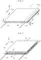
- FIG. 1 and FIG. 2 are perspective views of a thermoelectric conversion module package 1 according to one embodiment of the present invention.
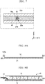
- FIG. 3 is a cross-sectional view of the thermoelectric conversion module package 1 taken along the line A-A' in FIG. 1 .
- FIG. 4 is a cross-sectional view of the thermoelectric conversion module package 1 taken along line B-B' of FIG. 1 .
- thermoelectric conversion module package 1 is provided with a thermoelectric conversion module 10 and a package 20, and has a constitution in which the thermoelectric conversion module 10 is hermetically sealed by the package 20.
- the package 20 is indicated by a broken line, with the thermoelectric conversion module 10 being shown by looking through the package 20.
- thermoelectric conversion module 10 constitutes the main body of the thermoelectric conversion module package 1 and is configured to exhibit the function of the thermoelectric conversion module package 1.
- the package 20 hermetically seals the thermoelectric conversion module 10.
- thermoelectric conversion module 10 (Thermoelectric conversion module 10)
- the thermoelectric conversion module 10 of the thermoelectric conversion module package 1 is provided with a first substrate 12 that is a low temperature-side substrate, a second substrate 13 that is a high temperature-side substrate, a thermoelectric element 11, and lead wires 15.
- the first substrate 12 and the second substrate 13 are arranged to face each other.
- the thermoelectric element 11 is composed of a plurality of pairs of P-type and N-type thermoelectric elements, and is arranged between the substrate 12 and the substrate 13.
- the lead wires 15 are configured as a pair of conductive wires that are each connected to the first substrate 12.
- the substrates 12 and 13 are each formed as a rectangular flat plate parallel to the XY plane.
- the substrates 12 and 13 are formed of an insulator material having excellent heat resistance. Since the thermoelectric conversion efficiency of the thermoelectric conversion module 10 is improved as the thermal conductivities of the substrates 12 and 13 are higher, it is preferable that the substrates 12 and 13 be formed thin with a material having a high thermal conductivity.
- a material for forming the substrates 12 and 13 for example, a ceramic material such as aluminum nitride, aluminum oxide, silicon carbide, silicon nitride or the like can be used. Further, the substrates 12 and 13 may be substrates using resins as substrates, such as so-called flexible substrates.
- Electrodes 14 are formed on each of the substrates 12 and 13.
- the electrodes 14 are formed on the upper surface of the first substrate 12 in FIG. 2 (the surface in the Z-axis positive direction), and the electrodes 14 is formed on the lower surface of the second substrate 13 in FIG. 2 (the surface in the negative direction of the Z axis). Therefore, the electrodes 14 of the first substrate 12 and the electrodes 14 of the second substrate 13 face each other in the Z-axis direction.
- Each electrode 14 is formed of a conductive material and, on the substrates 12 and 13, electrically connect pairs of the thermoelectric elements 11.
- the electrodes 14 are patterned so as to connect all the thermoelectric elements 11 in series between the substrates 12 and 13.
- the electrodes 14 of the substrates 12 and 13 can be constituted using, for example, gold (Au), nickel (Ni), tin (Sn), copper (Cu), or alloys thereof.
- the substrates 12 and 13 can have a single layer structure or a multilayer structure in which a plurality of metal materials are combined.
- the method of forming the electrodes 14 on the substrates 12 and 13 is not limited to a specific method and can be appropriately selected from known methods.
- the electrodes 14 can be formed by subjecting the substrates 12 and 13 to a metal plating treatment. In the formation of the electrodes 14, multilayer plating can be used if necessary. The metal plating process can be performed at the wafer stage before being cut into the respective substrates 12 and 13.
- the substrates 12 and 13 may be DBC (Direct Bonded Copper) substrates on which the electrodes 14 made of copper are directly bonded.
- DBC Direct Bonded Copper
- thermoelectric elements 11 are composed of P-type thermoelectric elements 11 and N-type thermoelectric elements 11.
- the thermoelectric conversion module 10 of the thermoelectric conversion module package 1 has 49 pairs of thermoelectric elements 11 arranged in 10 rows in the X-axis direction and the Y-axis direction except for two corners in the Y-axis direction at which the lead wires 15 are connected. That is, between the substrates 12 and 13, 49 P-type thermoelectric elements 11 and 49 N-type thermoelectric elements 11 are alternately arranged.
- thermoelectric element 11 is formed of a thermoelectric material, that is, the P-type thermoelectric element 11 is formed of a P-type thermoelectric material and the N-type thermoelectric element 11 is formed of an N-type thermoelectric material.
- the thermoelectric material forming the thermoelectric element 11 for example, a bismuth-tellurium-based thermoelectric material exhibiting good performance at a relatively low temperature can be used.
- thermoelectric material forming the thermoelectric element 11 examples include a half-Heusler-based thermoelectric material, a silicide-based thermoelectric material, a lead-tellurium-based thermoelectric material, a silicon-germanium-based thermoelectric material, a skutterudite-based thermoelectric material, and a tetrahedrite-based thermoelectric material.
- the lead wires 15 are joined to two corners of the first substrate 12 in the Y-axis direction and led out in the Y-axis direction. That is, the lead wires 15 are connected to the electrodes 14 at the two places where the thermoelectric element 11 is not disposed on the first substrate 12. Therefore, each lead wire 15 is electrically connected to the thermoelectric element 11 adjacent in the Y-axis direction via the electrode 14.
- a known joining material such as solder, a brazing filler metal, a conductive paste or the like can be used for joining the lead wires 15 to the first substrate 12.
- thermoelectric conversion module 10 of the thermoelectric conversion module package 1 all the thermoelectric elements 11 are connected in series between the pair of lead wires 15.
- thermoelectric conversion module 10 of the thermoelectric conversion module package 1 can be variously changed in accordance with the use of the thermoelectric conversion module package 1.
- the substrates 12 and 13 may be divided into a plurality.
- the package 20 includes a first metal foil 21, a second metal foil 22, and a resin portion 23.
- the first metal foil 21 is disposed on the lower surface of the thermoelectric conversion module 10 in FIG. 3 (the surface in the Z-axis negative direction), and covers the first substrate 12 side of the thermoelectric conversion module 10.
- the second metal foil 22 is disposed on the upper surface of the thermoelectric conversion module 10 in FIG. 3 (the surface in the Z-axis positive direction), and covers the second substrate 13 side of the thermoelectric conversion module 10.
- the resin portion 23 is provided along the outer edge portion of the thermoelectric conversion module 10 and hermetically seals the first metal foil 21 and the second metal foil 22.
- a side wall portion 21a extending in the Z-axis positive direction to a position adjacent to the thermoelectric element 11 and a flange portion 21b extending from the upper end portion of the side wall portion 21a in the X axis and Y-axis positive direction are provided at the outer edge portion of the first metal foil 21.
- a side wall portion 22a extending in the Z-axis negative direction to a position adjacent to the thermoelectric element 11 and a flange portion 22b extending from the lower end portion of the side wall portion 22a in the X axis and Y-axis positive direction are provided at the outer edge portion of the second metal foil 22.
- the flange portion 21b of the first metal foil 21 and the flange portion 22b of the second metal foil 22 are opposed to each other in the Z-axis direction at an intermediate position in the Z-axis direction of the thermoelectric conversion module 10.
- the resin portion 23 is disposed between the flange portion 21b of the first metal foil 21 and the flange portion 22b of the second metal foil 22 and hermetically connects the first metal foil 21 and the second metal foil 22.
- thermoelectric conversion module package 1 by providing the side wall portion 22a in the second metal foil 22, it is possible to dispose the resin portion 23 away from the second substrate 13 in the negative Z-axis direction. This makes it difficult for the heat of the second substrate 13 to be applied to the resin portion 23 during use of the thermoelectric conversion module package 1, so that the resin portion 23 is less likely to be damaged. Therefore, in the thermoelectric conversion module package 1, high durability and reliability are obtained.
- thermoelectric conversion module package 1 by providing the flange portions 21b, 22b, it is possible to ensure a wide bonding area of the metal foils 21, 22 with the resin portion 23. As a result, the metal foils 21, 22 are better connected via the resin portion 23, so that the durability and reliability of the thermoelectric conversion module package 1 are improved.
- the dimension L (see FIG. 3 ) of the flange portions 21b, 22b in the X-axis direction and the Y-axis direction is preferably large to some extent. Specifically, it is preferably 2 mm or more, and more preferably 3 mm or more.
- the resin portion 23 is provided with an insertion portion 23a for drawing out the lead wires 15 of the thermoelectric conversion module 10 to the outside of the package 20.
- Each lead wire 15 is drawn out from the first substrate 12 to the height of the insertion portion 23a, and hermetically passed through the resin portion 23 at the insertion portion 23a.
- the thermoelectric conversion module package 1 it is possible to expose only the lead wires 15 of the thermoelectric conversion module 10 to the outside of the package 20.
- sealing of the metal foils 21 and 22 and drawing out of the lead wires 15 can be performed collectively in the resin portion 23. Thereby, the manufacturing cost of the thermoelectric conversion module package 1 can be reduced.
- FIG. 5 is a cross-sectional view of the thermoelectric conversion module package 1 taken along line C-C' of FIG. 1 , showing a cross section of the flange portions 21b and 22b and the resin portion 23.
- FIG. 6 is an enlarged partial cross-sectional view showing the region indicated by the long-dashed short-dashed line in FIG. 5 , particularly showing an enlargement of the cross section of the insertion portion 23a.
- the entire circumference of the lead wire 15 is covered with the resin portion 23 at the insertion portion 23a, and the resin portion 23 separates the metal foils 21 and 22 from the flange portions 21b and 22b. Therefore, in the thermoelectric conversion module package 1, it is possible to prevent a short circuit caused by the lead wires 15 contacting the metal foils 21 and 22.
- FIG. 7 is a partial cross-sectional view of a thermoelectric conversion module package 1 showing a modification of the configuration shown in FIG. 6 .
- Each lead wire 15 may be provided with a covering portion 15a made of resin that hermetically covers the outer surface of the lead wire 15.
- the lead wire 15 is separated from the flange portions 21b and 22b of the metal foils 21 and 22 by the covering portion 15a.
- the covering portion 15a As a result, it is possible to more effectively prevent a short circuit caused by the lead wires 15 contacting the metal foils 21 and 22.
- the covering portion 15a is not limited to a specific configuration provided it has insulation properties and can hermetically cover the lead wires 15.
- a sealant film capable of being brought into close contact with the lead wires 15 by a heat sealer can be used as the coating portion 15a.
- the material of the sealant film may be any material as long as it can adhere well to the resin portion 23 and may be the same as the resin portion 23 or different from the resin portion 23.
- the resin portion 23 functions to suppress heat transfer between the metal foils 21 and 22, in addition to the functions of sealing the package 20 and drawing out the lead wires 15. That is, the resin portion 23 has a very low thermal conductivity compared with metal, and therefore can function to thermally insulate the metal foils 21 and 22. As a result, since the temperature difference between the first substrate 12, which is the low temperature-side substrate, and the second substrate 13, which is the high temperature-side substrate, is maintained in the thermoelectric conversion module 10, the cooling performance and the power generation performance of the thermoelectric conversion module package 1 are not impaired.
- the thickness T of the resin portion 23 in the Z-axis direction is preferably large in view of the thermal insulation of the metal foils 21 and 22 and the electrical insulation between the lead wires 15 and the metal foils 21 and 22.
- the thickness T of the resin portion 23 is too large, the heat applied from the second metal foil 22 to the resin portion 23 easily accumulates, leading to damage of the resin portion 23 easily occurring.
- the thickness T of the resin portion 23 is preferably 10 ⁇ m or more and 160 ⁇ m or less.
- the resin material forming the resin portion 23 preferably has heat resistance.
- a resin material include a polyolefin-based resin, an epoxy-based resin, a polyimide-based resin, a silicone-based resin, a phenol-based resin, a urethane-based resin, an acrylic-based resin, and the like.
- a polyolefin-based resin, an epoxy-based resin, a polyimide-based resin, a silicone-based resin and a phenol-based resin are preferable, and from the viewpoint of adhesion to the metal foils, a polyolefin-based resin, an epoxy-based resin, and a silicone-based resin are more preferable.
- Examples of a polyolefin-based resin include low-density, medium-density or high-density polyethylene; an ethylene-a olefin copolymer; homo, block or random polypropylene; a propylene-a olefin copolymer and the like. From the viewpoint of heat resistance, homo, block or random polypropylene is preferable. Further, from the viewpoint of adhesion to the metal foils, the polyolefin-based resin may be graft-modified with an acid such as maleic anhydride.
- the epoxy-based resin is composed of a thermosetting composition containing at least an epoxy resin and a curing agent, and may contain a thermoplastic resin from the viewpoint of imparting flexibility or may contain an inorganic filler from the viewpoint of improving heat resistance.
- the epoxy resin is not particularly limited provided it is one having two or more epoxy groups in one molecule, with examples thereof including bisphenol F, bisphenol A, bisphenol S, resorcinol, dihydroxynaphthalene, dicyclopentadiene diphenol, dicyclopentadiene dixylenol and other diglycidyl ethers, epoxidized phenol novolac, epoxidized cresol novolac, epoxidized trisphenylolmethane, epoxidized tetraphenylolethane, epoxidized metaxylenediamine, cyclohexane epoxide and other alicyclic epoxies, and phenoxy resin.
- the curing agent examples include a phenol resin, a melamine resin, a maleimide resin, a xylene resin, a furan resin, a cyanate ester resin, and an aromatic polyamine.
- an addition-curable type there are an addition-curable type, a condensation-curable type, and a UV-curable type, with an addition-curable type that is curable in a short time by heating being preferable.
- An addition-curable silicone resin is a compound having a reactive functional group such as an alkenyl group, with the alkenyl group being one that causes crosslinking with a curing agent such as organic peroxide and addition reaction with hydrogen siloxane, and cured by mixed curing or heat curing. Further, it may contain a catalyst such as platinum for promoting curing, and an adhesion imparting agent such as a coupling agent for improving adhesion to the metal foils.
- the resin material forming the resin portion 23 may be another resin material provided it is one capable of obtaining high adhesiveness to the metal foils 21 and 22.
- the resin portion 23 may be constituted with a single resin material or may be constituted with a plurality of kinds of resin materials. Further, the resin material forming the resin portion 23 may be a sheet shape or a flow shape having viscosity.
- the thermoelectric conversion module package 1 includes heat transfer layers 31 and 32.
- the first heat transfer layer 31 is provided between the first substrate 12 and the first metal foil 21 and is in close contact with the first substrate 12 and the first metal foil 21.
- the second heat transfer layer 32 is provided between the second substrate 13 and the second metal foil 22 and is in close contact with the second substrate 13 and the second metal foil 22.
- the heat transfer layers 31 and 32 improve the heat transfer between the substrates 12 and 13 and the metal foils 21 and 22 by reducing the thermal resistance between the substrates 12 and 13 and the metal foils 21 and 22, respectively.
- heat transfer layers 31 and 32 for example, silicon grease, a graphite sheet, or a thermally conductive adhesive can be used.
- the members used for the heat transfer layers 31 and 32 may be the same or different.
- the combination of members used for the heat transfer layers 31 and 32 can be determined as appropriate.
- silicon grease can be used for the first heat transfer layer 31 on the first substrate 12 side, which is the low-temperature side substrate
- a graphite sheet with high heat resistance can be used for the second heat transfer layer 32 on the second substrate 13 side, which is the high-temperature side substrate.
- thermoelectric conversion module package 1 it is possible to favorably perform thermoelectric conversion between the potential difference between the pair of lead wires 15 drawn to the outside of the package 20 and the temperature difference between the metal foils 21, 22.
- thermoelectric conversion module package 1 since the thermoelectric conversion module 10 is hermetically sealed by the package 20, even when used in an environment where corrosion is likely to occur in the thermoelectric element 11, corrosion does not occur in the thermoelectric element 11. Moreover, in the thermoelectric conversion module package 1, the performance of the thermoelectric conversion module 10 is not affected by humidity even when used in a high humidity environment. Therefore, high durability and reliability are obtained in the thermoelectric conversion module package 1.
- the space in the package 20 be a non-oxidizing atmosphere having a smaller amount of oxygen than the atmosphere. This makes it possible to prevent an increase in electrical resistance of the thermoelectric conversion module package 1 due to oxidation of the thermoelectric element 11. Accordingly, the thermoelectric conversion module package 1 can obtain even higher durability and reliability. More specifically, the space within the package 20 can be made a non-oxidizing atmosphere by enclosing an inert gas such as nitrogen or argon, for example. Further, the space in the package 20 may be depressurized.
- thermoelectric conversion module package 1 is extremely lightweight because the package 20 is composed of the lightweight metal foils 21 and 22 and the resin portion 23. This facilitates the handling of the thermoelectric conversion module package 1, so that it is possible to efficiently perform mounting of the thermoelectric conversion module package 1 to other devices and the like.
- the metal foils 21 and 22 have flexibility, it is difficult for a load to be applied to the thermoelectric conversion module 10 due to thermal expansion or thermal contraction of the metal foils 21 and 22 during use of the thermoelectric conversion module package 1. As a result, durability and reliability are further improved in the thermoelectric conversion module package 1.
- the raw material cost can be reduced.
- the thickness of the metal foils 21 and 22 is preferably 10 ⁇ m or more, and more preferably 20 ⁇ m or more.
- the metal foils 21 and 22 are also required to have flexibility for obtaining high adhesion to the heat transfer layer 32.
- the thickness of the metal foils 21 and 22 is preferably 300 ⁇ m or less, and more preferably 200 ⁇ m or less.
- Examples of materials for forming the metal foils 21 and 22 include aluminum, aluminum alloys, copper, copper alloys, and stainless steel, with aluminum and aluminum alloys having light weight and flexibility being preferable.
- the metal foils 21 and 22 may be subjected to an adhesion improving treatment such as an alumite treatment, a chemical conversion treatment, a plating treatment, a coupling treatment and the like from the viewpoint of improving the adhesiveness with the resin material of the resin portion 23.
- FIGS. 8A to 8E are cross-sectional views illustrating a method of sealing the thermoelectric conversion module 10 with the package 20. The method of sealing the thermoelectric conversion module 10 by the package 20 will be described with reference to FIGS. 8A to 8E .
- the heat transfer layer 31 is arranged on the bottom surface of the first metal foil 21 that is molded is advance by press molding or the like.
- a first resin piece 123a for forming each resin portion 23 is disposed on the flange portion 21b of the first metal foil 21.
- the thermoelectric conversion module 10 is arranged on the heat transfer layer 31.
- the lead wires 15 of the thermoelectric conversion module 10 are arranged on each first resin piece 123a.
- the heat transfer layer 32 is disposed on the second substrate 13 of the thermoelectric conversion module 10.
- the second metal foil 22 molded in advance by press molding or the like is placed on the heat transfer layer 32.
- a second resin piece 123b formed similarly to the first resin piece 123a is disposed, and each lead wire 15 is sandwiched between the resin pieces 123a, 123b.
- heat is applied to the assembly shown in FIG. 8D to weld the resin pieces 23a and 123b, whereby the resin portion 23 is formed.
- the thermoelectric conversion module package 1 shown in FIG. 8E is obtained.
- thermoelectric conversion module package 1 since the metal foils 21 and 22 are sealed by the welding of the resin pieces 123a and 123b, it is unnecessary to expose the thermoelectric conversion module 10 to a high temperature as compared with a method such as welding. Therefore, the performance and reliability of the thermoelectric conversion module package 1 are hardly deteriorated. In addition, since the heat capacities of the metal foils 21 and 22 are small and the temperature of the resin pieces 123a and 123b rises in a short time, the metal foils 21 and 22 can be sealed in a short time.
- the method for forming the resin portion 23 in the package 20 is not limited to the welding of the resin pieces 123a and 123b, and any known method can be adopted freely.
- the resin portion 23 can be formed with an adhesive.
- the adhesive is applied to the flange portions 21b and 22b of the metal foils 21 and 22, and the adhesive is cured in a state in which the lead wires 15 are passed through the adhesive between the flange portions 21b and 22b.
- FIGS. 9A and 9B are cross-sectional views of a thermoelectric conversion module package 1 showing a modification of the package 20.
- the side wall portion 21a of the first metal foil 21 is short, and the side wall portion 22a of the second metal foil 22 is long. Therefore, the flange portions 21b and 22b and the resin portion 23 are arranged at low positions in the Z-axis direction. As a result, since the resin portion 23 can be further separated from the second substrate 13 in the negative direction of the Z axis (the lower side in FIG. 9A ), the heat of the second substrate 13 is less likely to be applied to the resin portion 23. Therefore, in the thermoelectric conversion module package 1, durability and reliability can be improved.
- the first metal foil 21 of the package 20 shown in FIG. 9B is not provided with the side wall portion 21a, and instead there is provided an expansion portion 21c that expands in the X-axis and Y-axis positive directions (outward) from the region facing the first substrate 12. That is, the first metal foil 21 is formed in a flat plate shape.
- the side wall portion 22a of the second metal foil 22 is made longer. Accordingly, since the resin portion 23 can be further separated from the second substrate 13 in the negative Z-axis direction (downward), the heat of the second substrate 13 has less of a tendency to be applied to the resin portion 23. Therefore, in the thermoelectric conversion module package 1, durability and reliability can be further improved.
- thermoelectric conversion module 10 Modification of thermoelectric conversion module 10.
- FIG. 10 is a cross-sectional view of the thermoelectric conversion module package 1 having an assembly of the thermoelectric conversion module 10 including a plurality of the thermoelectric conversion modules 10.
- the thermoelectric conversion module package 1 has an assembly of four thermoelectric conversion modules 10. Further, the thermoelectric conversion module package 1 has connecting portions 16 for connecting the four thermoelectric conversion modules 10 in series. Each connecting portion 16 is formed of, for example, a conductive wire or a metal foil.
- the lead wires 15 are respectively drawn out from the thermoelectric conversion modules 10 at both ends of the series connection in the four thermoelectric conversion modules 10.
- thermoelectric conversion module package 1 by combining a plurality of the thermoelectric conversion modules 10, it is possible to increase the area without increasing the size of each thermoelectric conversion module 10.
- thermoelectric conversion module package 1 since the thermal stress is mitigated more favorably by the configuration divided into a plurality of thermoelectric conversion modules 10 than the configuration in which the thermoelectric conversion module 10 itself is enlarged, excellent durability and reliability are obtained.
- FIG. 11 is a cross-sectional view of the thermoelectric conversion module package 1 taken along line D-D' in FIG. 10 , and shows the area between the two thermoelectric conversion modules 10.
- the metal foils 21 and 22 are not held in the region between the two thermoelectric conversion modules 10. Therefore, concave portions 21r and 22r recessed inward in the Z-axis direction may be generated in the metal foils 21 and 22.
- the concave portions 21r and 22r of the metal foils 21 and 22 are particularly likely to occur in the configuration in which the space inside the package 20 is depressurized. When the concave portions 21r and 22r make contact with the connecting portion 16, a short circuit occurs due to conduction between the connecting portions 16.
- thermoelectric conversion module package 1 is provided with two resin sheets 17 sandwiching the connecting portion 16 in the Z-axis direction. Thereby, it is possible to prevent the recessed portions 21r and 22r of the metal foils 21 and 22 from contacting the connecting portions 16. Note that in the case of using a covered wire or the like which is insulated in advance as the connecting portion 16, it is not necessary to provide the resin sheet 17.
- the lead wire 15 provided with the covering portion 15a such as a sealant film shown in FIG. 7 may be used as the connecting portion 16. In this case as well, there is no need to provide the resin sheet 17.
- thermoelectric conversion module packages of the embodiments and comparative example are shown below.
- Thermoelectric conversion module A-1 The size of the first substrate 12 is set to be 40 mm in width (X-axis direction), 32 mm in length (Y-axis direction), 2 mm in height (Z-axis direction), and the size of the second substrate 13 is set to be 40 mm in width (X-axis direction), 35 mm in length (Y-axis direction), and 2 mm in height (Z-axis direction).
- the thermoelectric element 11 is formed with a bismuth telluride-based thermoelectric material.
- Thermoelectric conversion module A-2 The size of the first substrate 12 is set to be 40 mm in width (X-axis direction), 38 mm in length (Y-axis direction), 2 mm in height (Z-axis direction), and the size of the second substrate 13 is set to be 40 mm in width (X-axis direction), 35 mm in length (Y-axis direction) of 40 mm, and 2 mm in height (Z-axis direction).
- the thermoelectric element 11 was formed with a bismuth telluride-based thermoelectric material.
- thermoelectric conversion module 10 In the thermoelectric conversion module packages of the embodiments and the comparative example, the thermoelectric conversion module 10, the heat transfer layer 31, the heat transfer layer 32, the first metal foil 21, the second metal foil 22 and the resin portion 23 were constituted using the materials of Table 1.
- Table 1 Embodiments & Comparative Example Thermoelectric Conversion Module 10 Heat Transfer Layer 31 Heat Transfer Layer 32 First Metal Foil 21 Second Metal Foil 22 Resin Portion 23 Embodiment 1 A-1 B-1 B-2 C-1 C-1 D-1 Embodiment 2 A-2 B-1 B-2 C-2 C-2 D-1 Embodiment 3 A-1 B-2 B-2 C-3 C-3 D-1 Embodiment 4 A-1 B-1 B-2 C-3 C-3 D-1 Embodiment 5 A-1 B-1 B-2 C-4 C-4 D-1 Embodiment 6 A-1 B-1 B-2 C-5 C-5 D-1 Embodiment 7 A-1 B-1 B-2 C-6 C-6 D-1 Embodiment 8 A-1 B-1 B-2 C-7 C-7 D-1 Embodiment 9 A-1 B-1 B
- thermoelectric conversion module packages of the embodiments and the comparative example were evaluated according to the following method.
- Durability tests were conducted on the thermoelectric conversion module packages of the embodiments and the comparative example.
- the durability test while keeping the temperature of the first metal foil 21 on the first substrate 12 at 90° C, the temperature of the second metal foil 22 on the second substrate 13 was changed in the range of 90°C to 330°C. More specifically, a cycle was performed 1,000 times in which the temperature of the second metal foil 22 on the second substrate 13 was raised from 90°C to 330°C in 5 minutes, held at 330°C for 2 minutes, cooled from 330°C to 90°C in 5 minutes, and held at 90°C for 2 minutes.
- thermoelectric conversion module package excellent in durability could be provided.
- thermoelectric conversion module 10 of the thermoelectric conversion module package 1 has only one thermoelectric element layer.
- thermoelectric conversion module package 1 may have an assembly of the thermoelectric conversion module 10 including a plurality of thermoelectric conversion modules 10 stacked in the Z-axis direction.
Description
- The present invention relates to a thermoelectric conversion module package in which a thermoelectric conversion module is sealed with a package.
- A thermoelectric conversion module can be used as a cooling module utilizing the Peltier effect of a thermoelectric material or as a power generation module utilizing the Seebeck effect of a thermoelectric material. With the expansion of applications of thermoelectric conversion modules, thermoelectric conversion modules have come to be used in various environments. In a thermoelectric conversion module, performance deteriorates due to oxidation and corrosion of the thermoelectric material.
-
JP 2006-49872 A -
US 3 225 549 A is related to the preamble ofclaim 1, andJP 2000 188430 A - In the thermoelectric conversion module according to
JP 2006-49872 A - Further, in the thermoelectric conversion module according to
JP 2006-49872 A - In view of the circumstances described above, an object of the present invention is to provide a configuration capable of easily sealing a thermoelectric conversion module with a package without impairing the performance thereof. Means for Solving the Problems
- To achieve the object, a thermoelectric conversion module package according to one embodiment of the present invention is provided with a thermoelectric conversion module and a package.
- The thermoelectric conversion module includes a first and a second substrate opposed to each other, a plurality of thermoelectric elements arranged between the first and second substrates, and a first and a second lead wire drawn out from one of the first and second substrates.
- The package includes a first metal foil covering the first substrate on one side of the thermoelectric conversion module, a second metal foil covering the second substrate on the other side of the thermoelectric conversion module, a resin portion hermetically connecting the first metal foil and the second metal foil along an outer edge portion of the thermoelectric conversion module, and an insertion portion for hermetically passing the first and second lead wires through the resin portion.
- The second metal foil has a side wall portion extending toward the first metal foil at the outer edge portion of the thermoelectric conversion module, and a flange portion protruding outward from the side wall portion.
- The resin portion connects the first metal foil and the flange portion.
- The resin portion may be disposed at a position closer to the first substrate than the second substrate.
- The first metal foil may have an expansion portion that is expanded outward from a region facing the first substrate.
- The resin portion may connect the expansion portion and the flange portion.
- The thermoelectric conversion module may be configured as an assembly including a plurality of the thermoelectric conversion modules.
- A connecting portion for electrically connecting the plurality of thermoelectric conversion modules may be further provided.
-
-
FIG. 1 is a perspective view showing a thermoelectric conversion module package according to one embodiment of the present invention. -
FIG. 2 is a perspective view showing the thermoelectric conversion module package, looking through the package. -
FIG. 3 is a cross-sectional view of the thermoelectric conversion module package taken along line A-A' inFIG. 1 . -
FIG. 4 is a cross-sectional view of the thermoelectric conversion module package taken along line B-B' inFIG. 1 . -
FIG. 5 is a cross-sectional view of the thermoelectric conversion module package taken along line C-C' inFIG. 1 . -
FIG. 6 is an enlarged cross-sectional view showing the configuration of the area surrounded by the long-dashed short-dashed line inFIG. 5 of the thermoelectric conversion module package. -
FIG. 7 is an enlarged cross-sectional view showing a modification of the configuration shown inFIG. 6 in the thermoelectric conversion module package. -
FIG. 8A is a cross-sectional view showing a first step in sealing the thermoelectric conversion module with the package in the thermoelectric conversion module package. -
FIG. 8B is a cross-sectional view showing a second step in sealing the thermoelectric conversion module with the package in the thermoelectric conversion module package. -
FIG. 8C is a cross-sectional view showing a third step in sealing the thermoelectric conversion module with the package in the thermoelectric conversion module package. -
FIG. 8D is a cross-sectional view showing a fourth step in sealing the thermoelectric conversion module with the package in the thermoelectric conversion module package. -
FIG. 8E is a cross-sectional view showing a fifth step in sealing the thermoelectric conversion module with the package in the thermoelectric conversion module package. -
FIG. 9A is a cross-sectional view showing a modification of the package in the thermoelectric conversion module package. -
FIG. 9B is a cross-sectional view showing another modification of the package in the thermoelectric conversion module package. -
FIG. 10 is a plan view showing a modification of the thermoelectric conversion module in the thermoelectric conversion module package. -
FIG. 11 is a partial cross-sectional view of the thermoelectric conversion module package along line D-D' inFIG. 10 . - Hereinbelow, an embodiment of the present invention will be described with reference to the drawings.
- In the drawings, mutually orthogonal X-, Y-, and Z-axes are shown as appropriate. The X axis, the Y axis, and the Z axis are common to all the drawings. In each axis, the direction indicated by the arrow is called the positive direction, while the direction opposite to the direction indicated by the arrow is called the negative direction.
-
FIG. 1 and FIG. 2 are perspective views of a thermoelectricconversion module package 1 according to one embodiment of the present invention.FIG. 3 is a cross-sectional view of the thermoelectricconversion module package 1 taken along the line A-A' inFIG. 1 .FIG. 4 is a cross-sectional view of the thermoelectricconversion module package 1 taken along line B-B' ofFIG. 1 . - The thermoelectric
conversion module package 1 is provided with athermoelectric conversion module 10 and apackage 20, and has a constitution in which thethermoelectric conversion module 10 is hermetically sealed by thepackage 20. InFIG. 2 , thepackage 20 is indicated by a broken line, with thethermoelectric conversion module 10 being shown by looking through thepackage 20. - The
thermoelectric conversion module 10 constitutes the main body of the thermoelectricconversion module package 1 and is configured to exhibit the function of the thermoelectricconversion module package 1. Thepackage 20 hermetically seals thethermoelectric conversion module 10. - The
thermoelectric conversion module 10 of the thermoelectricconversion module package 1 is provided with afirst substrate 12 that is a low temperature-side substrate, asecond substrate 13 that is a high temperature-side substrate, athermoelectric element 11, and leadwires 15. Thefirst substrate 12 and thesecond substrate 13 are arranged to face each other. Thethermoelectric element 11 is composed of a plurality of pairs of P-type and N-type thermoelectric elements, and is arranged between thesubstrate 12 and thesubstrate 13. Thelead wires 15 are configured as a pair of conductive wires that are each connected to thefirst substrate 12. - The
substrates substrates thermoelectric conversion module 10 is improved as the thermal conductivities of thesubstrates substrates substrates substrates -
Electrodes 14 are formed on each of thesubstrates electrodes 14 are formed on the upper surface of thefirst substrate 12 inFIG. 2 (the surface in the Z-axis positive direction), and theelectrodes 14 is formed on the lower surface of thesecond substrate 13 inFIG. 2 (the surface in the negative direction of the Z axis). Therefore, theelectrodes 14 of thefirst substrate 12 and theelectrodes 14 of thesecond substrate 13 face each other in the Z-axis direction. Eachelectrode 14 is formed of a conductive material and, on thesubstrates thermoelectric elements 11. Theelectrodes 14 are patterned so as to connect all thethermoelectric elements 11 in series between thesubstrates - The
electrodes 14 of thesubstrates substrates - The method of forming the
electrodes 14 on thesubstrates - As an example, the
electrodes 14 can be formed by subjecting thesubstrates electrodes 14, multilayer plating can be used if necessary. The metal plating process can be performed at the wafer stage before being cut into therespective substrates - Furthermore, the
substrates electrodes 14 made of copper are directly bonded. - The
thermoelectric elements 11 are composed of P-typethermoelectric elements 11 and N-typethermoelectric elements 11. Thethermoelectric conversion module 10 of the thermoelectricconversion module package 1 has 49 pairs ofthermoelectric elements 11 arranged in 10 rows in the X-axis direction and the Y-axis direction except for two corners in the Y-axis direction at which thelead wires 15 are connected. That is, between thesubstrates thermoelectric elements 11 and 49 N-typethermoelectric elements 11 are alternately arranged. - The
thermoelectric element 11 is formed of a thermoelectric material, that is, the P-typethermoelectric element 11 is formed of a P-type thermoelectric material and the N-typethermoelectric element 11 is formed of an N-type thermoelectric material. As the thermoelectric material forming thethermoelectric element 11, for example, a bismuth-tellurium-based thermoelectric material exhibiting good performance at a relatively low temperature can be used. Examples of the thermoelectric material forming thethermoelectric element 11 that can be adopted include a half-Heusler-based thermoelectric material, a silicide-based thermoelectric material, a lead-tellurium-based thermoelectric material, a silicon-germanium-based thermoelectric material, a skutterudite-based thermoelectric material, and a tetrahedrite-based thermoelectric material. - The
lead wires 15 are joined to two corners of thefirst substrate 12 in the Y-axis direction and led out in the Y-axis direction. That is, thelead wires 15 are connected to theelectrodes 14 at the two places where thethermoelectric element 11 is not disposed on thefirst substrate 12. Therefore, eachlead wire 15 is electrically connected to thethermoelectric element 11 adjacent in the Y-axis direction via theelectrode 14. For example, a known joining material such as solder, a brazing filler metal, a conductive paste or the like can be used for joining thelead wires 15 to thefirst substrate 12. - With the above configuration, in the
thermoelectric conversion module 10 of the thermoelectricconversion module package 1, all thethermoelectric elements 11 are connected in series between the pair oflead wires 15. - It is a matter of course that the configuration of the
thermoelectric conversion module 10 of the thermoelectricconversion module package 1 described above can be variously changed in accordance with the use of the thermoelectricconversion module package 1. For example, it is possible to appropriately change the number and arrangement of thethermoelectric elements 11, the shapes of thesubstrates substrates - The
package 20 includes afirst metal foil 21, asecond metal foil 22, and aresin portion 23. Thefirst metal foil 21 is disposed on the lower surface of thethermoelectric conversion module 10 inFIG. 3 (the surface in the Z-axis negative direction), and covers thefirst substrate 12 side of thethermoelectric conversion module 10. Thesecond metal foil 22 is disposed on the upper surface of thethermoelectric conversion module 10 inFIG. 3 (the surface in the Z-axis positive direction), and covers thesecond substrate 13 side of thethermoelectric conversion module 10. Theresin portion 23 is provided along the outer edge portion of thethermoelectric conversion module 10 and hermetically seals thefirst metal foil 21 and thesecond metal foil 22. - A
side wall portion 21a extending in the Z-axis positive direction to a position adjacent to thethermoelectric element 11 and aflange portion 21b extending from the upper end portion of theside wall portion 21a in the X axis and Y-axis positive direction are provided at the outer edge portion of thefirst metal foil 21. Aside wall portion 22a extending in the Z-axis negative direction to a position adjacent to thethermoelectric element 11 and aflange portion 22b extending from the lower end portion of theside wall portion 22a in the X axis and Y-axis positive direction are provided at the outer edge portion of thesecond metal foil 22. - With such a configuration, the
flange portion 21b of thefirst metal foil 21 and theflange portion 22b of thesecond metal foil 22 are opposed to each other in the Z-axis direction at an intermediate position in the Z-axis direction of thethermoelectric conversion module 10. Theresin portion 23 is disposed between theflange portion 21b of thefirst metal foil 21 and theflange portion 22b of thesecond metal foil 22 and hermetically connects thefirst metal foil 21 and thesecond metal foil 22. - In the thermoelectric
conversion module package 1, by providing theside wall portion 22a in thesecond metal foil 22, it is possible to dispose theresin portion 23 away from thesecond substrate 13 in the negative Z-axis direction. This makes it difficult for the heat of thesecond substrate 13 to be applied to theresin portion 23 during use of the thermoelectricconversion module package 1, so that theresin portion 23 is less likely to be damaged. Therefore, in the thermoelectricconversion module package 1, high durability and reliability are obtained. - In addition, in the
package 20, by providing theflange portions resin portion 23. As a result, the metal foils 21, 22 are better connected via theresin portion 23, so that the durability and reliability of the thermoelectricconversion module package 1 are improved. - From such a viewpoint, the dimension L (see
FIG. 3 ) of theflange portions - As shown in
FIG. 4 , theresin portion 23 is provided with aninsertion portion 23a for drawing out thelead wires 15 of thethermoelectric conversion module 10 to the outside of thepackage 20. Eachlead wire 15 is drawn out from thefirst substrate 12 to the height of theinsertion portion 23a, and hermetically passed through theresin portion 23 at theinsertion portion 23a. As a result, in the thermoelectricconversion module package 1, it is possible to expose only thelead wires 15 of thethermoelectric conversion module 10 to the outside of thepackage 20. As described above, in thepackage 20, sealing of the metal foils 21 and 22 and drawing out of thelead wires 15 can be performed collectively in theresin portion 23. Thereby, the manufacturing cost of the thermoelectricconversion module package 1 can be reduced. -
FIG. 5 is a cross-sectional view of the thermoelectricconversion module package 1 taken along line C-C' ofFIG. 1 , showing a cross section of theflange portions resin portion 23.FIG. 6 is an enlarged partial cross-sectional view showing the region indicated by the long-dashed short-dashed line inFIG. 5 , particularly showing an enlargement of the cross section of theinsertion portion 23a. As shown inFIG. 6 , the entire circumference of thelead wire 15 is covered with theresin portion 23 at theinsertion portion 23a, and theresin portion 23 separates the metal foils 21 and 22 from theflange portions conversion module package 1, it is possible to prevent a short circuit caused by thelead wires 15 contacting the metal foils 21 and 22. -
FIG. 7 is a partial cross-sectional view of a thermoelectricconversion module package 1 showing a modification of the configuration shown inFIG. 6 . Eachlead wire 15 may be provided with a coveringportion 15a made of resin that hermetically covers the outer surface of thelead wire 15. As a result, even when a positional deviation occurs in the Z-axis direction (vertical direction) of thelead wire 15, thelead wire 15 is separated from theflange portions portion 15a. As a result, it is possible to more effectively prevent a short circuit caused by thelead wires 15 contacting the metal foils 21 and 22. - The covering
portion 15a is not limited to a specific configuration provided it has insulation properties and can hermetically cover thelead wires 15. For example, as thecoating portion 15a, a sealant film capable of being brought into close contact with thelead wires 15 by a heat sealer can be used. The material of the sealant film may be any material as long as it can adhere well to theresin portion 23 and may be the same as theresin portion 23 or different from theresin portion 23. - In the thermoelectric
conversion module package 1, theresin portion 23 functions to suppress heat transfer between the metal foils 21 and 22, in addition to the functions of sealing thepackage 20 and drawing out thelead wires 15. That is, theresin portion 23 has a very low thermal conductivity compared with metal, and therefore can function to thermally insulate the metal foils 21 and 22. As a result, since the temperature difference between thefirst substrate 12, which is the low temperature-side substrate, and thesecond substrate 13, which is the high temperature-side substrate, is maintained in thethermoelectric conversion module 10, the cooling performance and the power generation performance of the thermoelectricconversion module package 1 are not impaired. - The thickness T of the
resin portion 23 in the Z-axis direction (seeFIG. 3 ) is preferably large in view of the thermal insulation of the metal foils 21 and 22 and the electrical insulation between thelead wires 15 and the metal foils 21 and 22. On the other hand, if the thickness T of theresin portion 23 is too large, the heat applied from thesecond metal foil 22 to theresin portion 23 easily accumulates, leading to damage of theresin portion 23 easily occurring. - From this viewpoint, the thickness T of the
resin portion 23 is preferably 10 µm or more and 160 µm or less. - The resin material forming the
resin portion 23 preferably has heat resistance. Examples of such a resin material include a polyolefin-based resin, an epoxy-based resin, a polyimide-based resin, a silicone-based resin, a phenol-based resin, a urethane-based resin, an acrylic-based resin, and the like. From the viewpoint of heat resistance, a polyolefin-based resin, an epoxy-based resin, a polyimide-based resin, a silicone-based resin and a phenol-based resin are preferable, and from the viewpoint of adhesion to the metal foils, a polyolefin-based resin, an epoxy-based resin, and a silicone-based resin are more preferable. - Examples of a polyolefin-based resin include low-density, medium-density or high-density polyethylene; an ethylene-a olefin copolymer; homo, block or random polypropylene; a propylene-a olefin copolymer and the like. From the viewpoint of heat resistance, homo, block or random polypropylene is preferable. Further, from the viewpoint of adhesion to the metal foils, the polyolefin-based resin may be graft-modified with an acid such as maleic anhydride.
- The epoxy-based resin is composed of a thermosetting composition containing at least an epoxy resin and a curing agent, and may contain a thermoplastic resin from the viewpoint of imparting flexibility or may contain an inorganic filler from the viewpoint of improving heat resistance.
- The epoxy resin is not particularly limited provided it is one having two or more epoxy groups in one molecule, with examples thereof including bisphenol F, bisphenol A, bisphenol S, resorcinol, dihydroxynaphthalene, dicyclopentadiene diphenol, dicyclopentadiene dixylenol and other diglycidyl ethers, epoxidized phenol novolac, epoxidized cresol novolac, epoxidized trisphenylolmethane, epoxidized tetraphenylolethane, epoxidized metaxylenediamine, cyclohexane epoxide and other alicyclic epoxies, and phenoxy resin.
- Examples of the curing agent include a phenol resin, a melamine resin, a maleimide resin, a xylene resin, a furan resin, a cyanate ester resin, and an aromatic polyamine.
- As the silicone-based resin, there are an addition-curable type, a condensation-curable type, and a UV-curable type, with an addition-curable type that is curable in a short time by heating being preferable. An addition-curable silicone resin is a compound having a reactive functional group such as an alkenyl group, with the alkenyl group being one that causes crosslinking with a curing agent such as organic peroxide and addition reaction with hydrogen siloxane, and cured by mixed curing or heat curing. Further, it may contain a catalyst such as platinum for promoting curing, and an adhesion imparting agent such as a coupling agent for improving adhesion to the metal foils.
- The resin material forming the
resin portion 23 may be another resin material provided it is one capable of obtaining high adhesiveness to the metal foils 21 and 22. Theresin portion 23 may be constituted with a single resin material or may be constituted with a plurality of kinds of resin materials. Further, the resin material forming theresin portion 23 may be a sheet shape or a flow shape having viscosity. - As shown in
FIGS. 3 and 4 , the thermoelectricconversion module package 1 includes heat transfer layers 31 and 32. The firstheat transfer layer 31 is provided between thefirst substrate 12 and thefirst metal foil 21 and is in close contact with thefirst substrate 12 and thefirst metal foil 21. The secondheat transfer layer 32 is provided between thesecond substrate 13 and thesecond metal foil 22 and is in close contact with thesecond substrate 13 and thesecond metal foil 22. The heat transfer layers 31 and 32 improve the heat transfer between thesubstrates substrates - As the heat transfer layers 31 and 32, for example, silicon grease, a graphite sheet, or a thermally conductive adhesive can be used. The members used for the heat transfer layers 31 and 32 may be the same or different. The combination of members used for the heat transfer layers 31 and 32 can be determined as appropriate. For example, silicon grease can be used for the first
heat transfer layer 31 on thefirst substrate 12 side, which is the low-temperature side substrate, and a graphite sheet with high heat resistance can be used for the secondheat transfer layer 32 on thesecond substrate 13 side, which is the high-temperature side substrate. - With the above configuration, in the thermoelectric
conversion module package 1, it is possible to favorably perform thermoelectric conversion between the potential difference between the pair oflead wires 15 drawn to the outside of thepackage 20 and the temperature difference between the metal foils 21, 22. - In the thermoelectric
conversion module package 1, since thethermoelectric conversion module 10 is hermetically sealed by thepackage 20, even when used in an environment where corrosion is likely to occur in thethermoelectric element 11, corrosion does not occur in thethermoelectric element 11. Moreover, in the thermoelectricconversion module package 1, the performance of thethermoelectric conversion module 10 is not affected by humidity even when used in a high humidity environment. Therefore, high durability and reliability are obtained in the thermoelectricconversion module package 1. - In the thermoelectric
conversion module package 1, it is preferable that the space in thepackage 20 be a non-oxidizing atmosphere having a smaller amount of oxygen than the atmosphere. This makes it possible to prevent an increase in electrical resistance of the thermoelectricconversion module package 1 due to oxidation of thethermoelectric element 11. Accordingly, the thermoelectricconversion module package 1 can obtain even higher durability and reliability. More specifically, the space within thepackage 20 can be made a non-oxidizing atmosphere by enclosing an inert gas such as nitrogen or argon, for example. Further, the space in thepackage 20 may be depressurized. - Furthermore, the thermoelectric
conversion module package 1 is extremely lightweight because thepackage 20 is composed of the lightweight metal foils 21 and 22 and theresin portion 23. This facilitates the handling of the thermoelectricconversion module package 1, so that it is possible to efficiently perform mounting of the thermoelectricconversion module package 1 to other devices and the like. In addition, since the metal foils 21 and 22 have flexibility, it is difficult for a load to be applied to thethermoelectric conversion module 10 due to thermal expansion or thermal contraction of the metal foils 21 and 22 during use of the thermoelectricconversion module package 1. As a result, durability and reliability are further improved in the thermoelectricconversion module package 1. In addition, by using the metal foils 21 and 22 for thepackage 20, the raw material cost can be reduced. - Since strength is required of the metal foils 21 and 22 to serve as the housing of the thermoelectric
conversion module package 1, it is preferable not to make the metal foils 21 and 22 too thin. If the metal foils 21 and 22 are made too thin, discontinuous portions such as pinholes are generated in the metal foils 21 and 22, and the airtightness inside thepackage 20 may be impaired in some cases. From this viewpoint, the thickness of the metal foils 21 and 22 is preferably 10 µm or more, and more preferably 20 µm or more. - On the other hand, the metal foils 21 and 22 are also required to have flexibility for obtaining high adhesion to the
heat transfer layer 32. From this viewpoint, the thickness of the metal foils 21 and 22 is preferably 300 µm or less, and more preferably 200 µm or less. - Examples of materials for forming the metal foils 21 and 22 include aluminum, aluminum alloys, copper, copper alloys, and stainless steel, with aluminum and aluminum alloys having light weight and flexibility being preferable. The metal foils 21 and 22 may be subjected to an adhesion improving treatment such as an alumite treatment, a chemical conversion treatment, a plating treatment, a coupling treatment and the like from the viewpoint of improving the adhesiveness with the resin material of the
resin portion 23. -
FIGS. 8A to 8E are cross-sectional views illustrating a method of sealing thethermoelectric conversion module 10 with thepackage 20. The method of sealing thethermoelectric conversion module 10 by thepackage 20 will be described with reference toFIGS. 8A to 8E . - As shown in
FIG. 8A , theheat transfer layer 31 is arranged on the bottom surface of thefirst metal foil 21 that is molded is advance by press molding or the like. Afirst resin piece 123a for forming eachresin portion 23 is disposed on theflange portion 21b of thefirst metal foil 21. Next, as shown inFIG. 8B , thethermoelectric conversion module 10 is arranged on theheat transfer layer 31. At this time, thelead wires 15 of thethermoelectric conversion module 10 are arranged on eachfirst resin piece 123a. Subsequently, as shown inFIG. 8C , theheat transfer layer 32 is disposed on thesecond substrate 13 of thethermoelectric conversion module 10. - Thereafter, as shown in
FIG. 8D , thesecond metal foil 22 molded in advance by press molding or the like is placed on theheat transfer layer 32. On theflange portion 22b of thesecond metal foil 22, asecond resin piece 123b formed similarly to thefirst resin piece 123a is disposed, and eachlead wire 15 is sandwiched between theresin pieces FIG. 8D to weld theresin pieces resin portion 23 is formed. Thereby, the thermoelectricconversion module package 1 shown inFIG. 8E is obtained. - In this method, since the metal foils 21 and 22 are sealed by the welding of the
resin pieces thermoelectric conversion module 10 to a high temperature as compared with a method such as welding. Therefore, the performance and reliability of the thermoelectricconversion module package 1 are hardly deteriorated. In addition, since the heat capacities of the metal foils 21 and 22 are small and the temperature of theresin pieces - The method for forming the
resin portion 23 in thepackage 20 is not limited to the welding of theresin pieces resin portion 23 can be formed with an adhesive. In this case, the adhesive is applied to theflange portions lead wires 15 are passed through the adhesive between theflange portions -
FIGS. 9A and 9B are cross-sectional views of a thermoelectricconversion module package 1 showing a modification of thepackage 20. - In the
package 20 shown inFIG. 9A , theside wall portion 21a of thefirst metal foil 21 is short, and theside wall portion 22a of thesecond metal foil 22 is long. Therefore, theflange portions resin portion 23 are arranged at low positions in the Z-axis direction. As a result, since theresin portion 23 can be further separated from thesecond substrate 13 in the negative direction of the Z axis (the lower side inFIG. 9A ), the heat of thesecond substrate 13 is less likely to be applied to theresin portion 23. Therefore, in the thermoelectricconversion module package 1, durability and reliability can be improved. - The
first metal foil 21 of thepackage 20 shown inFIG. 9B is not provided with theside wall portion 21a, and instead there is provided anexpansion portion 21c that expands in the X-axis and Y-axis positive directions (outward) from the region facing thefirst substrate 12. That is, thefirst metal foil 21 is formed in a flat plate shape. On the other hand, theside wall portion 22a of thesecond metal foil 22 is made longer. Accordingly, since theresin portion 23 can be further separated from thesecond substrate 13 in the negative Z-axis direction (downward), the heat of thesecond substrate 13 has less of a tendency to be applied to theresin portion 23. Therefore, in the thermoelectricconversion module package 1, durability and reliability can be further improved. -
FIG. 10 is a cross-sectional view of the thermoelectricconversion module package 1 having an assembly of thethermoelectric conversion module 10 including a plurality of thethermoelectric conversion modules 10. The thermoelectricconversion module package 1 has an assembly of fourthermoelectric conversion modules 10. Further, the thermoelectricconversion module package 1 has connectingportions 16 for connecting the fourthermoelectric conversion modules 10 in series. Each connectingportion 16 is formed of, for example, a conductive wire or a metal foil. Thelead wires 15 are respectively drawn out from thethermoelectric conversion modules 10 at both ends of the series connection in the fourthermoelectric conversion modules 10. - In this manner, in the thermoelectric
conversion module package 1, by combining a plurality of thethermoelectric conversion modules 10, it is possible to increase the area without increasing the size of eachthermoelectric conversion module 10. In addition, in the thermoelectricconversion module package 1, since the thermal stress is mitigated more favorably by the configuration divided into a plurality ofthermoelectric conversion modules 10 than the configuration in which thethermoelectric conversion module 10 itself is enlarged, excellent durability and reliability are obtained. -
FIG. 11 is a cross-sectional view of the thermoelectricconversion module package 1 taken along line D-D' inFIG. 10 , and shows the area between the twothermoelectric conversion modules 10. In the thermoelectricconversion module package 1, the metal foils 21 and 22 are not held in the region between the twothermoelectric conversion modules 10. Therefore,concave portions concave portions package 20 is depressurized. When theconcave portions portion 16, a short circuit occurs due to conduction between the connectingportions 16. - On the other hand, the thermoelectric
conversion module package 1 is provided with tworesin sheets 17 sandwiching the connectingportion 16 in the Z-axis direction. Thereby, it is possible to prevent the recessedportions portions 16. Note that in the case of using a covered wire or the like which is insulated in advance as the connectingportion 16, it is not necessary to provide theresin sheet 17. Thelead wire 15 provided with the coveringportion 15a such as a sealant film shown inFIG. 7 may be used as the connectingportion 16. In this case as well, there is no need to provide theresin sheet 17. - Hereinbelow, the present invention will be described in detail with embodiments, but the present invention is not limited by the description below.
- Materials used for manufacturing the thermoelectric conversion module packages of the embodiments and comparative example are shown below.
- Thermoelectric conversion module A-1: The size of the
first substrate 12 is set to be 40 mm in width (X-axis direction), 32 mm in length (Y-axis direction), 2 mm in height (Z-axis direction), and the size of thesecond substrate 13 is set to be 40 mm in width (X-axis direction), 35 mm in length (Y-axis direction), and 2 mm in height (Z-axis direction). Thethermoelectric element 11 is formed with a bismuth telluride-based thermoelectric material. - Thermoelectric conversion module A-2: The size of the
first substrate 12 is set to be 40 mm in width (X-axis direction), 38 mm in length (Y-axis direction), 2 mm in height (Z-axis direction), and the size of thesecond substrate 13 is set to be 40 mm in width (X-axis direction), 35 mm in length (Y-axis direction) of 40 mm, and 2 mm in height (Z-axis direction). Thethermoelectric element 11 was formed with a bismuth telluride-based thermoelectric material. -
- Heat Transfer Layer B-1: Silicon grease
- Heat Transfer Layer B-2: Graphite sheet
-
- Metal foil C-1: Aluminum foil (10 µm thickness)
- Metal foil C-2: Aluminum foil (150 µm thickness)
- Metal foil C-3: Aluminum foil (50 µm thickness)
- Metal foil C-4: Aluminum foil (100 µm thickness)
- Metal foil C-5: Aluminum foil (200 µm thickness)
- Metal foil C-6: Copper foil (50 µm thickness)
- Metal foil C-7: Stainless steel foil (50 µm thickness)
- Metal foil C-8: Aluminum foil (300 µm thickness)
-
- Resin D-1: Polypropylene resin (50 µm thickness)
- Resin D-2: Polypropylene resin (10 µm thickness)
- Resin D-3: Polypropylene resin (160 µm thickness)
- Resin D-4: Polyimide resin (50 µm thickness)
- Resin D-5: Epoxy resin (50 µm thickness)
- Resin D-6: Silicone resin (50 µm thickness)
- In the thermoelectric conversion module packages of the embodiments and the comparative example, the
thermoelectric conversion module 10, theheat transfer layer 31, theheat transfer layer 32, thefirst metal foil 21, thesecond metal foil 22 and theresin portion 23 were constituted using the materials of Table 1.[Table 1] Embodiments & Comparative Example Thermoelectric Conversion Module 10 Heat Transfer Layer 31 Heat Transfer Layer 32 First Metal Foil 21 Second Metal Foil 22 Resin Portion 23 Embodiment 1 A-1 B-1 B-2 C-1 C-1 D-1 Embodiment 2 A-2 B-1 B-2 C-2 C-2 D-1 Embodiment 3 A-1 B-2 B-2 C-3 C-3 D-1 Embodiment 4 A-1 B-1 B-2 C-3 C-3 D-1 Embodiment 5 A-1 B-1 B-2 C-4 C-4 D-1 Embodiment 6 A-1 B-1 B-2 C-5 C-5 D-1 Embodiment 7 A-1 B-1 B-2 C-6 C-6 D-1 Embodiment 8 A-1 B-1 B-2 C-7 C-7 D-1 Embodiment 9 A-1 B-1 B-2 C-3 C-3 D-2 Embodiment 10 A-1 B-1 B-2 C-3 C-3 D-3 Embodiment 11 A-1 B-1 B-2 C-3 C-3 D-4 Embodiment 12 A-1 B-1 B-2 C-3 C-3 D-5 Embodiment 13 A-1 B-1 B-2 C-3 C-3 D-6 Embodiment 14 A-1 B-1 B-2 C-8 C-3 D-1 Embodiment 15 A-1 B-1 B-2 C-3 C-8 D-1 Comparative Example 1 A-1 N/A N/A N/A N/A N/A - The thermoelectric conversion module packages of the embodiments and the comparative example were evaluated according to the following method.
- Durability tests were conducted on the thermoelectric conversion module packages of the embodiments and the comparative example. In the durability test, while keeping the temperature of the
first metal foil 21 on thefirst substrate 12 at 90° C, the temperature of thesecond metal foil 22 on thesecond substrate 13 was changed in the range of 90°C to 330°C. More specifically, a cycle was performed 1,000 times in which the temperature of thesecond metal foil 22 on thesecond substrate 13 was raised from 90°C to 330°C in 5 minutes, held at 330°C for 2 minutes, cooled from 330°C to 90°C in 5 minutes, and held at 90°C for 2 minutes. - At 250 cycles, 500 cycles, 750 cycles, and 1,000 cycles, the AC electrical resistance of each sample was measured, and the percentage change in the electrical resistance from the AC electrical resistance prior to the durability test (0 cycle) was calculated.
- The percentage change in the electrical resistance thus obtained was evaluated according to the following criteria:
- "A": Percentage change in electrical resistance is less than 2%.
- "B": Percentage change in electrical resistance is 2% or more and less than 5%.
- "C": Percentage change in electrical resistance is 5% or more.
- The evaluation results are shown in Table 2.
[Table 2] Embodiments & Comparative Example Durability (Percentage Change in Electrical Resistance) 250 Cycles 500 Cycles 750 Cycles 1,000 Cycles Embodiment 1 A A A A Embodiment 2 A A A A Embodiment 3 A A A A Embodiment 4 A A A A Embodiment 5 A A A B Embodiment 6 A A A A Embodiment 7 A A A A Embodiment 8 A A A B Embodiment 9 A A A B Embodiment 10 A A A B Embodiment 11 A A A A Embodiment 12 A A A A Embodiment 13 A A A A Embodiment 14 A B B C Embodiment 15 B B C C Comparative Example 1 C C C C - In the embodiments having the constitution of the present invention, a thermoelectric conversion module package excellent in durability could be provided.
- For example, in the above-described embodiment, a constitution was described in which the
thermoelectric conversion module 10 of the thermoelectricconversion module package 1 has only one thermoelectric element layer. However, a multilayer constitution in which thethermoelectric conversion module 10 has a plurality of thermoelectric element layers is also possible. In addition, the thermoelectricconversion module package 1 may have an assembly of thethermoelectric conversion module 10 including a plurality ofthermoelectric conversion modules 10 stacked in the Z-axis direction. -
- 1
- Thermoelectric conversion module package
- 10
- Thermoelectric conversion module
- 11
- Thermoelectric element
- 12
- First substrate
- 13
- Second substrate
- 14
- Electrode
- 15
- Lead wire
- 15a
- Covering portion
- 20
- Package
- 21
- First metal foil
- 21a
- Side wall portion
- 21b
- Flange portion
- 21c
- Expansion portion
- 21r
- Concave portion
- 22
- Second metal foil
- 22a
- Side wall portion
- 22b
- Flange portion
- 22r
- Concave portion
- 23
- Resin portion
- 23a
- Insertion portion
- 31
- Heat transfer layer
- 32
- Heat transfer layer
- 123a
- First resin piece
- 123b
- Second resin piece
Claims (7)
- A thermoelectric conversion module package (1) comprising:a thermoelectric conversion module (10) comprising a first substrate (12) and a second substrate (13) opposed to each other, a plurality of thermoelectric elements (11) arranged between the first and second substrates, and a first and a second lead wire (15) drawn out from one of the first and second substrates; anda package comprising a first metal foil (21) covering the first substrate (12) on one side of the thermoelectric conversion module (10), a second metal foil (22) covering the second substrate (13) on the other side of the thermoelectric conversion module (10), a resin portion (23) hermetically connecting the first metal foil (21) and the second metal foil (22) along an outer edge portion of the thermoelectric conversion module (10), and an insertion portion (23a) for hermetically passing the first and second lead wires (15) through the resin portion, characterized in thatan entire circumference of the first and second lead wires (15) are covered with the resin portion,wherein the second metal foil (22) comprises a side wall portion (22a) extending toward the first metal foil (21) at the outer edge portion of the thermoelectric conversion module (10), and a flange portion (22b) protruding outward from the side wall portion, andwherein the resin portion connects the first metal foil (21) and the flange portion (22b).
- The thermoelectric conversion module package (1) according to claim 1, wherein the resin portion is disposed at a position closer to the first substrate (12) than the second substrate (13).
- The thermoelectric conversion module package (1) according to claim 2, wherein:the first metal foil (21) comprises an expansion portion that is expanded outward from the region facing the first substrate (12); andthe resin portion connects the expansion portion and the flange portion(22b).
- The thermoelectric conversion module package (1) according to any one of claims 1 to 3, comprising:a thermoelectric conversion module assembly including a plurality of the thermoelectric conversion modules (10); anda connecting portion (16) that electrically connects the plurality of the thermoelectric conversion modules (10).
- The thermoelectric conversion module package (1) according to claim 1, wherein the first and second lead wires (15) are provided with a covering portion (15a) that hermetically covers an outer surface of the first and second lead wires (15).
- The thermoelectric conversion module package (1) according to claim 5, wherein the covering portion (15a) is made of a material different from that of the resin portion.
- The thermoelectric conversion module package (1) according to claim 1, wherein thickness of the first metal foil (21) and the second metal foil (22) is equal to or more than 10 µm, and equal to or less than 300 µm.
Applications Claiming Priority (2)
| Application Number | Priority Date | Filing Date | Title |
|---|---|---|---|
| JP2016081728 | 2016-04-15 | ||
| PCT/JP2017/015401 WO2017179735A1 (en) | 2016-04-15 | 2017-04-14 | Thermoelectric conversion module package |
Publications (3)
| Publication Number | Publication Date |
|---|---|
| EP3444859A1 EP3444859A1 (en) | 2019-02-20 |
| EP3444859A4 EP3444859A4 (en) | 2019-10-30 |
| EP3444859B1 true EP3444859B1 (en) | 2020-12-02 |
Family
ID=60041811
Family Applications (1)
| Application Number | Title | Priority Date | Filing Date |
|---|---|---|---|
| EP17782548.6A Active EP3444859B1 (en) | 2016-04-15 | 2017-04-14 | Thermoelectric conversion module package |
Country Status (5)
| Country | Link |
|---|---|
| US (1) | US10665768B2 (en) |
| EP (1) | EP3444859B1 (en) |
| JP (1) | JP6730425B2 (en) |
| CN (1) | CN109075245A (en) |
| WO (1) | WO2017179735A1 (en) |
Families Citing this family (4)
| Publication number | Priority date | Publication date | Assignee | Title |
|---|---|---|---|---|
| DE102019203752A1 (en) * | 2019-03-19 | 2020-09-24 | Mahle International Gmbh | Thermoelectric module and method of manufacturing the thermoelectric module |
| KR20220018026A (en) * | 2019-09-19 | 2022-02-14 | 야마하 가부시키가이샤 | thermoelectric conversion module |
| JP2022121253A (en) * | 2021-02-08 | 2022-08-19 | 株式会社Kelk | Thermoelectric generation module |
| WO2024034531A1 (en) * | 2022-08-12 | 2024-02-15 | 株式会社Kelk | Thermoelectric generation module and thermoelectric generation unit |
Family Cites Families (21)
| Publication number | Priority date | Publication date | Assignee | Title |
|---|---|---|---|---|
| US3225549A (en) * | 1962-04-18 | 1965-12-28 | Thore M Elfving | Thermoelectric cooling device |
| JP3968669B2 (en) * | 1997-04-03 | 2007-08-29 | アイシン精機株式会社 | Thermoelectric converter |
| JP3252902B2 (en) * | 1998-12-21 | 2002-02-04 | 日本電気株式会社 | Temperature control unit |
| JP2001144337A (en) * | 1999-11-11 | 2001-05-25 | Orion Mach Co Ltd | Thermoelectric conversion module, heat exchanging unit and manufacturing method therefor |
| JP2001165525A (en) * | 1999-12-07 | 2001-06-22 | Seiko Seiki Co Ltd | Thermoelectric heating/cooling device |
| JP2003142739A (en) * | 2001-11-02 | 2003-05-16 | Yamaha Corp | Thermoelectric device |
| US7132756B2 (en) * | 2002-10-30 | 2006-11-07 | Matsushita Electric Industrial Co., Ltd. | Semiconductor device and method for manufacturing the same |
| JP4488778B2 (en) * | 2003-07-25 | 2010-06-23 | 株式会社東芝 | Thermoelectric converter |
| JP2005353621A (en) * | 2004-06-08 | 2005-12-22 | Toshiba Corp | Thermoelectric conversion system |
| JP4829552B2 (en) * | 2004-07-06 | 2011-12-07 | 財団法人電力中央研究所 | Thermoelectric conversion module |
| US20060005873A1 (en) | 2004-07-06 | 2006-01-12 | Mitsuru Kambe | Thermoelectric conversion module |
| JP2006073632A (en) * | 2004-08-31 | 2006-03-16 | Toshiba Corp | Thermoelectric conversion device and method for manufacturing the same |
| JP4686171B2 (en) * | 2004-10-29 | 2011-05-18 | 株式会社東芝 | Thermal-electrical direct conversion device |
| JP4901350B2 (en) * | 2005-08-02 | 2012-03-21 | 株式会社東芝 | Thermoelectric conversion device and manufacturing method thereof |
| DE102008038985A1 (en) * | 2008-08-13 | 2010-02-18 | Emitec Gesellschaft Für Emissionstechnologie Mbh | Thermoelectric device |
| CN101807662B (en) * | 2009-02-18 | 2012-09-05 | 财团法人工业技术研究院 | Thermoelectric element, manufacturing method thereof, chip stack structure and chip encapsulating structure |
| JP2012204755A (en) * | 2011-03-28 | 2012-10-22 | Toppan Printing Co Ltd | Thermoelectric transducer package |
| KR101554356B1 (en) * | 2011-10-25 | 2015-09-18 | 다이니폰 인사츠 가부시키가이샤 | Packaging material for electrochemical cell |
| WO2013132673A1 (en) * | 2012-03-05 | 2013-09-12 | 新日鉄住金マテリアルズ株式会社 | Resin-metal composite seal container and method for producing same |
| DE102014216974A1 (en) * | 2014-08-26 | 2016-03-03 | Mahle International Gmbh | Thermoelectric module |
| DE102014218787A1 (en) * | 2014-09-18 | 2016-03-24 | Mahle International Gmbh | Thermoelectric device, in particular thermoelectric generator, for a motor vehicle |
-
2017
- 2017-04-14 CN CN201780022996.8A patent/CN109075245A/en active Pending
- 2017-04-14 JP JP2018512113A patent/JP6730425B2/en not_active Expired - Fee Related
- 2017-04-14 WO PCT/JP2017/015401 patent/WO2017179735A1/en active Application Filing
- 2017-04-14 EP EP17782548.6A patent/EP3444859B1/en active Active
-
2018
- 2018-10-12 US US16/158,980 patent/US10665768B2/en active Active
Non-Patent Citations (1)
| Title |
|---|
| None * |
Also Published As
| Publication number | Publication date |
|---|---|
| US20190081226A1 (en) | 2019-03-14 |
| EP3444859A4 (en) | 2019-10-30 |
| WO2017179735A1 (en) | 2017-10-19 |
| EP3444859A1 (en) | 2019-02-20 |
| JP6730425B2 (en) | 2020-07-29 |
| JPWO2017179735A1 (en) | 2019-02-07 |
| US10665768B2 (en) | 2020-05-26 |
| CN109075245A (en) | 2018-12-21 |
Similar Documents
| Publication | Publication Date | Title |
|---|---|---|
| US10665768B2 (en) | Thermoelectric conversion module package | |
| US7936054B2 (en) | Multi-chip package | |
| JP3927784B2 (en) | Method for manufacturing thermoelectric conversion member | |
| US8916958B2 (en) | Semiconductor package with multiple chips and substrate in metal cap | |
| US20100108117A1 (en) | Thermoelectric module package and manufacturing method therefor | |
| US10727209B2 (en) | Semiconductor device and semiconductor element with improved yield | |
| US8963315B2 (en) | Semiconductor device with surface electrodes | |
| US9318421B2 (en) | Power semiconductor chip with a metallic moulded body for contacting thick wires or strips and method for the production thereof | |
| US20150214198A1 (en) | Stacked semiconductor system having interposer of half-etched and molded sheet metal | |
| JP6711001B2 (en) | Semiconductor device and manufacturing method | |
| US8786064B2 (en) | Semiconductor package and method for manufacturing the same and semiconductor package module having the same | |
| US20130147027A1 (en) | Semiconductor package | |
| JP2012142466A (en) | Semiconductor device | |
| JP2015026667A (en) | Semiconductor module | |
| US20220149260A1 (en) | Thermoelectric conversion module | |
| US10199365B2 (en) | Semiconductor module | |
| JP2011526422A (en) | Planar power electronic component for use at high temperatures and method of manufacturing the same | |
| JP6507874B2 (en) | Semiconductor device and method of manufacturing semiconductor device | |
| JP4579855B2 (en) | Electronic cooling module and method for manufacturing the same | |
| JP2021034607A (en) | Thermoelectric conversion device and manufacturing method | |
| JP2024031432A (en) | Semiconductor device and semiconductor device manufacturing method | |
| CN117080176A (en) | Power semiconductor module device and method for manufacturing the same | |
| JP2020161676A (en) | Power semiconductor device | |
| EP0723703A1 (en) | Edge connectable metal package |
Legal Events
| Date | Code | Title | Description |
|---|---|---|---|
| STAA | Information on the status of an ep patent application or granted ep patent |
Free format text: STATUS: THE INTERNATIONAL PUBLICATION HAS BEEN MADE |
|
| PUAI | Public reference made under article 153(3) epc to a published international application that has entered the european phase |
Free format text: ORIGINAL CODE: 0009012 |
|
| STAA | Information on the status of an ep patent application or granted ep patent |
Free format text: STATUS: REQUEST FOR EXAMINATION WAS MADE |
|
| 17P | Request for examination filed |
Effective date: 20181012 |
|
| AK | Designated contracting states |
Kind code of ref document: A1 Designated state(s): AL AT BE BG CH CY CZ DE DK EE ES FI FR GB GR HR HU IE IS IT LI LT LU LV MC MK MT NL NO PL PT RO RS SE SI SK SM TR |
|
| AX | Request for extension of the european patent |
Extension state: BA ME |
|
| DAV | Request for validation of the european patent (deleted) | ||
| DAX | Request for extension of the european patent (deleted) | ||
| A4 | Supplementary search report drawn up and despatched |
Effective date: 20191001 |
|
| RIC1 | Information provided on ipc code assigned before grant |
Ipc: H01L 35/32 20060101ALI20190925BHEP Ipc: H01L 35/30 20060101AFI20190925BHEP Ipc: H01L 35/10 20060101ALI20190925BHEP |
|
| GRAP | Despatch of communication of intention to grant a patent |
Free format text: ORIGINAL CODE: EPIDOSNIGR1 |
|
| STAA | Information on the status of an ep patent application or granted ep patent |
Free format text: STATUS: GRANT OF PATENT IS INTENDED |
|
| INTG | Intention to grant announced |
Effective date: 20200624 |
|
| GRAS | Grant fee paid |
Free format text: ORIGINAL CODE: EPIDOSNIGR3 |
|
| GRAA | (expected) grant |
Free format text: ORIGINAL CODE: 0009210 |
|
| STAA | Information on the status of an ep patent application or granted ep patent |
Free format text: STATUS: THE PATENT HAS BEEN GRANTED |
|
| RAP1 | Party data changed (applicant data changed or rights of an application transferred) |
Owner name: TOYOTA TSUSHO CORPORATION Owner name: TOPPAN PRINTING CO., LTD. Owner name: YAMAHA CORPORATION |
|
| RIN1 | Information on inventor provided before grant (corrected) |
Inventor name: HAYASHI TAKAHIRO Inventor name: HAMANO TETSUTSUGU Inventor name: TANIGUCHI TOMOAKI Inventor name: MUROI YUKI Inventor name: NAKAMURA TAKASHI Inventor name: HORIO YUMA |
|
| AK | Designated contracting states |
Kind code of ref document: B1 Designated state(s): AL AT BE BG CH CY CZ DE DK EE ES FI FR GB GR HR HU IE IS IT LI LT LU LV MC MK MT NL NO PL PT RO RS SE SI SK SM TR |
|
| REG | Reference to a national code |
Ref country code: GB Ref legal event code: FG4D |
|
| REG | Reference to a national code |
Ref country code: AT Ref legal event code: REF Ref document number: 1341883 Country of ref document: AT Kind code of ref document: T Effective date: 20201215 Ref country code: CH Ref legal event code: EP |
|
| REG | Reference to a national code |
Ref country code: IE Ref legal event code: FG4D |
|
| REG | Reference to a national code |
Ref country code: DE Ref legal event code: R096 Ref document number: 602017028870 Country of ref document: DE |
|
| PG25 | Lapsed in a contracting state [announced via postgrant information from national office to epo] |
Ref country code: FI Free format text: LAPSE BECAUSE OF FAILURE TO SUBMIT A TRANSLATION OF THE DESCRIPTION OR TO PAY THE FEE WITHIN THE PRESCRIBED TIME-LIMIT Effective date: 20201202 Ref country code: RS Free format text: LAPSE BECAUSE OF FAILURE TO SUBMIT A TRANSLATION OF THE DESCRIPTION OR TO PAY THE FEE WITHIN THE PRESCRIBED TIME-LIMIT Effective date: 20201202 Ref country code: NO Free format text: LAPSE BECAUSE OF FAILURE TO SUBMIT A TRANSLATION OF THE DESCRIPTION OR TO PAY THE FEE WITHIN THE PRESCRIBED TIME-LIMIT Effective date: 20210302 Ref country code: GR Free format text: LAPSE BECAUSE OF FAILURE TO SUBMIT A TRANSLATION OF THE DESCRIPTION OR TO PAY THE FEE WITHIN THE PRESCRIBED TIME-LIMIT Effective date: 20210303 |
|
| REG | Reference to a national code |
Ref country code: NL Ref legal event code: MP Effective date: 20201202 |
|
| REG | Reference to a national code |
Ref country code: AT Ref legal event code: MK05 Ref document number: 1341883 Country of ref document: AT Kind code of ref document: T Effective date: 20201202 |
|
| PG25 | Lapsed in a contracting state [announced via postgrant information from national office to epo] |
Ref country code: BG Free format text: LAPSE BECAUSE OF FAILURE TO SUBMIT A TRANSLATION OF THE DESCRIPTION OR TO PAY THE FEE WITHIN THE PRESCRIBED TIME-LIMIT Effective date: 20210302 Ref country code: LV Free format text: LAPSE BECAUSE OF FAILURE TO SUBMIT A TRANSLATION OF THE DESCRIPTION OR TO PAY THE FEE WITHIN THE PRESCRIBED TIME-LIMIT Effective date: 20201202 Ref country code: PL Free format text: LAPSE BECAUSE OF FAILURE TO SUBMIT A TRANSLATION OF THE DESCRIPTION OR TO PAY THE FEE WITHIN THE PRESCRIBED TIME-LIMIT Effective date: 20201202 Ref country code: SE Free format text: LAPSE BECAUSE OF FAILURE TO SUBMIT A TRANSLATION OF THE DESCRIPTION OR TO PAY THE FEE WITHIN THE PRESCRIBED TIME-LIMIT Effective date: 20201202 |
|
| PG25 | Lapsed in a contracting state [announced via postgrant information from national office to epo] |
Ref country code: NL Free format text: LAPSE BECAUSE OF FAILURE TO SUBMIT A TRANSLATION OF THE DESCRIPTION OR TO PAY THE FEE WITHIN THE PRESCRIBED TIME-LIMIT Effective date: 20201202 Ref country code: HR Free format text: LAPSE BECAUSE OF FAILURE TO SUBMIT A TRANSLATION OF THE DESCRIPTION OR TO PAY THE FEE WITHIN THE PRESCRIBED TIME-LIMIT Effective date: 20201202 |
|
| REG | Reference to a national code |
Ref country code: LT Ref legal event code: MG9D |
|
| PG25 | Lapsed in a contracting state [announced via postgrant information from national office to epo] |
Ref country code: RO Free format text: LAPSE BECAUSE OF FAILURE TO SUBMIT A TRANSLATION OF THE DESCRIPTION OR TO PAY THE FEE WITHIN THE PRESCRIBED TIME-LIMIT Effective date: 20201202 Ref country code: PT Free format text: LAPSE BECAUSE OF FAILURE TO SUBMIT A TRANSLATION OF THE DESCRIPTION OR TO PAY THE FEE WITHIN THE PRESCRIBED TIME-LIMIT Effective date: 20210405 Ref country code: SK Free format text: LAPSE BECAUSE OF FAILURE TO SUBMIT A TRANSLATION OF THE DESCRIPTION OR TO PAY THE FEE WITHIN THE PRESCRIBED TIME-LIMIT Effective date: 20201202 Ref country code: SM Free format text: LAPSE BECAUSE OF FAILURE TO SUBMIT A TRANSLATION OF THE DESCRIPTION OR TO PAY THE FEE WITHIN THE PRESCRIBED TIME-LIMIT Effective date: 20201202 Ref country code: LT Free format text: LAPSE BECAUSE OF FAILURE TO SUBMIT A TRANSLATION OF THE DESCRIPTION OR TO PAY THE FEE WITHIN THE PRESCRIBED TIME-LIMIT Effective date: 20201202 Ref country code: EE Free format text: LAPSE BECAUSE OF FAILURE TO SUBMIT A TRANSLATION OF THE DESCRIPTION OR TO PAY THE FEE WITHIN THE PRESCRIBED TIME-LIMIT Effective date: 20201202 Ref country code: CZ Free format text: LAPSE BECAUSE OF FAILURE TO SUBMIT A TRANSLATION OF THE DESCRIPTION OR TO PAY THE FEE WITHIN THE PRESCRIBED TIME-LIMIT Effective date: 20201202 |
|
| PG25 | Lapsed in a contracting state [announced via postgrant information from national office to epo] |
Ref country code: AT Free format text: LAPSE BECAUSE OF FAILURE TO SUBMIT A TRANSLATION OF THE DESCRIPTION OR TO PAY THE FEE WITHIN THE PRESCRIBED TIME-LIMIT Effective date: 20201202 |
|
| REG | Reference to a national code |
Ref country code: DE Ref legal event code: R097 Ref document number: 602017028870 Country of ref document: DE |
|
| PG25 | Lapsed in a contracting state [announced via postgrant information from national office to epo] |
Ref country code: IS Free format text: LAPSE BECAUSE OF FAILURE TO SUBMIT A TRANSLATION OF THE DESCRIPTION OR TO PAY THE FEE WITHIN THE PRESCRIBED TIME-LIMIT Effective date: 20210402 |
|
| PLBE | No opposition filed within time limit |
Free format text: ORIGINAL CODE: 0009261 |
|
| STAA | Information on the status of an ep patent application or granted ep patent |
Free format text: STATUS: NO OPPOSITION FILED WITHIN TIME LIMIT |
|
| PG25 | Lapsed in a contracting state [announced via postgrant information from national office to epo] |
Ref country code: AL Free format text: LAPSE BECAUSE OF FAILURE TO SUBMIT A TRANSLATION OF THE DESCRIPTION OR TO PAY THE FEE WITHIN THE PRESCRIBED TIME-LIMIT Effective date: 20201202 |
|
| 26N | No opposition filed |
Effective date: 20210903 |
|
| PG25 | Lapsed in a contracting state [announced via postgrant information from national office to epo] |
Ref country code: DK Free format text: LAPSE BECAUSE OF FAILURE TO SUBMIT A TRANSLATION OF THE DESCRIPTION OR TO PAY THE FEE WITHIN THE PRESCRIBED TIME-LIMIT Effective date: 20201202 Ref country code: SI Free format text: LAPSE BECAUSE OF FAILURE TO SUBMIT A TRANSLATION OF THE DESCRIPTION OR TO PAY THE FEE WITHIN THE PRESCRIBED TIME-LIMIT Effective date: 20201202 Ref country code: MC Free format text: LAPSE BECAUSE OF FAILURE TO SUBMIT A TRANSLATION OF THE DESCRIPTION OR TO PAY THE FEE WITHIN THE PRESCRIBED TIME-LIMIT Effective date: 20201202 |
|
| GBPC | Gb: european patent ceased through non-payment of renewal fee |
Effective date: 20210414 |
|
| PG25 | Lapsed in a contracting state [announced via postgrant information from national office to epo] |
Ref country code: LU Free format text: LAPSE BECAUSE OF NON-PAYMENT OF DUE FEES Effective date: 20210414 |
|
| REG | Reference to a national code |
Ref country code: BE Ref legal event code: MM Effective date: 20210430 |
|
| PG25 | Lapsed in a contracting state [announced via postgrant information from national office to epo] |
Ref country code: LI Free format text: LAPSE BECAUSE OF NON-PAYMENT OF DUE FEES Effective date: 20210430 Ref country code: CH Free format text: LAPSE BECAUSE OF NON-PAYMENT OF DUE FEES Effective date: 20210430 Ref country code: ES Free format text: LAPSE BECAUSE OF FAILURE TO SUBMIT A TRANSLATION OF THE DESCRIPTION OR TO PAY THE FEE WITHIN THE PRESCRIBED TIME-LIMIT Effective date: 20201202 Ref country code: GB Free format text: LAPSE BECAUSE OF NON-PAYMENT OF DUE FEES Effective date: 20210414 |
|
| PG25 | Lapsed in a contracting state [announced via postgrant information from national office to epo] |
Ref country code: IE Free format text: LAPSE BECAUSE OF NON-PAYMENT OF DUE FEES Effective date: 20210414 |
|
| PG25 | Lapsed in a contracting state [announced via postgrant information from national office to epo] |
Ref country code: IS Free format text: LAPSE BECAUSE OF FAILURE TO SUBMIT A TRANSLATION OF THE DESCRIPTION OR TO PAY THE FEE WITHIN THE PRESCRIBED TIME-LIMIT Effective date: 20210402 |
|
| PG25 | Lapsed in a contracting state [announced via postgrant information from national office to epo] |
Ref country code: BE Free format text: LAPSE BECAUSE OF NON-PAYMENT OF DUE FEES Effective date: 20210430 |
|
| PGFP | Annual fee paid to national office [announced via postgrant information from national office to epo] |
Ref country code: IT Payment date: 20220420 Year of fee payment: 6 Ref country code: FR Payment date: 20220421 Year of fee payment: 6 Ref country code: DE Payment date: 20220420 Year of fee payment: 6 |
|
| REG | Reference to a national code |
Ref country code: DE Ref legal event code: R079 Ref document number: 602017028870 Country of ref document: DE Free format text: PREVIOUS MAIN CLASS: H01L0035300000 Ipc: H10N0010130000 |
|
| PG25 | Lapsed in a contracting state [announced via postgrant information from national office to epo] |
Ref country code: CY Free format text: LAPSE BECAUSE OF FAILURE TO SUBMIT A TRANSLATION OF THE DESCRIPTION OR TO PAY THE FEE WITHIN THE PRESCRIBED TIME-LIMIT Effective date: 20201202 |
|
| PG25 | Lapsed in a contracting state [announced via postgrant information from national office to epo] |
Ref country code: HU Free format text: LAPSE BECAUSE OF FAILURE TO SUBMIT A TRANSLATION OF THE DESCRIPTION OR TO PAY THE FEE WITHIN THE PRESCRIBED TIME-LIMIT; INVALID AB INITIO Effective date: 20170414 |
|
| REG | Reference to a national code |
Ref country code: DE Ref legal event code: R119 Ref document number: 602017028870 Country of ref document: DE |
|
| PG25 | Lapsed in a contracting state [announced via postgrant information from national office to epo] |
Ref country code: FR Free format text: LAPSE BECAUSE OF NON-PAYMENT OF DUE FEES Effective date: 20230430 Ref country code: DE Free format text: LAPSE BECAUSE OF NON-PAYMENT OF DUE FEES Effective date: 20231103 |