EP3444549B1 - Unité de séchage à une pluralité de tels diffuseurs - Google Patents
Unité de séchage à une pluralité de tels diffuseurs Download PDFInfo
- Publication number
- EP3444549B1 EP3444549B1 EP18167705.5A EP18167705A EP3444549B1 EP 3444549 B1 EP3444549 B1 EP 3444549B1 EP 18167705 A EP18167705 A EP 18167705A EP 3444549 B1 EP3444549 B1 EP 3444549B1
- Authority
- EP
- European Patent Office
- Prior art keywords
- drying unit
- rotation
- throwing
- lifting
- axis
- Prior art date
- Legal status (The legal status is an assumption and is not a legal conclusion. Google has not performed a legal analysis and makes no representation as to the accuracy of the status listed.)
- Active
Links
Images


Classifications
-
- F—MECHANICAL ENGINEERING; LIGHTING; HEATING; WEAPONS; BLASTING
- F27—FURNACES; KILNS; OVENS; RETORTS
- F27B—FURNACES, KILNS, OVENS, OR RETORTS IN GENERAL; OPEN SINTERING OR LIKE APPARATUS
- F27B7/00—Rotary-drum furnaces, i.e. horizontal or slightly inclined
- F27B7/14—Rotary-drum furnaces, i.e. horizontal or slightly inclined with means for agitating or moving the charge
- F27B7/16—Rotary-drum furnaces, i.e. horizontal or slightly inclined with means for agitating or moving the charge the means being fixed relatively to the drum, e.g. composite means
- F27B7/161—Rotary-drum furnaces, i.e. horizontal or slightly inclined with means for agitating or moving the charge the means being fixed relatively to the drum, e.g. composite means the means comprising projections jutting out from the wall
-
- F—MECHANICAL ENGINEERING; LIGHTING; HEATING; WEAPONS; BLASTING
- F26—DRYING
- F26B—DRYING SOLID MATERIALS OR OBJECTS BY REMOVING LIQUID THEREFROM
- F26B11/00—Machines or apparatus for drying solid materials or objects with movement which is non-progressive
- F26B11/02—Machines or apparatus for drying solid materials or objects with movement which is non-progressive in moving drums or other mainly-closed receptacles
- F26B11/04—Machines or apparatus for drying solid materials or objects with movement which is non-progressive in moving drums or other mainly-closed receptacles rotating about a horizontal or slightly-inclined axis
- F26B11/0404—Machines or apparatus for drying solid materials or objects with movement which is non-progressive in moving drums or other mainly-closed receptacles rotating about a horizontal or slightly-inclined axis with internal subdivision of the drum, e.g. for subdividing or recycling the material to be dried
- F26B11/0409—Machines or apparatus for drying solid materials or objects with movement which is non-progressive in moving drums or other mainly-closed receptacles rotating about a horizontal or slightly-inclined axis with internal subdivision of the drum, e.g. for subdividing or recycling the material to be dried the subdivision consisting of a plurality of substantially radially oriented internal walls, e.g. forming multiple sector-shaped chambers
-
- F—MECHANICAL ENGINEERING; LIGHTING; HEATING; WEAPONS; BLASTING
- F26—DRYING
- F26B—DRYING SOLID MATERIALS OR OBJECTS BY REMOVING LIQUID THEREFROM
- F26B23/00—Heating arrangements
- F26B23/02—Heating arrangements using combustion heating
-
- F—MECHANICAL ENGINEERING; LIGHTING; HEATING; WEAPONS; BLASTING
- F26—DRYING
- F26B—DRYING SOLID MATERIALS OR OBJECTS BY REMOVING LIQUID THEREFROM
- F26B3/00—Drying solid materials or objects by processes involving the application of heat
- F26B3/02—Drying solid materials or objects by processes involving the application of heat by convection, i.e. heat being conveyed from a heat source to the materials or objects to be dried by a gas or vapour, e.g. air
- F26B3/04—Drying solid materials or objects by processes involving the application of heat by convection, i.e. heat being conveyed from a heat source to the materials or objects to be dried by a gas or vapour, e.g. air the gas or vapour circulating over or surrounding the materials or objects to be dried
-
- F—MECHANICAL ENGINEERING; LIGHTING; HEATING; WEAPONS; BLASTING
- F27—FURNACES; KILNS; OVENS; RETORTS
- F27B—FURNACES, KILNS, OVENS, OR RETORTS IN GENERAL; OPEN SINTERING OR LIKE APPARATUS
- F27B7/00—Rotary-drum furnaces, i.e. horizontal or slightly inclined
- F27B7/14—Rotary-drum furnaces, i.e. horizontal or slightly inclined with means for agitating or moving the charge
- F27B7/16—Rotary-drum furnaces, i.e. horizontal or slightly inclined with means for agitating or moving the charge the means being fixed relatively to the drum, e.g. composite means
- F27B7/161—Rotary-drum furnaces, i.e. horizontal or slightly inclined with means for agitating or moving the charge the means being fixed relatively to the drum, e.g. composite means the means comprising projections jutting out from the wall
- F27B7/162—Rotary-drum furnaces, i.e. horizontal or slightly inclined with means for agitating or moving the charge the means being fixed relatively to the drum, e.g. composite means the means comprising projections jutting out from the wall the projections consisting of separate lifting elements, e.g. lifting shovels
-
- F—MECHANICAL ENGINEERING; LIGHTING; HEATING; WEAPONS; BLASTING
- F27—FURNACES; KILNS; OVENS; RETORTS
- F27B—FURNACES, KILNS, OVENS, OR RETORTS IN GENERAL; OPEN SINTERING OR LIKE APPARATUS
- F27B7/00—Rotary-drum furnaces, i.e. horizontal or slightly inclined
- F27B7/02—Rotary-drum furnaces, i.e. horizontal or slightly inclined of multiple-chamber or multiple-drum type
- F27B7/04—Rotary-drum furnaces, i.e. horizontal or slightly inclined of multiple-chamber or multiple-drum type with longitudinal divisions
- F27B2007/046—Radial partitions
-
- F—MECHANICAL ENGINEERING; LIGHTING; HEATING; WEAPONS; BLASTING
- F27—FURNACES; KILNS; OVENS; RETORTS
- F27B—FURNACES, KILNS, OVENS, OR RETORTS IN GENERAL; OPEN SINTERING OR LIKE APPARATUS
- F27B7/00—Rotary-drum furnaces, i.e. horizontal or slightly inclined
- F27B7/14—Rotary-drum furnaces, i.e. horizontal or slightly inclined with means for agitating or moving the charge
- F27B7/16—Rotary-drum furnaces, i.e. horizontal or slightly inclined with means for agitating or moving the charge the means being fixed relatively to the drum, e.g. composite means
- F27B7/161—Rotary-drum furnaces, i.e. horizontal or slightly inclined with means for agitating or moving the charge the means being fixed relatively to the drum, e.g. composite means the means comprising projections jutting out from the wall
- F27B7/162—Rotary-drum furnaces, i.e. horizontal or slightly inclined with means for agitating or moving the charge the means being fixed relatively to the drum, e.g. composite means the means comprising projections jutting out from the wall the projections consisting of separate lifting elements, e.g. lifting shovels
- F27B2007/163—Rotary-drum furnaces, i.e. horizontal or slightly inclined with means for agitating or moving the charge the means being fixed relatively to the drum, e.g. composite means the means comprising projections jutting out from the wall the projections consisting of separate lifting elements, e.g. lifting shovels using only a ring of lifting elements to lift the charge
Definitions
- the invention relates to a drying unit with several throwing plates.
- a drying unit in the form of a rotary kiln is used, for example, in plants for the production of asphalt.
- a rotary kiln is from, for example GB 1 396 402 A , the FR 871 651 A , the FR 2 297 394 A1 or the DE 26 26 625 A1 known.
- the rotary kiln is used for heating and mixing old asphalt granulate, so-called recycling (RC -) material.
- RC - recycling
- the material is conveyed through the drying unit, which rotates about a longitudinal axis. This will mix the material.
- a so-called tough plastic area follows an inlet area in which the material is typically still free-flowing. In this area, the material is warmed up so that it has adhesive properties.
- the material adheres to the inside of the drying unit, especially to throwing plates. So-called caking occurs.
- the material is affected on the inside of the drying unit and on the throwing plates.
- the caking particularly impedes the material flow in the drying unit. The caking ultimately leads to the functional failure of the drying unit.
- the US 2016136597 A1 discloses a mixing unit for preventing segregation.
- the invention has for its object to improve the heating of material in a drying unit.
- a drying unit with the features of claim 1.
- the essence of the invention is that a throwing plate has an edge-free contour in a plane oriented perpendicular to a material throwing plate conveying direction. According to the invention, it was found that the cause of caking on conventional throwing plates was due to edges of the throwing plates. The fact that the throwing plate has an edge-free contour reduces the risk of caking and in particular eliminates it.
- the throwing plate is used for a drying unit which can be used in particular in a plant for asphalt production, in particular for drying and heating old asphalt material in a countercurrent or in a cocurrent process.
- the material throwing plate conveying direction is understood to be the direction along which the material is conveyed by means of the throwing plate.
- the material throwing plate conveying direction is independent of the orientation of the throwing plate in the drying unit.
- the throwing plate is designed, in particular, with an uneven contour in the plane oriented perpendicular to the material throwing plate conveying direction.
- the throwing plate acts in particular as a bulk material chute along which the material throwing plate conveying direction is predetermined.
- the material can be directed to another bulk material channel using the bulk material channel. In the axial direction with respect to the axis of rotation of the drying unit, the material can be transported further by the bulk material channels being arranged axially offset from one another.
- a drying unit with several throwing plates essentially has the advantages of the throwing plates themselves.
- the drying unit is designed in particular as a drying drum and is used to dry and / or heat the material for the asphalt production.
- the drying drum with the throwing plates guarantees reliable and trouble-free material heating.
- the drying unit has a hollow cylindrical housing, which is also referred to as a drum.
- the drum can be driven in rotation about its axis of rotation.
- the throwing plates are fastened in the housing.
- the throwing plates are arranged in the housing in such a way that the material throwing plate conveying direction is oriented transversely to the axis of rotation.
- the material throwing sheet conveying direction has a directional component that is oriented radially to the axis of rotation.
- the throwing plates are oriented with the material throwing plate conveying direction perpendicular to the axis of rotation.
- the throwing plates form cylindrical half-bowl-shaped chutes through which the material is poured as a result of the rotation of the housing about the longitudinal axis and reaches the next throwing plate.
- the throwing plates serve in particular for the targeted conveying of material within the drying unit.
- the material is prevented by the throwing plates from automatically falling on the following throwing plate in an uncontrolled manner due to gravity.
- the throwing plates force guided material conveying along the material throwing plate conveying direction. As a result of gravity, the material falls on or into a subsequent throwing plate when the material has passed the end oriented in the material throwing plate conveying direction.
- An adjustment of the angle of inclination of the throwing plates with respect to the axis of rotation of the housing according to claim 2 enables the pouring behavior of the material to be influenced.
- the smaller the angle of inclination chosen the sooner the material to be heated is poured out of the throwing plate into the next throwing plate when the housing is rotated.
- the pouring behavior of the material changes due to an arrangement of the throwing plates with an inclination angle other than zero.
- the material veil is to be understood as optimal in the sense of the application if the material veil covers the inner surface along the circumference of the drum as evenly as possible when the drum rotates. This improves the heat transfer from the drum to the material.
- the material veil has gaps along the circumference, that is, the inner surface of the drum remains free in certain areas and is not covered with material in these areas, the heat can not be transferred to the material in these free areas or only to a limited extent. This leads to increased exhaust gas temperatures and a reduced material temperature. The efficiency of material heating would be reduced. The improved material veil improves the efficiency of material heating. If the throwing plates are arranged with an inclination angle of 0 °, the material throwing plate conveying direction is oriented perpendicular to the axis of rotation.
- a drying unit according to claim 3 has a better mixing ratio.
- the offset arrangement of the throwing sheet layers according to claim 5 was determined as a particularly advantageous distance between the throwing sheets of the different throwing sheet layers.
- the drying unit according to claim 6 prevents caking from occurring in the particularly critical area of the drying unit.
- the material temperature is typically between 60 ° Celsius and 90 ° Celsius.
- the material to be dried is fed to the drying unit.
- the material is still pourable in the inlet area. Caking practically does not occur.
- a warm area arranged downstream of the plasticizing area the material is heated in such a way that the material becomes approximately molten and begins to flow. The risk of caking is reduced in this material condition.
- the plasticizing area is arranged along the axis of rotation in the material conveying direction between the inlet area and the warm area.
- a contour of the throwing plate according to claim 7 ensures trouble-free material transport. Because the contour is concave, targeted material conveyance is possible.
- the throwing plate enables in particular targeted collection and / or collection of material, in particular from a preceding throwing plate.
- a throwing plate with a semicircular contour is therefore designed in the shape of a cylinder half-shell.
- Such a throwing plate can be produced in a particularly uncomplicated manner, for example by separating a cylinder tube along the longitudinal axis.
- Drying unit 1 shown schematically, is used for drying and / or heating material, in particular old asphalt material, for asphalt production.
- the drying unit 1 is part of a plant for the production of asphalt, not shown.
- the drying unit 1 is also referred to as a drying drum.
- the drying unit 1 has a hollow cylindrical housing 2, which is also referred to as a drum.
- the housing 2 can be driven in rotation about an axis of rotation 3 by means of a drive 4.
- the axis of rotation 3 is inclined with respect to a horizontal 40 with an angle of inclination h.
- the angle of inclination h is 3 °.
- the angle of inclination h is advantageously set between 1 ° and 10 ° and in particular between 2 ° and 5 °.
- the material conveying speed can be set in a targeted manner by varying the angle of inclination h.
- Fig. 1 On a first, in Fig. 1
- the end wall 11 of the housing 2 shown on the left is a heat source 5 in the form of a burner.
- the heat is supplied by means of the burner 5 starting from the first end wall 11 of the housing 2.
- a material inlet 6 is arranged on a second end wall 12 of the housing 2, which lies opposite the first end wall 11 on which the burner 5 is arranged, by means of which the material to be heated and / or dried is supplied to the housing 2.
- a material outlet 7 is provided on the first end wall 11 of the housing 2, via which the heated material can be removed from the drying unit 1 and transported further by means of any conveyor device 8.
- a material conveying direction 9, which is oriented parallel to the axis of rotation 3, is defined by the material inlet 6 and the material outlet 7 on the opposite end walls of the housing 2.
- the heat supply direction 10 is oriented opposite to the material conveying direction 9.
- the drying unit 1 is operated in a countercurrent process.
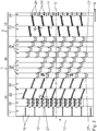
- Fig. 2 shows a development of the inside of the housing 2. This means that the hollow cylindrical housing 2 is cut along a surface line parallel to the axis of rotation 3 and is shown in one plane.
- the second end wall 12, on which the material inlet 6 is arranged is shown on the left. Accordingly, the first end wall 11 is opposite in FIG Fig. 2 shown on the right.
- the direction of rotation with which the housing 2 rotates about the axis of rotation 3 is symbolized by the arrow 13.
- the drying unit 1 has three areas along the axis of rotation 3.
- An inlet area 14 faces the second end wall 12.
- a warm area 15 faces the first end wall 11.
- a plasticizing area 16 is arranged along the axis of rotation 3 between the inlet area 14 and the warm area 15.
- the inlet area 14 is arranged first, then the plasticizing area 16 and then the warm area 15.
- the inlet area 14 has a first cone section 17, which is composed of nine cone segments 18 connected to one another.
- the first cone section 17 is designed to expand conically along the material conveying direction 9.
- the smaller cross-sectional area of the cone which is oriented perpendicular to the axis of rotation 3, is arranged on the second end wall 12 and serves as a mouth opening for the drum.
- a first protective section 19 follows the first conical section 17 along the material conveying direction 9.
- drum protectors 21 are arranged on the inside of the protective section 19.
- the drum protectors 21 are designed as elongated sheets which have an elevation along their longitudinal axis on the center line. The survey is carried out by a fold on the center line.
- the drum protectors 21 additionally have flat iron attached. This prevents the old asphalt material from coming into direct contact with the drying drum.
- the drum protectors 21 protect the inside of the protective section 19 of the drying unit 1 against wear. The service life of the drying unit 1 is increased.
- the drum protector 21 can be disassembled and replaced when worn. The replacement of the entire drying unit, which is complex and costly, is avoided.
- Two positive mixing sections 20 are arranged following the protective section 19 along the material conveying direction 9.
- the positive mixing sections 20 are essentially identical.
- Eight positive linear sheets 22 are arranged in each of the positive mixing sections 20.
- the positive linear sheets 22 are used to mix the material supplied in the drying unit 1.
- the positive linear sheets 22 serve as throwing sheets for material which has not yet been plasticized.
- the positive linear sheets 22 are designed as flat sheet metal sections which are fastened to the inside of the housing 2 with a wall spacing.
- the wall distance is in particular between 20 mm and 100 mm, in particular between 40 mm and 80 mm and in particular approximately 60 mm.
- the positive linear sheets 22 are each arranged with a positive angle of attack a p with respect to the axis of rotation 3.
- the positive angle of attack a p is 10 °.
- the positive angle of attack a p can be between 0 ° and 20 °, in particular between 5 ° and 15 °.
- the inclination of the positive linear plates 22 is oriented in the material conveying direction 9, so that material which is arranged on the positive linear plate 22 is automatically conveyed in the material conveying direction 9 due to the downward force on the positive linear plate 22 due to the force of gravity.
- the positive linear plates 22 of a positive mixing section 20 are arranged at the same distance along the inner circumference of the housing 2. It is also possible to arrange individual positive linear sheets 22 at an irregular distance from the other positive linear sheets 22, so that the intermediate area between two adjacent positive linear sheets 22 is of different sizes.
- the positive mixing sections 20 are essentially identical, in particular with an identical number of positive linear plates 22 and an identical positive angle of attack a p .
- the positive linear plates 22 of adjacent positive mixing sections 20 are arranged offset with respect to one another with respect to the direction of rotation of the axis of rotation 3. As a result, material which is conveyed in the material direction 9 by a positive linear plate 22 of the upstream positive mixing section 20 can reach the next positive linear plate 22 of the downstream positive mixing section 20. This improves material handling.
- the warm area 15 has two negative mixing sections 23.
- the negative mixing sections 23 are designed similarly to the positive mixing sections 20.
- the negative mixing sections 23 have negative linear sheets 24 which are arranged inclined at a negative angle of attack a n of -10 ° with respect to the axis of rotation.
- the negative linear plates 24 are arranged within a negative mixing section 23 at the same distance along the direction of rotation about the axis of rotation 3.
- the negative linear plates 24 of the adjacent negative mixing sections 23 are arranged offset to one another with respect to the direction of rotation about the axis of rotation 3.
- the negative linear sheets 24 are arranged at a radial distance from the inside of the drying unit 1.
- the radial distance is approximately 40 mm to 100 mm, in particular 50 mm to 90 mm and in particular 60 mm to 80 mm.
- Material that has a grain size that is smaller than the radial distance passes through the gap formed as a result of the radial distance between the negative linear plate 24 and the drying unit 1 and is conveyed due to the inclination of the drying unit 1 with respect to the horizontal 40.
- Material conglomerates that are larger than the radial distance are conveyed back into the plasticizing section 16 by the negative angle of attack a n against the material conveying direction 9 and further heated. As a result of further heating, the material conglomerates split up. The divided material conglomerates can only leave the drying unit 1 along the material conveying direction 9 when their size is smaller than the radial distance.
- the radial distance defines a maximum grain size for the material that the drying unit 1 can leave. This prevents the material conglomerates of larger diameter from leaving the drying unit 1. Sufficient warming cannot be guaranteed with large material conglomerates. Material conglomerates that are not heated to the core can cause a loss of quality in a subsequent mixing process, especially in the form of voids. Due to the arrangement of the negative linear sheets 24 with the radial spacing, such losses in quality are excluded. The quality of the material heated in the drying unit 1 is increased.
- the protective section 25 is essentially identical to the protective section 19 and has eighteen drum protectors 21.
- the axial length of the protective section 25 is reduced compared to the axial length of the protective section 19.
- the plasticizing area 16 has eight, essentially identical, plasticizing sections 26.
- Each plasticizing section 26 has a plurality of throwing plates 27 according to the exemplary embodiment 8 shown.
- the throwing plates 27 within a plasticizing section 26 are fastened to the inside of the housing 2 with equal spacing along the direction of rotation 13.
- the throwing plates 27 within a plasticizing section 26 form an annular throwing plate layer.
- the throwing sheet layers are arranged one behind the other along the axis of rotation 3.
- the throwing sheet layers are each made essentially identical, with adjacent throwing sheet layers being arranged offset to one another along the material conveying direction 9.
- the offset along the direction of rotation 13 between the throwing plates 27 of adjacent throwing plate layers can essentially be set as desired. It has been shown to be particularly advantageous that the offset is set in such a way that the arrangement of the first and fifth throwing plate layers along the material direction 9 is identical again. Accordingly, the second and the sixth throwing sheet layer, the third and the seventh throwing sheet layer and the fourth and the eighth throwing sheet layer are arranged identically with respect to their relative position along the direction of rotation 13.
- 2 fastening elements 28 are provided on the inside of the housing.
- the fastening elements 28 are in particular welded to the inside of the housing 2.
- two identically designed fastening elements 28 are provided in particular, which run along the axis of rotation 3, that is to say in a direction perpendicular to the plane of the drawing Fig. 4 are aligned.
- the fastening elements 28 are designed as metal strips.
- the fastening elements 28 have a swivel bore 29 into which a swivel pin 30 is inserted.
- the fastening elements 28 also each have a guide bore 31 into which a guide pin 32 is inserted.
- the pivot pin 30 defines a pivot axis 33 which extends parallel to the axis of rotation 3.
- the guide pin 32 is oriented along the axis of rotation 3.
- the mounting plate 34 is designed as a metal strip and has a pivot receiving bore 35 into which the pivot pin 30 projects.
- the mounting plate 34 has a slot-like guide recess 36.
- the guide recess 36 is designed in a circular arc with respect to the pivot axis 33.
- the guide pin 32 projects into the guide recess 36.
- the mounting plate 34 and the fastening element 28 are arranged along the axis of rotation 3 adjacent, in particular abutting one another.
- the diameter of the guide pin 32 essentially corresponds to the width of the guide recess 36.
- the throwing plates 27 are each inclined at an inclination angle n of 15 ° with respect to the radial direction 37.
- the angle of inclination n is at a maximum. This can be seen from the fact that the guide pin 32 is arranged on the right end of the guide recess 36. A further pivoting of the throwing plate 27 towards larger angles of inclination n is mechanically blocked. The end of the guide recess 36 forms a mechanical stop.
- the throwing plate 27 is positioned in an end position. The throwing plate 27 is in a stable arrangement.
- the maximum angle of inclination can also be greater than 15 °.
- the throwing plates 27 are arranged with a rotation angle spacing w, which in particular is identical for all throwing plates 27.
- the angle of rotation distance w can also vary.
- the guide pin 32 is designed such that any angle of inclination between 0 ° and the maximum angle of inclination, here 15 °, can be locked in a stepless manner.
- the guide pin 32 can be spring-loaded and / or be designed as a screw bolt which is locked with a fastening nut and an additional lock nut on a rear side of the mounting plate 34.
- the mounting plate 34 and the fastening element 28 are clamped, so that an inadvertent inclination of the throwing plates 27, in particular during the operation of the drying unit 1, is excluded.
- the throwing plates 27 In order to enable collision-free pivoting of the throwing plates 27, they have a bevel 38 on an end face facing the inside of the housing 2.
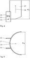
- the throwing plates 27 each define a material throwing plate conveying direction 39, which is inclined in particular according to the angle of inclination n with respect to the radial direction 37.
- the throwing plate 27 In a plane perpendicular to the material throwing plate conveying direction 39, which corresponds to the plane of the drawing Fig. 5 corresponds, the throwing plate 27 has a semicircular contour.
- the throwing plate 27 is designed as a cylinder half-shell.
- the throwing plate 27 has a concavely curved surface, so that the material can be conveyed freely along the material throwing plate conveying direction 39 and in particular along an edge-free contour. The risk of caking is reduced.
- the cylindrical half-shell shaped throwing plates 27 each have a throwing plate diameter Dw, which in the exemplary embodiment shown is between 375 mm and 500 mm. Two half-shells according to the invention can replace a classic installation.
- the throwing plates 27 have a throwing plate height Hw which, according to the exemplary embodiment shown, is between 200 mm and 600 mm.
- the throwing plate height Hw also depends on the inside diameter of the drying unit 1, which according to the exemplary embodiment shown is between 2000 mm and 3000 mm.
- drying unit 1 For drying and heating material, in particular old asphalt granulate, it is fed to the drying unit 1, in particular the housing 2, via the material inlet 6 and conveyed through the housing 2 along the material conveying direction 9. Heat is supplied from the opposite, first end wall 11 along the heat supply direction 10 by means of the burner 5, thereby heating the material.
- material in particular old asphalt granulate
- the housing 2 of the drying unit 1 is driven in rotation about the axis of rotation 3 by means of the drive 4.
- the axis of rotation 3 of the drying unit 1 is arranged, in particular, inclined with respect to the horizontal, the inclination being designed to decrease in particular from the material inlet 6 to the material outlet 7. This favors the material conveyance along the material conveying direction 9, in particular the superposition with the rotary movement of the housing 2.
- the material is slightly heated within the inlet area 14. The material is still pourable in this area. Caking practically does not occur.
- the material is heated to a critical temperature, which is between 60 ° C. and 90 ° C., in particular in the case of old asphalt granulate. Due to the heating of the material and its material properties, it becomes sticky and tends to stick.
- the material falls from a throwing plate 27 of a throwing plate layer into a throwing plate 27 of the next throwing plate layer arranged downstream. Due to the fact that the throwing plates 27 have an edge-free contour, the plasticized material becomes despite the tendency to stick along the material throwing plate conveying direction 39 substantially promoted along the throwing plate 27 without caking.
- the material conveying speed within the drum can be influenced by changing the angle of inclination n of the throwing plates 27 with respect to the radial direction 37. This makes it possible to specifically adjust the material properties of the heated material.
Landscapes
- Engineering & Computer Science (AREA)
- Mechanical Engineering (AREA)
- General Engineering & Computer Science (AREA)
- Life Sciences & Earth Sciences (AREA)
- Sustainable Development (AREA)
- Microbiology (AREA)
- Chemical & Material Sciences (AREA)
- Combustion & Propulsion (AREA)
- Drying Of Solid Materials (AREA)
- Processing And Handling Of Plastics And Other Materials For Molding In General (AREA)
- Road Paving Machines (AREA)
Claims (9)
- Unité de séchage (1) pour le séchage et/ou le chauffage d'un matériau, comprenanta. un boîtier cylindrique creux (2) pouvant être entraîné en rotation autour d'un axe de rotation (3),b. plusieurs diffuseurs (27) fixés dans le boîtier (2), lesquels diffuseurscaractérisée en ce que la direction de transport de diffuseur de matériau (39) des diffuseurs (27) est orientée transversalement à l'axe de rotation (3).i. définissent chacun une direction de transport de diffuseur de matériau (39) indépendante de l'orientation du diffuseur (27) dans l'unité de séchage (1), etii. présentent chacun un contour exempt d'arêtes, concave, dans un plan orienté perpendiculairement à la direction de transport de diffuseur de matériau (39),
- Unité de séchage selon la revendication 1, caractérisée en ce que les diffuseurs (27) sont chacun disposés réglables de manière variable dans un plan orienté perpendiculairement à l'axe de rotation (3) en ce qui concerne un angle d'inclinaison (n) par rapport à l'axe de rotation (3).
- Unité de séchage selon la revendication 1 ou 2, caractérisée en ce qu'une pluralité de diffuseurs (27) sont disposés dans un plan perpendiculaire à l'axe de rotation (3) dans une couche de diffuseurs.
- Unité de séchage selon la revendication 3, caractérisée par une pluralité de couches de diffuseurs disposées en série suivant l'axe de rotation (3).
- Unité de séchage selon la revendication 4, caractérisée en ce que les diffuseurs (27) des couches de diffuseurs adjacentes sont disposés de manière décalée les uns par rapport aux autres.
- Unité de séchage selon l'une des revendications précédentes, caractérisée en ce que les diffuseurs (27) sont disposés dans une zone de plastification (16).
- Unité de séchage selon la revendication 6, caractérisée en ce que la zone de plastification (16) est disposée suivant l'axe de rotation (3) dans la direction de transport de matériau (9) entre une zone d'entrée (14) et une zone chaude (15).
- Unité de séchage selon l'une des revendications précédentes, caractérisée en ce que le contour est semi-circulaire.
- Unité de séchage selon l'une des revendications précédentes, caractérisée en ce que le contour est constant suivant la direction de transport de diffuseur de matériau (39).
Priority Applications (1)
| Application Number | Priority Date | Filing Date | Title |
|---|---|---|---|
| PL18167705T PL3444549T3 (pl) | 2017-08-16 | 2018-04-17 | Jednostka suszarnicza z wieloma określonego rodzaju przegrodami kierującymi |
Applications Claiming Priority (1)
| Application Number | Priority Date | Filing Date | Title |
|---|---|---|---|
| DE102017214234.0A DE102017214234A1 (de) | 2017-08-16 | 2017-08-16 | Wurfblech und Trocknungseinheit mit mehreren derartigen Wurfblechen |
Publications (2)
| Publication Number | Publication Date |
|---|---|
| EP3444549A1 EP3444549A1 (fr) | 2019-02-20 |
| EP3444549B1 true EP3444549B1 (fr) | 2020-03-04 |
Family
ID=62017207
Family Applications (1)
| Application Number | Title | Priority Date | Filing Date |
|---|---|---|---|
| EP18167705.5A Active EP3444549B1 (fr) | 2017-08-16 | 2018-04-17 | Unité de séchage à une pluralité de tels diffuseurs |
Country Status (5)
| Country | Link |
|---|---|
| EP (1) | EP3444549B1 (fr) |
| DE (1) | DE102017214234A1 (fr) |
| DK (1) | DK3444549T3 (fr) |
| ES (1) | ES2784974T3 (fr) |
| PL (1) | PL3444549T3 (fr) |
Families Citing this family (3)
| Publication number | Priority date | Publication date | Assignee | Title |
|---|---|---|---|---|
| WO2020033368A1 (fr) * | 2018-08-07 | 2020-02-13 | Novelis Inc. | Raclette de four réglable pour dispositif de décapage de four rotatif et procédé associé |
| CN210103465U (zh) * | 2019-05-07 | 2020-02-21 | 内蒙古浦瑞芬环保科技有限公司 | 一种活性炭炭化回转炉 |
| EP4053484A1 (fr) * | 2021-03-05 | 2022-09-07 | S.A. Lhoist Recherche et Développement | Four rotatif et procédé de cuisson du produit contenant des carbonates, en particulier calcaire ou dolomite |
Family Cites Families (5)
| Publication number | Priority date | Publication date | Assignee | Title |
|---|---|---|---|---|
| FR871651A (fr) * | 1939-07-12 | 1942-05-05 | Metallgesellschaft Ag | Versoir pour fours tubulaires rotatifs |
| DE2120482A1 (de) * | 1971-04-27 | 1972-11-02 | Klöckner-Humboldt-Deutz AG, 5000 Köln | Verfahren und Vorrichtung zur chemischen und/oder physikalischen Behandlung von feinkörnigem Gut |
| FR2297394A1 (fr) * | 1975-01-07 | 1976-08-06 | Fives Cail Babcock | Echangeur tubulaire rotatif a transfert direct de chaleur entre un gaz et une matiere solide grenue |
| DD120272A1 (fr) * | 1975-06-18 | 1976-06-05 | ||
| AU2014284116B2 (en) * | 2013-06-20 | 2018-07-19 | Hatch Pty Ltd | Anti-segregation mixer |
-
2017
- 2017-08-16 DE DE102017214234.0A patent/DE102017214234A1/de not_active Withdrawn
-
2018
- 2018-04-17 PL PL18167705T patent/PL3444549T3/pl unknown
- 2018-04-17 DK DK18167705.5T patent/DK3444549T3/da active
- 2018-04-17 ES ES18167705T patent/ES2784974T3/es active Active
- 2018-04-17 EP EP18167705.5A patent/EP3444549B1/fr active Active
Non-Patent Citations (1)
| Title |
|---|
| None * |
Also Published As
| Publication number | Publication date |
|---|---|
| ES2784974T3 (es) | 2020-10-02 |
| DK3444549T3 (da) | 2020-05-18 |
| EP3444549A1 (fr) | 2019-02-20 |
| DE102017214234A1 (de) | 2019-02-21 |
| PL3444549T3 (pl) | 2020-07-27 |
Similar Documents
| Publication | Publication Date | Title |
|---|---|---|
| EP3444549B1 (fr) | Unité de séchage à une pluralité de tels diffuseurs | |
| EP1899070B1 (fr) | Broyeur a cylindres pour broyer des blocs de ciment brulants | |
| DE2600648C2 (de) | Pelletpresse | |
| US3244271A (en) | Auger for axially moving and laterally discharging material | |
| EP0017040B1 (fr) | Séchoir par contact à couche mince | |
| EP1929888B1 (fr) | Séchoir à tambour de l'industrie de traitement du tabac | |
| DE102005029780A1 (de) | Ofenanlage zum Anwärmen von langen Aluminiumsträngen | |
| DE3601359A1 (de) | Selbstfahrender maehdrescher | |
| EP2676538A1 (fr) | Batteuse tangentielle dotée d'un tambour de transport et d'un tambour de battage ou de séparation | |
| DE2428588C2 (de) | Vorrichtung zum Beleimen von Spänen | |
| EP2242950B1 (fr) | Installation de chauffage avec chargeur | |
| DE3928273A1 (de) | Foerdervorrichtung fuer zigaretten, filterstaebe oder deren komponenten | |
| DE19640047A1 (de) | Mähdrescher | |
| EP0367956B1 (fr) | Aube pour cylindres de refroidissement, fours à tambour rotatif ou installations similaires | |
| DE19631998C1 (de) | Drehtrommel zum Trocknen von rieselfähigem Gut | |
| DE2946904B1 (de) | Von außen beheiz- oder kühlbares, drehbares Wärmetauscherrohr zum Wärmebehandeln von pulvrigem bis körnigem, rieselfähigem, ggf. angeschlämmtem Gut | |
| DE2904997C2 (de) | Wärmebehandlungsvorrichtung mit einer Drehtrommel | |
| EP3020974B1 (fr) | Systeme de transport de milieux visqueux, procede de fonctionnement d'un tel systeme et unite de transport correspondante | |
| EP3763198A1 (fr) | Batteur d'un dispositif batteur pour moissonneuse-batteuse | |
| DE19756670C2 (de) | Einzugs-, Stütz- und Lagervorrichtung für Zerkleinerungsmaschinen | |
| DE7818690U1 (de) | Futterausgabevorrichtung fuer eine haustier-fuetterungsanlage | |
| DE2143975C3 (fr) | ||
| DE102018003555B4 (de) | Einzugswalze für eine Erntemaschine | |
| DE112022002007T5 (de) | Maschine zum auftragen von heissschmelzprodukten | |
| EP3546871B1 (fr) | Dispositif de séparation permettant de séparer une matière solide à partir d'un dflux de refoulement et procédé de maintenance d'un tel dispositif de séparation |
Legal Events
| Date | Code | Title | Description |
|---|---|---|---|
| PUAI | Public reference made under article 153(3) epc to a published international application that has entered the european phase |
Free format text: ORIGINAL CODE: 0009012 |
|
| STAA | Information on the status of an ep patent application or granted ep patent |
Free format text: STATUS: REQUEST FOR EXAMINATION WAS MADE |
|
| 17P | Request for examination filed |
Effective date: 20181214 |
|
| AK | Designated contracting states |
Kind code of ref document: A1 Designated state(s): AL AT BE BG CH CY CZ DE DK EE ES FI FR GB GR HR HU IE IS IT LI LT LU LV MC MK MT NL NO PL PT RO RS SE SI SK SM TR |
|
| AX | Request for extension of the european patent |
Extension state: BA ME |
|
| STAA | Information on the status of an ep patent application or granted ep patent |
Free format text: STATUS: EXAMINATION IS IN PROGRESS |
|
| 17Q | First examination report despatched |
Effective date: 20190411 |
|
| RIC1 | Information provided on ipc code assigned before grant |
Ipc: F27B 7/16 20060101AFI20190813BHEP Ipc: F27B 7/04 20060101ALI20190813BHEP Ipc: F26B 23/02 20060101ALI20190813BHEP Ipc: F26B 11/04 20060101ALI20190813BHEP Ipc: F26B 3/04 20060101ALI20190813BHEP |
|
| GRAP | Despatch of communication of intention to grant a patent |
Free format text: ORIGINAL CODE: EPIDOSNIGR1 |
|
| STAA | Information on the status of an ep patent application or granted ep patent |
Free format text: STATUS: GRANT OF PATENT IS INTENDED |
|
| INTG | Intention to grant announced |
Effective date: 20190925 |
|
| GRAS | Grant fee paid |
Free format text: ORIGINAL CODE: EPIDOSNIGR3 |
|
| GRAA | (expected) grant |
Free format text: ORIGINAL CODE: 0009210 |
|
| STAA | Information on the status of an ep patent application or granted ep patent |
Free format text: STATUS: THE PATENT HAS BEEN GRANTED |
|
| AK | Designated contracting states |
Kind code of ref document: B1 Designated state(s): AL AT BE BG CH CY CZ DE DK EE ES FI FR GB GR HR HU IE IS IT LI LT LU LV MC MK MT NL NO PL PT RO RS SE SI SK SM TR |
|
| REG | Reference to a national code |
Ref country code: GB Ref legal event code: FG4D Free format text: NOT ENGLISH |
|
| REG | Reference to a national code |
Ref country code: CH Ref legal event code: EP |
|
| REG | Reference to a national code |
Ref country code: AT Ref legal event code: REF Ref document number: 1240861 Country of ref document: AT Kind code of ref document: T Effective date: 20200315 |
|
| REG | Reference to a national code |
Ref country code: DE Ref legal event code: R096 Ref document number: 502018000868 Country of ref document: DE |
|
| REG | Reference to a national code |
Ref country code: IE Ref legal event code: FG4D Free format text: LANGUAGE OF EP DOCUMENT: GERMAN |
|
| REG | Reference to a national code |
Ref country code: FI Ref legal event code: FGE |
|
| REG | Reference to a national code |
Ref country code: DK Ref legal event code: T3 Effective date: 20200514 |
|
| PG25 | Lapsed in a contracting state [announced via postgrant information from national office to epo] |
Ref country code: RS Free format text: LAPSE BECAUSE OF FAILURE TO SUBMIT A TRANSLATION OF THE DESCRIPTION OR TO PAY THE FEE WITHIN THE PRESCRIBED TIME-LIMIT Effective date: 20200304 Ref country code: NO Free format text: LAPSE BECAUSE OF FAILURE TO SUBMIT A TRANSLATION OF THE DESCRIPTION OR TO PAY THE FEE WITHIN THE PRESCRIBED TIME-LIMIT Effective date: 20200604 |
|
| REG | Reference to a national code |
Ref country code: NL Ref legal event code: MP Effective date: 20200304 |
|
| PG25 | Lapsed in a contracting state [announced via postgrant information from national office to epo] |
Ref country code: SE Free format text: LAPSE BECAUSE OF FAILURE TO SUBMIT A TRANSLATION OF THE DESCRIPTION OR TO PAY THE FEE WITHIN THE PRESCRIBED TIME-LIMIT Effective date: 20200304 Ref country code: LV Free format text: LAPSE BECAUSE OF FAILURE TO SUBMIT A TRANSLATION OF THE DESCRIPTION OR TO PAY THE FEE WITHIN THE PRESCRIBED TIME-LIMIT Effective date: 20200304 Ref country code: BG Free format text: LAPSE BECAUSE OF FAILURE TO SUBMIT A TRANSLATION OF THE DESCRIPTION OR TO PAY THE FEE WITHIN THE PRESCRIBED TIME-LIMIT Effective date: 20200604 Ref country code: GR Free format text: LAPSE BECAUSE OF FAILURE TO SUBMIT A TRANSLATION OF THE DESCRIPTION OR TO PAY THE FEE WITHIN THE PRESCRIBED TIME-LIMIT Effective date: 20200605 Ref country code: HR Free format text: LAPSE BECAUSE OF FAILURE TO SUBMIT A TRANSLATION OF THE DESCRIPTION OR TO PAY THE FEE WITHIN THE PRESCRIBED TIME-LIMIT Effective date: 20200304 |
|
| REG | Reference to a national code |
Ref country code: LT Ref legal event code: MG4D |
|
| PG25 | Lapsed in a contracting state [announced via postgrant information from national office to epo] |
Ref country code: NL Free format text: LAPSE BECAUSE OF FAILURE TO SUBMIT A TRANSLATION OF THE DESCRIPTION OR TO PAY THE FEE WITHIN THE PRESCRIBED TIME-LIMIT Effective date: 20200304 |
|
| REG | Reference to a national code |
Ref country code: ES Ref legal event code: FG2A Ref document number: 2784974 Country of ref document: ES Kind code of ref document: T3 Effective date: 20201002 |
|
| PG25 | Lapsed in a contracting state [announced via postgrant information from national office to epo] |
Ref country code: RO Free format text: LAPSE BECAUSE OF FAILURE TO SUBMIT A TRANSLATION OF THE DESCRIPTION OR TO PAY THE FEE WITHIN THE PRESCRIBED TIME-LIMIT Effective date: 20200304 Ref country code: SK Free format text: LAPSE BECAUSE OF FAILURE TO SUBMIT A TRANSLATION OF THE DESCRIPTION OR TO PAY THE FEE WITHIN THE PRESCRIBED TIME-LIMIT Effective date: 20200304 Ref country code: IS Free format text: LAPSE BECAUSE OF FAILURE TO SUBMIT A TRANSLATION OF THE DESCRIPTION OR TO PAY THE FEE WITHIN THE PRESCRIBED TIME-LIMIT Effective date: 20200704 Ref country code: SM Free format text: LAPSE BECAUSE OF FAILURE TO SUBMIT A TRANSLATION OF THE DESCRIPTION OR TO PAY THE FEE WITHIN THE PRESCRIBED TIME-LIMIT Effective date: 20200304 Ref country code: PT Free format text: LAPSE BECAUSE OF FAILURE TO SUBMIT A TRANSLATION OF THE DESCRIPTION OR TO PAY THE FEE WITHIN THE PRESCRIBED TIME-LIMIT Effective date: 20200729 Ref country code: EE Free format text: LAPSE BECAUSE OF FAILURE TO SUBMIT A TRANSLATION OF THE DESCRIPTION OR TO PAY THE FEE WITHIN THE PRESCRIBED TIME-LIMIT Effective date: 20200304 Ref country code: LT Free format text: LAPSE BECAUSE OF FAILURE TO SUBMIT A TRANSLATION OF THE DESCRIPTION OR TO PAY THE FEE WITHIN THE PRESCRIBED TIME-LIMIT Effective date: 20200304 Ref country code: CZ Free format text: LAPSE BECAUSE OF FAILURE TO SUBMIT A TRANSLATION OF THE DESCRIPTION OR TO PAY THE FEE WITHIN THE PRESCRIBED TIME-LIMIT Effective date: 20200304 |
|
| REG | Reference to a national code |
Ref country code: DE Ref legal event code: R097 Ref document number: 502018000868 Country of ref document: DE |
|
| PG25 | Lapsed in a contracting state [announced via postgrant information from national office to epo] |
Ref country code: MC Free format text: LAPSE BECAUSE OF FAILURE TO SUBMIT A TRANSLATION OF THE DESCRIPTION OR TO PAY THE FEE WITHIN THE PRESCRIBED TIME-LIMIT Effective date: 20200304 |
|
| PLBE | No opposition filed within time limit |
Free format text: ORIGINAL CODE: 0009261 |
|
| STAA | Information on the status of an ep patent application or granted ep patent |
Free format text: STATUS: NO OPPOSITION FILED WITHIN TIME LIMIT |
|
| PG25 | Lapsed in a contracting state [announced via postgrant information from national office to epo] |
Ref country code: LU Free format text: LAPSE BECAUSE OF NON-PAYMENT OF DUE FEES Effective date: 20200417 |
|
| REG | Reference to a national code |
Ref country code: BE Ref legal event code: MM Effective date: 20200430 |
|
| 26N | No opposition filed |
Effective date: 20201207 |
|
| PG25 | Lapsed in a contracting state [announced via postgrant information from national office to epo] |
Ref country code: BE Free format text: LAPSE BECAUSE OF NON-PAYMENT OF DUE FEES Effective date: 20200430 Ref country code: SI Free format text: LAPSE BECAUSE OF FAILURE TO SUBMIT A TRANSLATION OF THE DESCRIPTION OR TO PAY THE FEE WITHIN THE PRESCRIBED TIME-LIMIT Effective date: 20200304 |
|
| PG25 | Lapsed in a contracting state [announced via postgrant information from national office to epo] |
Ref country code: IE Free format text: LAPSE BECAUSE OF NON-PAYMENT OF DUE FEES Effective date: 20200417 |
|
| PGFP | Annual fee paid to national office [announced via postgrant information from national office to epo] |
Ref country code: ES Payment date: 20210519 Year of fee payment: 4 |
|
| REG | Reference to a national code |
Ref country code: DE Ref legal event code: R081 Ref document number: 502018000868 Country of ref document: DE Owner name: BENNINGHOVEN ZWEIGNIEDERLASSUNG DER WIRTGEN MI, DE Free format text: FORMER OWNER: BENNINGHOVEN GMBH & CO. KG, 54516 WITTLICH, DE |
|
| PG25 | Lapsed in a contracting state [announced via postgrant information from national office to epo] |
Ref country code: MT Free format text: LAPSE BECAUSE OF FAILURE TO SUBMIT A TRANSLATION OF THE DESCRIPTION OR TO PAY THE FEE WITHIN THE PRESCRIBED TIME-LIMIT Effective date: 20200304 Ref country code: CY Free format text: LAPSE BECAUSE OF FAILURE TO SUBMIT A TRANSLATION OF THE DESCRIPTION OR TO PAY THE FEE WITHIN THE PRESCRIBED TIME-LIMIT Effective date: 20200304 |
|
| PG25 | Lapsed in a contracting state [announced via postgrant information from national office to epo] |
Ref country code: MK Free format text: LAPSE BECAUSE OF FAILURE TO SUBMIT A TRANSLATION OF THE DESCRIPTION OR TO PAY THE FEE WITHIN THE PRESCRIBED TIME-LIMIT Effective date: 20200304 Ref country code: AL Free format text: LAPSE BECAUSE OF FAILURE TO SUBMIT A TRANSLATION OF THE DESCRIPTION OR TO PAY THE FEE WITHIN THE PRESCRIBED TIME-LIMIT Effective date: 20200304 |
|
| REG | Reference to a national code |
Ref country code: ES Ref legal event code: FD2A Effective date: 20230526 |
|
| PGFP | Annual fee paid to national office [announced via postgrant information from national office to epo] |
Ref country code: PL Payment date: 20230316 Year of fee payment: 6 |
|
| P01 | Opt-out of the competence of the unified patent court (upc) registered |
Effective date: 20230517 |
|
| PG25 | Lapsed in a contracting state [announced via postgrant information from national office to epo] |
Ref country code: ES Free format text: LAPSE BECAUSE OF NON-PAYMENT OF DUE FEES Effective date: 20220418 |
|
| PGFP | Annual fee paid to national office [announced via postgrant information from national office to epo] |
Ref country code: IT Payment date: 20230428 Year of fee payment: 6 Ref country code: FR Payment date: 20230417 Year of fee payment: 6 Ref country code: DK Payment date: 20230419 Year of fee payment: 6 Ref country code: DE Payment date: 20230629 Year of fee payment: 6 Ref country code: CH Payment date: 20230501 Year of fee payment: 6 |
|
| PGFP | Annual fee paid to national office [announced via postgrant information from national office to epo] |
Ref country code: TR Payment date: 20230414 Year of fee payment: 6 Ref country code: FI Payment date: 20230417 Year of fee payment: 6 |
|
| PGFP | Annual fee paid to national office [announced via postgrant information from national office to epo] |
Ref country code: GB Payment date: 20230420 Year of fee payment: 6 |