EP3444540A2 - Transkritisches dampfverdichtersystem mit rückführung von wiedergewonnener überhitzung - Google Patents
Transkritisches dampfverdichtersystem mit rückführung von wiedergewonnener überhitzung Download PDFInfo
- Publication number
- EP3444540A2 EP3444540A2 EP18188470.1A EP18188470A EP3444540A2 EP 3444540 A2 EP3444540 A2 EP 3444540A2 EP 18188470 A EP18188470 A EP 18188470A EP 3444540 A2 EP3444540 A2 EP 3444540A2
- Authority
- EP
- European Patent Office
- Prior art keywords
- coolant
- vapor
- compressor
- pressure side
- liquid
- Prior art date
- Legal status (The legal status is an assumption and is not a legal conclusion. Google has not performed a legal analysis and makes no representation as to the accuracy of the status listed.)
- Withdrawn
Links
Images


Classifications
-
- F—MECHANICAL ENGINEERING; LIGHTING; HEATING; WEAPONS; BLASTING
- F25—REFRIGERATION OR COOLING; COMBINED HEATING AND REFRIGERATION SYSTEMS; HEAT PUMP SYSTEMS; MANUFACTURE OR STORAGE OF ICE; LIQUEFACTION SOLIDIFICATION OF GASES
- F25B—REFRIGERATION MACHINES, PLANTS OR SYSTEMS; COMBINED HEATING AND REFRIGERATION SYSTEMS; HEAT PUMP SYSTEMS
- F25B40/00—Subcoolers, desuperheaters or superheaters
-
- F—MECHANICAL ENGINEERING; LIGHTING; HEATING; WEAPONS; BLASTING
- F25—REFRIGERATION OR COOLING; COMBINED HEATING AND REFRIGERATION SYSTEMS; HEAT PUMP SYSTEMS; MANUFACTURE OR STORAGE OF ICE; LIQUEFACTION SOLIDIFICATION OF GASES
- F25B—REFRIGERATION MACHINES, PLANTS OR SYSTEMS; COMBINED HEATING AND REFRIGERATION SYSTEMS; HEAT PUMP SYSTEMS
- F25B9/00—Compression machines, plants or systems, in which the refrigerant is air or other gas of low boiling point
- F25B9/10—Compression machines, plants or systems, in which the refrigerant is air or other gas of low boiling point with several cooling stages
-
- F—MECHANICAL ENGINEERING; LIGHTING; HEATING; WEAPONS; BLASTING
- F25—REFRIGERATION OR COOLING; COMBINED HEATING AND REFRIGERATION SYSTEMS; HEAT PUMP SYSTEMS; MANUFACTURE OR STORAGE OF ICE; LIQUEFACTION SOLIDIFICATION OF GASES
- F25B—REFRIGERATION MACHINES, PLANTS OR SYSTEMS; COMBINED HEATING AND REFRIGERATION SYSTEMS; HEAT PUMP SYSTEMS
- F25B49/00—Arrangement or mounting of control or safety devices
- F25B49/02—Arrangement or mounting of control or safety devices for compression type machines, plants or systems
-
- F—MECHANICAL ENGINEERING; LIGHTING; HEATING; WEAPONS; BLASTING
- F25—REFRIGERATION OR COOLING; COMBINED HEATING AND REFRIGERATION SYSTEMS; HEAT PUMP SYSTEMS; MANUFACTURE OR STORAGE OF ICE; LIQUEFACTION SOLIDIFICATION OF GASES
- F25B—REFRIGERATION MACHINES, PLANTS OR SYSTEMS; COMBINED HEATING AND REFRIGERATION SYSTEMS; HEAT PUMP SYSTEMS
- F25B9/00—Compression machines, plants or systems, in which the refrigerant is air or other gas of low boiling point
- F25B9/002—Compression machines, plants or systems, in which the refrigerant is air or other gas of low boiling point characterised by the refrigerant
- F25B9/008—Compression machines, plants or systems, in which the refrigerant is air or other gas of low boiling point characterised by the refrigerant the refrigerant being carbon dioxide
-
- F—MECHANICAL ENGINEERING; LIGHTING; HEATING; WEAPONS; BLASTING
- F25—REFRIGERATION OR COOLING; COMBINED HEATING AND REFRIGERATION SYSTEMS; HEAT PUMP SYSTEMS; MANUFACTURE OR STORAGE OF ICE; LIQUEFACTION SOLIDIFICATION OF GASES
- F25B—REFRIGERATION MACHINES, PLANTS OR SYSTEMS; COMBINED HEATING AND REFRIGERATION SYSTEMS; HEAT PUMP SYSTEMS
- F25B2309/00—Gas cycle refrigeration machines
- F25B2309/06—Compression machines, plants or systems characterised by the refrigerant being carbon dioxide
- F25B2309/061—Compression machines, plants or systems characterised by the refrigerant being carbon dioxide with cycle highest pressure above the supercritical pressure
-
- F—MECHANICAL ENGINEERING; LIGHTING; HEATING; WEAPONS; BLASTING
- F25—REFRIGERATION OR COOLING; COMBINED HEATING AND REFRIGERATION SYSTEMS; HEAT PUMP SYSTEMS; MANUFACTURE OR STORAGE OF ICE; LIQUEFACTION SOLIDIFICATION OF GASES
- F25B—REFRIGERATION MACHINES, PLANTS OR SYSTEMS; COMBINED HEATING AND REFRIGERATION SYSTEMS; HEAT PUMP SYSTEMS
- F25B2341/00—Details of ejectors not being used as compression device; Details of flow restrictors or expansion valves
- F25B2341/001—Ejectors not being used as compression device
-
- F—MECHANICAL ENGINEERING; LIGHTING; HEATING; WEAPONS; BLASTING
- F25—REFRIGERATION OR COOLING; COMBINED HEATING AND REFRIGERATION SYSTEMS; HEAT PUMP SYSTEMS; MANUFACTURE OR STORAGE OF ICE; LIQUEFACTION SOLIDIFICATION OF GASES
- F25B—REFRIGERATION MACHINES, PLANTS OR SYSTEMS; COMBINED HEATING AND REFRIGERATION SYSTEMS; HEAT PUMP SYSTEMS
- F25B2341/00—Details of ejectors not being used as compression device; Details of flow restrictors or expansion valves
- F25B2341/001—Ejectors not being used as compression device
- F25B2341/0011—Ejectors with the cooled primary flow at reduced or low pressure
-
- F—MECHANICAL ENGINEERING; LIGHTING; HEATING; WEAPONS; BLASTING
- F25—REFRIGERATION OR COOLING; COMBINED HEATING AND REFRIGERATION SYSTEMS; HEAT PUMP SYSTEMS; MANUFACTURE OR STORAGE OF ICE; LIQUEFACTION SOLIDIFICATION OF GASES
- F25B—REFRIGERATION MACHINES, PLANTS OR SYSTEMS; COMBINED HEATING AND REFRIGERATION SYSTEMS; HEAT PUMP SYSTEMS
- F25B2400/00—Component parts or details not otherwise provided for in this subclass
- F25B2400/05—Compression system with heat exchange between particular parts of the system
- F25B2400/054—Compression system with heat exchange between particular parts of the system between the suction tube of the compressor and another part of the cycle
-
- F—MECHANICAL ENGINEERING; LIGHTING; HEATING; WEAPONS; BLASTING
- F25—REFRIGERATION OR COOLING; COMBINED HEATING AND REFRIGERATION SYSTEMS; HEAT PUMP SYSTEMS; MANUFACTURE OR STORAGE OF ICE; LIQUEFACTION SOLIDIFICATION OF GASES
- F25B—REFRIGERATION MACHINES, PLANTS OR SYSTEMS; COMBINED HEATING AND REFRIGERATION SYSTEMS; HEAT PUMP SYSTEMS
- F25B2400/00—Component parts or details not otherwise provided for in this subclass
- F25B2400/23—Separators
-
- F—MECHANICAL ENGINEERING; LIGHTING; HEATING; WEAPONS; BLASTING
- F25—REFRIGERATION OR COOLING; COMBINED HEATING AND REFRIGERATION SYSTEMS; HEAT PUMP SYSTEMS; MANUFACTURE OR STORAGE OF ICE; LIQUEFACTION SOLIDIFICATION OF GASES
- F25B—REFRIGERATION MACHINES, PLANTS OR SYSTEMS; COMBINED HEATING AND REFRIGERATION SYSTEMS; HEAT PUMP SYSTEMS
- F25B2600/00—Control issues
- F25B2600/25—Control of valves
- F25B2600/2515—Flow valves
-
- F—MECHANICAL ENGINEERING; LIGHTING; HEATING; WEAPONS; BLASTING
- F25—REFRIGERATION OR COOLING; COMBINED HEATING AND REFRIGERATION SYSTEMS; HEAT PUMP SYSTEMS; MANUFACTURE OR STORAGE OF ICE; LIQUEFACTION SOLIDIFICATION OF GASES
- F25B—REFRIGERATION MACHINES, PLANTS OR SYSTEMS; COMBINED HEATING AND REFRIGERATION SYSTEMS; HEAT PUMP SYSTEMS
- F25B2600/00—Control issues
- F25B2600/25—Control of valves
- F25B2600/2517—Head-pressure valves
-
- F—MECHANICAL ENGINEERING; LIGHTING; HEATING; WEAPONS; BLASTING
- F25—REFRIGERATION OR COOLING; COMBINED HEATING AND REFRIGERATION SYSTEMS; HEAT PUMP SYSTEMS; MANUFACTURE OR STORAGE OF ICE; LIQUEFACTION SOLIDIFICATION OF GASES
- F25B—REFRIGERATION MACHINES, PLANTS OR SYSTEMS; COMBINED HEATING AND REFRIGERATION SYSTEMS; HEAT PUMP SYSTEMS
- F25B41/00—Fluid-circulation arrangements
-
- F—MECHANICAL ENGINEERING; LIGHTING; HEATING; WEAPONS; BLASTING
- F41—WEAPONS
- F41B—WEAPONS FOR PROJECTING MISSILES WITHOUT USE OF EXPLOSIVE OR COMBUSTIBLE PROPELLANT CHARGE; WEAPONS NOT OTHERWISE PROVIDED FOR
- F41B6/00—Electromagnetic launchers ; Plasma-actuated launchers
- F41B6/006—Rail launchers
-
- F—MECHANICAL ENGINEERING; LIGHTING; HEATING; WEAPONS; BLASTING
- F41—WEAPONS
- F41H—ARMOUR; ARMOURED TURRETS; ARMOURED OR ARMED VEHICLES; MEANS OF ATTACK OR DEFENCE, e.g. CAMOUFLAGE, IN GENERAL
- F41H13/00—Means of attack or defence not otherwise provided for
- F41H13/0043—Directed energy weapons, i.e. devices that direct a beam of high energy content toward a target for incapacitating or destroying the target
Definitions
- This disclosure relates to cooling systems.
- LPR Low Pressure Receiver
- One or more primary system evaporators in the LPR architecture may exhaust into a low pressure receiver (a type of vapor-liquid separator) before flow continues on to a compressor.
- the low pressure receiver may need to be large enough to remove saturated liquid in the flow to the compressor. Otherwise, liquid remaining in the flow to the compressor may cause serious problems in the compressor. For example, liquid that settles in the oil of the compressor may boil, which may then cause oil to foam and enter a compression chamber of the compressor.
- Including an over-sized low pressure receiver may help eliminate saturated liquid in the flow to the compressor.
- a coolant is supplied in a vapor state to a compressor.
- the coolant compressed by the compressor is cooled with a gas cooler.
- the coolant cooled by the gas cooler is supplied to an inlet of a high pressure side of a recuperator.
- the coolant from an outlet of the high pressure side of the recuperator is supplied to a portion of a coolant circuit.
- the coolant is supplied back from the portion of the coolant circuit to an inlet of a low pressure side of the recuperator.
- the coolant in the low pressure side of the recuperator is heated with thermal energy transferred by the recuperator from the coolant in the high pressure side of the recuperator.
- the coolant in the vapor state from an outlet of the low pressure side of the recuperator is supplied to the compressor.
- the invention may relate to a cooling system comprising:
- the second portion of the coolant circuit may include a vapor-liquid separator having a liquid outlet and a vapor outlet, and the second portion of the coolant circuit is configured to return the coolant, which includes coolant that exits the liquid outlet of the vapor-liquid separator, to the low pressure side of the recuperator.
- the second portion of the coolant circuit may include a means for creating a pressure drop
- the means includes an inlet and an outlet, wherein the means is configured to create the pressure drop between the inlet and the outlet of the means, and wherein the inlet of the means is configured to receive a vapor portion of the coolant through the vapor outlet of the vapor-liquid separator, and wherein the coolant that the second portion of the coolant circuit is configured to return to the low pressure side of the recuperator includes a mixture of the vapor portion of the coolant supplied through the outlet of the means and a liquid portion of the coolant received through the liquid outlet of the vapor-liquid separator.
- the means for creating the pressure drop may include a venturi valve configured to create the pressure drop.
- the venturi valve may be configured to mix the first portion of the coolant and the second portion of the coolant.
- the second portion of the coolant circuit may further include a liquid return valve, and the liquid return valve is configured to control a flow of the liquid portion of the coolant.
- a processor may be configured to cause the liquid return valve to adjust the flow of the second portion of the coolant based on a temperature of the coolant supplied to the compressor.
- a processor may be configured to cause the liquid return valve to adjust the flow of the second portion of the coolant such that a temperature of the coolant supplied to the compressor indicates that the coolant is supplied to the compressor in the vapor state.
- the invention may relate to a method comprising at least the following steps:
- the method may comprise further the steps of reducing a pressure of a vapor portion of the coolant to a reduced pressure, the vapor portion of the coolant received through a vapor outlet of a vapor-liquid separator included in the portion of the coolant circuit;
- reducing the pressure and the mixing may be performed by a venturi valve.
- adjusting the flow of the liquid portion may comprise decreasing the flow in response to a decrease in a thermal load cooled by the coolant.
- adjusting the flow of the liquid portion may comprise increasing the flow in response to an increase in a thermal load cooled by the coolant.
- adjusting the flow of the liquid portion may comprise increasing the flow in response to a temperature of the coolant supplied to the compressor exceeding a threshold value.
- adjusting the flow of the liquid portion may comprise decreasing the flow in response to a temperature of the coolant supplied to the compressor falling below a threshold value.
- the invention may relate to a cooling system comprising at least:
- the pressure drop element and the mixer may be integral components of an eductor or an ejector.
- the thermal load may be imposed by a directed-energy weapon.
- the evaporator may be configured to cool at least two independent coolant loops with a single set of conduits that transport the coolant through sections of the evaporator that correspond to the at least two independent coolant loops.
- the at least two independent coolant loops may comprise a hotel coolant loop and a primary coolant loop.
- the system includes a compressor, a gas cooler, a recuperator, a thermal expansion valve, an evaporator, a vapor-liquid separator, a liquid return valve, a pressure drop element, and a mixer.
- the compressor may compress a coolant that is supplied to the compressor in a vapor state.
- the gas cooler may cool the coolant compressed by the compressor.
- the recuperator may have a high pressure side and a low pressure side that are fluidly isolated from each other. Thermal energy may be transferred from the high pressure side of the recuperator to the low pressure side, thereby cooling coolant in the high pressure side and heating coolant in the low pressure side.
- the recuperator may receive the coolant cooled by the gas cooler at an inlet of the high pressure side.
- the coolant in the high pressure side is cooled in the recuperator when the thermal energy is transferred to the low pressure side.
- the coolant in the low pressure side is heated to a vapor state.
- the coolant in the vapor state may be supplied to the compressor from an outlet of the low pressure side.
- the thermal expansion valve may receive the coolant cooled by the recuperator from an outlet of the high pressure side of the recuperator.
- the evaporator may receive the coolant from the thermal expansion valve and cool a thermal load with the coolant.
- the vapor-liquid separator may receive the coolant from the evaporator and separate the coolant into a vapor portion and a liquid portion.
- the liquid return valve may control a flow of the liquid portion out of the vapor-liquid separator.
- the pressure drop element may cause the pressure of the vapor portion of the coolant that exits the vapor-liquid separator to drop to a decreased pressure.
- the mixer may form a mixture of the vapor portion of the coolant at the decreased pressure and the liquid portion of the coolant received through the liquid return valve.
- the recuperator may receive the mixture at an inlet of the low pressure side of the recuperator.
- an interesting feature of the systems and methods described below may be that liquid coolant entering the compressor may be avoided. Alternatively, or in addition, an interesting feature of the systems and methods described below may be that a smaller and/or a less efficient vapor-liquid separator may be utilized than in some other systems. Alternatively, or in addition, an interesting feature of the systems and methods described below may be mass may be returned to the system more rapidly than in some other systems so as to more rapidly adjust to sudden onset of high thermal loads. Alternatively, or in addition, an interesting feature of the systems and methods described below may be to improve a Coefficient of Performance at high heat rejection temperature and/or pressure.
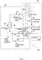
- FIG. 1 is a schematic diagram of an example of a cooling system 100 that has a recuperated superheat return architecture.
- the cooling system 100 shown in FIG. 1 includes a compressor 102, a gas cooler 104, a recuperator 106, a thermal expansion valve 108, an evaporator 110, a vapor-liquid separator 112 (for example, a low pressure receiver), a liquid return valve 114, a pressure drop device 116, and a mixer 118.
- the system 100 may include additional, fewer, and/or different components than the example shown in FIG. 1 .
- the pressure drop device 116 may include a means for creating a pressure drop.
- the pressure drop device 116 may create the pressure drop between an inlet of the pressure drop device 116 and an outlet of the pressure drop device 116.
- Examples of the pressure drop device 116 may include a restriction, a length of pipe or tubing, a pipe or a tubing having a cross-sectional area change, a pipe or a tubing including an obstruction, an orifice, a valve, a bent pipe, an automated valve, a venturi valve, and/or any other physical structure that causes a pressure drop on a fluid as the fluid flows through the physical structure.
- the pressure drop device 116 may be a passive device and/or an active device.
- the vapor-liquid separator 112 may include any device configured to separate a vapor-liquid mixture into vapor and liquid portions.
- the vapor-liquid separator 112 may be a vessel in which gravity causes the liquid portion to settle to a bottom portion of the vessel and the vapor portion to rise to a top portion of the vessel.
- the vapor-liquid separator 112 may use centrifugal force to drive the liquid portion towards an outer edge of the vessel for removal and the vapor portion may migrate towards a center region of the vessel.
- the vapor-liquid separator 112 may include a level sensor mechanism that monitors a level of the liquid in the vessel. Examples of the vapor-liquid separator may include a low pressure receiver and a flash tank.
- the compressor 102 may be any mechanical device that increases a pressure of a gas by reducing the volume of the gas.
- Examples of the compressor 102 may include any gas compressor, such as a positive displacement compressor, a dynamic compressor, a rotary compressor, a reciprocating compressor, a centrifugal compressor, an axial compressor, and/or any combination thereof.
- the mixer 118 may be any device that combines fluid received in two or more inlets into fluid that exits an outlet.
- An example of the mixer 118 includes a junction.
- the compressor 102, the gas cooler 104, the recuperator 106, the thermal expansion valve 108, the evaporator 110, the vapor-liquid separator 112, the liquid return valve 114, the pressure drop device 116, and the mixer 118 may be in fluid communication with each other and form a coolant circuit through which a coolant may flow.
- Tubing may connect the components of the coolant circuit.
- a high pressure side of the coolant circuit may be a portion that extends from an outlet of the compressor 102 to an inlet of the thermal expansion valve 108.
- a low pressure side of the coolant circuit may be a portion that extends from an outlet of the thermal expansion valve 108 to an inlet of the compressor 102.
- a first portion 120 of the coolant circuit may include the compressor 102, the gas cooler 104, and the recuperator 106.
- a second portion 122 of the coolant circuit may include the thermal expansion valve 108, the evaporator 110, the vapor-liquid separator 112, the liquid return valve 114, the pressure drop device 116, and the mixer 118.
- the coolant may be any substance suitable for cooling systems.
- the coolant or refrigerant may be any substance suitable for a trans-critical cooling system and/or a sub-critical cooling system.
- Examples of the coolant may include carbon dioxide (CO 2 ), anhydrous ammonia, a halomethane, a haloalkane, a hydrofluorocarbon (HFC), chlorofluorocarbons (CFC), a hydrochlorofluorocarbon (HCFC), any two-phase refrigerants, and/or a nanofluid.
- the compressor 102 may compress the coolant, which is supplied to the compressor in a vapor state.
- the coolant compressed by the compressor 102 may flow to the gas cooler 104.
- the compressed coolant may flow through an oil separator 124 to the gas cooler 104.
- the oil separator 124 may separate oil from the compressed coolant and return the oil to the compressor 102.
- the gas cooler 104 may cool the coolant compressed by the compressor 102.
- the coolant cooled by the gas cooler 104 may flow to the recuperator 106.
- the recuperator 106 may have a high pressure side and a low pressure side.
- the recuperator 106 may include a heat exchanger that transfers heat from the coolant on the high pressure side to the coolant on the low pressure side.
- the recuperator 106 may receive the coolant cooled by the gas cooler 104 at an inlet 126 of the high pressure side and supply the coolant to the second portion 122 of the coolant circuit from an outlet 128 of the high pressure side.
- the recuperator 106 may receive the coolant returned by the second portion 122 of coolant circuit at an inlet 130 of the low pressure side of the recuperator 106.
- the recuperator 106 may supply the coolant to the compressor 102 from an outlet 132 of the low pressure side of the recuperator 106.
- the recuperator 106 may cause the coolant to exit the outlet 132 of the low pressure side in a vapor state. Due to thermal energy transferred to the coolant before the coolant flows out of the outlet 132 of the low pressure side to the compressor, the compressor 102 receives the coolant from the recuperator 106 in the vapor state and, in some examples, superheated.
- the coolant may flow from the outlet 128 of the high pressure side of the recuperator 106 to the thermal expansion valve 108.
- the coolant exits the thermal expansion valve 108 and flows to the evaporator 110.
- the evaporator 110 may cool a thermal load 134.
- the thermal expansion valve 108 may regulate a high pressure and/or mass flow in the system 100 to control Coefficients of Performance (COP) and/or evaporator heat duty.
- COP Coefficients of Performance
- the system 100 may include one or more processors 140 configured to cause the thermal expansion valve 108 to regulate the high pressure side, regulate compressor speed, regulate liquid return, regulate oil return from the oil separator and regulate condenser fan(s) speed.
- the coolant that exits the gas cooler 104 may be cooled or sub-cooled prior to entering the thermal expansion valve 108.
- This cooling results in lowering the vapor quality in the flow to the evaporator 110.
- the lower vapor quality in the coolant entering the evaporator 110 may make for better liquid distribution and improved evaporator performance than without the lower vapor quality.
- the evaporator 110 may be physically smaller than an evaporator that receives the coolant without the lowered vapor quality and yet still have the same cooling capacity as the larger evaporator.
- the coolant that exits the evaporator 110 flows into an inlet of the vapor-liquid separator 112.
- the coolant separates into a liquid and a vapor in the vapor-liquid separator 112.
- the vapor-liquid separator 112 includes a liquid outlet 136 and a vapor outlet 138.
- An inlet of the pressure drop device 116 receives a first portion of the coolant through the vapor outlet 138 of the vapor-liquid separator 112.
- An inlet of the liquid return valve 114 receives a second portion of the coolant through the liquid outlet 136 of the vapor-liquid separator 112.
- the first portion of the coolant exits an outlet of the pressure drop device 116 at a lower pressure than at the inlet of the pressure drop device.
- the second portion of the coolant exits an outlet of the liquid return valve 114.
- the mixer 118 mixes the first portion of the coolant with the second portion of the coolant to form a mixture.
- An outlet of the mixer 118 may supply the mixture of the first portion of the coolant and the second portion of the coolant to the inlet 130 of the low pressure side of the recuperator 106.
- the pressure drop created by the pressure drop device 116 may aid in causing the coolant to flow to the recuperator 106 without relying on gravity to cause the flow.
- the pressure drop device 116 and the mixer 118 may be one device.
- the pressure drop device 116 may be an eductor, an ejector, and/or a venturi valve that receives the first portion of the coolant through the vapor outlet 138 of the vapor-liquid separator 112 and the second portion of the coolant through the outlet of the liquid return valve 114.
- An outlet of the eductor, the ejector, and/or the venturi valve may supply the mixture of the first portion of the coolant and the second portion of the coolant to the recuperator 106.
- the second portion 122 of the coolant circuit is configured to return to the inlet 130 of the low pressure side of the recuperator 106 the mixture of the first portion of the coolant released at the outlet of the pressure drop device 116 and the second portion of the coolant supplied by the liquid outlet 136 of the vapor-liquid separator 112.
- the coolant entering the inlet 130 of the low pressure side of the recuperator 106 may include liquid.
- the coolant entering the inlet 130 of the low pressure side may include as much as, for example, twenty percent liquid by mass, and the coolant entering the compressor 102 may be, nevertheless, in a vapor state due to the heat transferred to the coolant by the recuperator 106. Accordingly, the physical size of the vapor-liquid separator 112 may be smaller than if the system 100 did not transfer the heat to the coolant with the recuperator 106.
- the processor 140 may be configured to cause the liquid return valve 114 to adjust the flow of the second portion of the coolant based on a temperature of the coolant supplied to the compressor 102.
- the liquid return valve 114 may adjust the flow of the second portion of the coolant such that a temperature of the coolant supplied to the compressor 102 indicates that the coolant is supplied to the compressor in the vapor state, and in some examples, superheated.
- the liquid return valve 114 may adjust the flow of the second portion of the coolant such that a temperature of the coolant supplied to the compressor 102 remains below a threshold value. If the temperature of the coolant supplied to the compressor 102 were above the threshold value selected, then the overheated coolant may damage the compressor 102 or a subcomponent thereof.
- the liquid return valve 114 may be adjusted to increase the flow of the second portion of the coolant in response to a temperature of the coolant supplied to the compressor 102 exceeding an upper value in a predetermined temperature range. Conversely, the liquid return valve 114 may be adjusted to decrease the flow of the second portion of the coolant in response to a temperature of the coolant supplied to the compressor 102 falling below a lower value in the predetermined temperature range. In other words, the processor may attempt to keep the temperature of the coolant supplied to the compressor 102 within the predetermined temperature range by causing the liquid return valve 114 to adjust the flow of the second portion of the coolant supplied by the liquid outlet 136 of the vapor-liquid separator 112.
- the processor 140 may be configured to cause the liquid return valve 114 to adjust the flow of the second portion of the coolant based on an operation state of the system 100.
- the system 100 may operate, for example, in a low heat duty state or a high heat duty state.
- the thermal load 134 may be relatively low compared to the high heat duty state.
- the thermal load 134 may be relatively high compared to the low heat duty state.
- the compressor 102 may be operated at a speed lower than the speed during the high heat duty state.
- the system 100 may monitor a compressor discharge temperature (in other words, the temperature of the coolant at an outlet of the compressor 102) and adjust the flow of the liquid returned through the liquid return valve 114 so that the compressor discharge temperature remains at or above a lower threshold temperature and below an upper threshold temperature.
- the lower threshold temperature may be, for example, a temperature at which the coolant is superheated.
- the upper threshold temperature may be, for example, a maximum compressor discharge temperature specified by a manufacturer of the compressor 102. Accordingly, the system 100 may, for example, superheat the coolant entering the compressor 102 as much as possible without the coolant exiting the compressor 102 exceeding the maximum compressor discharge temperature.
- adjusting the flow of the second portion of the coolant from the liquid return valve 114 may not involve modifying a size of an opening in the liquid return valve 114 or otherwise actively changing any geometry of the system 100. Instead, the flow adjustment may result from inherent characteristics of the components of the system 100. For example, if the thermal load applied to the system 100 at the evaporator 110 were to decrease for any reason, then the vapor flow through the vapor outlet 138 of the vapor-liquid separator 112 may correspondingly decrease. As a result of the vapor flow through the vapor outlet 138 decreasing, the pressure drop created by the pressure drop device 116 may decrease. Due to the decrease in the pressure drop created by the pressure drop device 116, the flow of the second portion of the coolant from the liquid return valve 114 may decrease.
- FIG. 2 is a pressure-enthalpy diagram 200 that illustrates an example of the progression of the pressure and the enthalpy of the coolant as the coolant flows through the cooling system 100.
- the diagram 200 includes a liquid line 202 and a vapor line 204 for the coolant used in the cooling system 100.
- the coolant entering the compressor 102 may start as sub-critical superheated vapor.
- the pressure and enthalpy of the coolant increase.
- the enthalpy of the coolant decreases.
- the coolant is cooled (210) in the high pressure side of the recuperator 106, the enthalpy of the coolant decreases even further.
- the pressure of the coolant drops below the liquid line 202 and/or the vapor line 204 when expanded (212) at the thermal expansion valve 108.
- the coolant is correspondingly heated (214) in the evaporator 110 by the thermal load 134.
- the enthalpy of the coolant increases as the coolant is heated (214) in the evaporator 110.
- the coolant in the vapor-liquid separator 112 will be sub-critical and therefore separate into a liquid portion and a vapor portion.
- the mixture of the first portion of the coolant supplied by the vapor outlet 138 and the second portion of the coolant supplied by the liquid outlet 136 will be subcritical as the mixture enters the inlet 130 of the low pressure side of the recuperator 106.
- the coolant in the low pressure side is then heated (216) by the recuperator 106 into the superheated region.
- the processor 140 may be any device that performs logic operations.
- the processor 140 may be in communication with a memory (not shown). Alternatively or in addition, the processor 140 may be in communication with other components, such as the compressor 102, the liquid return valve 114, and/or the thermal expansion valve 108.
- the processor 140 may include a controller, a general processor, a central processing unit, a server device, an application specific integrated circuit (ASIC), a digital signal processor, a field programmable gate array (FPGA), a digital circuit, an analog circuit, a microcontroller, any other type of processor, or any combination thereof.
- the processor 140 may include one or more elements operable to execute computer executable instructions or computer code embodied in the memory.
- the memory may be any device for storing and retrieving data or any combination thereof.
- the memory may include non-volatile and/or volatile memory, such as a random access memory (RAM), a read-only memory (ROM), an erasable programmable read-only memory (EPROM), or flash memory.
- RAM random access memory
- ROM read-only memory
- EPROM erasable programmable read-only memory
- flash memory Alternatively or in addition, the memory may include an optical, magnetic (hard-drive) or any other form of data storage device.
- the cooling system 100 may include additional, fewer, or different components than shown in FIG. 1 .
- the evaporator 110 illustrated in FIG. 1 appears as a single evaporator, the evaporator 110 may include multiple evaporators.
- the system 100 may include one or more evaporators connected in series and/or in parallel with the evaporator 110.
- the cooling system 100 may include one or more pumps for the coolant.
- the system 100 may not include the oil separator 124.
- the compressor 102 may include a variable flow device. Varying the speed of the compressor 102 may regulate mass flow rate of the coolant in the system 100. Varying the mass flow rate of the coolant may have a substantial and direct effect on the thermal expansion valve 108.
- the processor 140 may control the variable flow device.
- the evaporator 110 cools the thermal load 134. In alternative examples, such as the example shown in FIG. 3 the evaporator 110 cools multiple thermal loads.
- FIG. 3 illustrates a cross-sectional view of an example of the evaporator 110 that cools two independent coolant loops, namely a hotel coolant loop 302 and a primary coolant loop 304.
- the hotel coolant loop 302 may cool a device that generates less heat than a device cooled by the primary coolant loop 304.
- the evaporator 110 may include conduits 306 that transport a coolant 308, which enters the evaporator 110 through an inlet 310 of the evaporator 110, through to an outlet (not shown) of the evaporator 110.
- the coolant 308 may be in a liquid state at the inlet 310 of the evaporator 110. Accordingly, the coolant 308 may divide evenly among the conduits 306 using a simple manifold 312 that has an opening for each of the conduits 306.
- the manifold 312 may operate independently of gravitational forces because the coolant 308 is in the liquid state at the inlet 310 and under pressure.
- the single set of the conduits 306 cool both of the independent cooling loops 302 and 304.
- the evaporator 110 includes a first section 314 and a second section 316.
- the single set of the conduits 306 extend through the first section 314 and the second section 316.
- the first section 314 is isolated and/or insulated from the second section 316.
- Coolant in the hotel coolant loop 302 may flow around the conduits 306 in the first section 314, transferring heat from the coolant in the hotel coolant loop 302 to the coolant in the conduits 306.
- Coolant in the primary coolant loop 304 may flow around the conduits 306 in the second section 316, transferring heat from the coolant in the primary coolant loop 304 to the coolant in the conduits 306. Accordingly, as the coolant flows through the conduits 306, the temperature of the coolant in each of the conduits 306 increases from section to section. Correspondingly, the percentage of vapor in each of the conduits 306 may rise from section to section.
- the coolant does not need to be distributed among conduits 306 because the coolant in the conduits 306 remain isolated from each other.
- the coolant entering the second evaporator would need to be distributed among a second set of conduits in the second evaporator.
- a more complex mechanism for evenly distributing the coolant among the second set of conduits in the second evaporator would be needed because of the potential presence of vapor in the coolant entering the second evaporator.
- the evaporator 110 may cool more than two independent cooling loops.
- the evaporator 110 may include a section for each of the independent cooling loops and the conduits 306 may extend through all of the sections.
- the conduits 306 and the evaporator 110 shown in FIG. 3 are flat. However, the conduits 306 and the evaporator 110 may have any shape.
- the evaporator 110 may be a plate heat exchanger, where the conduits 306 are defined by plates. Alternatively or in addition, the evaporator 110 may be a tubular heat exchanger, where the conduits 306 are tubes.
- FIG. 4 illustrates a schematic of an example of an integrated power and thermal management system 400 that includes the cooling system 100.
- the IPTMS 400 may include an engine 402, a gearbox 404, a generator 406 (two generators are shown in FIG. 4 ), an electrical bus 408 for the generator 406, power electronics 410, thermal management system components 412, and thermal management coolant loops 414.
- the thermal management system components 412 may include the cooling system 100.
- the engine 402 may include any source of mechanical power that can drive the generator 406.
- Examples of the engine 402 may include a gas turbine engine, an internal combustion engine, a gas engine, a reciprocating engine, a diesel engine, a turbo fan, any other type of engine, propeller(s) of a wind turbine, and any other source of mechanical power.
- the engine 402 represented in FIG. 4 is a gas turbine engine.
- the gearbox 404 may include any device that performs speed and/or torque conversions from a rotating power source to another device.
- Examples of the gearbox 404 may include gears, a gear train, a transmission, or any other type of device that performs rotational speed and/or torque conversions.
- the generator 406 may include any type of electrical generator. Examples of the generator 406 may include a synchronous generator, an induction generator, an asynchronous generator, a permanent magnet synchronous generator, an AC (Alternating Current) generator, a DC (Direct Current) generator, a synchronous generator with stator coils, or any other device that converts mechanical power to electric power.
- a synchronous generator an induction generator, an asynchronous generator, a permanent magnet synchronous generator, an AC (Alternating Current) generator, a DC (Direct Current) generator, a synchronous generator with stator coils, or any other device that converts mechanical power to electric power.
- the electrical bus 408 may include any connector or connectors that conduct electricity. Examples of the electrical bus 408 may include a busbar, a busway, a bus duct, a solid tube, a hollow tube, a wire, an electrical cable, or any other electrical conductor.
- the power electronics 410 may include any device or combination of devices that control and/or convert electric power. Examples of the power electronics 410 may include a power converter, a rectifier, an AC to DC converter, a DC to DC converter, a switching device, a diode, a thyristor, an inverter, a transistor, and a capacitor. The power electronics 410 may include semiconductor and/or solid state devices.
- the thermal management system components 412 may include any component of a thermal management system. Examples of the thermal management system components 412 may include the cooling system 100, a thermal energy storage, a vapor cycle system (VCS), a conventional air cycle system (ACS), a compressor, a valve, a gas cooler, a heat exchanger, a recuperator, an evaporator, a condenser, a battery, a coolant pump, a controller, and any other component of any type of cooling system.
- the thermal management system components 412 together and/or separately may have a capability to provide cooling and/or heating.
- the cooling and/or heating provided by the thermal management system components 412 may be distributed by the coolant through the thermal management coolant loops 414.
- the combination of the thermal management system components 412 and the thermal management coolant loops 414 form a thermal management system 416.
- the thermal management system 416 may provide cooling and/or heating to one or more target devices or target components. These target devices may impose the thermal load 134 on the cooling system 100.
- the IPTMS 400 may provide electrical power to a customer platform component 418.
- the IPTMS 400 may cool and/or heat the customer platform component 418.
- the electrical power may by generated by the generator 406 of the IPTMS 400 and the cooling and/or the heating may be provided by the thermal management system 416 of the IPTMS 400.
- the cooling system 100 may provide the cooling at least part of the time.
- the customer platform component 418 may include any device or combination of devices that consumes electricity that may benefit from cooling and/or heating.
- Examples of the customer platform component 418 may include solid state electronics, a light-emitting diode (LED), an analog circuit, a digital circuit, a computer, a server, a server farm, a data center, a hoteling circuit such as vehicle electronics, a vehicle, an aircraft, a directed-energy weapon, a laser, a plasma weapon, a railgun, a microwave generator, a pulse-powered device, a satellite uplink, an electric motor, an electric device, or any other electronic device that may benefit from heating and/or cooling.
- LED light-emitting diode
- the integrated power and thermal management system 400 may be considered "integrated" because electrical power generated by the IPTMS 400 may power devices within the IPTMS 400, such as components of the thermal management system 416.
- the IPTMS 400 may provide electrical power to compressor 102 of the cooling system 100.
- the thermal management system 416 may cool and/or heat components of the IPTMS 400, such as the power electronics 410, the gearbox 404, or any component of the engine 402.
- the cooling and/or heating provided by the thermal management system components 412 may be distributed by a coolant via the thermal management coolant loops 414.
- the thermal management coolant loops 414 may include independent loops in which coolant is circulated using, for example, pumps. Heat may be exchanged between two independent loops using a heat exchanger, such as a recuperator, an evaporator, or a condenser.
- a first loop 420 may be cooled by the thermal management system components 412.
- the cooled coolant in the first loop 420 may cool a coolant in a second loop 422 via a heat exchanger (not shown).
- the first loop 420 may include the cooling circuit of the cooling system 100
- the heat exchanger may include the evaporator 110 of the cooling system 100
- the second loop 422 may include the primary coolant loop 304.
- the coolant in the first loop 420 may become warmer.
- the warmed coolant in the first loop 420 may be pumped back to the thermal management system components 412 where the coolant is again cooled.
- the cooled coolant in the second loop 422 may be pumped to the customer platform component 418 where the coolant cools the customer platform component 418.
- the coolant in the second loop 422 may become warmer.
- the warmed coolant in the second loop 422 may be pumped back to the heat exchanger where the coolant is again cooled by the first loop 420 via the heat exchanger.
- the cooled coolant in the first loop 420 may cool a coolant in a third loop 424 via a heat exchanger (not shown) in a similar manner.
- the cooled coolant in the third loop 424 may cool the power electronics 410 by passing through a power electronics heat exchanger 426 that cools a coolant in a fourth loop 428.
- the cooled coolant in the fourth loop 428 may cool the power electronics 410 and/or cool one or more additional independent cooling loops 430 that in turn cool the power electronics 410.
- the third loop 424 may include the hotel coolant loop 302 and the heat exchanger may include the evaporator 110 of the cooling system 100.
- the cooled coolant in the third loop 424 may pass through a gearbox heat exchanger 432.
- the coolant in the third loop 424 that passes through the gearbox heat exchanger 432 may cool oil in an oil loop 434 that flows through the gearbox 404.
- the thermal management system 416 may cool the oil in the gearbox 404.
- the thermal management coolant loops 414 such as the first loop 420, the second loop 422, the third loop, 424, and the fourth loop 428, that are illustrated in FIG. 4 are simply examples of the thermal management coolant loops 414.
- the thermal management coolant loops 414 may include additional, fewer, or different coolant loops than shown in FIG. 4 .
- the thermal management system 416 may cool additional, fewer, or different components of the IPTMS 400 than shown in FIG. 4 .
- the thermal load 134 placed on the cooling system 100 by the customer platform component 418 may vary substantially over time. The differences between the peaks of the thermal load 134 and the valleys of the thermal load 134 may also be substantial.
- the engine 402 may cause a shaft of the generator 406 to rotate via the gearbox 404 during operation of the IPTMS 400.
- the generator 406 may generate electricity.
- the electrical bus 408 may transmit the generated electricity to the power electronics 410.
- the power electronics 410 may transform, control, and/or store the generated electricity.
- the power electronics 410 may convert AC current generated by the generator 406 into DC current for delivery to the customer platform component 418.
- the power electronics 410 may deliver electricity to one or more components of the thermal management system 416 and/or to any other component of the IPTMS 400.
- the IPTMS 400 may include additional, fewer, or different components than shown in FIG. 4 .
- the IPTMS 400 may include additional or fewer heat exchangers than shown in FIG. 4 .
- the IPTMS 400 may not include the additional independent cooling loops 430 that cool the power electronics 410.
- the power electronics 410 may be integrated with the generator 406 so as to eliminate the discrete electrical bus 408 shown in FIG. 4 .
- the IPTMS 400 may include a single generator.
- the IPTMS 400 may not include the gearbox 404. Instead, the generator 406 may be directly coupled to a mechanical output, such as a shaft, of the engine 402.
- the phrases "at least one of ⁇ A>, ⁇ B>, ... and ⁇ N>” or “at least one of ⁇ A>, ⁇ B>, ... ⁇ N>, or combinations thereof or " ⁇ A>, ⁇ B>, ... and/or ⁇ N>” are defined by the Applicant in the broadest sense, superseding any other implied definitions hereinbefore or hereinafter unless expressly asserted by the Applicant to the contrary, to mean one or more elements selected from the group comprising A, B, ... and N.
- the phrases mean any combination of one or more of the elements A, B, ... or N including any one element alone or the one element in combination with one or more of the other elements which may also include, in combination, additional elements not listed.
Landscapes
- Engineering & Computer Science (AREA)
- Physics & Mathematics (AREA)
- Mechanical Engineering (AREA)
- Thermal Sciences (AREA)
- General Engineering & Computer Science (AREA)
- Chemical & Material Sciences (AREA)
- Chemical Kinetics & Catalysis (AREA)
- Devices That Are Associated With Refrigeration Equipment (AREA)
- Compressor (AREA)
- Heat-Exchange Devices With Radiators And Conduit Assemblies (AREA)
- Separation By Low-Temperature Treatments (AREA)
Applications Claiming Priority (2)
| Application Number | Priority Date | Filing Date | Title |
|---|---|---|---|
| US201762547501P | 2017-08-18 | 2017-08-18 | |
| US15/974,280 US11035595B2 (en) | 2017-08-18 | 2018-05-08 | Recuperated superheat return trans-critical vapor compression system |
Publications (2)
| Publication Number | Publication Date |
|---|---|
| EP3444540A2 true EP3444540A2 (de) | 2019-02-20 |
| EP3444540A3 EP3444540A3 (de) | 2019-05-15 |
Family
ID=63209273
Family Applications (1)
| Application Number | Title | Priority Date | Filing Date |
|---|---|---|---|
| EP18188470.1A Withdrawn EP3444540A3 (de) | 2017-08-18 | 2018-08-10 | Transkritisches dampfverdichtersystem mit rückführung von wiedergewonnener überhitzung |
Country Status (3)
| Country | Link |
|---|---|
| US (1) | US11035595B2 (de) |
| EP (1) | EP3444540A3 (de) |
| CA (1) | CA3008908A1 (de) |
Families Citing this family (9)
| Publication number | Priority date | Publication date | Assignee | Title |
|---|---|---|---|---|
| CN111546852B (zh) * | 2020-04-30 | 2021-07-13 | 西安交通大学 | 一种跨临界二氧化碳电动汽车热管理系统及其控制方法 |
| US12181193B2 (en) | 2020-08-19 | 2024-12-31 | Honeywell International Inc. | Vapor cycle cooling system for high powered devices |
| CN114459179B (zh) * | 2021-12-27 | 2023-05-12 | 华北理工大学 | 人工冰场二氧化碳直接蒸发式制冰系统及其使用方法 |
| US20230247795A1 (en) | 2022-01-28 | 2023-08-03 | The Research Foundation For The State University Of New York | Regenerative preheater for phase change cooling applications |
| CN115854574B (zh) * | 2022-11-28 | 2025-07-22 | 西安交通大学 | 一种可快速降温的混合工质节流制冷系统及控制方法 |
| US12091978B1 (en) * | 2023-05-18 | 2024-09-17 | Kenneth C. Baker, Jr. | Power system with carbon dioxide working fluid, generator, and propulsion system |
| WO2025006307A2 (en) * | 2023-06-26 | 2025-01-02 | Causeway Energies Llc | High temperature industrial heat pump with novel method to make use of shallow low-grade geothermal energy |
| US12281615B1 (en) | 2023-10-06 | 2025-04-22 | Rolls-Royce North American Technologies Inc. | Integrated power and cooling system |
| CN118463369B (zh) * | 2024-05-31 | 2025-02-14 | 经济日报社服务中心 | 一种一体化空调系统 |
Family Cites Families (31)
| Publication number | Priority date | Publication date | Assignee | Title |
|---|---|---|---|---|
| SE410221B (sv) * | 1978-02-07 | 1979-10-01 | T Brandin | Atgerd vid kylanleggning for att forhindra att koldmedium i vetskeform nar kompressorn |
| US4476688A (en) * | 1983-02-18 | 1984-10-16 | Goddard Lawrence A | Refrigerant recovery and purification system |
| US5056329A (en) * | 1990-06-25 | 1991-10-15 | Battelle Memorial Institute | Heat pump systems |
| US5134859A (en) * | 1991-03-29 | 1992-08-04 | General Electric Company | Excess refrigerant accumulator for multievaporator vapor compression refrigeration cycles |
| US5327442A (en) | 1992-02-19 | 1994-07-05 | Coherent, Inc. | Solid state laser with dual cooling loops |
| US6536231B2 (en) * | 2001-05-31 | 2003-03-25 | Carrier Corporation | Tube and shell heat exchanger for multiple circuit refrigerant system |
| US7058100B2 (en) | 2002-04-18 | 2006-06-06 | The Boeing Company | Systems and methods for thermal management of diode-pumped solid-state lasers |
| AU2003295527A1 (en) | 2002-11-11 | 2004-06-03 | Vortex Aircon | Refrigeration system with bypass subcooling and component size de-optimization |
| US6845110B2 (en) | 2002-11-14 | 2005-01-18 | Honeywell International Inc. | Vapor cycle system (VCS) with thermal reservoirs for reducing requisite VCS power and size with intermittent heat loads |
| DE10258524A1 (de) | 2002-12-14 | 2004-07-15 | Volkswagen Ag | Kältemittelkreislauf für eine Kfz-Klimaanlage |
| JP2004198045A (ja) | 2002-12-19 | 2004-07-15 | Denso Corp | 蒸気圧縮式冷凍機 |
| US7055262B2 (en) | 2003-09-29 | 2006-06-06 | Self Propelled Research And Development Specialists, Llc | Heat pump clothes dryer |
| WO2006092108A1 (de) | 2005-03-03 | 2006-09-08 | Grasso Gmbh Refrigeration Technology | Kälteanlage für transkritische betriebsweise mit economiser |
| CN101443610B (zh) * | 2006-05-26 | 2015-08-26 | 开利公司 | 暖通空调系统的过热控制 |
| US8191615B2 (en) | 2006-11-24 | 2012-06-05 | Dana Canada Corporation | Linked heat exchangers having three fluids |
| US8422218B2 (en) | 2007-04-16 | 2013-04-16 | Stephen Samuel Fried | Liquid cooled condensers for loop heat pipe like enclosure cooling |
| WO2009128271A1 (ja) | 2008-04-18 | 2009-10-22 | 株式会社デンソー | エジェクタ式冷凍サイクル装置 |
| US8157503B2 (en) | 2008-09-22 | 2012-04-17 | Rolls Royce Corporation | Thermal management system |
| IT1396440B1 (it) | 2009-10-14 | 2012-11-23 | Innovation Factory Scarl | Dispositivo di riscaldamento a ciclo termodinamico irreversibile per impianti di riscaldamento ad alta temperatura di mandata. |
| US9360243B1 (en) | 2010-07-14 | 2016-06-07 | B/E Aerospace, Inc. | Temperature control system and method TDSF plus |
| JP5694018B2 (ja) * | 2011-03-16 | 2015-04-01 | 株式会社日本自動車部品総合研究所 | 冷却装置 |
| US20120324911A1 (en) | 2011-06-27 | 2012-12-27 | Shedd Timothy A | Dual-loop cooling system |
| JP5766298B2 (ja) * | 2011-11-30 | 2015-08-19 | 三菱電機株式会社 | 冷凍サイクル装置、設備機器、及び冷凍サイクル方法 |
| US10302342B2 (en) * | 2013-03-14 | 2019-05-28 | Rolls-Royce Corporation | Charge control system for trans-critical vapor cycle systems |
| US20160258266A1 (en) | 2013-07-21 | 2016-09-08 | Franklin Alan Frick | Methods and systems for heating and manipulating fluids |
| EP2889558B1 (de) * | 2013-12-30 | 2019-05-08 | Rolls-Royce Corporation | Kühlsystem mit expander und ejektor |
| CN106104172B (zh) * | 2014-03-17 | 2019-05-28 | 三菱电机株式会社 | 制冷循环装置 |
| CA2962484A1 (en) | 2014-10-07 | 2016-04-14 | Unison Industries, Llc | Multi-branch furcating flow heat exchanger |
| EP3098543A1 (de) | 2015-05-28 | 2016-11-30 | Danfoss A/S | Dampfkompressionssystem mit einem auswerfer und einem rückschlagventil |
| MX374485B (es) | 2015-10-20 | 2025-03-06 | Danfoss As | Metodo para controlar un sistema de compresion de vapor en modo de eyector durante un tiempo prolongado. |
| US10641406B2 (en) * | 2016-11-30 | 2020-05-05 | Universal Flow Monitors, Inc. | Venturi vacuum drawback assemblies and dual orifice venturi valve assemblies |
-
2018
- 2018-05-08 US US15/974,280 patent/US11035595B2/en active Active
- 2018-06-19 CA CA3008908A patent/CA3008908A1/en active Pending
- 2018-08-10 EP EP18188470.1A patent/EP3444540A3/de not_active Withdrawn
Non-Patent Citations (1)
| Title |
|---|
| None |
Also Published As
| Publication number | Publication date |
|---|---|
| US11035595B2 (en) | 2021-06-15 |
| US20190056154A1 (en) | 2019-02-21 |
| EP3444540A3 (de) | 2019-05-15 |
| CA3008908A1 (en) | 2019-02-18 |
Similar Documents
| Publication | Publication Date | Title |
|---|---|---|
| US11035595B2 (en) | Recuperated superheat return trans-critical vapor compression system | |
| US11744042B2 (en) | Thermal management system with dual-use serial thermal energy storage for system size reduction | |
| US11162388B1 (en) | Thermal management system to cool transient heat loads with low power consumption | |
| CN103380014B (zh) | 车辆冷却系统 | |
| TWI281307B (en) | System and method for variable speed operation of a screw compressor | |
| US9291166B2 (en) | Motor cooling system | |
| JP5824451B2 (ja) | モータ冷却応用例 | |
| US20190316817A1 (en) | Thermal management system including two-phased pump loop and thermal energy storage | |
| EP2073617A2 (de) | System und Verfahren zur Steuerung der Abkühlung veränderlicher Wärmebelastungen in Wärmeerzeugungsvorrichtungen | |
| KR20090016583A (ko) | 컴프레서 모터의 공기압 손실 감소 장치 및 방법 | |
| CN110065359A (zh) | 具有不同制冷功率的多个蒸发器的机动车辆制冷设施 | |
| US11821355B2 (en) | Supplement thermal management system cooling using thermoelectric cooling | |
| KR20120031464A (ko) | 랭킹 사이클 장치 | |
| EP2728131A1 (de) | Rankine-kreislauf | |
| WO2013020034A2 (en) | Variable frequency generator power supply for centrifugal chillers | |
| KR20190031580A (ko) | 차량 내 전기 파워 유닛용 냉각 시스템 | |
| JP2022084646A (ja) | チラー電気エンクロージャ用のシステム | |
| JP2019531686A (ja) | バッテリを備えた可変速駆動装置 | |
| EP3845749B1 (de) | Starter/generator-anordnungen für gasturbinenmotoren | |
| EP4080137A1 (de) | Verfahren und gerät zur kühlung | |
| JP6400187B2 (ja) | 冷凍サイクル装置 | |
| KR102423639B1 (ko) | 부하를 냉각시키기 위한 방법 및 장치와, 대응하는 장치 및 부하를 포함하는 시스템 | |
| CN117134037B (zh) | 一种电池热管理系统及压缩机电机温度调节方法 | |
| US20120205918A1 (en) | Power Generator | |
| CN112334718B (zh) | 用于在马达起动期间冷却马达的方法和系统 |
Legal Events
| Date | Code | Title | Description |
|---|---|---|---|
| PUAI | Public reference made under article 153(3) epc to a published international application that has entered the european phase |
Free format text: ORIGINAL CODE: 0009012 |
|
| AK | Designated contracting states |
Kind code of ref document: A2 Designated state(s): AL AT BE BG CH CY CZ DE DK EE ES FI FR GB GR HR HU IE IS IT LI LT LU LV MC MK MT NL NO PL PT RO RS SE SI SK SM TR |
|
| AX | Request for extension of the european patent |
Extension state: BA ME |
|
| PUAL | Search report despatched |
Free format text: ORIGINAL CODE: 0009013 |
|
| AK | Designated contracting states |
Kind code of ref document: A3 Designated state(s): AL AT BE BG CH CY CZ DE DK EE ES FI FR GB GR HR HU IE IS IT LI LT LU LV MC MK MT NL NO PL PT RO RS SE SI SK SM TR |
|
| AX | Request for extension of the european patent |
Extension state: BA ME |
|
| RIC1 | Information provided on ipc code assigned before grant |
Ipc: F25B 1/00 20060101AFI20190411BHEP |
|
| 17P | Request for examination filed |
Effective date: 20191031 |
|
| RBV | Designated contracting states (corrected) |
Designated state(s): AL AT BE BG CH CY CZ DE DK EE ES FI FR GB GR HR HU IE IS IT LI LT LU LV MC MK MT NL NO PL PT RO RS SE SI SK SM TR |
|
| 17Q | First examination report despatched |
Effective date: 20200720 |
|
| STAA | Information on the status of an ep patent application or granted ep patent |
Free format text: STATUS: THE APPLICATION IS DEEMED TO BE WITHDRAWN |
|
| 18D | Application deemed to be withdrawn |
Effective date: 20201201 |