EP3444136B1 - Luftausströmer für ein fahrzeug - Google Patents
Luftausströmer für ein fahrzeug Download PDFInfo
- Publication number
- EP3444136B1 EP3444136B1 EP18185459.7A EP18185459A EP3444136B1 EP 3444136 B1 EP3444136 B1 EP 3444136B1 EP 18185459 A EP18185459 A EP 18185459A EP 3444136 B1 EP3444136 B1 EP 3444136B1
- Authority
- EP
- European Patent Office
- Prior art keywords
- air
- grating
- outflow
- guiding
- gratings
- Prior art date
- Legal status (The legal status is an assumption and is not a legal conclusion. Google has not performed a legal analysis and makes no representation as to the accuracy of the status listed.)
- Active
Links
Images





Classifications
-
- B—PERFORMING OPERATIONS; TRANSPORTING
- B60—VEHICLES IN GENERAL
- B60H—ARRANGEMENTS OF HEATING, COOLING, VENTILATING OR OTHER AIR-TREATING DEVICES SPECIALLY ADAPTED FOR PASSENGER OR GOODS SPACES OF VEHICLES
- B60H1/00—Heating, cooling or ventilating devices
- B60H1/34—Nozzles; Air-diffusers
- B60H1/3407—Nozzles; Air-diffusers providing an air stream in a fixed direction, e.g. using a grid or porous panel
-
- B—PERFORMING OPERATIONS; TRANSPORTING
- B60—VEHICLES IN GENERAL
- B60H—ARRANGEMENTS OF HEATING, COOLING, VENTILATING OR OTHER AIR-TREATING DEVICES SPECIALLY ADAPTED FOR PASSENGER OR GOODS SPACES OF VEHICLES
- B60H1/00—Heating, cooling or ventilating devices
- B60H1/34—Nozzles; Air-diffusers
- B60H1/3414—Nozzles; Air-diffusers with means for adjusting the air stream direction
- B60H1/3421—Nozzles; Air-diffusers with means for adjusting the air stream direction using only pivoting shutters
-
- B—PERFORMING OPERATIONS; TRANSPORTING
- B60—VEHICLES IN GENERAL
- B60H—ARRANGEMENTS OF HEATING, COOLING, VENTILATING OR OTHER AIR-TREATING DEVICES SPECIALLY ADAPTED FOR PASSENGER OR GOODS SPACES OF VEHICLES
- B60H1/00—Heating, cooling or ventilating devices
- B60H1/34—Nozzles; Air-diffusers
- B60H1/3414—Nozzles; Air-diffusers with means for adjusting the air stream direction
-
- B—PERFORMING OPERATIONS; TRANSPORTING
- B60—VEHICLES IN GENERAL
- B60H—ARRANGEMENTS OF HEATING, COOLING, VENTILATING OR OTHER AIR-TREATING DEVICES SPECIALLY ADAPTED FOR PASSENGER OR GOODS SPACES OF VEHICLES
- B60H1/00—Heating, cooling or ventilating devices
- B60H1/34—Nozzles; Air-diffusers
- B60H2001/3471—Details of actuators
-
- B—PERFORMING OPERATIONS; TRANSPORTING
- B60—VEHICLES IN GENERAL
- B60H—ARRANGEMENTS OF HEATING, COOLING, VENTILATING OR OTHER AIR-TREATING DEVICES SPECIALLY ADAPTED FOR PASSENGER OR GOODS SPACES OF VEHICLES
- B60H1/00—Heating, cooling or ventilating devices
- B60H1/34—Nozzles; Air-diffusers
- B60H2001/3492—Manufacturing; Assembling
Definitions
- the invention relates to an air vent for a vehicle, comprising a housing, an air duct delimited by the housing and having an air inlet end and an air outlet end, wherein an air flow flowing through the air duct can flow from the air inlet end to the air outlet end along a main flow direction, as well as an outflow grating arranged at the air outlet end, wherein the outflow grating has an opening grid with grating openings spaced apart from one another by means of webs.
- the document US 4,653,385 A relates to an air intake grille that has an air flow guide member mounted on a housing in such a manner that the direction of air flow can be adjusted using a control member.
- the air flow guide member is constituted by a sheet assembly formed by laminating a multiplicity of perforated sheets.
- the document JP 2011-156930 A relates to an air vent for a vehicle, comprising a housing, an air duct delimited by the housing and having an air inlet end and an air outlet end.
- the document US 6,159,092 A relates to an air vent assembly for directing airflow.
- the air vent assembly includes a housing having an inlet and an outlet.
- the air vent assembly further includes a first plurality of vanes, each of said first plurality of vanes rotatably secured to the housing.
- a first link member is rotatably secured to each of the first plurality of vanes such that rotation of one of the plurality of first vanes rotates each of the first vanes.
- Such air vents serve for ventilating the interior of a vehicle and are arranged for example in the dashboard of the vehicle so that the air flow emerging from the air outlet end of the air duct gets into the interior of the vehicle.
- Outflow gratings situated at the air outlet end of the air duct conceal the air duct located behind the outflow grating, as seen from the interior of the vehicle.
- air vents can be integrated especially well into the surrounding components of the dashboard. Both of them are visually appealing.
- outflow gratings have the drawback that the air flow emerging from the air duct is hindered by the outflow grating. In particular, unwanted swirling occurs, which greatly weakens the air flow. This is especially true the finer the opening grid of the outflow grating.
- the problem which the invention proposes to solve is to provide an air vent for a vehicle, which allows a dependable orientation of the air flow despite the use of an outflow grating.
- the aforementioned air vent for a vehicle comprises a plurality of air-guiding elements which are arranged in the air duct upstream of the outflow grating in the flow direction, wherein the air-guiding elements form an opening grid with grating openings which are larger than the grating openings of the outflow grating.
- air-guiding elements are mounted upstream of an outflow grating inside the air duct.
- the air-guiding elements enable a targeted deflecting of the air flow flowing through the air duct from the main flow direction.
- a deflecting of the air flow by the air-guiding elements can basically occur in any desired direction.
- the air flow can be directed vertically upward or downward or horizontally to the sides, as regards to a condition of the air vent installed in the vehicle.
- the air-guiding elements in particular are designed to be adjustable. The air-guiding elements may thus be adjusted relative to the main air flow for the variable deflection of the air flow from the main flow direction.
- the air-guiding elements may be air-guiding slats or air-guiding gratings, which are further discussed below.
- the air-guiding elements form an opening grid with grating openings through which the air flow may pass.
- the grating openings may be formed by the spacings of the individual slats from each other.
- a grating is meant here as an arrangement of elongated elements having free spaces there between. Several such elements may also run crosswise to each other.
- An outflow grating is arranged at the air outlet end of the air duct, i.e., downstream of the air-guiding elements in the main flow direction.
- the outflow grating for example may be part of a diaphragm mounted on the housing.
- the outflow grating likewise has an opening grid, formed by grating openings spaced apart from one another by means of webs.
- the outflow grating may be formed from mutually parallel webs at uniform spacings, similar to an arrangement of slats.
- the opening grid of the outflow grating may be formed by a plurality of intersecting webs.
- the grating openings of the outflow grating may thus be in particular polygonal, by way of example triangular or square.
- the grating openings are designed identically in particular here and arranged at regular spacings from one another.
- the outflow grating may have a plurality of grating openings, in particular it may be provided with grating openings over its entire surface.
- the webs of the outflow grating may here have a smaller diameter than the grating openings.
- the outflow grating can be formed for example of metal or of plastic, for example produced in a plastic injection molding process. In particular when made of metal, the outflow grating has a high stability.
- the air-guiding elements form an opening grid with grating openings which are larger than the grating openings of the outflow grating.
- the opening grid of the outflow grating is thus finer than the opening grid of the air-guiding elements. Due to the finer opening grid, the outflow grating forms a visual cover, since the air-guiding elements situated in the air duct upstream of the outflow grating are concealed by the outflow grating, Despite the fine opening grid, the outflow grating allows the air current to pass through the outflow grating. Due to the relatively small grating openings, however, the free cross section of the air flow is reduced, so that, as mentioned in the beginning, unwanted swirling of the air flow may sometimes occur.
- this swirling is counteracted by the air-guiding elements mounted upstream in the air duct.
- the air-guiding elements orient the air flow such that the direction of the air flow can be maintained at least for a large part, even after passing through the outflow grating.
- the air vent according to the invention thus combines the advantages of a finely structurized grating, namely the visual cover, with the possibility of adjusting the direction of the emerging air flow.
- the grating openings of the outflow grating each have an opening area in the range from 1 mm 2 to 25 mm 2 .
- An outflow grating with such selected opening areas for the grating openings is usually suitable for concealing sufficiently the air duct including the air-guiding elements, so that the air duct is not recognizable from the outside.
- the webs separating the grating openings from one another may have for example a width in the range of 0.5 mm to 3 mm.
- the grating openings of the outflow grating are honeycomb-shaped.
- the grating openings of the outflow grating may thus have a hexagonal opening area each time, being bounded by webs arranged in a hexagon.
- each of the grating openings of the outflow grating may be formed by six webs in each case, where adjoining webs subtend an angle therebetween of 120° in particular.
- Such an outflow grating conceals the air outlet opening especially well, yet offers still enough free cross section for the passage of the air flow.
- honeycomb-shaped grating openings are also helpful in achieving the orienting of the air flow, as is discussed further below.
- the outflow grating has reinforcements on its inner side facing toward the air-guiding elements.
- These reinforcements may be stiffening ribs for example, which extend along the outflow grating. Thanks to such reinforcements, the stability of the outflow grating is enhanced, so that even with an especially fine opening grid the outflow grating withstands the loads occurring without damage.
- the reinforcements may be arranged on an inner side of the outflow grating facing toward the air duct. The reinforcements are then not visible from the outside, especially from the interior of a vehicle. Such reinforcements are especially expedient when making the outflow grating from plastic. When making the outflow grating by means of plastic injection molding, such reinforcements can be produced in a common work step with the overall outflow grating.
- the grating openings of the outflow grating widen in the main flow direction.
- the grating openings may widen in the main flow direction and/or in a direction perpendicular to the plane of the outflow grating.
- a fine outflow grating i.e., an outflow grating with relatively small grating openings
- the relatively small grating openings generate swirling, among other things, which may impair the orienting of the air flow.
- the air-guiding elements provided according to the invention admittedly counteract this, as described above.
- the directional effect of the air-guiding elements may be negated at least in part, since the fine outflow grating may straighten out the previously deflected air flow. Therefore - especially for a very fine opening grid of the outflow grating with grating openings which are much smaller than the grating openings of the air-guiding elements - a orienting of the air flow dictated by the air-guiding elements may be impaired by the outflow grating. In particular, it may happen that the air flow regardless of its previous orienting by the air-guiding elements after passing through the outflow grating flows into the interior of the vehicle substantially perpendicular to the surface of the outflow grating.
- a widening of the grating openings of the outflow grating may be accomplished for example by bevels of the webs extending at an angle to the main flow direction.
- the bevels here form flow surfaces along which the air flow oriented by the air-guiding elements may slide. For example, if a bevel should be oriented upward in relation to an installed condition of the air vent, this bevel can thus support an upward orienting of the air flow, or at least prevent a misguiding of this air flow in another direction.
- the above discussed honeycomb-shaped structure of the grating openings of the outflow grating is especially significant here.
- the outflow grating has six adjoining webs for each grating opening, whose bevels extend away from each other in the case of grating openings which widen in the main flow direction.
- the air flow slides here past another bevel of the particular grating opening.
- the webs of the outflow grating each have a rounded-off shape at their ends facing away from the air-guiding elements.
- the inventors have discovered that the aforementioned swirling is generated in particular by the end edges of the webs of the outflow grating.
- a rounding of the webs also ensures that the flow surfaces of the webs of the outflow grating at least at the end edges of the webs do not run parallel to the main flow direction. Thus, the air flow in this region is not forced back to the main flow direction, as explained above.
- This embodiment is especially effective in combination with the widening grating openings.
- the air-guiding elements provided are pivotably mounted slats which extend perpendicular to the main flow direction.
- slats may thus be provided as air-guiding elements, which extend in particular along a cross section of the air duct, such as a width or a height of the air duct. These slats may deflect the air flow for example downward or upward or to the sides in relation to the installed condition in the vehicle.
- At least two groups of slats may be provided, wherein a first group of slats extends horizontally through the air duct for the deflection of the air flow upward or downward from the main flow direction and a second group of slats extends vertically through the air duct for the deflection of the air flow to the left or to the right from the main flow direction.
- a plurality of slats forms here a grating with grating openings which are defined by the spacings between adjacent slats. These grating openings of the slat arrangement or groups of slats are then larger than the grating openings of the outflow grating.
- the air-guiding elements may be air-guiding gratings which extend substantially perpendicular to the main flow direction and form a grating package.
- an air-guiding grating package may thus be provided.
- the air-guiding gratings lie here against one another without gaps if possible and are designed to be displaceable relative to one another.
- the air-guiding gratings can preferably have an identical grating structure with identically configured grating openings and webs.
- the air-guiding gratings need not stand exactly perpendicular to the main flow direction, but at least stand substantially perpendicular to the main flow direction, so that a deflection of the air flow is made possible.
- the air-guiding gratings may be configured flat and extending in a plane.
- the air-guiding gratings may also be curved. In the event of a curvature, the air-guiding gratings have comparable curvatures, so that they can be arranged one against the other as free of gaps as possible.
- the grating package in particular may also border directly, i.e., free of gaps, on the outflow grating.
- the air-guiding gratings are designed to be displaceable relative to each other, especially displaceable substantially perpendicular to the main flow direction. In a zero position, the air-guiding gratings may here be arranged such that the grating openings of the individual air-guiding gratings overlap precisely in the main flow direction.
- a synchronizing mechanism by means of which a parallel displacement of the air-guiding gratings relative to each other is synchronized.
- the synchronizing mechanism ensures a synchronous adjustment of the air-guiding gratings relative to each other, such that the movement of one air-guiding grating also moves the other air-guiding gratings. Thanks to the synchronous movement of the air-guiding gratings accomplished in this way, the grating openings of the different air-guiding gratings of the grating package can be superimposed in a specific manner and hence the air flow can be deflected in the desired directions. Thanks to the synchronization, only one of the air-guiding gratings needs to be actuated, for example, by an operating element.
- the air-guiding gratings connected to the actuated air-guiding grating are moved via the synchronizing mechanism.
- at least one of the air-guiding gratings can be mounted stationary, for example on the housing of the air vent.
- the actuated air-guiding grating is braced against the stationary air-guiding grating.
- an inner air-guiding grating is here fixed and the remaining air-guiding gratings can be adjusted synchronously. Inner means here further upstream in the main flow direction.
- a movement of the air-guiding gratings may then occur in particular by an actuation of the furthest outside situated air-guiding element, i.e., the one closest to the outflow grating.
- an outer air-guiding grating is fixed and the remaining air-guiding gratings are adjusted synchronously.
- a movement of the air-guiding gratings can occur in particular by actuation of a furthest inward situated air-guiding grating, i.e., the one furthest away from the outflow grating.
- the synchronizing mechanism has at least one synchronizing lever which is coupled to the air-guiding grating.
- the synchronizing lever may preferably extend in parallel with a plane of extension of at least one of the air-guiding gratings. Thanks to the synchronizing lever, a synchronization of the air-guiding gratings along an axis can be realized, for example, along a horizontal axis or a vertical axis.
- the air-guiding gratings are coupled to the synchronizing lever by means of a slotted link guide. This ensures, in particular, that the grating package can also be adjusted along an axis in which the synchronizing lever does not synchronize the movement of the air-guiding gratings with each other.
- the synchronizing lever need here not be coupled to all air-guiding gratings via slotted link guides.
- the synchronizing lever may be mounted on one of the air-guiding gratings.
- the air vent has an operating element for adjusting the air-guiding gratings, wherein the operating element is displaceable in an area which extends parallel to an area of extent of at least one of the air-guiding gratings.
- the operating element here is coupled to at least one of the air-guiding gratings such that a movement of the operating element causes a corresponding movement of the air-guiding grating coupled thereto.
- one of the air-guiding gratings may here be designed stationary with respect to the housing, in order to be braced against the movement of the actuated air-guiding grating. Consequently, an adjustment of the air-guiding gratings can be done by a corresponding adjustment of the operating element.
- a person operating the unit can displace the operating element upward in order to accomplish an upward deflection of the air flow. Accordingly, a deflection of the air flow can occur in other directions.
- the air-guiding gratings may extend here along surfaces running parallel to each other, especially surfaces perpendicular to the main flow direction.
- the operating element may be formed, for example, by a plate extending in an area parallel to these areas of extent.
- the outflow grating forms the operating element.
- the outflow grating in this case is not stationary, but instead can be displaced parallel to the air-guiding gratings.
- the outflow grating is coupled here to at least one of the air-guiding gratings of the grating package.
- the outflow grating in particular may be part of the grating package.
- an operating element is designed separately from the outflow grating.
- the operating element may be arranged on a diaphragm of the air vent to the side of the outflow grating.
- an operating element is arranged on the outflow grating, wherein a transmission element coupled to the operating element extends through the outflow grating and the grating package, is braced on a stationary component within the air duct and acts on the inner air-guiding grating.
- the operating element may here be displaceable in a surface which extends parallel to an area of extent of at least one of the air-guiding gratings, as explained above.
- the operating element may be arranged displaceably on the outflow grating or displaceably in a recess of the outflow grating.
- the operating element for example can be formed by a plate, having a smaller area of extent than the outflow grating or the air-guiding gratings.
- the operating element may also be designed movably along a portion of a spherical surface.
- the operating element may here be formed by a prolongation of the transmission element.
- the transmission element acts on the inner air-guiding element, i.e., the one situated furthest upstream in the main flow direction.
- the other air-guiding gratings follow the movement of the actuated inner air-guiding grating.
- a bracing occurs here against a stationary component joined to the housing.
- the outflow grating is preferably disposed stationary on the housing, in particular, on a diaphragm of the housing.
- FIGS 1 to 3 show an air vent of the invention according to a first exemplary embodiment.
- the air vent 10 comprises a housing 12 with an air duct 18, which extends from an air inlet end 14 to an air outlet end 16. At the air outlet end 16 there is arranged a diaphragm 13, in which an outflow grating 20 is received.
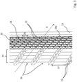
- FIG 2 shows a detail view of the outflow grating 20 of Figure 1 .
- the outflow grating 20 comprises a plurality of honeycomb-shaped grating openings 24, each of them bounded by six webs 22 arranged in a regular hexagon.
- Each of the webs 22 separates two adjacent grating openings 24 from each other.
- the webs 22 have two bevels 26 each, which extend at an angle to a main flow direction L. In the exemplary embodiment shown here, the webs 22 therefore have an approximately triangular cross section area. Because of the inclination of the bevels 26, the grating openings 24 widen in the main flow direction L.
- the end edges of the webs 22 have fillets 28.
- stiffening webs 23 can be seen in Figure 2 , which give a greater rigidity to the outflow grating 20.
- the outflow grating 20 affects the orienting of an air flow flowing through the outflow grating only slightly. Therefore, an air flow deviating from the main flow direction L is not forced back in the direction of the main flow direction, but instead can maintain its direction of flow and slide along in each case one of the six bevels 26 of the grating opening 24. This is especially recognizable in Figure 3 .
- Upstream from the outflow grating 20 are arranged air-guiding elements, in the present case five air-guiding gratings 32 as a common grating package 34.
- the air-guiding gratings 32 are displaced relative to each other such that an air flow directed along the arrow line designated G emerges from the air vent.
- This air flow G - directed downward in the example of Figure 3 - slides here in particular along the lower bevels 26a of the grating openings 24.
- a correspondingly oriented air flow in five further directions is also especially well maintained by means of the other five bevels.
- the fillets 28 at the end edges of the webs 22 also contribute to a better air guidance.
- the air flow G can follow the course of the fillets 28 at least for a bit, which prevents a hard flow detachment and thus swirling.
- the grating openings 36 of the air-guiding gratings 32 are larger than the grating openings 24 of the outflow grating 20.
- an opening width 37 of the grating openings 36 of the air-guiding grating 32 is larger than an opening width 25 of the grating openings 24 of the outflow grating 20.
- the outflow grating 20 has a substantially finer opening grid, which conceals the air-guiding gratings 32 located behind it as seen from the interior of the vehicle and thereby affords a visual cover. Despite the visual cover ensured by the outflow grating, a targeted deflection of the air flow can be achieved and maintained thanks to the upstream mounted air-guiding elements, especially also thanks to the discussed configuration of the outflow grating.
- FIG. 4 shows an air vent according to another embodiment in a partly sectioned perspective rear view.
- the air vent 10 of Figure 4 differs from the previously explained air vent only in that the housing 12 is two-piece.
- the housing 12 comprises a rear housing piece 12a and a front housing piece 12b, having the diaphragm.
- the air vent comprises an outflow grating 20 and a grating package 34 of air-guiding gratings 32, as in Fig. 3 .
- the air-guiding gratings 32 of the grating package 34 are slightly curved and rest with substantially no gaps against each other and against the outflow grating 20.
- a deflection of an air flow flowing through the air duct 18 occurs by a displacement of the air-guiding gratings 32 relative to each other.
- This displacement is accomplished in the present case by a first operating mechanism, comprising in particular the outflow grating 20, a connection element 42, a tilting bracket 60 as well as a synchronizing lever 62. This is illustrated in particular in Figure 5 .
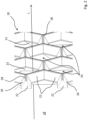
- FIG. 5 shows the grating package 34 together with outflow grating 20 and the elements of the operating mechanism from Figure 4 in an exploded view.
- the grating package 34 consists of five air-guiding gratings 32a - 32e.
- the air-guiding gratings 32a - 32e respectively form an opening grid with grating openings 36.
- the grating openings 36 are larger, in particular they have a larger opening width 37 than the grating openings 24 of the outflow grating 20.
- the outflow grating 20 thus conceals the grating package 34 as seen from the interior of a vehicle.
- connection element 42 has four cross braces 44 extending outwardly from a centrally situated slide guideway 46.
- the cross braces 44 each have fastening means 48 at their ends, which in the present instance are designed as receiving openings.
- the air-guiding grating 32a next to the outflow grating 20 has fastening means 49 corresponding to the fastening means 48, being designed in the present instance as pins.
- the air-guiding grating 32a has a tilting bracket mounting 61 at its upper end in Figure 5 , to which a tilting bracket 60 is secured.
- the tilting bracket 60 In the assembled state of the air-guiding gratings 32a - 32e, the tilting bracket 60 passes with its projecting ends 60a through the passageway openings 63 of the air-guiding gratings 32b to 32e. Fastening means 49 of the front air-guiding grating 32a pass through the corresponding fastening means 48 in the installed state.
- the connection element 42 holds a slide 50.
- the slide 50 has a longitudinal guide 52 arranged vertically along the axis V and a transverse runner 54 arranged horizontally along the axis H.
- the slide 50 is received by its transverse runner 54 in the slide guideway 46 of the connection element 42 and thus allows a movement of the connection element 42 relative to the slide 50 along the horizontal axis H.
- a longitudinal runner 56 of the air-guiding grating 32e furthest away from the outflow grating 20 is guided in the longitudinal guide 52.
- the inner air-guiding grating 32e is secured by two bearing elements 58 arranged at opposite sides to the housing 12 of the air vent, only showing one of the bearing elements in Figure 5 .
- the air-guiding grating 32e is thus stationary, i.e., it does not move upon adjustment of the other air-guiding gratings.
- the other air-guiding gratings 32a - 32d are adjusted synchronously relative to the air-guiding grating 32e.
- a synchronous adjustment of the air-guiding gratings 32a - 32d along the vertical axis V is ensured by the tilting bracket 60.
- a synchronous adjustment of the air-guiding gratings 32a - 32e along the horizontal axis H is made possible by a synchronizing lever 62.
- the outflow grating 22 is mounted on the outer air-guiding grating 32a, especially clipped thereon, and is thus rigidly connected to the outer air-guiding grating 32a.
- the synchronizing lever 62 comprises a swivel bearing 64 by which it is mounted on the middle air-guiding grating 32c.
- the swivel bearing 64 here reaches through a bearing opening 65 of the middle air-guiding grating 32c.
- the synchronizing lever 62 has four pegs 66, which extend in pairs in opposite directions away from the synchronizing lever 62 and contact slotted links 68 of the air-guiding gratings 32a and 32b or 32d and 32e.
- the pegs 66 of the synchronizing lever 62 as well as the slotted links 68 of the air-guiding gratings 32a and 32b or 32d and 32e form here a slotted link guide making possible a lateral displaceability of the air-guiding gratings along the horizontal axis H, as explained in the following.
- the outflow grating 20 in this embodiment serves therefore as an operating element, which can be displaced in a surface parallel to the areas of extent of the air-guiding gratings 32a - 32e. Since the outflow grating 20 is rigidly connected to the outer air-guiding grating 32a, a movement of the outflow grating 20 is also followed by a movement of the air-guiding grating 32a and thus of the connection element 42 connected to the air-guiding grating 32a at the rear.
- the other air-guiding gratings are also moved synchronously with the air-guiding grating 32a.
- the movement is braced here against the stationary inner air-guiding grating 32a, which results in a relative displacement of the air-guiding gratings with respect to each other.
- the connection element 42 thus slides via its slide guideway 46 along the transverse runner 54 of the slide 50.
- the slide 50 can indeed move along the vertical V, in which case it slides by means of the longitudinal guide 52 along the longitudinal runner 56 of the inner air-guiding grating 32e.
- the slide 50 cannot move here along the horizontal axis H on account of the engagement of its longitudinal guide 52 with the longitudinal runner 56 extending along the vertical V.
- the horizontal movement is represented in Figure 6 .
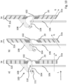
- Figure 6 shows the air vent of Figure 4 in three sectional views along the horizontal axis H, where the sectional views show the grating package 34 in different positions.
- Figure 6c shows the grating package 34 in a zero position, in which the grating openings 36 form a flow opening D extending along the main flow direction.
- the outflow grating 20 starting from the zero position is adjusted to the left along the horizontal axis.
- the connection element 42 has also been adjusted to the left along the horizontal axis, while the slide guideway 46 of the connection element 42 runs along the transverse runner 54 of the slide 50.
- the other air-guiding gratings are here adjusted relative to each other synchronously such that a through opening D pointing to the left is formed.
- connection element 42 by means of its slide guideway 46 along the transverse runner 54 can also be seen in particular in Figure 7 .
- Figure 7 shows the air vent from Fig. 4 looking along the main flow direction at the grating package 34 in three different positions of the grating package.
- the other inner situated air-guiding gratings 32d and 32e are not shown in Figure 7.
- Figure 7a shows the zero position of the grating package 34, in which no deflection of the air flow from the main flow direction L occurs.
- the synchronizing lever 62 is oriented substantially vertically along the axis V.
- the synchronizing lever 62 pivots about its swivel bearing 64 and thus is tilted with respect to the vertical V, in parallel with the planes of extension of the air-guiding gratings, as shown in Figures 7b and 7c .
- This tilting occurs because the synchronizing lever 62 is mounted by one of its pegs 66 in the stationary air-guiding grating 32e.
- the pegs 66 of the synchronizing lever 62 slide here in the slotted links 68 of the other air-guiding gratings 32a, b, d, e.
- the synchronizing lever 62 is tilted by a movement of the outflow grating 20 and consequently of the first air-guiding grating 32a, which in turn results in a synchronous movement of the other air-guiding gratings.
- the synchronizing lever thus synchronizes the movement of the air-guiding gratings along the horizontal axis H.
- a deflection of the air flow from the main flow direction along the vertical direction occurs by a displacement of the outflow grating in the corresponding direction, i.e., upward or downward as seen from the interior of a vehicle.
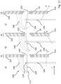
- This is represented in Figure 8 .
- the grating openings 36 of the air-guiding gratings 32 coincide, so that they form through openings D extending substantially along the main flow direction.
- the air flow G consequently flows substantially along the main flow direction.
- the outflow grating 20 is adjusted upward along the vertical V, as shown in Figure 8b , the outer air-guiding grating 32a and there with the connection element 42 likewise thus moves upward.
- the connection element 42 carries along the slide 50 here via its slide guideway 46.
- the longitudinal guide 52 slides here along the longitudinal runner 56 of the inner air-guiding grating 32e arranged firmly on the housing. Thanks to the coupling of the air-guiding gratings 32 via the tilting bracket 60 along the vertical axis V, there occurs a synchronous movement of the air-guiding gratings 32b - d relative to each other.
- the through openings D thus deflect the air flow G upward from the main flow direction.
- a downward movement of the outflow grating 20 along the vertical V results in a movement of the connection element 42 and consequently the nonstationary air-guiding gratings in the same direction.
- the slide 50 is led in this process by its longitudinal guide 52 on the longitudinal runner 56 of the inner air-guiding grating 32e mounted firmly on the housing. There thus occurs a downward deflection of the air flow G.
- a control wheel 40 which serves for the adjusting of a shut-off element mounted in the air duct upstream of the air-guiding elements, in order to throttle or entirely halt the air flow moving through the air duct.
- Figures 9 and 10 show another exemplary embodiment of an air vent according to the invention.
- This exemplary embodiment differs from the previous one in that the outflow grating 20 is stationary and has a central opening for the feedthrough of an operating element 102.
- the outflow grating 20 as well as the air-guiding gratings 32 of the grating package 34 are not curved, but rather are formed along parallel planes perpendicular to the main flow direction L.
- An operation of the air-guiding gratings situated behind the outflow grating 20 occurs by the operating element 102, which can be displaced along the arrows shown in a surface.
- the operating element 102 may be arranged on or at the outflow grating 20.
- the operating element 102 may be recessed in the outflow grating 20, as shown in Figure 10 .
- the operating element 102 in this case is designed as a plate, whose area is smaller than the outflow grating 20 and extends parallel thereto, as well as to the air-guiding gratings 32.
- Figure 10 shows an operating mechanism 100 which comprises, besides the operating element 102, a transmission element 104 coupled to the operating element 102.
- the transmission element 104 extends through a central opening of the grating package 34 through all the air-guiding gratings 32 into the air duct 18.
- Via a first bearing 110 the transmission element 104 is connected to a stationary component 106 fixed to the housing and via a second bearing 111 is connected to a transmission arm 108 in a swiveling manner along the horizontal axis H and along the vertical axis V.
- the bearings 110, 111 may be ball joints in particular, wherein the front ball joint 110 and the rear ball joint 111 also enable a movement of the transmission element 104 along its longitudinal axis.
- the transmission arm 108 is connected to the furthest inward situated air-guiding grating 32e, which in this exemplary embodiment is not mounted stationary on the housing. Instead, in the present instance, as mentioned, the outflow grating 20 is stationary.
- the inner air-guiding grating 32e is moved accordingly via the transmission element 104 and the transmission arm 108.
- the transmission element 104 moves substantially within a spherical segment in this case.
- the transmission element 104 moves relative to the bearings 110, 111 along its longitudinal axis, i.e., it moves out from or into the bearings 110, 111 for a bit.
- the outflow grating itself does not serve as the operating element for adjusting the air-guiding gratings. Instead, a separate operating element is provided. A synchronizing of the air-guiding gratings can occur in the manner described above.
- the exemplary embodiment in Figure 11 differs from that of Figures 9 and 10 by a different configuration of the operating element 102' as well as by a different bearing 111'.
- the operating element 102' is not configured as a plate, but instead as an end-side thickening of the transmission element 104.
- the operating element 102' here forms a prolongation of the transmission element 104 and is movable together with the transmission element 104 along a spherical surface, similar to a joystick.
- the transmission element 104 also moves here within a spherical segment, but - unlike in the previous exemplary embodiment - the rear ball joint 111' not being allowed any movement of the transmission element 104 along its longitudinal axis. Only the front ball joint 110 allows such an axial displacement of the transmission element.
- the transmission element 104 consequently moves within a spherical segment of a sphere whose center point lies at the ball joint 111'.
- FIGS 12 to 15 show an air vent according to another exemplary embodiment. Unlike the first exemplary embodiment, this air vent has no grating package made up of a plurality of air-guiding gratings, but instead has slats 200, 202 as the air-guiding elements.
- the outflow grating 20 in this embodiment is stationary, the slats being adjusted by separate operating elements, as explained below.
- Several horizontally disposed slats 200 for the deflection of the air flow from the main flow direction L in the vertical direction V can be seen here.
- An adjustment of the horizontal slats 200 occurs by a control wheel 204, which is connected by a tongue - and - groove connection 205 to one of the horizontal slats 200.
- the horizontal slats 200 are connected to each other, so that a movement of the control wheel 204 results in a synchronous movement of the slats 200.
- the vertical slats 202 extending along the vertical axis V are coupled together and can be tilted by a control wheel 206 with respect to the main flow direction.
- Figure 12 shows only one of the vertical slats 202 schematically. A deflection of the air flow G from the main flow direction L upward or downward along the vertical axis V occurs, as can be seen from Figure 14 and 15 , by corresponding tilting of the slats 200. A deflection along the horizontal axis to the sides can be done by adjusting the vertical slats 202.
- the opening grid of the air-guiding elements is formed on the one hand by the mutual spacings of the horizontal slats 200. Consequently, the grating openings 210 are defined here by the spacings between the horizontal slats 200. Also in this embodiment the air-guiding elements 200 form an opening grid with grating openings 210 which are larger than the grating openings 24 of the outflow grating 20. In particular, an opening width 212 of the grating openings of the slats 200 is larger than an opening width 25 of the grating openings 36 of the outflow grating 20. Correspondingly, the vertical slats 202 also form an opening grid with grating openings by the spacings existing therebetween.
Landscapes
- Physics & Mathematics (AREA)
- Thermal Sciences (AREA)
- Engineering & Computer Science (AREA)
- Mechanical Engineering (AREA)
- Air-Flow Control Members (AREA)
- Air-Conditioning For Vehicles (AREA)
Claims (13)
- Luftausströmer (10) für ein Fahrzeug, der Folgendes aufweist:- ein Gehäuse (12),- einen durch das Gehäuse (12) begrenzten Luftkanal (18), welcher ein Lufteinlassende (14) und ein Luftauslassende (16) hat, wobei ein durch den Luftkanal (18) strömender Luftstrom (G) von dem Lufteinlassende (14) zu dem Luftauslassende (16) entlang einer Hauptströmungsrichtung (L) strömen kann,- ein an dem Luftauslassende (16) angeordnetes Ausströmgitter (20), wobei das Ausströmgitter (20) ein Öffnungsgitter mit Gitteröffnungen (24) aufweist, die mittels Stegen (22) voneinander beabstandet sind, und- eine Vielzahl von Luftleitelementen (32, 200, 202), die in dem Luftkanal (18) in Strömungsrichtung (L) stromaufwärts des Ausströmgitters (20) ausgebildet sind, wobei die Luftleitelemente (32, 200, 202) ein Öffnungsgitter mit Gitteröffnungen (36, 210) ausbilden, die größer sind als die Gitteröffnungen (24) des Ausströmgitters (20),dadurch gekennzeichnet,dass die Gitteröffnungen (24) des Ausströmgitters (20) sich in der Hauptströmungsrichtung (L) erweitern, undwobei die Gitteröffnungen (24) desAusströmgitters (20)jeweils eine Öffnungsfläche im Bereich von 1 mm2 bis 25 mm2 aufweisen.
- Luftausströmer (10) nach Anspruch 1,
wobei die Gitteröffnungen (24) des Ausströmgitters (20) wabenförmig sind. - Luftausströmer (10) nach Anspruch 1 oder 2,
wobei das Ausströmgitter (20) auf seiner den Luftleitelementen (32, 200, 202) zugewandten Innenseite Verstärkungen (23) aufweist. - Luftausströmer (10) nach einem der vorhergehenden Ansprüche, wobei die Stege (22) des Ausströmgitters (20) an ihren von den Luftleitelementen (32, 200, 202) abgewandten Enden jeweils eine abgerundete Form aufweisen.
- Luftausströmer (10) nach einem der vorhergehenden Ansprüche, wobei die vorgesehenen Luftleitelemente schwenkbar gelagerte Lamellen (200, 202) sind, die sich senkrecht zu der Hauptströmungsrichtung (L) erstrecken.
- Luftausströmer (10) nach einem der Ansprüche 1 bis 4,
wobei die vorgesehenen Luftleitelemente Luftleitgitter (32) sind, die sich im Wesentlichen senkrecht zu der Hauptströmungsrichtung (L) erstrecken und ein Gitterpaket (34) ausbilden. - Luftausströmer (10) nach Anspruch 6,
wobei ein Synchronisationsmechanismus vorgesehen ist, mittels dessen eine parallele Verschiebung der Luftleitgitter (32) synchronisiert wird. - Luftausströmer (10) nach Anspruch 7,
wobei der Synchronisationsmechanismus zumindest einen Synchronisationshebel (62) aufweist, der mit den Luftleitgittern (32) gekoppelt ist. - Luftausströmer (10) nach Anspruch 8,
wobei die Luftleitgitter (32) mittels einer geschlitzten Verbindungsführung (66, 68) mit dem Synchronisationshebel (62) gekoppelt sind. - Luftausströmer (10) nach einem der Ansprüche 7 bis 9,
wobei ein inneres Luftleitgitter (32e) fest ist und die verbleibenden Luftleitgitter synchron verstellt werden, oder dass ein äußeres Luftleitgitter (32a) fest ist und die verbleibenden Luftleitgitter synchron verstellt werden. - Luftausströmer (10) nach einem der Ansprüche 7 bis 10, wobei der Luftausströmer (10) ein Bedienelement (20, 102) zum Verstellen der Luftleitgitter (32) aufweist, wobei das Bedienelement (20, 102) in einem Bereich verschiebbar ist, der sich parallel zu einer Erstreckungsfläche zumindest eines der Luftleitgitter (32) erstreckt.
- Luftausströmer (10) nach Anspruch 11,
wobei das Ausströmgitter (20) das Bedienelement ausbildet. - Luftausströmer (10) nach einem der Ansprüche 7 bis 10, wobei an dem Ausströmgitter (20) ein Bedienelement (102) angeordnet ist, wobei sich ein mit dem Bedienelement (102) wirkverbundenes Übertragungselement (104) durch das Ausströmgitter (20) und das Gitterpaket (34) erstreckt, an einer ortsfesten Komponente (106) innerhalb des Luftkanals (18) abgestützt ist und auf ein inneres Luftleitgitter (32e) wirkt.
Applications Claiming Priority (1)
| Application Number | Priority Date | Filing Date | Title |
|---|---|---|---|
| DE102017118450.3A DE102017118450A1 (de) | 2017-08-14 | 2017-08-14 | Luftausströmer für ein Fahrzeug |
Publications (2)
| Publication Number | Publication Date |
|---|---|
| EP3444136A1 EP3444136A1 (de) | 2019-02-20 |
| EP3444136B1 true EP3444136B1 (de) | 2023-09-06 |
Family
ID=63047199
Family Applications (1)
| Application Number | Title | Priority Date | Filing Date |
|---|---|---|---|
| EP18185459.7A Active EP3444136B1 (de) | 2017-08-14 | 2018-07-25 | Luftausströmer für ein fahrzeug |
Country Status (5)
| Country | Link |
|---|---|
| US (1) | US20190047376A1 (de) |
| EP (1) | EP3444136B1 (de) |
| KR (1) | KR20190018394A (de) |
| CN (1) | CN109383237A (de) |
| DE (1) | DE102017118450A1 (de) |
Families Citing this family (11)
| Publication number | Priority date | Publication date | Assignee | Title |
|---|---|---|---|---|
| DE102018104043A1 (de) | 2018-02-22 | 2019-08-22 | Illinois Tool Works Inc. | Luftausströmer für ein Fahrzeug |
| US11958339B2 (en) * | 2018-03-13 | 2024-04-16 | Mahindra & Mahindra Limited | Concealed air vent apparatus in vehicle and a method thereof |
| EP3670223B1 (de) * | 2018-12-21 | 2022-06-29 | Valeo Autosystemy SP. Z.O.O. | Heizung-, lüftungs- und klimatisierungssystem |
| DE102019106086B4 (de) * | 2019-03-11 | 2023-06-22 | GRAMMER Interior Components GmbH | Luftausströmer für den Innenraum eines Kraftfahrzeuges |
| DE102019118239A1 (de) | 2019-07-05 | 2021-01-07 | Fischer Automotive Systems Gmbh & Co. Kg | Luftausströmer |
| CA196846S (en) | 2020-01-14 | 2022-02-14 | Blueair Ab | Air purifier |
| KR102412025B1 (ko) * | 2020-02-05 | 2022-06-21 | 일리노이즈 툴 워크스 인코포레이티드 | 차량용 에어 벤트 |
| DE102020103630B4 (de) | 2020-02-12 | 2023-12-21 | Audi Aktiengesellschaft | Luftausströmvorrichtung für ein Fahrzeug |
| USD993373S1 (en) * | 2020-07-13 | 2023-07-25 | Blueair Ab | Air intake for an air purifier |
| KR102907535B1 (ko) | 2021-01-18 | 2026-01-05 | 현대모비스 주식회사 | 차량용 메쉬형 에어벤트 장치 |
| KR20220114995A (ko) | 2021-02-09 | 2022-08-17 | 현대모비스 주식회사 | 직간접 다기능을 갖춘 차량의 에어벤트 장치 |
Family Cites Families (10)
| Publication number | Priority date | Publication date | Assignee | Title |
|---|---|---|---|---|
| US4653385A (en) * | 1984-09-20 | 1987-03-31 | Toyoda Gosei Co., Ltd. | Air intake grille |
| DE19648736C1 (de) * | 1996-11-25 | 1998-01-15 | Daimler Benz Ag | Belüftungsdüse |
| US6159092A (en) * | 1998-08-31 | 2000-12-12 | Fickenscher America, L.L.C. | Air vent having two coplanar vane sets |
| SE519450C2 (sv) * | 1999-12-29 | 2003-03-04 | Volvo Personvagnar Ab | Anordning för att minska reflexer och kontraster vid ventilationsmunstycken |
| JP3879655B2 (ja) * | 2002-11-06 | 2007-02-14 | 株式会社デンソー | 車両空調用天井吹出装置 |
| DE102006009577A1 (de) * | 2006-02-28 | 2007-09-06 | Behr Gmbh & Co. Kg | Kraftfahrzeug-Belüftungssystem |
| EP2046591A4 (de) * | 2006-07-27 | 2010-04-21 | Collins & Aikman Prod Co | Diffusionsluftauslass |
| KR101479369B1 (ko) * | 2007-09-21 | 2015-01-05 | 에어그린 엘티디. | 공조 시스템들로부터 공기 제트를 방출하고 주위 공기를 혼합시키는 장치 |
| JP5529564B2 (ja) * | 2010-01-29 | 2014-06-25 | 豊和化成株式会社 | レジスタ |
| JP2014043220A (ja) * | 2012-08-28 | 2014-03-13 | Marusan Kinzoku:Kk | 風向調節羽根及び空気吹出口 |
-
2017
- 2017-08-14 DE DE102017118450.3A patent/DE102017118450A1/de active Pending
-
2018
- 2018-07-25 EP EP18185459.7A patent/EP3444136B1/de active Active
- 2018-08-08 US US16/057,977 patent/US20190047376A1/en not_active Abandoned
- 2018-08-09 CN CN201810902317.2A patent/CN109383237A/zh active Pending
- 2018-08-13 KR KR1020180094415A patent/KR20190018394A/ko not_active Withdrawn
Also Published As
| Publication number | Publication date |
|---|---|
| KR20190018394A (ko) | 2019-02-22 |
| US20190047376A1 (en) | 2019-02-14 |
| CN109383237A (zh) | 2019-02-26 |
| DE102017118450A1 (de) | 2019-02-14 |
| EP3444136A1 (de) | 2019-02-20 |
Similar Documents
| Publication | Publication Date | Title |
|---|---|---|
| EP3444136A1 (de) | Luftausströmer für ein fahrzeug | |
| US20160250909A1 (en) | Air nozzle | |
| EP1655161B1 (de) | Belüftungsdüse für Lüftungssysteme | |
| KR101160865B1 (ko) | 공조 장치의 취출구 구조 | |
| EP2777966B1 (de) | Register | |
| US12296652B2 (en) | Air vent for a vehicle | |
| EP3590744B1 (de) | Einstellbarer luftausströmer | |
| CN101213101A (zh) | 空气出口喷嘴 | |
| US11285786B2 (en) | Outlet device | |
| CN107672419B (zh) | 出风口总成及组装出风口系统的方法 | |
| CN108025620B (zh) | 用于将空气导入车辆的乘客车厢中的布置系统和方法 | |
| EP3398798A1 (de) | Entlüftung zur verwendung in einem fahrzeug | |
| EP3492831A1 (de) | Register | |
| JP2011136683A (ja) | 車両の換気システム | |
| CN106796048A (zh) | 通风装置 | |
| WO2018074022A1 (ja) | 空調装置の吹出装置 | |
| JP3215056U (ja) | レジスタ | |
| EP3173269B1 (de) | Innenraumlüfter für ein fahrzeug und verfahren zur montage eines innenraumlüfters | |
| EP3817934B1 (de) | Luftausströmer für ein fahrzeug | |
| JP2018203088A (ja) | レジスタ | |
| JP2020069961A (ja) | 風向調整装置 | |
| KR20200117485A (ko) | 차량의 실내 장식 구조 | |
| DE102011003432A1 (de) | Ausströmer für ein Belüftungssystem eines Fahrzeugs | |
| EP3626493B1 (de) | Luftausströmer für ein fahrzeug | |
| US11180002B2 (en) | Air vents for vehicle interior |
Legal Events
| Date | Code | Title | Description |
|---|---|---|---|
| PUAI | Public reference made under article 153(3) epc to a published international application that has entered the european phase |
Free format text: ORIGINAL CODE: 0009012 |
|
| STAA | Information on the status of an ep patent application or granted ep patent |
Free format text: STATUS: THE APPLICATION HAS BEEN PUBLISHED |
|
| AK | Designated contracting states |
Kind code of ref document: A1 Designated state(s): AL AT BE BG CH CY CZ DE DK EE ES FI FR GB GR HR HU IE IS IT LI LT LU LV MC MK MT NL NO PL PT RO RS SE SI SK SM TR |
|
| AX | Request for extension of the european patent |
Extension state: BA ME |
|
| STAA | Information on the status of an ep patent application or granted ep patent |
Free format text: STATUS: REQUEST FOR EXAMINATION WAS MADE |
|
| 17P | Request for examination filed |
Effective date: 20190819 |
|
| RBV | Designated contracting states (corrected) |
Designated state(s): AL AT BE BG CH CY CZ DE DK EE ES FI FR GB GR HR HU IE IS IT LI LT LU LV MC MK MT NL NO PL PT RO RS SE SI SK SM TR |
|
| STAA | Information on the status of an ep patent application or granted ep patent |
Free format text: STATUS: EXAMINATION IS IN PROGRESS |
|
| 17Q | First examination report despatched |
Effective date: 20210216 |
|
| GRAP | Despatch of communication of intention to grant a patent |
Free format text: ORIGINAL CODE: EPIDOSNIGR1 |
|
| STAA | Information on the status of an ep patent application or granted ep patent |
Free format text: STATUS: GRANT OF PATENT IS INTENDED |
|
| RIC1 | Information provided on ipc code assigned before grant |
Ipc: B60H 1/34 20060101AFI20230130BHEP |
|
| INTG | Intention to grant announced |
Effective date: 20230306 |
|
| GRAS | Grant fee paid |
Free format text: ORIGINAL CODE: EPIDOSNIGR3 |
|
| P01 | Opt-out of the competence of the unified patent court (upc) registered |
Effective date: 20230606 |
|
| GRAA | (expected) grant |
Free format text: ORIGINAL CODE: 0009210 |
|
| STAA | Information on the status of an ep patent application or granted ep patent |
Free format text: STATUS: THE PATENT HAS BEEN GRANTED |
|
| AK | Designated contracting states |
Kind code of ref document: B1 Designated state(s): AL AT BE BG CH CY CZ DE DK EE ES FI FR GB GR HR HU IE IS IT LI LT LU LV MC MK MT NL NO PL PT RO RS SE SI SK SM TR |
|
| REG | Reference to a national code |
Ref country code: GB Ref legal event code: FG4D |
|
| REG | Reference to a national code |
Ref country code: CH Ref legal event code: EP |
|
| REG | Reference to a national code |
Ref country code: IE Ref legal event code: FG4D |
|
| REG | Reference to a national code |
Ref country code: DE Ref legal event code: R096 Ref document number: 602018056858 Country of ref document: DE |
|
| REG | Reference to a national code |
Ref country code: LT Ref legal event code: MG9D |
|
| REG | Reference to a national code |
Ref country code: NL Ref legal event code: MP Effective date: 20230906 |
|
| PG25 | Lapsed in a contracting state [announced via postgrant information from national office to epo] |
Ref country code: GR Free format text: LAPSE BECAUSE OF FAILURE TO SUBMIT A TRANSLATION OF THE DESCRIPTION OR TO PAY THE FEE WITHIN THE PRESCRIBED TIME-LIMIT Effective date: 20231207 |
|
| PG25 | Lapsed in a contracting state [announced via postgrant information from national office to epo] |
Ref country code: SE Free format text: LAPSE BECAUSE OF FAILURE TO SUBMIT A TRANSLATION OF THE DESCRIPTION OR TO PAY THE FEE WITHIN THE PRESCRIBED TIME-LIMIT Effective date: 20230906 Ref country code: RS Free format text: LAPSE BECAUSE OF FAILURE TO SUBMIT A TRANSLATION OF THE DESCRIPTION OR TO PAY THE FEE WITHIN THE PRESCRIBED TIME-LIMIT Effective date: 20230906 Ref country code: NO Free format text: LAPSE BECAUSE OF FAILURE TO SUBMIT A TRANSLATION OF THE DESCRIPTION OR TO PAY THE FEE WITHIN THE PRESCRIBED TIME-LIMIT Effective date: 20231206 Ref country code: LV Free format text: LAPSE BECAUSE OF FAILURE TO SUBMIT A TRANSLATION OF THE DESCRIPTION OR TO PAY THE FEE WITHIN THE PRESCRIBED TIME-LIMIT Effective date: 20230906 Ref country code: LT Free format text: LAPSE BECAUSE OF FAILURE TO SUBMIT A TRANSLATION OF THE DESCRIPTION OR TO PAY THE FEE WITHIN THE PRESCRIBED TIME-LIMIT Effective date: 20230906 Ref country code: HR Free format text: LAPSE BECAUSE OF FAILURE TO SUBMIT A TRANSLATION OF THE DESCRIPTION OR TO PAY THE FEE WITHIN THE PRESCRIBED TIME-LIMIT Effective date: 20230906 Ref country code: GR Free format text: LAPSE BECAUSE OF FAILURE TO SUBMIT A TRANSLATION OF THE DESCRIPTION OR TO PAY THE FEE WITHIN THE PRESCRIBED TIME-LIMIT Effective date: 20231207 Ref country code: FI Free format text: LAPSE BECAUSE OF FAILURE TO SUBMIT A TRANSLATION OF THE DESCRIPTION OR TO PAY THE FEE WITHIN THE PRESCRIBED TIME-LIMIT Effective date: 20230906 |
|
| REG | Reference to a national code |
Ref country code: AT Ref legal event code: MK05 Ref document number: 1608089 Country of ref document: AT Kind code of ref document: T Effective date: 20230906 |
|
| PG25 | Lapsed in a contracting state [announced via postgrant information from national office to epo] |
Ref country code: NL Free format text: LAPSE BECAUSE OF FAILURE TO SUBMIT A TRANSLATION OF THE DESCRIPTION OR TO PAY THE FEE WITHIN THE PRESCRIBED TIME-LIMIT Effective date: 20230906 |
|
| PG25 | Lapsed in a contracting state [announced via postgrant information from national office to epo] |
Ref country code: IS Free format text: LAPSE BECAUSE OF FAILURE TO SUBMIT A TRANSLATION OF THE DESCRIPTION OR TO PAY THE FEE WITHIN THE PRESCRIBED TIME-LIMIT Effective date: 20240106 |
|
| PG25 | Lapsed in a contracting state [announced via postgrant information from national office to epo] |
Ref country code: AT Free format text: LAPSE BECAUSE OF FAILURE TO SUBMIT A TRANSLATION OF THE DESCRIPTION OR TO PAY THE FEE WITHIN THE PRESCRIBED TIME-LIMIT Effective date: 20230906 |
|
| PG25 | Lapsed in a contracting state [announced via postgrant information from national office to epo] |
Ref country code: ES Free format text: LAPSE BECAUSE OF FAILURE TO SUBMIT A TRANSLATION OF THE DESCRIPTION OR TO PAY THE FEE WITHIN THE PRESCRIBED TIME-LIMIT Effective date: 20230906 |
|
| PG25 | Lapsed in a contracting state [announced via postgrant information from national office to epo] |
Ref country code: SM Free format text: LAPSE BECAUSE OF FAILURE TO SUBMIT A TRANSLATION OF THE DESCRIPTION OR TO PAY THE FEE WITHIN THE PRESCRIBED TIME-LIMIT Effective date: 20230906 Ref country code: RO Free format text: LAPSE BECAUSE OF FAILURE TO SUBMIT A TRANSLATION OF THE DESCRIPTION OR TO PAY THE FEE WITHIN THE PRESCRIBED TIME-LIMIT Effective date: 20230906 Ref country code: IS Free format text: LAPSE BECAUSE OF FAILURE TO SUBMIT A TRANSLATION OF THE DESCRIPTION OR TO PAY THE FEE WITHIN THE PRESCRIBED TIME-LIMIT Effective date: 20240106 Ref country code: ES Free format text: LAPSE BECAUSE OF FAILURE TO SUBMIT A TRANSLATION OF THE DESCRIPTION OR TO PAY THE FEE WITHIN THE PRESCRIBED TIME-LIMIT Effective date: 20230906 Ref country code: EE Free format text: LAPSE BECAUSE OF FAILURE TO SUBMIT A TRANSLATION OF THE DESCRIPTION OR TO PAY THE FEE WITHIN THE PRESCRIBED TIME-LIMIT Effective date: 20230906 Ref country code: CZ Free format text: LAPSE BECAUSE OF FAILURE TO SUBMIT A TRANSLATION OF THE DESCRIPTION OR TO PAY THE FEE WITHIN THE PRESCRIBED TIME-LIMIT Effective date: 20230906 Ref country code: AT Free format text: LAPSE BECAUSE OF FAILURE TO SUBMIT A TRANSLATION OF THE DESCRIPTION OR TO PAY THE FEE WITHIN THE PRESCRIBED TIME-LIMIT Effective date: 20230906 Ref country code: SK Free format text: LAPSE BECAUSE OF FAILURE TO SUBMIT A TRANSLATION OF THE DESCRIPTION OR TO PAY THE FEE WITHIN THE PRESCRIBED TIME-LIMIT Effective date: 20230906 Ref country code: PT Free format text: LAPSE BECAUSE OF FAILURE TO SUBMIT A TRANSLATION OF THE DESCRIPTION OR TO PAY THE FEE WITHIN THE PRESCRIBED TIME-LIMIT Effective date: 20240108 |
|
| PG25 | Lapsed in a contracting state [announced via postgrant information from national office to epo] |
Ref country code: PL Free format text: LAPSE BECAUSE OF FAILURE TO SUBMIT A TRANSLATION OF THE DESCRIPTION OR TO PAY THE FEE WITHIN THE PRESCRIBED TIME-LIMIT Effective date: 20230906 Ref country code: IT Free format text: LAPSE BECAUSE OF FAILURE TO SUBMIT A TRANSLATION OF THE DESCRIPTION OR TO PAY THE FEE WITHIN THE PRESCRIBED TIME-LIMIT Effective date: 20230906 |
|
| REG | Reference to a national code |
Ref country code: DE Ref legal event code: R097 Ref document number: 602018056858 Country of ref document: DE |
|
| PG25 | Lapsed in a contracting state [announced via postgrant information from national office to epo] |
Ref country code: DK Free format text: LAPSE BECAUSE OF FAILURE TO SUBMIT A TRANSLATION OF THE DESCRIPTION OR TO PAY THE FEE WITHIN THE PRESCRIBED TIME-LIMIT Effective date: 20230906 |
|
| PLBE | No opposition filed within time limit |
Free format text: ORIGINAL CODE: 0009261 |
|
| STAA | Information on the status of an ep patent application or granted ep patent |
Free format text: STATUS: NO OPPOSITION FILED WITHIN TIME LIMIT |
|
| PG25 | Lapsed in a contracting state [announced via postgrant information from national office to epo] |
Ref country code: DK Free format text: LAPSE BECAUSE OF FAILURE TO SUBMIT A TRANSLATION OF THE DESCRIPTION OR TO PAY THE FEE WITHIN THE PRESCRIBED TIME-LIMIT Effective date: 20230906 Ref country code: SI Free format text: LAPSE BECAUSE OF FAILURE TO SUBMIT A TRANSLATION OF THE DESCRIPTION OR TO PAY THE FEE WITHIN THE PRESCRIBED TIME-LIMIT Effective date: 20230906 |
|
| 26N | No opposition filed |
Effective date: 20240607 |
|
| PG25 | Lapsed in a contracting state [announced via postgrant information from national office to epo] |
Ref country code: BG Free format text: LAPSE BECAUSE OF FAILURE TO SUBMIT A TRANSLATION OF THE DESCRIPTION OR TO PAY THE FEE WITHIN THE PRESCRIBED TIME-LIMIT Effective date: 20230906 |
|
| PG25 | Lapsed in a contracting state [announced via postgrant information from national office to epo] |
Ref country code: BG Free format text: LAPSE BECAUSE OF FAILURE TO SUBMIT A TRANSLATION OF THE DESCRIPTION OR TO PAY THE FEE WITHIN THE PRESCRIBED TIME-LIMIT Effective date: 20230906 |
|
| PG25 | Lapsed in a contracting state [announced via postgrant information from national office to epo] |
Ref country code: MC Free format text: LAPSE BECAUSE OF FAILURE TO SUBMIT A TRANSLATION OF THE DESCRIPTION OR TO PAY THE FEE WITHIN THE PRESCRIBED TIME-LIMIT Effective date: 20230906 |
|
| REG | Reference to a national code |
Ref country code: CH Ref legal event code: PL |
|
| PG25 | Lapsed in a contracting state [announced via postgrant information from national office to epo] |
Ref country code: LU Free format text: LAPSE BECAUSE OF NON-PAYMENT OF DUE FEES Effective date: 20240725 |
|
| GBPC | Gb: european patent ceased through non-payment of renewal fee |
Effective date: 20240725 |
|
| PG25 | Lapsed in a contracting state [announced via postgrant information from national office to epo] |
Ref country code: LU Free format text: LAPSE BECAUSE OF NON-PAYMENT OF DUE FEES Effective date: 20240725 |
|
| PG25 | Lapsed in a contracting state [announced via postgrant information from national office to epo] |
Ref country code: CH Free format text: LAPSE BECAUSE OF NON-PAYMENT OF DUE FEES Effective date: 20240731 Ref country code: BE Free format text: LAPSE BECAUSE OF NON-PAYMENT OF DUE FEES Effective date: 20240731 |
|
| PG25 | Lapsed in a contracting state [announced via postgrant information from national office to epo] |
Ref country code: FR Free format text: LAPSE BECAUSE OF NON-PAYMENT OF DUE FEES Effective date: 20240731 |
|
| PG25 | Lapsed in a contracting state [announced via postgrant information from national office to epo] |
Ref country code: GB Free format text: LAPSE BECAUSE OF NON-PAYMENT OF DUE FEES Effective date: 20240725 |
|
| REG | Reference to a national code |
Ref country code: BE Ref legal event code: MM Effective date: 20240731 |
|
| PG25 | Lapsed in a contracting state [announced via postgrant information from national office to epo] |
Ref country code: IE Free format text: LAPSE BECAUSE OF NON-PAYMENT OF DUE FEES Effective date: 20240725 |
|
| PGFP | Annual fee paid to national office [announced via postgrant information from national office to epo] |
Ref country code: DE Payment date: 20250729 Year of fee payment: 8 |
|
| PG25 | Lapsed in a contracting state [announced via postgrant information from national office to epo] |
Ref country code: CY Free format text: LAPSE BECAUSE OF FAILURE TO SUBMIT A TRANSLATION OF THE DESCRIPTION OR TO PAY THE FEE WITHIN THE PRESCRIBED TIME-LIMIT; INVALID AB INITIO Effective date: 20180725 |
|
| PG25 | Lapsed in a contracting state [announced via postgrant information from national office to epo] |
Ref country code: HU Free format text: LAPSE BECAUSE OF FAILURE TO SUBMIT A TRANSLATION OF THE DESCRIPTION OR TO PAY THE FEE WITHIN THE PRESCRIBED TIME-LIMIT; INVALID AB INITIO Effective date: 20180725 |