EP3442485B1 - Klebebandanordnungen - Google Patents
Klebebandanordnungen Download PDFInfo
- Publication number
- EP3442485B1 EP3442485B1 EP17719132.7A EP17719132A EP3442485B1 EP 3442485 B1 EP3442485 B1 EP 3442485B1 EP 17719132 A EP17719132 A EP 17719132A EP 3442485 B1 EP3442485 B1 EP 3442485B1
- Authority
- EP
- European Patent Office
- Prior art keywords
- component
- edge
- extension
- bonding
- fastening
- Prior art date
- Legal status (The legal status is an assumption and is not a legal conclusion. Google has not performed a legal analysis and makes no representation as to the accuracy of the status listed.)
- Active
Links
- 230000000712 assembly Effects 0.000 title description 29
- 238000000429 assembly Methods 0.000 title description 29
- 239000002390 adhesive tape Substances 0.000 title description 2
- 239000000853 adhesive Substances 0.000 claims description 40
- 230000001070 adhesive effect Effects 0.000 claims description 40
- 239000000758 substrate Substances 0.000 claims description 8
- -1 polypropylene Polymers 0.000 claims description 5
- 239000004743 Polypropylene Substances 0.000 claims description 3
- 229920001155 polypropylene Polymers 0.000 claims description 3
- 239000004698 Polyethylene Substances 0.000 claims description 2
- 229920000573 polyethylene Polymers 0.000 claims description 2
- 239000000463 material Substances 0.000 description 12
- 230000032798 delamination Effects 0.000 description 3
- 238000012549 training Methods 0.000 description 3
- VSKJLJHPAFKHBX-UHFFFAOYSA-N 2-methylbuta-1,3-diene;styrene Chemical compound CC(=C)C=C.C=CC1=CC=CC=C1.C=CC1=CC=CC=C1 VSKJLJHPAFKHBX-UHFFFAOYSA-N 0.000 description 2
- FACXGONDLDSNOE-UHFFFAOYSA-N buta-1,3-diene;styrene Chemical compound C=CC=C.C=CC1=CC=CC=C1.C=CC1=CC=CC=C1 FACXGONDLDSNOE-UHFFFAOYSA-N 0.000 description 2
- 239000007788 liquid Substances 0.000 description 2
- 238000004519 manufacturing process Methods 0.000 description 2
- 229920000468 styrene butadiene styrene block copolymer Polymers 0.000 description 2
- 239000002699 waste material Substances 0.000 description 2
- 206010021639 Incontinence Diseases 0.000 description 1
- 230000002745 absorbent Effects 0.000 description 1
- 239000002250 absorbent Substances 0.000 description 1
- 238000013459 approach Methods 0.000 description 1
- 238000010276 construction Methods 0.000 description 1
- 229920001577 copolymer Polymers 0.000 description 1
- 238000011161 development Methods 0.000 description 1
- 229920001971 elastomer Polymers 0.000 description 1
- 238000005516 engineering process Methods 0.000 description 1
- 238000003780 insertion Methods 0.000 description 1
- 230000037431 insertion Effects 0.000 description 1
- 238000000034 method Methods 0.000 description 1
- 238000012986 modification Methods 0.000 description 1
- 230000004048 modification Effects 0.000 description 1
- 230000001737 promoting effect Effects 0.000 description 1
- 239000005060 rubber Substances 0.000 description 1
- 239000011115 styrene butadiene Substances 0.000 description 1
Images
Classifications
-
- A—HUMAN NECESSITIES
- A61—MEDICAL OR VETERINARY SCIENCE; HYGIENE
- A61F—FILTERS IMPLANTABLE INTO BLOOD VESSELS; PROSTHESES; DEVICES PROVIDING PATENCY TO, OR PREVENTING COLLAPSING OF, TUBULAR STRUCTURES OF THE BODY, e.g. STENTS; ORTHOPAEDIC, NURSING OR CONTRACEPTIVE DEVICES; FOMENTATION; TREATMENT OR PROTECTION OF EYES OR EARS; BANDAGES, DRESSINGS OR ABSORBENT PADS; FIRST-AID KITS
- A61F13/00—Bandages or dressings; Absorbent pads
- A61F13/15—Absorbent pads, e.g. sanitary towels, swabs or tampons for external or internal application to the body; Supporting or fastening means therefor; Tampon applicators
- A61F13/56—Supporting or fastening means
- A61F13/58—Adhesive tab fastener elements
-
- A—HUMAN NECESSITIES
- A61—MEDICAL OR VETERINARY SCIENCE; HYGIENE
- A61F—FILTERS IMPLANTABLE INTO BLOOD VESSELS; PROSTHESES; DEVICES PROVIDING PATENCY TO, OR PREVENTING COLLAPSING OF, TUBULAR STRUCTURES OF THE BODY, e.g. STENTS; ORTHOPAEDIC, NURSING OR CONTRACEPTIVE DEVICES; FOMENTATION; TREATMENT OR PROTECTION OF EYES OR EARS; BANDAGES, DRESSINGS OR ABSORBENT PADS; FIRST-AID KITS
- A61F13/00—Bandages or dressings; Absorbent pads
- A61F13/15—Absorbent pads, e.g. sanitary towels, swabs or tampons for external or internal application to the body; Supporting or fastening means therefor; Tampon applicators
- A61F13/551—Packaging before or after use
- A61F13/55105—Packaging before or after use packaging of diapers
- A61F13/5512—Packaging before or after use packaging of diapers after use
-
- A—HUMAN NECESSITIES
- A61—MEDICAL OR VETERINARY SCIENCE; HYGIENE
- A61F—FILTERS IMPLANTABLE INTO BLOOD VESSELS; PROSTHESES; DEVICES PROVIDING PATENCY TO, OR PREVENTING COLLAPSING OF, TUBULAR STRUCTURES OF THE BODY, e.g. STENTS; ORTHOPAEDIC, NURSING OR CONTRACEPTIVE DEVICES; FOMENTATION; TREATMENT OR PROTECTION OF EYES OR EARS; BANDAGES, DRESSINGS OR ABSORBENT PADS; FIRST-AID KITS
- A61F13/00—Bandages or dressings; Absorbent pads
- A61F13/15—Absorbent pads, e.g. sanitary towels, swabs or tampons for external or internal application to the body; Supporting or fastening means therefor; Tampon applicators
- A61F13/56—Supporting or fastening means
- A61F13/5622—Supporting or fastening means specially adapted for diapers or the like
- A61F13/565—Supporting or fastening means specially adapted for diapers or the like pants type diaper
Definitions
- Closure tapes are useful in disposable articles, and particularly disposable diapers.
- Pant diapers are often used for young children during potty training. Pant diapers also have application in the adult incontinence market. Pant diapers are typically thinner than diapers and are designed to include certain aspects of both diapers and underwear.
- Pant diapers are available in reusable form which must be washed between uses, or one-time disposable forms.
- Disposable forms include one or more adhesive tape assemblies which are typically used to maintain a used diaper in a "rolled-up" form after use to facilitate handling and disposal.
- the present subject matter provides a fastener tape assembly comprising a fastening component defining a folded edge.
- the tape assembly also comprises a bonding component defining a first face for affixment to a diaper or substrate and an oppositely directed second face.
- the tape assembly additionally comprises an extension component having an edge received within the folded edge of the fastening component and disposed between the fastening component and the bonding component.
- the bonding component is attached to the extension component.
- the fastening component is affixed to the extension component by the folded edge of the fastening component into which the edge of the extension component is inserted.
- the folded edge of the fastening component and the edge of the extension component extend beyond an edge of the bonding component.
- the present subject matter provides a fastener tape assembly comprising a fastening component defining a folded edge.
- the tape assembly also comprises a bonding component defining a first face for affixment to a diaper or substrate and an oppositely directed second face.
- the tape assembly also comprises an extension component having an edge received within the folded edge of the fastening component and disposed between the fastening component and the bonding component.
- the bonding component is attached to the extension component.
- the fastening component is affixed to the extension component by the folded edge of the fastening component into which the edge of the extension component is inserted.
- the extension component defines a face directed toward the bonding component and the face includes at least one of (i) a region of patterned adhesive, and (ii) an adhesive-free region.
- the present subject matter provides a fastener tape assembly comprising a fastening component defining a first edge and a second edge, referred to as the distal edge and a folded edge.
- the fastener tape assembly also comprises a bonding component defining a first face for affixment to a diaper or substrate and an oppositely directed second face.
- the fastener tape assembly also comprises a first folded edge component having a first leg and a second leg.
- the fastener tape assembly additionally comprises an extension component having an edge received between the first leg and the second leg of the first folded edge component.
- the extension component is disposed between the fastening component and the bonding component.
- the bonding component is attached to the extension component.
- the fastening component is affixed to the extension component by the first folded edge component into which the edge of the extension component is inserted.
- the first folded edge component and the edge of the extension component extend beyond an edge of the bonding component.
- the present subject matter provides an article including a fastener tape assembly.
- the fastener tape assembly includes a fastening component defining a folded edge.
- the fastener tape assembly also includes a bonding component defining a first face affixed to the article and an oppositely directed second face.
- the fastener tape assembly additionally includes an extension component having an edge received within the folded edge of the fastening component and disposed between the fastening component and the bonding component.
- the bonding component is attached to the extension component.
- the fastening component is affixed to the extension component by the folded edge of the fastening component into which the edge of the extension component is inserted.
- the folded edge of the fastening component and the edge of the extension component extend beyond an edge of the bonding component.
- the present subject matter provides an article including a fastener tape assembly.
- the fastener tape assembly includes a fastening component defining a folded edge.
- the fastener tape assembly also includes a bonding component defining a first face affixed to the article and an oppositely directed second face.
- the fastener tape assembly additionally includes an extension component having an edge received within the folded edge of the fastening component and disposed between the fastening component and the bonding component.
- the bonding component is attached to the extension component by the folded edge of the fastening component into which the edge of the extension component is inserted.
- the extension component defines a face directed toward the bonding component and the face includes at least one of (i) a region of patterned adhesive, and (ii) an adhesive-free region.
- the present subject matter provides an article including a fastener tape assembly.
- the fastener tape assembly includes a fastening component defining a first edge and a second edge, referred to as the distal edge and a folded edge.
- the fastener tape assembly also comprises a bonding component defining a first face for affixment to the article and an oppositely directed second face.
- the fastener tape assembly additionally comprises a first folded edge component having a first leg and a second leg.
- the fastener tape component also comprises an extension component having an edge received between the first leg and the second leg of the first folded edge component.
- the extension component is disposed between the fastening component and the bonding component.
- the bonding component is attached to the extension component.
- the fastening component is affixed to the extension component by the first folded edge component into which the edge of the extension component is inserted.
- the first folded edge component and the edge of the extension component extend beyond an edge of the bonding component.
- opening of the tape assembly is improved by changing a folding configuration and manner by which the assembly is folded. This configuration and method of folding significantly reduce and can eliminate the potential for tape delamination from a diaper upon opening.
- the fastener tape assemblies utilize an adhesive pattern or adhesive-free region along a region of an extension component of the fastener tape assembly.
- Certain fastener tape systems known in the art and particularly those known as "Z-fold" tapes are susceptible to delamination from an underlying diaper or other substrate upon opening of the tape assembly. This is largely due to an outer fastening component of the tape assembly adhering to a bonding component which is affixed, adhered or otherwise bonded to the diaper.
- a new folding configuration is provided for the fastening component and an extension component of the tape assembly and their relation with a bonding component.
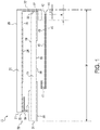
- the fastener tape assembly 10 depicted in Figure 1 includes a fastening component designated as 20, an extension component designated as 30, and a bonding component designated as 40.
- the new folding configuration includes a folded edge 22 in the fastening component 20 that: (i) receives a corresponding edge 32 of the extension component 30, and (ii) is offset from a corresponding edge 42 of the bonding component 40 of the tape assembly.
- the folded edge 42 of the bonding component 40 need not extend to, or be coextensive with, the folded edge 22 of the fastening component 20.
- this feature is illustrated as the dimensional offset B that extends beyond the folded edge 42 of the bonding component 40.
- the fact that the edge 42 of the bonding component 40 is not extending beyond one or both of the corresponding edges (32 edge, 22 folded edge) of the extension component 30 and/or the fastening component 20, is a benefit in many applications of the tape assemblies. This is because thinner materials can then be used for the bonding component 40 since stacking rolls of the tape assemblies in a pallet for example, will not affect the roll quality.
- a relatively thin material is used for the bonding component in a conventional fastener tape assembly and in a configuration in which the bonding component extends beyond the edge(s) of the fastening component and/or the extension component, that thin material will fold over resulting in a loss of bonding.
- relatively thin materials can be used for one or more or all of the fastening component, extension component, and bonding component.
- the fastening component has a thickness within a range of from about 30 ⁇ m to about 120 ⁇ m and particularly from about 50 ⁇ m to about 90 ⁇ m.
- the extension component has a thickness within a range of from about 30 ⁇ m to about 120 ⁇ m, and particularly from about 50 ⁇ m to about 90 ⁇ m.
- the bonding component has a thickness within a range of from about 15 ⁇ m to about 120 ⁇ m, and particularly from about 20 ⁇ m to about 50 ⁇ m.
- the total thickness of the fastener tape assembly is typically within a range of from about 200 ⁇ m to about 600 ⁇ m, and in many embodiments from about 250 ⁇ m to about 500 ⁇ m.
- this new folding configuration can in certain applications enable the use of thinner materials for the tape assembly and its components. This is because rolls of fastener tape incorporating the new folding configuration will no longer be carried on a portion of the bonding component otherwise extending to the fold location. Instead, such rolls will be carried on a significantly more stable portion of the tape assembly.
- Utilizing this new folding configuration also promotes dimensional certainty as to the location at which the fastener tape assembly will open.
- a face 38 of the extension component 30 of the fastener tape assembly 10 that is directed toward the bonding component 40 can include a region of patterned adhesive 35 and/or at least one adhesive-free region 33 that is free of adhesive or "adhesive-free.”
- the noted face 38 of the extension component 30 which includes a reduced face area of adhesive due to the adhesive-free region 33 and/or the region of patterned adhesive 35, will not interfere or interfere significantly less as compared to conventional tape constructions, with disposal of the diaper.
- the present subject matter includes a wide array of embodiments and that the previously described folding configuration can be used with, or without, the adhesive aspects for the extension component.
- fastener tape assemblies that include (i) the new folding configuration, (ii) region of patterned adhesive or adhesive-free region on the extension component, or both (i) and (ii).
- the attachment of the bonding component 40 to the extension component 30 of the fastener tape systems of the present subject matter can be in a variety of different forms including, but not limited to, a U-bond or utilize a U-bond strip, or in the form of a Y-bond as described in US 6,656,171 .
- Figure 1 illustrates additional features and aspects of the present subject matter fastener tape assemblies and systems of the present subject matter.
- a typical dimension for the "foldover,” shown in the figures as “A” is within a range of from 4 to 10 mm, and more particularly from 4 to 6 mm, with 5 mm being useful for many applications.
- a typical total tape assembly width shown as “W” is from about 50 to 80 mm, with total widths of about 70.3 mm, about 69 mm, and about 62 mm being useful for certain applications.
- a significant aspect of the new folding configuration is that the difference between the foldover dimension A and the extent of dimensional offset B is sufficient in order to avoid delamination of the bonding component from the diaper.
- this difference i.e., A-B, is at least about 2 mm and in certain applications is at least 3 mm.
- a bond or affixment between the fastening component 20 and the extension component 30 is provided by a folded edge 22 of the fastening component 20 into which a corresponding edge 32 of the extension component 30 is inserted or otherwise disposed.
- This aspect is in contrast to a prior art configuration in which a folded edge region is provided in a middle component corresponding to the extension component of the present subject matter tape assemblies, and a top component corresponding to the fastening component of the present subject matter is merely positioned on top or otherwise along the folded edge region of the middle component. That is, in the known prior art, the top component is not inserted within the folded edge region of the middle component.
- this leg portion 36 of the extension component 30 is the portion of the extension component 30 that extends beyond a U-bond or Y-bond edge 41 of the bonding component 40.
- the present subject matter includes tape assemblies free of this leg portion 36.
- the present subject matter includes tape assemblies that include additional components such as for example an extra film, strip or like component that is folded in a U-bond configuration to provide a bond between the extension component 30 and the bonding component 40.
- additional components such as coated tape components could be used.
- the fastening component 20 defines a first face 28 and a second face 29 oppositely directed from the first face 28.
- the fastening component 20 also defines a distal edge 21 generally opposite from the folded edge 22.
- An adhesive region 24 extends along at least a portion of the first face 28 of the fastening component 20.
- a fingerlift 50 is provided proximate the distal edge 21 of the fastening component 20.
- the fingerlift 50 typically includes a tab 54 for gripping by a user and a region 52 of adhesive for securing the tab 54 to the fastening component 20 and typically to the first face 28.
- the extension component 30 defines a face 39 oppositely directed from the face 38. And, the extension component 30 defines a distal end 31 opposite from the edge 32. In addition to the adhesive-free region 33 and the region of patterned adhesive 35, an adhesive region 37 is disposed along the face 38 of the extension component 30 for promoting and/or maintaining closure of the fastener tape assembly 10.
- the bonding component 40 defines a first face 48 and a second face 49 generally oppositely directed from the first face 48.
- the bonding component 40 also includes a region 44 of adhesive disposed along at least a portion of the first face 48 of the bonding component 40.
- the region 44 of adhesive is for bonding or securing the fastener tape assembly 10 to a diaper or other substrate.
- FIG. 1 The present subject matter also provides variations of the fastener tape assembly 10 depicted in Figure 1 .
- Figures 2 , 3, 4, and 5 illustrate additional embodiments of fastener tape assemblies 210, 310, 410, and 510, respectively.
- the fastener tape assemblies comprise the same or similar components as previously described in association with the fastener tape assembly 10 of Figure 1 , and thus use like numbering of such components.
- the fastener tape assemblies 210, 310, 410, and 510 each comprise a fastening component 220, 320, 420, and 520, respectively, which is the same or similar as the fastening component 20 of assembly 10 shown in Figure 1 .
- the fastener tape assemblies 210, 310, 410, and 510 include several variations as compared to the fastener tape assembly 10 of Figure 1 as follows.
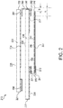
- Fastener tape assembly 210 shown in Figure 2 includes an ancillary affixment component or first "folded edge" 260.
- This component is typically separate from the fastening component 220.
- the first folded edge 260 includes two legs 261 and 262 between which is disposed an edge 232 of the extension component 230.
- the leg 261 is positioned between the exposed face of the adhesive region 224 of the fastening component 220 and a face 239 of the extension component 230.
- the leg 262 is positioned between the adhesive region 237 of the extension component 230 and a face 249 of the bonding component 240.
- the folded edge 260 can be in the form of a U-bond or Y-bond as known in the art. Use of the folded edge component 260 enables avoidance of the folded edge 222 of the fastening component 220 of the fastener tape assembly 210.
- the fastener tape assembly 210 shown in Figure 2 also comprises another or second affixment component or "folded edge" 270.
- This component is typically separate from the bonding component 240.
- the folded edge 270 includes two legs 271 and 272 between which is disposed an edge 241 of the bonding component 240.
- the folded edge 270 can be in the form of a U-bond or Y-bond as known in the art.
- the leg 271 is positioned between a face 238 of the extension component 230.
- the leg 272 is positioned to partially extend over the adhesive region 244 proximate the edge 241 of the bonding component 240.
- Use of the folded edge 270 enables avoidance of the folded edge 241 of the bonding component 240 of fastener tape assembly 210.
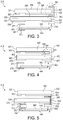
- the fastener tape assembly 310 shown in Figure 3 corresponds to the previously described fastener tape assembly 210 of Figure 2 except for the position of the first folded edge.
- the second folded edge shown as folded edge 360 is positioned to receive the edge 322 of the fastening component 320.
- a leg 361 of the folded edge 360 extends partially over a face 329 of the fastening component 320, and a leg 362 is positioned between an adhesive region 324 of the fastening component 320 and a face 339 of the extension component 330.
- the assembly 310 also comprises a second folded edge 370 which is the same or similar to the second folded edge 270 described in assembly 210 of Figure 2 .
- the folded edge 360 and the second folded edge 370 may be in the form of a U-bond or Y-bond as known in the art.
- the fastener tape assembly 410 shown in Figure 4 includes a folded edge 470 similar or the same as the folded edge 270 utilized in the fastener tape assembly 210 of Figure 2 .
- the folded edge 470 can be in the form of a U-bond or Y-bond as known in the art.
- the fastener tape assembly 410 is free of a separate folded edge corresponding to the folded edge 260 shown in Figure 2 .
- the fastener tape assembly 410 includes a configuration for the fastening component 420 similar to that of assembly 10 in Figure 1 , except that instead of positioning an edge 422 of the fastening component 420 between the extension component 430 and the bonding component 440; in fastener tape assembly 410, the edge 422 of the fastening component 420 is folded over itself and adhered or secured to a face 439 of the extension component 430 as shown in Figure 4 .
- the assembly 510 shown in Figure 5 is similar to the fastener tape assembly 210 of Figure 2 except for the positioning of a leg 572 of the second folded edge 570.
- a leg 572 of the second folded edge 570 is positioned between the extension component 530 and the bonding component 540, and specifically is directly adhered or affixed to a face 549 of the bonding component 540.
- the second folded edge 570 can be in the form of a U-bond or Y-bond as known in the art.
- a wide array of adhesives can be used in the present subject matter tape assemblies.
- adhesives are rubber-based styrene-isoprene-styrene (SIS) or styrene-butadiene-styrene (SBS)/styrene-butadiene (SB), or combinations thereof. Copolymers and/or derivatives of these and other adhesives could be utilized.
- the referenced figures illustrate typical regions of adhesive within the tape assemblies.
- one or more regions of adhesive are provided in a region of the folded edge of the fastening component and/or along a corresponding edge of the extension component to thereby bond or affix the fastening component and the extension component together upon insertion or placement of that edge of the extension component within the folded edge of the fastening component.
- Typical adhesive coatweights for all of the noted adhesive regions typically are from about 25 g/m 2 (gsm) to about 50 g/m 2 (gsm). However, the present subject matter includes coatweights less than or greater than these values.
- polymeric films and materials can be used for one or more of the fastening component, extension component, and/or bonding component.
- Nonlimiting examples of polymeric films include polypropylene and/or polyethylene.
- Nonwoven materials and nonwoven laminates can also be used in the fastening tape assemblies.
- the noted Y and U bonds can be formed from appropriately configured polypropylene films and layer(s) of nonwoven materials.
- the present subject matter also includes a wide array of articles that include the noted tape assemblies.
- the articles are disposable, i.e., the articles are formed from materials that can be recycled and/or which are relatively inexpensive.
- Nonlimiting examples of such articles include diapers, training pants, adult diapers, and in particular pant diapers.
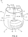
- FIG. 6 illustrates an embodiment of a disposable article in accordance with the present subject matter.
- the disposable article 100 has a front region 126, a back region 128, and a crotch region 130 between the front region 126 and the back region 128.
- a chassis 141 is provided in the front, back, and crotch regions 126, 128, and 130.
- the chassis 141 includes a liquid pervious topsheet 124, a liquid impervious backsheet 122 associated with the topsheet 124, and an absorbent core (not shown) disposed between the topsheet 124 and the backsheet 122.
- the disposable article 100 further includes a pair of front ear panels 146 each extending laterally outward from the corresponding sides of the chassis 141 in the front region 126, and a pair of extensible back ear panels 148 each extending laterally outward from the corresponding sides of the chassis 141 in the back region 128.
- Each of the ear panels 146 and 148 has an outermost edge 240 which forms an outermost edge line 242.
- the disposable article 100 further includes seams 132 each joining the front and back ear panels 146 and 148 along the corresponding edge lines 242 to form the two leg openings 134 and the waist opening 136.
- the disposable article 100 includes a fastener tape assembly 10. Although fastener tape assembly 10 is shown, it will be understood that the subject matter includes other tape assemblies, such as the fastener tape assemblies 210, 310, 410, or 510.
- the soiled disposable article 100 is torn open along the seams 132 to remove the soiled disposable article 100 from the wearer.
- the soiled disposable article 100 may be removed from the wearer by pulling down without tearing open the seams 132.
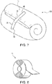
- the disposable article 100 is then folded or rolled up by keeping the crotch portion in the center so that the fastener assembly 10 is exposed along the outside of the rolled disposable article 100 for a convenient disposal as shown in Figure 7 , while containing the contents within the rolled disposable article 100.
- FIG 8 is a perspective view of a roll of fastening tape assembly 10 in accordance with the present subject matter.
- the fastening tape assembly 10 can be provided in a roll form for use by a variety of manufacturers of disposable articles. Again, although the roll is shown for fastener tape assembly 10, it will be understood that any of the assemblies 210, 310, 410, or 510 can be provided in roll form.
- the present subject matter includes all operable combinations of features and aspects described herein. Thus, for example if one feature is described in association with an embodiment and another feature is described in association with another embodiment, it will be understood that the present subject matter includes embodiments having a combination of these features.
Landscapes
- Health & Medical Sciences (AREA)
- Epidemiology (AREA)
- Engineering & Computer Science (AREA)
- Biomedical Technology (AREA)
- Heart & Thoracic Surgery (AREA)
- Vascular Medicine (AREA)
- Life Sciences & Earth Sciences (AREA)
- Animal Behavior & Ethology (AREA)
- General Health & Medical Sciences (AREA)
- Public Health (AREA)
- Veterinary Medicine (AREA)
- Absorbent Articles And Supports Therefor (AREA)
Claims (17)
- Befestigungsbandanordnung (10), welche aufweist:einen Befestigungsteil (20), der einen gefalteten Rand (22) definiert;einen Klebeteil (40), der eine erste Fläche (48) zum Fixieren an einer Windel oder einem Substrat und eine in entgegengesetzte Richtung weisende zweite Fläche (49) definiert;einen Verlängerungsteil (30) mit einem Rand (32), der innerhalb des gefalteten Randes (22) des Befestigungsteils (20) aufgenommen und zwischen dem Befestigungsteil (20) und dem Klebeteil (40) angeordnet ist;wobei der Klebeteil (40) an dem Verlängerungsteil (30) angebracht ist;wobei der Befestigungsteil (20) an dem Verlängerungsteil (30) durch den gefalteten Rand (22) des Befestigungsteils (20) fixiert ist, in den der Rand (32) des Verlängerungsteils (30) eingefügt ist; undwobei der gefaltete Rand (22) des Befestigungsteils (20) und der Rand (32) des Verlängerungsteils (30) über einen Rand (42) des Klebeteils (40) hinausragen.
- Befestigungsbandanordnung (10) nach Anspruch 1, wobei der Verlängerungsteil (30) eine Fläche (38) definiert, die dem Klebeteil (40) zugewandt ist, und die Fläche (38) (i) einen Bereich mit musterartig aufgetragenem Klebstoff (35) und/oder (ii) einen klebstofffreien Bereich (33) umfasst.
- Befestigungsbandanordnung (10) nach einem der Ansprüche 1 bis 2, wobei Klebstoff in einem Bereich des gefalteten Randes (22) vorgesehen ist, um dadurch den Befestigungsteil (20) mit dem Verlängerungsteil (30) zu verkleben; und/oderwobei Klebstoff entlang wenigstens eines Abschnitts des Randes (32) des Verlängerungsteils (30) vorgesehen ist, der innerhalb des gefalteten Randes (22) aufgenommen ist, um dadurch den Befestigungsteil (20) mit dem Verlängerungsteil (30) zu verkleben; und/oderwobei die Befestigungsbandanordnung (10) in Gestalt einer Rolle vorliegt.
- Befestigungsbandanordnung (10), umfassend:einen Befestigungsteil (20), der einen gefalteten Rand (22) definiert;einen Klebeteil (40), der eine erste Fläche (48) zum Fixieren an einer Windel oder einem Substrat und eine in entgegengesetzte Richtung weisende zweite Fläche (49) definiert;einen Verlängerungsteil (30) mit einem Rand (32), der innerhalb des gefalteten Randes (22) des Befestigungsteils (20) aufgenommen und zwischen dem Befestigungsteil (20) und dem Klebeteil (40) angeordnet ist;wobei der Klebeteil (40) an dem Verlängerungsteil (30) angebracht ist;wobei der Befestigungsteil (20) an dem Verlängerungsteil (30) durch den gefalteten Rand (22) des Befestigungsteils (20) fixiert ist, in den der Rand (32) des Verlängerungsteils (30) eingefügt ist; undwobei der Verlängerungsteil (30) eine Fläche (38) definiert, die dem Klebeteil (40) zugewandt ist, und die Fläche (38) (i) einen Bereich mit musterartig aufgetragenem Klebstoff (35) und/oder (ii) einen klebstofffreien Bereich (33) umfasst.
- Befestigungsbandanordnung (10) nach Anspruch 4, wobei der gefaltete Rand (22) des Befestigungsteils (20) und der Rand (32) des Verlängerungsteils (30) über einen Rand (42) des Klebeteils (40) hinausragen.
- Befestigungsbandanordnung (10) nach einem der Ansprüche 4 bis 5, wobei die Fläche (38) des Verlängerungsteils (30) den klebstofffreien Bereich (33) umfasst; und/oderwobei die Fläche (38) des Verlängerungsteils (30) den Bereich mit musterartig aufgetragenem Klebstoff (35) umfasst; und/oderwobei die Befestigungsbandanordnung (10) in Gestalt einer Rolle vorliegt.
- Befestigungsbandanordnung (210), welche aufweist:einen Befestigungsteil (220), der einen ersten Rand (222) und einen zweiten Rand definiert;einen Klebeteil (240), der eine erste Fläche zum Fixieren an einer Windel oder einem Substrat und eine in entgegengesetzte Richtung weisende zweite Fläche (249) definiert;einen ersten gefalteten Randteil (260) mit einem ersten Schenkel (261) und einem zweiten Schenkel (262);einen Verlängerungsteil (230) mit einem Rand (232), der zwischen dem ersten Schenkel (261) und dem zweiten Schenkel (262) des ersten gefalteten Randteils (260) aufgenommen ist, wobei der Verlängerungsteil (230) zwischen dem Befestigungsteil (220) und dem Klebeteil (240) angeordnet ist;wobei der Klebeteil (240) an dem Verlängerungsteil (230) angebracht ist;wobei der Befestigungsteil (220) an dem Verlängerungsteil (230) durch den ersten gefalteten Randteil (260) fixiert ist, in den der Rand (232) des Verlängerungsteils (230) eingefügt ist; undwobei der erste gefaltete Randteil (260) und der Rand (232) des Verlängerungsteils (230) über einen Rand (242) des Klebeteils (240) hinausragen.
- Befestigungsbandanordnung (210) nach Anspruch 7, weiterhin umfassend:einen zweiten gefalteten Randteil (270) mit einem ersten Schenkel (271) und einem zweiten Schenkel (272);wobei ein Rand (241) des Klebeteils (240) zwischen dem ersten Schenkel (271) und dem zweiten Schenkel (272) des zweiten gefalteten Randes (270) aufgenommen ist.
- Befestigungsbandanordnung (210) nach einem der Ansprüche 7 bis 8, wobei der Verlängerungsteil (230) eine Fläche (238) definiert, die dem Klebeteil (240) zugewandt ist, und die Fläche (238) (i) einen Bereich mit musterartig aufgetragenem Klebstoff (235) und/oder (ii) einen klebstofffreien Bereich umfasst; und/oderwobei Klebstoff in einem Bereich des ersten gefalteten Randes (260) vorgesehen ist, um dadurch den Befestigungsteil (220) mit dem Verlängerungsteil (230) zu verkleben; und/oderwobei Klebstoff entlang wenigstens eines Abschnitts des Randes (232) des Verlängerungsteils (230) vorgesehen ist, der innerhalb des ersten gefalteten Randes (260) aufgenommen ist, um dadurch den Befestigungsteil (220) mit dem Verlängerungsteil (230) zu verkleben; und/oderwobei die Befestigungsbandanordnung (210) in Gestalt einer Rolle vorliegt.
- Gegenstand (100), der eine Befestigungsbandanordnung (10) umfasst, wobei die Befestigungsbandanordnung (10) umfasst:einen Befestigungsteil (20), der einen gefalteten Rand (22) definiert;einen Klebeteil (40), der eine erste Fläche (48), die an dem Gegenstand (100) fixiert ist, und eine in entgegengesetzte Richtung weisende zweite Fläche (49) definiert;einen Verlängerungsteil (30) mit einem Rand (32), der innerhalb des gefalteten Randes (22) des Befestigungsteils (20) aufgenommen und zwischen dem Befestigungsteil (20) und dem Klebeteil (40) angeordnet ist;wobei der Klebeteil (40) an dem Verlängerungsteil (30) angebracht ist;wobei der Befestigungsteil (20) an dem Verlängerungsteil (30) durch den gefalteten Rand (22) des Befestigungsteils (20) fixiert ist, in den der Rand (32) des Verlängerungsteils (30) eingefügt ist; undwobei der gefaltete Rand (22) des Befestigungsteils (20) und der Rand (32) des Verlängerungsteils (30) über einen Rand (42) des Klebeteils (40) hinausragen.
- Gegenstand (100), der eine Befestigungsbandanordnung (10) umfasst, wobei die Befestigungsbandanordnung (10) umfasst:einen Befestigungsteil (20), der einen gefalteten Rand (22) definiert;einen Klebeteil (40), der eine erste Fläche (48), die an dem Gegenstand (100) fixiert ist, und eine in entgegengesetzte Richtung weisende zweite Fläche (49) definiert;einen Verlängerungsteil (30) mit einem Rand (32), der innerhalb des gefalteten Randes (22) des Befestigungsteils (20) aufgenommen und zwischen dem Befestigungsteil (20) und dem Klebeteil (40) angeordnet ist;wobei der Klebeteil (40) an dem Verlängerungsteil (30) angebracht ist;wobei der Befestigungsteil (20) an dem Verlängerungsteil (30) durch den gefalteten Rand (22) des Befestigungsteils (20) fixiert ist, in den der Rand (32) des Verlängerungsteils (30) eingefügt ist; undwobei der Verlängerungsteil (30) eine Fläche (38) definiert, die dem Klebeteil (40) zugewandt ist, und die Fläche (38) (i) einen Bereich mit musterartig aufgetragenem Klebstoff (35) und/oder (ii) einen klebstofffreien Bereich (33) umfasst.
- Gegenstand (100), der eine Befestigungsbandanordnung (210) umfasst, wobei die Befestigungsbandanordnung (210) umfasst:einen Befestigungsteil (220), der einen ersten Rand (222) und einen zweiten Rand definiert;einen Klebeteil (240), der eine erste Fläche zum Fixieren an dem Gegenstand (100) und eine in entgegengesetzte Richtung weisende zweite Fläche (249) definiert;einen ersten gefalteten Randteil (260) mit einem ersten Schenkel (261) und einem zweiten Schenkel (262);einen Verlängerungsteil (230) mit einem Rand (232), der zwischen dem ersten Schenkel (261) und dem zweiten Schenkel (262) des ersten gefalteten Randteils (260) aufgenommen ist, wobei der Verlängerungsteil (230) zwischen dem Befestigungsteil (220) und dem Klebeteil (240) angeordnet ist;wobei der Klebeteil (240) an dem Verlängerungsteil (230) angebracht ist;wobei der Befestigungsteil (220) an dem Verlängerungsteil (230) durch den ersten gefalteten Randteil (260) fixiert ist, in den der Rand (232) des Verlängerungsteils (230) eingefügt ist; undwobei der erste gefaltete Randteil (260) und der Rand (232) des Verlängerungsteils (230) über einen Rand (242) des Klebeteils (240) hinausragen.
- Gegenstand (100) nach Anspruch 12, wobei die Befestigungsbandanordnung (210) weiterhin umfasst:einen zweiten gefalteten Randteil (270) mit einem ersten Schenkel (271) und einem zweiten Schenkel (272);wobei ein Rand (241) des Klebeteils (240) zwischen dem ersten Schenkel (271) und dem zweiten Schenkel (272) des zweiten gefalteten Randteils (270) aufgenommen ist.
- Gegenstand (100) nach einem der Ansprüche 10 bis 13, wobei der Gegenstand (100) eine Windel ist.
- Gegenstand (100) nach Anspruch 14, wobei der Gegenstand (100) eine Höschenwindel ist.
- Befestigungsbandanordnung (10; 210) nach einem der Ansprüche 1 bis 9, wobei der Befestigungsteil (20; 220), der Verlängerungsteil (30; 230) und/oder der Klebeteil (40; 240) eine Polymerfolie umfasst, die aus der Gruppe ausgewählt ist, die aus einem Polypropylen, einem Polyethylen und einer Kombination davon besteht.
- Befestigungsbandanordnung (10; 210) nach einem der Ansprüche 1 bis 9, wobei sich ein Klebebereich (24; 224) entlang wenigstens eines Abschnitts einer ersten Fläche (28) des Befestigungsteils (20; 220) erstreckt.
Priority Applications (1)
| Application Number | Priority Date | Filing Date | Title |
|---|---|---|---|
| PL17719132T PL3442485T3 (pl) | 2016-04-13 | 2017-04-12 | Zespoły taśmy klejącej |
Applications Claiming Priority (2)
| Application Number | Priority Date | Filing Date | Title |
|---|---|---|---|
| US201662321821P | 2016-04-13 | 2016-04-13 | |
| PCT/US2017/027136 WO2017180702A1 (en) | 2016-04-13 | 2017-04-12 | Adhesive tape assemblies |
Publications (2)
| Publication Number | Publication Date |
|---|---|
| EP3442485A1 EP3442485A1 (de) | 2019-02-20 |
| EP3442485B1 true EP3442485B1 (de) | 2021-10-27 |
Family
ID=58610049
Family Applications (1)
| Application Number | Title | Priority Date | Filing Date |
|---|---|---|---|
| EP17719132.7A Active EP3442485B1 (de) | 2016-04-13 | 2017-04-12 | Klebebandanordnungen |
Country Status (6)
| Country | Link |
|---|---|
| US (1) | US11298277B2 (de) |
| EP (1) | EP3442485B1 (de) |
| JP (1) | JP7091251B2 (de) |
| ES (1) | ES2896736T3 (de) |
| PL (1) | PL3442485T3 (de) |
| WO (1) | WO2017180702A1 (de) |
Families Citing this family (6)
| Publication number | Priority date | Publication date | Assignee | Title |
|---|---|---|---|---|
| JP7212458B2 (ja) * | 2017-08-08 | 2023-01-25 | 花王株式会社 | パンツ型使い捨ておむつ |
| EP3761935A1 (de) * | 2018-03-05 | 2021-01-13 | Avery Dennison Corporation | Klebebandanordnungen |
| JP7106211B2 (ja) * | 2018-04-24 | 2022-07-26 | 花王株式会社 | パンツ型使い捨ておむつ |
| DE102019108393A1 (de) | 2019-01-31 | 2020-08-06 | Lohmann-Koester Gmbh & Co. Kg | Windelverschlussband sowie Halbzeugstreifen und Windel |
| US20220087881A1 (en) * | 2020-09-22 | 2022-03-24 | The Procter & Gamble Company | Absorbent articles with patterned front ears |
| KR102314264B1 (ko) * | 2021-06-15 | 2021-10-19 | 주식회사 라크인더스트리 | 일회용 기저귀 후크부재를 제공하기 위한 롤형 훅테이프 |
Family Cites Families (18)
| Publication number | Priority date | Publication date | Assignee | Title |
|---|---|---|---|---|
| US2162108A (en) | 1939-06-13 | Method for forming concrete | ||
| FR2413891A1 (fr) * | 1978-01-06 | 1979-08-03 | Beghin Say Sa | Attaches pliees et procede de fabrication |
| US4778701A (en) * | 1986-05-27 | 1988-10-18 | Minnesota Mining And Manufacturing Company | Composite prelaminated tape system |
| US4801480A (en) * | 1987-11-03 | 1989-01-31 | Minnesota Mining And Manufacturing Company | Composite prelaminated tape system |
| DE4033850A1 (de) | 1990-10-24 | 1992-04-30 | Minnesota Mining & Mfg | Zu einer rolle endlos aufgewickeltes, zusammengesetztes laminatklebeband und verfahren zur herstellung der rolle des laminatklebebandes |
| JP3544735B2 (ja) | 1995-03-07 | 2004-07-21 | 日東電工株式会社 | Z型粘着テープ |
| US5549592A (en) * | 1995-04-03 | 1996-08-27 | Kimberly-Clark Corporation | Absorbent article with a laminated tape |
| JP3217289B2 (ja) | 1997-01-31 | 2001-10-09 | ユニ・チャーム株式会社 | 使い捨ての体液吸収性着用物品 |
| ATE369915T1 (de) | 1998-05-01 | 2007-09-15 | Gen Probe Inc | Inkubator für automatische analysevorrichtung |
| US6656171B1 (en) | 1999-08-26 | 2003-12-02 | The Procter & Gamble Company | Fastener device and disposable product using the same |
| US7291371B2 (en) | 2003-02-12 | 2007-11-06 | Avery Dennison Corporation | Mechanical closure tape |
| JP2006045417A (ja) | 2004-08-06 | 2006-02-16 | Nitto Lifetech Kk | 粘着テープ又はシート、および紙おむつ |
| US8080198B2 (en) | 2006-10-20 | 2011-12-20 | Avery Dennison Corporation | Elastic diaper component |
| JP5275344B2 (ja) | 2007-06-15 | 2013-08-28 | エイブリィ・デニソン・コーポレイション | 留め具 |
| WO2009143326A1 (en) * | 2008-05-23 | 2009-11-26 | The Procter & Gamble Company | Methods for the manufacture of fastener tabs |
| BR112013007424B1 (pt) | 2010-09-28 | 2020-08-04 | Avery Dennison Corporation | Aba de retenção e fralda tendo uma região da cintura anterior |
| EP3378455B1 (de) | 2011-03-22 | 2022-10-19 | Avery Dennison Corporation | Verschlussband mit strukturiertem klebstoff |
| WO2012154659A1 (en) | 2011-05-06 | 2012-11-15 | Avery Dennison Corporation | Fastening tag for disposable absorbent article |
-
2017
- 2017-04-12 US US16/090,958 patent/US11298277B2/en active Active
- 2017-04-12 PL PL17719132T patent/PL3442485T3/pl unknown
- 2017-04-12 EP EP17719132.7A patent/EP3442485B1/de active Active
- 2017-04-12 WO PCT/US2017/027136 patent/WO2017180702A1/en active Application Filing
- 2017-04-12 ES ES17719132T patent/ES2896736T3/es active Active
- 2017-04-12 JP JP2018553386A patent/JP7091251B2/ja active Active
Non-Patent Citations (1)
| Title |
|---|
| None * |
Also Published As
| Publication number | Publication date |
|---|---|
| US20190117480A1 (en) | 2019-04-25 |
| US11298277B2 (en) | 2022-04-12 |
| JP7091251B2 (ja) | 2022-06-27 |
| PL3442485T3 (pl) | 2022-02-21 |
| EP3442485A1 (de) | 2019-02-20 |
| JP2019511320A (ja) | 2019-04-25 |
| ES2896736T3 (es) | 2022-02-25 |
| WO2017180702A1 (en) | 2017-10-19 |
Similar Documents
| Publication | Publication Date | Title |
|---|---|---|
| EP3442485B1 (de) | Klebebandanordnungen | |
| US5603794A (en) | Method for manufacturing angled tape tabs for use with disposable absorbent articles | |
| EP1711152B1 (de) | Hosenartiges einwegkleidungsstück mit verbesserten befestigungssystemen | |
| US8496640B2 (en) | Release tape-free fasteners and disposable absorbent articles utilizing the same | |
| US9724251B2 (en) | Refastenable absorbent article | |
| SE508614C2 (sv) | Byxblöja eller byxbinda | |
| JP7206033B2 (ja) | 吸収性物品用固定部材 | |
| JPH1128223A (ja) | 使い捨ての体液吸収性着用物品 | |
| US8601665B2 (en) | Refastenable absorbent article | |
| EP1214034B1 (de) | Verschluss und wegwerfartikel mit derartigem verschluss | |
| MX2013013038A (es) | Pestaña de fijacion para articulo absorbente desechable. | |
| JP2003079658A (ja) | 使い捨ておむつ | |
| CA2192178C (en) | Method for manufacturing one-piece tape tabs for use with disposable absorbent articles | |
| JP4235479B2 (ja) | 後処理テープを備えた使い捨ておむつ | |
| JPH1085254A (ja) | 使い捨ての体液吸収性着用物品 | |
| US5681306A (en) | Disposable absorbent articles having improved tape tab fasteners | |
| EP0877589B1 (de) | Absorbierendes wegwerferzeugnis mit bandstreifenverschlüssen | |
| JP2003245307A (ja) | テープファスナを備えた使い捨て着用物品 | |
| CA2473291C (en) | Disposable wearing article | |
| CN215652075U (zh) | 紧固带组件和包括紧固带组件的尿布 | |
| US20210000664A1 (en) | Adhesive Tape Assemblies | |
| JP2023547603A (ja) | 粘着テープアセンブリ | |
| JP2004344678A (ja) | ウイング付吸収性物品 |
Legal Events
| Date | Code | Title | Description |
|---|---|---|---|
| STAA | Information on the status of an ep patent application or granted ep patent |
Free format text: STATUS: UNKNOWN |
|
| STAA | Information on the status of an ep patent application or granted ep patent |
Free format text: STATUS: THE INTERNATIONAL PUBLICATION HAS BEEN MADE |
|
| PUAI | Public reference made under article 153(3) epc to a published international application that has entered the european phase |
Free format text: ORIGINAL CODE: 0009012 |
|
| STAA | Information on the status of an ep patent application or granted ep patent |
Free format text: STATUS: REQUEST FOR EXAMINATION WAS MADE |
|
| 17P | Request for examination filed |
Effective date: 20181011 |
|
| AK | Designated contracting states |
Kind code of ref document: A1 Designated state(s): AL AT BE BG CH CY CZ DE DK EE ES FI FR GB GR HR HU IE IS IT LI LT LU LV MC MK MT NL NO PL PT RO RS SE SI SK SM TR |
|
| AX | Request for extension of the european patent |
Extension state: BA ME |
|
| DAV | Request for validation of the european patent (deleted) | ||
| DAX | Request for extension of the european patent (deleted) | ||
| GRAJ | Information related to disapproval of communication of intention to grant by the applicant or resumption of examination proceedings by the epo deleted |
Free format text: ORIGINAL CODE: EPIDOSDIGR1 |
|
| STAA | Information on the status of an ep patent application or granted ep patent |
Free format text: STATUS: GRANT OF PATENT IS INTENDED |
|
| GRAJ | Information related to disapproval of communication of intention to grant by the applicant or resumption of examination proceedings by the epo deleted |
Free format text: ORIGINAL CODE: EPIDOSDIGR1 |
|
| GRAP | Despatch of communication of intention to grant a patent |
Free format text: ORIGINAL CODE: EPIDOSNIGR1 |
|
| STAA | Information on the status of an ep patent application or granted ep patent |
Free format text: STATUS: REQUEST FOR EXAMINATION WAS MADE |
|
| INTG | Intention to grant announced |
Effective date: 20201028 |
|
| INTC | Intention to grant announced (deleted) | ||
| GRAP | Despatch of communication of intention to grant a patent |
Free format text: ORIGINAL CODE: EPIDOSNIGR1 |
|
| STAA | Information on the status of an ep patent application or granted ep patent |
Free format text: STATUS: GRANT OF PATENT IS INTENDED |
|
| INTG | Intention to grant announced |
Effective date: 20201207 |
|
| GRAJ | Information related to disapproval of communication of intention to grant by the applicant or resumption of examination proceedings by the epo deleted |
Free format text: ORIGINAL CODE: EPIDOSDIGR1 |
|
| STAA | Information on the status of an ep patent application or granted ep patent |
Free format text: STATUS: REQUEST FOR EXAMINATION WAS MADE |
|
| INTC | Intention to grant announced (deleted) | ||
| GRAP | Despatch of communication of intention to grant a patent |
Free format text: ORIGINAL CODE: EPIDOSNIGR1 |
|
| STAA | Information on the status of an ep patent application or granted ep patent |
Free format text: STATUS: GRANT OF PATENT IS INTENDED |
|
| INTG | Intention to grant announced |
Effective date: 20210507 |
|
| GRAS | Grant fee paid |
Free format text: ORIGINAL CODE: EPIDOSNIGR3 |
|
| GRAA | (expected) grant |
Free format text: ORIGINAL CODE: 0009210 |
|
| STAA | Information on the status of an ep patent application or granted ep patent |
Free format text: STATUS: THE PATENT HAS BEEN GRANTED |
|
| AK | Designated contracting states |
Kind code of ref document: B1 Designated state(s): AL AT BE BG CH CY CZ DE DK EE ES FI FR GB GR HR HU IE IS IT LI LT LU LV MC MK MT NL NO PL PT RO RS SE SI SK SM TR |
|
| REG | Reference to a national code |
Ref country code: GB Ref legal event code: FG4D |
|
| REG | Reference to a national code |
Ref country code: CH Ref legal event code: EP |
|
| REG | Reference to a national code |
Ref country code: AT Ref legal event code: REF Ref document number: 1441171 Country of ref document: AT Kind code of ref document: T Effective date: 20211115 |
|
| REG | Reference to a national code |
Ref country code: DE Ref legal event code: R096 Ref document number: 602017048233 Country of ref document: DE |
|
| REG | Reference to a national code |
Ref country code: IE Ref legal event code: FG4D |
|
| REG | Reference to a national code |
Ref country code: NL Ref legal event code: FP |
|
| REG | Reference to a national code |
Ref country code: LT Ref legal event code: MG9D Ref country code: ES Ref legal event code: FG2A Ref document number: 2896736 Country of ref document: ES Kind code of ref document: T3 Effective date: 20220225 |
|
| REG | Reference to a national code |
Ref country code: AT Ref legal event code: MK05 Ref document number: 1441171 Country of ref document: AT Kind code of ref document: T Effective date: 20211027 |
|
| PG25 | Lapsed in a contracting state [announced via postgrant information from national office to epo] |
Ref country code: RS Free format text: LAPSE BECAUSE OF FAILURE TO SUBMIT A TRANSLATION OF THE DESCRIPTION OR TO PAY THE FEE WITHIN THE PRESCRIBED TIME-LIMIT Effective date: 20211027 Ref country code: LT Free format text: LAPSE BECAUSE OF FAILURE TO SUBMIT A TRANSLATION OF THE DESCRIPTION OR TO PAY THE FEE WITHIN THE PRESCRIBED TIME-LIMIT Effective date: 20211027 Ref country code: FI Free format text: LAPSE BECAUSE OF FAILURE TO SUBMIT A TRANSLATION OF THE DESCRIPTION OR TO PAY THE FEE WITHIN THE PRESCRIBED TIME-LIMIT Effective date: 20211027 Ref country code: BG Free format text: LAPSE BECAUSE OF FAILURE TO SUBMIT A TRANSLATION OF THE DESCRIPTION OR TO PAY THE FEE WITHIN THE PRESCRIBED TIME-LIMIT Effective date: 20220127 Ref country code: AT Free format text: LAPSE BECAUSE OF FAILURE TO SUBMIT A TRANSLATION OF THE DESCRIPTION OR TO PAY THE FEE WITHIN THE PRESCRIBED TIME-LIMIT Effective date: 20211027 |
|
| PG25 | Lapsed in a contracting state [announced via postgrant information from national office to epo] |
Ref country code: IS Free format text: LAPSE BECAUSE OF FAILURE TO SUBMIT A TRANSLATION OF THE DESCRIPTION OR TO PAY THE FEE WITHIN THE PRESCRIBED TIME-LIMIT Effective date: 20220227 Ref country code: SE Free format text: LAPSE BECAUSE OF FAILURE TO SUBMIT A TRANSLATION OF THE DESCRIPTION OR TO PAY THE FEE WITHIN THE PRESCRIBED TIME-LIMIT Effective date: 20211027 Ref country code: PT Free format text: LAPSE BECAUSE OF FAILURE TO SUBMIT A TRANSLATION OF THE DESCRIPTION OR TO PAY THE FEE WITHIN THE PRESCRIBED TIME-LIMIT Effective date: 20220228 Ref country code: NO Free format text: LAPSE BECAUSE OF FAILURE TO SUBMIT A TRANSLATION OF THE DESCRIPTION OR TO PAY THE FEE WITHIN THE PRESCRIBED TIME-LIMIT Effective date: 20220127 Ref country code: LV Free format text: LAPSE BECAUSE OF FAILURE TO SUBMIT A TRANSLATION OF THE DESCRIPTION OR TO PAY THE FEE WITHIN THE PRESCRIBED TIME-LIMIT Effective date: 20211027 Ref country code: HR Free format text: LAPSE BECAUSE OF FAILURE TO SUBMIT A TRANSLATION OF THE DESCRIPTION OR TO PAY THE FEE WITHIN THE PRESCRIBED TIME-LIMIT Effective date: 20211027 Ref country code: GR Free format text: LAPSE BECAUSE OF FAILURE TO SUBMIT A TRANSLATION OF THE DESCRIPTION OR TO PAY THE FEE WITHIN THE PRESCRIBED TIME-LIMIT Effective date: 20220128 |
|
| PGFP | Annual fee paid to national office [announced via postgrant information from national office to epo] |
Ref country code: PL Payment date: 20220325 Year of fee payment: 6 |
|
| REG | Reference to a national code |
Ref country code: DE Ref legal event code: R081 Ref document number: 602017048233 Country of ref document: DE Owner name: AVERY DENNISON CORPORATION, MENTOR, US Free format text: FORMER OWNER: AVERY DENNISON CORP., GLENDALE, CA, US |
|
| REG | Reference to a national code |
Ref country code: DE Ref legal event code: R097 Ref document number: 602017048233 Country of ref document: DE |
|
| PG25 | Lapsed in a contracting state [announced via postgrant information from national office to epo] |
Ref country code: SM Free format text: LAPSE BECAUSE OF FAILURE TO SUBMIT A TRANSLATION OF THE DESCRIPTION OR TO PAY THE FEE WITHIN THE PRESCRIBED TIME-LIMIT Effective date: 20211027 Ref country code: SK Free format text: LAPSE BECAUSE OF FAILURE TO SUBMIT A TRANSLATION OF THE DESCRIPTION OR TO PAY THE FEE WITHIN THE PRESCRIBED TIME-LIMIT Effective date: 20211027 Ref country code: RO Free format text: LAPSE BECAUSE OF FAILURE TO SUBMIT A TRANSLATION OF THE DESCRIPTION OR TO PAY THE FEE WITHIN THE PRESCRIBED TIME-LIMIT Effective date: 20211027 Ref country code: EE Free format text: LAPSE BECAUSE OF FAILURE TO SUBMIT A TRANSLATION OF THE DESCRIPTION OR TO PAY THE FEE WITHIN THE PRESCRIBED TIME-LIMIT Effective date: 20211027 Ref country code: DK Free format text: LAPSE BECAUSE OF FAILURE TO SUBMIT A TRANSLATION OF THE DESCRIPTION OR TO PAY THE FEE WITHIN THE PRESCRIBED TIME-LIMIT Effective date: 20211027 Ref country code: CZ Free format text: LAPSE BECAUSE OF FAILURE TO SUBMIT A TRANSLATION OF THE DESCRIPTION OR TO PAY THE FEE WITHIN THE PRESCRIBED TIME-LIMIT Effective date: 20211027 |
|
| REG | Reference to a national code |
Ref country code: BE Ref legal event code: PD Owner name: AVERY DENNISON CORPORATION; US Free format text: DETAILS ASSIGNMENT: CHANGE OF OWNER(S), OTHER; FORMER OWNER NAME: AVERY DENNISON CORPORATION Effective date: 20220602 |
|
| RAP4 | Party data changed (patent owner data changed or rights of a patent transferred) |
Owner name: AVERY DENNISON CORPORATION |
|
| PLBE | No opposition filed within time limit |
Free format text: ORIGINAL CODE: 0009261 |
|
| STAA | Information on the status of an ep patent application or granted ep patent |
Free format text: STATUS: NO OPPOSITION FILED WITHIN TIME LIMIT |
|
| 26N | No opposition filed |
Effective date: 20220728 |
|
| PG25 | Lapsed in a contracting state [announced via postgrant information from national office to epo] |
Ref country code: AL Free format text: LAPSE BECAUSE OF FAILURE TO SUBMIT A TRANSLATION OF THE DESCRIPTION OR TO PAY THE FEE WITHIN THE PRESCRIBED TIME-LIMIT Effective date: 20211027 |
|
| PG25 | Lapsed in a contracting state [announced via postgrant information from national office to epo] |
Ref country code: SI Free format text: LAPSE BECAUSE OF FAILURE TO SUBMIT A TRANSLATION OF THE DESCRIPTION OR TO PAY THE FEE WITHIN THE PRESCRIBED TIME-LIMIT Effective date: 20211027 |
|
| REG | Reference to a national code |
Ref country code: CH Ref legal event code: PL |
|
| PG25 | Lapsed in a contracting state [announced via postgrant information from national office to epo] |
Ref country code: MC Free format text: LAPSE BECAUSE OF FAILURE TO SUBMIT A TRANSLATION OF THE DESCRIPTION OR TO PAY THE FEE WITHIN THE PRESCRIBED TIME-LIMIT Effective date: 20211027 Ref country code: LU Free format text: LAPSE BECAUSE OF NON-PAYMENT OF DUE FEES Effective date: 20220412 Ref country code: LI Free format text: LAPSE BECAUSE OF NON-PAYMENT OF DUE FEES Effective date: 20220430 Ref country code: CH Free format text: LAPSE BECAUSE OF NON-PAYMENT OF DUE FEES Effective date: 20220430 |
|
| PG25 | Lapsed in a contracting state [announced via postgrant information from national office to epo] |
Ref country code: IE Free format text: LAPSE BECAUSE OF NON-PAYMENT OF DUE FEES Effective date: 20220412 |
|
| PGFP | Annual fee paid to national office [announced via postgrant information from national office to epo] |
Ref country code: FR Payment date: 20230320 Year of fee payment: 7 |
|
| PGFP | Annual fee paid to national office [announced via postgrant information from national office to epo] |
Ref country code: BE Payment date: 20230322 Year of fee payment: 7 |
|
| P01 | Opt-out of the competence of the unified patent court (upc) registered |
Effective date: 20230526 |
|
| PGFP | Annual fee paid to national office [announced via postgrant information from national office to epo] |
Ref country code: IT Payment date: 20230424 Year of fee payment: 7 Ref country code: ES Payment date: 20230509 Year of fee payment: 7 Ref country code: DE Payment date: 20230320 Year of fee payment: 7 |
|
| PGFP | Annual fee paid to national office [announced via postgrant information from national office to epo] |
Ref country code: TR Payment date: 20230411 Year of fee payment: 7 |
|
| PG25 | Lapsed in a contracting state [announced via postgrant information from national office to epo] |
Ref country code: HU Free format text: LAPSE BECAUSE OF FAILURE TO SUBMIT A TRANSLATION OF THE DESCRIPTION OR TO PAY THE FEE WITHIN THE PRESCRIBED TIME-LIMIT; INVALID AB INITIO Effective date: 20170412 |
|
| PGFP | Annual fee paid to national office [announced via postgrant information from national office to epo] |
Ref country code: NL Payment date: 20240319 Year of fee payment: 8 |
|
| PG25 | Lapsed in a contracting state [announced via postgrant information from national office to epo] |
Ref country code: MK Free format text: LAPSE BECAUSE OF FAILURE TO SUBMIT A TRANSLATION OF THE DESCRIPTION OR TO PAY THE FEE WITHIN THE PRESCRIBED TIME-LIMIT Effective date: 20211027 Ref country code: CY Free format text: LAPSE BECAUSE OF FAILURE TO SUBMIT A TRANSLATION OF THE DESCRIPTION OR TO PAY THE FEE WITHIN THE PRESCRIBED TIME-LIMIT Effective date: 20211027 |
|
| PGFP | Annual fee paid to national office [announced via postgrant information from national office to epo] |
Ref country code: GB Payment date: 20240314 Year of fee payment: 8 |