EP3441778A1 - Magnetfeldsensor - Google Patents
Magnetfeldsensor Download PDFInfo
- Publication number
- EP3441778A1 EP3441778A1 EP18179518.8A EP18179518A EP3441778A1 EP 3441778 A1 EP3441778 A1 EP 3441778A1 EP 18179518 A EP18179518 A EP 18179518A EP 3441778 A1 EP3441778 A1 EP 3441778A1
- Authority
- EP
- European Patent Office
- Prior art keywords
- housing part
- element housing
- magnetic field
- sensor element
- field sensor
- Prior art date
- Legal status (The legal status is an assumption and is not a legal conclusion. Google has not performed a legal analysis and makes no representation as to the accuracy of the status listed.)
- Granted
Links
Images


Classifications
-
- G—PHYSICS
- G01—MEASURING; TESTING
- G01D—MEASURING NOT SPECIALLY ADAPTED FOR A SPECIFIC VARIABLE; ARRANGEMENTS FOR MEASURING TWO OR MORE VARIABLES NOT COVERED IN A SINGLE OTHER SUBCLASS; TARIFF METERING APPARATUS; MEASURING OR TESTING NOT OTHERWISE PROVIDED FOR
- G01D11/00—Component parts of measuring arrangements not specially adapted for a specific variable
- G01D11/24—Housings ; Casings for instruments
- G01D11/245—Housings for sensors
-
- G—PHYSICS
- G01—MEASURING; TESTING
- G01R—MEASURING ELECTRIC VARIABLES; MEASURING MAGNETIC VARIABLES
- G01R33/00—Arrangements or instruments for measuring magnetic variables
- G01R33/0047—Housings or packaging of magnetic sensors ; Holders
Definitions
- the invention relates to a magnetic field sensor with a device housing having at least one sensor element housing part and a connection element housing part, wherein the connection element housing part is arranged at least partially in the sensor element housing part in the direction of a longitudinal axis of the device housing and wherein the connection element housing part and the sensor element housing part are connected by means of a flange.
- Such a magnetic field sensor is known for example as a so-called speed sensor or rotary encoder for a tachograph in a motor vehicle, in particular a commercial vehicle.
- the magnetic field sensor has a sensor head and is screwed into a transmission housing of a transmission of the motor vehicle. By means of the sensor head, the magnetic field sensor detects a movement of a transmission gear wheel of the transmission. The movement of the transmission gear is a measure of the speed of the motor vehicle.
- a part of the sensor element housing part is part of the sensor head.
- the magnetic field sensor is connected to the tachograph of the motor vehicle via a plug socket comprising the terminal element housing part and terminal contacts. Due to the required high reliability of recorded with the tachograph data, it is inter alia important to avoid manipulation of the magnetic field sensor and from such manipulation following data falsifications.
- the object of the invention is to provide a magnetic field sensor of the type mentioned, which has a high security against manipulation.
- the simultaneous provision of a toothing of the two housing parts sensor element housing part and connecting element housing part and arranged in the toothing having a toothing region, the connection of the two housing parts securing seal can thus be made particularly reliable recognizable because the separation not only to an opening, in particular to a bending, the Flaring leads, but also requires a detachment of the seal and / or its destruction. Manipulations are thus particularly reliable recognizable.
- the toothing of the connection element housing part with the sensor element housing part additionally forms an anti-rotation lock of the two housing parts to one another, whereby a high torsional strength is achieved.
- the seal is preferably arranged by means of an adhesive bond on the device housing outside, that is, the seal is preferably glued to the device housing in the toothing region.
- the seal may for example be a seal, which is destroyed in a separation of the sensor element housing part and connector housing part.
- the seal may be, for example, a so-called VOID seal, which in a Removing, for example, peeling or tearing, the seal from the device housing leaves a lettering on the outside of the device housing as well as in or on the seal itself.
- the flanging is produced in a production of the magnetic field sensor preferably in that a thin-walled annular region on the sensor element housing part is bent over a collar on the connection element housing part, namely flanged.
- the material for the sensor element housing part is designed in such a way that it does not permit repeated bending up and down, as would occur, for example, when the flange is opened and closed. Further preferably, the material is designed such that it comes to visible fractures in the material even with a single opening of the flange.
- the material is designed such that (for example, by stretching the material when opening the flange) a renewed bending, that is a re-closing of the flange, after opening the flange is not possible with the result of a visually flawless flanging.
- the material for the sensor element housing part is preferably a very brittle, high-strength material.
- the longitudinal axis of the device housing is that axis of the device housing that corresponds to the direction of its greatest extent.
- the longitudinal axis of the device housing is preferably also the longitudinal axis of the magnetic field sensor.
- the device housing of the magnetic field sensor may in particular be cylindrical. Then there is a cylindrical magnetic field sensor.
- the magnetic field sensor is rod-shaped.
- the toothed section of the sensor element housing part has a recess in the sensor element housing part and the toothed section of the terminal housing part has a projection on the terminal housing part, and the toothed portion of the terminal housing part engages the toothed section of the sensor element housing part in a form-fitting manner.
- the curling on the device housing outside runs around the device housing and has a crimp interruption on the toothed section of the connection element housing part.
- the flange thus runs up to the interruption of the flange on the toothed portion of the connector housing part to the circumference of the device housing.
- the flange then runs annularly around the circumference of the device housing, wherein the ring is not closed, but has the interruption at the toothed portion of the connector housing part.
- connection element housing part can advantageously be freely inserted into the sensor element housing part with the aforementioned development of the invention, whereby the production of the magnetic field sensor is additionally simplified.
- the toothed area prefferably has, for example, a three-dimensional design on its outwardly facing surface.
- the surface on which the seal is placed has no steps or steps.
- the seal in the production of the magnetic field sensor can be particularly reliable and with great Install durability on the outside of the device housing in the toothed area.
- the sensor element housing part can be, for example, a metal component. It has proved to be particularly advantageous if, according to a development of the invention, the sensor element housing part consists of an aluminum alloy at least in the region of the flange.
- the aluminum alloy may in particular be AlZnMgCu 1.5 (for example EN AW-7075 T6) or AlMgSiBi (for example EN AW-6026 T6).
- the two aforementioned aluminum alloys have been found in experiments to be particularly suitable for the invention.
- the sensor element housing part as a whole consists of the aluminum alloy.
- At least partial breakage of the sensor element housing part in the region of the flanging can be achieved in the case of a manipulative pulling apart of the sensor element housing part and connection element housing part of the magnetic field sensor, thus making a manipulation of the magnetic field sensor particularly easy to recognize.
- the sensor element housing part in the region of the flange has a wall thickness of 0.5 mm to 0.9 mm, preferably 0.7 mm, wherein the tolerance is for example ⁇ 0.1 mm.
- the flange has a radius of 0.9 mm to 1.5 mm, preferably 1.2 mm, wherein the tolerance is for example ⁇ 0.2 mm.
- An outer diameter the magnetic field sensor in the region of the flange is for example 26.5 mm.
- connection element housing part can advantageously be produced cost-effectively, and if appropriate embedded in the terminal housing part connector contacts can also be easily isolated from each other in a simple manner, according to an advantageous embodiment of the invention, the connector housing part consists of a plastic material.
- the connection element housing part is preferably a plastic injection-molded component, that is to say it is produced in a plastic injection molding process.
- the plastic material of the connection element housing part has security pigments.
- Safety pigments are pigments against counterfeiting.
- the security pigments are embedded in the plastic material insoluble.
- the presence of the security pigments and, if appropriate, their distribution in the plastic material can be detected, for example optically, if appropriate with the aid of special technical devices or devices.
- protection of the magnetic field sensor against manipulation is advantageously further increased.
- Such manipulations could be, for example, that a connection element housing part damaged in the event of impermissible opening of the magnetic field sensor is replaced by a terminal element housing part which is identical in its shape but which has no safety pigments.
- both a type of distribution of the security pigments in the connection element housing part and physical properties of the security pigments can serve as security features for protection against manipulation.
- the security pigments are designed such that they are excited upon irradiation with light of a specific wavelength to glow. This can be a very simple Checkability for possible manipulation can be achieved.
- the security pigments can be designed such that they are excited during irradiation to a visible to the human eye lights.
- the security pigments can be designed in such a way that they are excited to glow on irradiation with UV light.
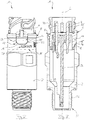
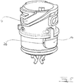
- FIGS. 1 . 2 show a magnetic field sensor 1 with a sensor element housing part 2 (see FIG. 4 ) and a terminal housing part 4 (see FIG FIG. 5 ) having device housing 6.
- the sensor element housing part 2 and the connector housing part 4 together form the device housing 6.
- the terminal housing part 4 and the sensor element housing part 2 are connected by means of a flange 8.
- connection element housing part 4 is arranged in the direction of a longitudinal axis L of the device housing 6 partially in the sensor element housing part 2.
- the longitudinal axis L of the device housing 6 is also the longitudinal axis L of the magnetic field sensor 1.
- the magnetic field sensor 1 is rod-shaped and cylindrical.
- a device housing outside of the device housing 6 has a toothing 10 of the connection element housing part 4 with the sensor element housing part 2 having toothing region 12.
- a toothed section 14 of the terminal housing part 4 and a toothed section 16 of the sensor element housing part 2 engage with one another and form the outside of the device housing.
- a seal 18 securing the connection of connection element housing part 4 and sensor element housing part 2 is arranged on the connection element housing part 4 and the sensor element housing part 2.
- the seal 18 in the illustrations after FIGS. 1 . 2 shown dashed and transparent.
- the seal 18 has a first code 20 which is an optical number code and a second code 22 which is an optical character code.
- the toothed region 12 with the seal 18, starting from the connection element housing part 4 is arranged after the curl 8.
- the toothing region 12 with the seal 18 is thus between the flange 8 and the engagement element 23rd arranged.
- the engagement element 23 is part of the sensor element housing part 2 in this embodiment.
- the toothed section 16 of the sensor element housing part 2 has a recess 24 in the sensor element housing part 2.
- the toothed section 14 of the connector housing part 4 has a projection 26 on the connector housing part 4. The projection 26 of the toothed section 14 of the connecting element housing part 4 engages positively in the recess 24 of the toothed section 16 of the sensor element housing part 2 (see FIG FIG. 1 ).
- the flange 8 runs around the device housing 6 on the outside of the device housing.
- the flange 8 has a crimping interruption 28. Furthermore, in particular from the FIGS. 1 . 2, 3 to recognize that the outside of the device housing in the toothed region 12 has a flakeless surface.
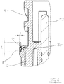
- FIG. 6 is a flared 8 comprehensive enlarged section of the magnetic field sensor 1 in a sectional view.
- the sensor element housing part 2 which in this embodiment consists of an aluminum alloy, has a wall thickness d which, for example, is 0.7 mm (tolerance, for example, ⁇ 0.1 mm).
- the flange 8 itself has a radius r, for example, 1.2 mm (tolerance, for example, ⁇ 0.2 mm).
- the flange 8 has an end edge of the sensor element housing part 2, which is flanged around a bead contour 30, which is a collar here, of the connection element housing part 4.
- the edge of the sensor element housing part 2 flanged around the flanged contour 30 has a height h, which, for example, is 2.5 mm (tolerance, for example, ⁇ 0.25 mm) before the flanging 8 is produced when the magnetic field sensor 1 is produced.
- An outer diameter of the magnetic field sensor 1 in the region of the flange in this embodiment is 26.5 mm.
- connection element housing part 4 consists in this embodiment of a plastic material and is a plastic injection molded component.
- the plastic material of the connector housing part 4 has safety pigments, not shown here.
- the plug socket has the connection contacts 32, 32 'and the connection element housing part 4.
- the printed circuit board 34 carries in this embodiment, a sensor element, not shown here, for example, a Hall element.
- the sensor element is arranged in a sensor head 36 of the magnetic field sensor 1, which magnetic field sensor 1 can also be referred to as an inductive sensor.
- the sensor head 36 is provided with an external thread 38.
- the magnetic field sensor 1 is screwed, for example, in a transmission housing of a transmission of a motor vehicle.
Landscapes
- Physics & Mathematics (AREA)
- General Physics & Mathematics (AREA)
- Condensed Matter Physics & Semiconductors (AREA)
- Transmission And Conversion Of Sensor Element Output (AREA)
Abstract
Description
- Die Erfindung bezieht sich auf einen Magnetfeldsensor mit einem zumindest ein Sensorelementgehäuseteil und ein Anschlusselementgehäuseteil aufweisenden Gerätegehäuse, wobei das Anschlusselementgehäuseteil in Richtung einer Längsachse des Gerätegehäuses zumindest teilweise in dem Sensorelementgehäuseteil angeordnet ist und wobei das Anschlusselementgehäuseteil und das Sensorelementgehäuseteil mittels einer Bördelung verbunden sind.
- Ein solcher Magnetfeldsensor ist zum Beispiel als sogenannter Geschwindigkeitsgeber oder Drehwertgeber für einen Fahrtschreiber in einem Kraftfahrzeug, insbesondere Nutzfahrzeug, bekannt. Der Magnetfeldsensor weist einen Sensorkopf auf und wird in ein Getriebegehäuse eines Getriebes des Kraftfahrzeugs eingeschraubt. Mittels des Sensorkopfes erfasst der Magnetfeldsensor eine Bewegung eines Getriebezahnrades des Getriebes. Die Bewegung des Getriebezahnrades ist ein Maß für die Geschwindigkeit des Kraftfahrzeugs. Ein Teil des Sensorelementgehäuseteils ist Bestandteil des Sensorkopfes. Über einen das Anschlusselementgehäuseteil und Anschlusskontakte umfassenden Steckersockel wird der Magnetfeldsensor mit dem Fahrtschreiber des Kraftfahrzeugs verbunden. Aufgrund der erforderlichen hohen Zuverlässigkeit von mit dem Fahrtschreiber aufgezeichneten Daten ist es unter anderem von Bedeutung, eine Manipulation des Magnetfeldsensors und aus einer solchen Manipulation folgende Datenverfälschungen zu vermeiden.
- Aufgabe der Erfindung ist es, einen Magnetfeldsensor der eingangs genannten Art zu schaffen, der eine hohe Manipulationssicherheit aufweist.
- Diese Aufgabe wird erfindungsgemäß dadurch gelöst, dass eine Gerätegehäuseaußenseite des Gerätegehäuses einen eine Verzahnung des Anschlusselementgehäuseteils mit dem Sensorelementgehäuseteil aufweisenden Verzahnungsbereich aufweist, wobei in dem Verzahnungsbereich ein Verzahnungsabschnitt des Anschlusselementgehäuseteils und ein Verzahnungsabschnitt des Sensorelementgehäuseteils ineinandergreifen und die Gerätegehäuseaußenseite bilden und wobei in dem Verzahnungsbereich an der Gerätegehäuseaußenseite ein die Verbindung von Anschlusselementgehäuseteil und Sensorelementgehäuseteil sicherndes Siegel auf dem Anschlusselementgehäuseteil und dem Sensorelementgehäuseteil angeordnet ist.
- Von besonderem Vorteil ist bei dem erfindungsgemäßen Magnetfeldsensor das gleichzeitige Vorsehen einer Verzahnung der beiden Gehäuseteile Sensorelementgehäuseteil und Anschlusselementgehäuseteil sowie eines in dem die Verzahnung aufweisenden Verzahnungsbereich angeordneten, die Verbindung der beiden Gehäuseteile sichernden Siegels. Ein unzulässiges Trennen von Sensorelementgehäuseteil und Anschlusselementgehäuseteil, das zum Beispiel in manipulativer Absicht vorgenommen werden könnte, um an das Innere des Magnetfeldsensors zu gelangen, kann somit besonders zuverlässig erkennbar gemacht werden, da das Trennen nicht nur zu einem Öffnen, insbesondere zu einem Aufbiegen, der Bördelung führt, sondern auch ein Ablösen des Siegels und/oder dessen Zerstörung erforderlich macht. Manipulationen sind somit besonders zuverlässig erkennbar. Die Verzahnung des Anschlusselementgehäuseteils mit dem Sensorelementgehäuseteil bildet zudem eine Verdrehsicherung der beiden genannten Gehäuseteile zueinander, wodurch eine hohe Torsionsfestigkeit erreicht wird.
- Das Siegel ist vorzugsweise mittels einer Klebung auf der Gerätegehäuseaußenseite angeordnet, das heißt das Siegel ist vorzugsweise auf das Gerätegehäuse in dem Verzahnungsbereich aufgeklebt. Das Siegel kann beispielsweise ein Siegel sein, welches bei einem Trennen von Sensorelementgehäuseteil und Anschlusselementgehäuseteil zerstört wird. Das Siegel kann beispielsweise ein sogenanntes VOID-Siegel sein, das bei einem Entfernen, zum Beispiel Ablösen oder Abreißen, des Siegels von dem Gerätegehäuse einen Schriftzug auf der Gerätegehäuseaußenseite sowie in oder auf dem Siegel selbst hinterlässt.
- Die Bördelung entsteht bei einer Herstellung des Magnetfeldsensors vorzugsweise dadurch, dass ein dünnwandiger Ringbereich an dem Sensorelementgehäuseteil über einen Kragen an dem Anschlusselementgehäuseteil umgebogen, nämlich umgebördelt, wird. Vorzugsweise ist das Material für das Sensorelementgehäuseteil derart ausgebildet, dass es ein mehrmaliges Auf- und Zusammenbiegen, wie es beispielsweise bei einem Öffnen und Schließen der Bördelung erfolgen würde, nicht zulässt. Weiter vorzugsweise ist das Material derart ausgebildet, dass es bereits bei einem einmaligen Öffnen der Bördelung zu sichtbaren Brüchen in dem Material kommt. Ergänzend oder alternativ ist das Material derart ausgebildet, dass (beispielsweise durch Strecken des Materials beim Öffnen der Bördelung) ein erneutes Zusammenbiegen, das heißt ein erneutes Schließen der Bördelung, nach einem Öffnen der Bördelung nicht mit dem Ergebnis einer optisch einwandfreien Bördelung möglich ist. Das Material für das Sensorelementgehäuseteil ist vorzugsweise ein sehr sprödes, hochfestes Material.
- Die Längsachse des Gerätegehäuses ist diejenige Achse des Gerätegehäuses, die der Richtung seiner größten Ausdehnung entspricht. Die Längsachse des Gerätegehäuses ist vorzugsweise auch die Längsachse des Magnetfeldsensors. Das Gerätegehäuse des Magnetfeldsensors kann insbesondere zylindrisch ausgebildet sein. Dann ergibt sich ein zylindrischer Magnetfeldsensor. Vorzugsweise ist der Magnetfeldsensor stabförmig.
- Zusätzliche vorteilhafte Weiterbildungen der Erfindung sind in den Unteransprüchen angegeben.
- Gemäß einer vorteilhaften Weiterbildung der Erfindung weist der Verzahnungsabschnitt des Sensorelementgehäuseteils eine Ausnehmung in dem Sensorelementgehäuseteil und der Verzahnungsabschnitt des Anschlusselementgehäuseteils einen Vorsprung an dem Anschlusselementgehäuseteil auf, und der Verzahnungsabschnitt des Anschlusselementgehäuseteils greift in den Verzahnungsabschnitt des Sensorelementgehäuseteils formschlüssig ein. Auf diese Weise wird eine einfach gestaltete, zugleich jedoch sehr zuverlässige und bei einer Herstellung des Magnetfeldsensors problemlos und aufgrund des Formschlusses präzise zu fügende und stabile Verbindung von Sensorelementgehäuseteil und Anschlusselementgehäuseteil erreicht.
- Einer anderen vorteilhaften Weiterbildung der Erfindung gemäß läuft die Bördelung an der Gerätegehäuseaußenseite um das Gerätegehäuse um und weist an dem Verzahnungsabschnitt des Anschlusselementgehäuseteils eine Bördelungsunterbrechung auf. Die Bördelung läuft somit bis auf die Unterbrechung der Bördelung an dem Verzahnungsabschnitt des Anschlusselementgehäuseteils um den Umfang des Gerätegehäuses um. Beispielsweise im Falle eines zylindrischen Gerätegehäuses läuft die Bördelung dann ringförmig um den Umfang des Gerätegehäuses um, wobei der Ring nicht geschlossen ist, sondern die Unterbrechung an dem Verzahnungsabschnitt des Anschlusselementgehäuseteils aufweist. Gegenüber einer grundsätzlich denkbaren Ausbildung der Bördelung als geschlossene Bördelung, zum Beispiel geschlossener Ring, ohne Bördelungsunterbrechung kann mit der vorerwähnten Weiterbildung der Erfindung das Anschlusselementgehäuseteil vorteilhaft frei in das Sensorelementgehäuseteil eingeschoben werden, wodurch die Herstellung des Magnetfeldsensors zusätzlich vereinfacht wird.
- Es wäre denkbar, dass der Verzahnungsbereich an seiner nach außen weisen Oberfläche zum Beispiel eine dreidimensionale Gestaltung aufweist. Hingegen weist einer vorteilhaften Weiterbildung der Erfindung gemäß die Gerätegehäuseaußenseite in dem Verzahnungsbereich eine absatzlose Oberfläche auf. Somit weist die Oberfläche, auf der das Siegel angeordnet ist, keine Stufen oder Absätze auf. Dadurch lässt sich das Siegel bei der Herstellung des Magnetfeldsensors besonders zuverlässig und mit großer Dauerhaltbarkeit auf der Gerätegehäuseaußenseite in dem Verzahnungsbereich anbringen.
- Das Sensorelementgehäuseteil kann beispielsweise ein Metallbauteil sein. Als besonders vorteilhaft hat es sich erwiesen, wenn einer Weiterbildung der Erfindung entsprechend das Sensorelementgehäuseteil zumindest im Bereich der Bördelung aus einer Aluminiumlegierung besteht. Die Aluminiumlegierung kann insbesondere AlZnMgCu1,5 (zum Beispiel EN AW-7075 T6) oder AlMgSiBi (zum Beispiel EN AW-6026 T6) sein. Die beiden vorgenannten Aluminiumlegierungen haben sich bei Versuchen als besonders geeignet für die Erfindung herausgestellt. Vorzugsweise besteht das Sensorelementgehäuseteil insgesamt aus der Aluminiumlegierung. Durch die Verwendung der Aluminiumlegierung kann ein zumindest teilweises Brechen des Sensorelementgehäuseteils im Bereich der Bördelung bei einem manipulativen Auseinanderziehen von Sensorelementgehäuseteil und Anschlusselementgehäuseteil des Magnetfeldsensors erreicht und so eine Manipulation des Magnetfeldsensors besonders gut erkennbar gemacht werden.
- Gemäß einer anderen vorteilhaften Weiterbildung der Erfindung weist das Sensorelementgehäuseteil im Bereich der Bördelung eine Wanddicke von 0,5 mm bis 0,9 mm, vorzugsweise 0,7 mm, auf, wobei die Toleranz beispielsweise ±0,1 mm beträgt. Damit kann einerseits eine hohe Stabilität der Verbindung von Sensorelementgehäuseteil und Anschlusselementgehäuseteil und andererseits eine irreversible Veränderung oder Zerstörung der Bördelung im Falle eines manipulativen Auseinanderziehens von Sensorelementgehäuseteil und Anschlusselementgehäuseteil des Magnetfeldsensors erreicht werden.
- Gleiches gilt, wenn gemäß einer anderen vorteilhaften Weiterbildung der Erfindung entsprechend die Bördelung einen Radius von 0,9 mm bis 1,5 mm, vorzugsweise 1,2 mm, aufweist, wobei die Toleranz beispielsweise ±0,2 mm beträgt. Ein Außendurchmesser des Magnetfeldsensors im Bereich der Bördelung beträgt beispielsweise 26,5 mm.
- Das Anschlusselementgehäuseteil kann vorteilhaft kostengünstig hergestellt werden, und gegebenenfalls in das Anschlusselementgehäuseteil eingebettete Anschlusskontakte können zudem auf einfache Weise voneinander elektrisch isoliert werden, wenn gemäß einer vorteilhaften Weiterbildung der Erfindung das Anschlusselementgehäuseteil aus einem Kunststoffmaterial besteht. Vorzugsweise ist das Anschlusselementgehäuseteil ein Kunststoffspritzgussbauteil, das heißt es ist in einem Kunststoffspritzgussverfahren hergestellt.
- Gemäß einer vorteilhaften Weiterbildung der Erfindung weist das Kunststoffmaterial des Anschlusselementgehäuseteils Sicherheitspigmente auf. Sicherheitspigmente sind Pigmente gegen Fälschungen. Die Sicherheitspigmente sind in dem Kunststoffmaterial unlöslich eingebettet. Das Vorhandensein der Sicherheitspigmente und gegebenenfalls deren Verteilung in dem Kunststoffmaterial kann beispielsweise optisch, gegebenenfalls unter Zuhilfenahme besonderer technischer Vorrichtungen oder Einrichtungen, erfasst werden. Dadurch wird vorteilhaft ein Schutz des Magnetfeldsensors vor Manipulationen weiter erhöht. Derartige Manipulationen könnten beispielsweise darin bestehen, dass ein bei einem unzulässigen Öffnen des Magnetfeldsensors beschädigtes Anschlusselementgehäuseteil durch ein in seiner Gestalt identisches Anschlusselementgehäuseteil ersetzt wird, welches jedoch keine Sicherheitspigmente aufweist. Beispielsweise können sowohl eine Art einer Verteilung der Sicherheitspigmente in dem Anschlusselementgehäuseteil als auch physikalische Eigenschaften der Sicherheitspigmente als Sicherheitsmerkmale zu einem Schutz vor Manipulationen dienen.
- Gemäß einer vorteilhaften Weiterbildung der Erfindung sind die Sicherheitspigmente derart ausgebildet, dass sie bei einer Bestrahlung mit Licht einer bestimmten Wellenlänge zu einem Leuchten angeregt werden. Damit kann eine besonders einfache Überprüfbarkeit auf mögliche Manipulationen erreicht werden. Vorzugsweise können die Sicherheitspigmente derart ausgebildet sein, dass sie bei der Bestrahlung zu einem für das menschliche Auge sichtbaren Leuchten angeregt werden. Insbesondere können die Sicherheitspigmente derart ausgebildet sein, dass sie bei Bestrahlung mit UV-Licht zu einem Leuchten angeregt werden.
- Ein Ausführungsbeispiel der Erfindung ist in der Zeichnung skizzenhaft und schematisiert dargestellt und wird im Folgenden näher beschrieben. Es zeigen
- Figur 1
- einen Magnetfeldsensor in einer perspektivischen Ansicht,
- Figur 2
- den Magnetfeldsensor nach
Figur 1 in einer Seitenansicht, - Figur 3
- den Magnetfeldsensor nach
Figur 1 in einer Schnittansicht, - Figur 4
- ein Sensorelementgehäuseteil des Magnetfeldsensors nach
Figur 1 in einer perspektivischen Ansicht, - Figur 5
- ein Anschlusselementgehäuseteil des Magnetfeldsensors nach
Figur 1 in perspektivischer Ansicht und - Figur 6
- einen vergrößerten Ausschnitt des Magnetfeldsensors nach
Figur 1 in einer Schnittansicht. - Sich jeweils entsprechende Elemente sind in allen Figuren mit gleichen Bezugszeichen versehen.
-
Figuren 1 ,2 zeigen einen Magnetfeldsensor 1 mit einem ein Sensorelementgehäuseteil 2 (vergleicheFigur 4 ) und ein Anschlusselementgehäuseteil 4 (vergleicheFigur 5 ) aufweisenden Gerätegehäuse 6. Das Sensorelementgehäuseteil 2 und das Anschlusselementgehäuseteil 4 bilden gemeinsam das Gerätegehäuse 6. Das Anschlusselementgehäuseteil 4 und das Sensorelementgehäuseteil 2 sind mittels einer Bördelung 8 verbunden. - Wie insbesondere aus
Figur 3 deutlich wird, ist das Anschlusselementgehäuseteil 4 in Richtung einer Längsachse L des Gerätegehäuses 6 teilweise in dem Sensorelementgehäuseteil 2 angeordnet. Die Längsachse L des Gerätegehäuses 6 ist auch die Längsachse L des Magnetfeldsensors 1. Der Magnetfeldsensor 1 ist stabförmig und zylindrisch ausgebildet. - Eine Gerätegehäuseaußenseite des Gerätegehäuses 6 weist einen eine Verzahnung 10 des Anschlusselementgehäuseteils 4 mit dem Sensorelementgehäuseteil 2 aufweisenden Verzahnungsbereich 12 auf. In dem Verzahnungsbereich 12 greifen ein Verzahnungsabschnitt 14 des Anschlusselementgehäuseteils 4 und ein Verzahnungsabschnitt 16 des Sensorelementgehäuseteils 2 ineinander und bilden die Gerätegehäuseaußenseite.
- Außerdem ist in dem Verzahnungsbereich 12 an der Gerätegehäuseaußenseite ein die Verbindung von Anschlusselementgehäuseteil 4 und Sensorelementgehäuseteil 2 sicherndes Siegel 18 auf dem Anschlusselementgehäuseteil 4 und dem Sensorelementgehäuseteil 2 angeordnet. Zur besseren Erkennbarkeit ist das Siegel 18 in den Darstellungen nach
Figuren 1 ,2 gestrichelt und durchsichtig gezeigt. In diesem Ausführungsbeispiel weist das Siegel 18 einen ersten Code 20, der ein optischer Zahlencode ist, und einen zweiten Code 22, der ein optischer Zeichencode ist, auf. - In Richtung der Längsachse L des Gerätegehäuses 6 ist der Verzahnungsbereich 12 mit dem Siegel 18, ausgehend von dem Anschlusselementgehäuseteil 4, nach der Bördelung 8 angeordnet. An den Verzahnungsbereich 12 mit dem Siegel 18 anschließend befindet sich ein Angriffselement 23 für ein Ansetzen eines Befestigungswerkzeugs zu einem Befestigen des Magnetfeldsensors 1 zum Beispiel an einem Getriebegehäuse eines Getriebes eines Kraftfahrzeugs. Der Verzahnungsbereich 12 mit dem Siegel 18 ist somit zwischen der Bördelung 8 und dem Angriffselement 23 angeordnet. Das Angriffselement 23 ist in diesem Ausführungsbeispiel Bestandteil des Sensorelementgehäuseteils 2.
- Es ist weiterhin zu erkennen, dass der Verzahnungsabschnitt 16 des Sensorelementgehäuseteils 2 eine Ausnehmung 24 in dem Sensorelementgehäuseteil 2 aufweist. Korrespondierend mit der Ausnehmung 24 weist der Verzahnungsabschnitt 14 des Anschlusselementgehäuseteils 4 einen Vorsprung 26 an dem Anschlusselementgehäuseteil 4 auf. Der Vorsprung 26 des Verzahnungsabschnitts 14 des Anschlusselementgehäuseteils 4 greift formschlüssig in die Ausnehmung 24 des Verzahnungsabschnitts 16 des Sensorelementgehäuseteils 2 ein (vergleiche
Figur 1 ). - Die Bördelung 8 läuft an der Gerätegehäuseaußenseite um das Gerätegehäuse 6 um. An dem Verzahnungsabschnitt 14 des Anschlusselementgehäuseteils 4 weist die Bördelung 8 eine Bördelungsunterbrechung 28 auf. Ferner ist insbesondere aus den
Figuren 1 ,2, 3 zu erkennen, dass die Gerätegehäuseaußenseite in dem Verzahnungsbereich 12 eine absatzlose Oberfläche aufweist. - In
Figur 6 ist ein die Bördelung 8 umfassender vergrößerter Ausschnitt des Magnetfeldsensors 1 in einer Schnittansicht gezeigt. Im Bereich der Bördelung 8 weist das Sensorelementgehäuseteil 2, das in diesem Ausführungsbeispiel aus einer Aluminiumlegierung besteht, eine Wanddicke d auf, die beispielsweise 0,7 mm (Toleranz zum Beispiel ±0,1 mm) beträgt. Die Bördelung 8 selbst weist einen Radius r auf, der beispielsweise 1,2 mm (Toleranz zum Beispiel ±0,2 mm) beträgt. - Die Bördelung 8 weist einen endseitigen Rand des Sensorelementgehäuseteils 2 auf, der um eine Bördelkontur 30, die hier ein Kragen ist, des Anschlusselementgehäuseteils 4 umgebördelt ist. Der um die Bördelkontur 30 umgebördelte Rand des Sensorelementgehäuseteils 2 weist vor einem Erzeugen der Bördelung 8 bei einem Herstellen des Magnetfeldsensors 1 eine Höhe h auf, die beispielsweise 2,5 mm (Toleranz zum Beispiel ±0,25 mm) beträgt.
- Ein Außendurchmesser des Magnetfeldsensors 1 beträgt im Bereich der Bördelung in diesem Ausführungsbeispiel 26,5 mm.
- Das Anschlusselementgehäuseteil 4 besteht in diesem Ausführungsbeispiel aus einem Kunststoffmaterial und ist ein Kunststoffspritzgussbauteil. Das Kunststoffmaterial des Anschlusselementgehäuseteils 4 weist hier nicht dargestellte Sicherheitspigmente auf.
- In das Anschlusselementgehäuseteil 4 sind elektrische Anschlusskontakte 32, 32' eingespritzt, so dass das Anschlusselementgehäuseteil 4 mit den Anschlusskontakten 32, 32' einen Steckersockel zur Verbindung des Magnetfeldsensors 1 mit beispielsweise einem Fahrtschreiber eines Kraftfahrzeugs bildet. Der Steckersockel weist die Anschlusskontakte 32, 32' und das Anschlusselementgehäuseteil 4 auf. Die Anschlusskontakte 32, 32' sind in nicht dargestellter Weise mit einer Leiterplatte 34 (siehe
Figur 3 ) elektrisch verbunden. Die Anschlusskontakte 32, 32' sind mit der Leiterplatte 34 zum Beispiel verlötet. - Die Leiterplatte 34 trägt in diesem Ausführungsbeispiel ein hier nicht dargestelltes Sensorelement, zum Beispiel ein Hall-Element. Das Sensorelement ist in einem Sensorkopf 36 des Magnetfeldsensors 1, welcher Magnetfeldsensor 1 auch als Induktivgeber bezeichnet werden kann, angeordnet.
- In diesem Ausführungsbeispiel ist der Sensorkopf 36 mit einem Außengewinde 38 versehen. Mittels des Außengewindes 38 wird der Magnetfeldsensor 1 beispielsweise in ein Getriebegehäuse eines Getriebes eines Kraftfahrzeugs eingeschraubt.
Claims (10)
- Magnetfeldsensor (1) mit einem zumindest ein Sensorelementgehäuseteil (2) und ein Anschlusselementgehäuseteil (4) aufweisenden Gerätegehäuse (6), wobei das Anschlusselementgehäuseteil (4) in Richtung einer Längsachse (L) des Gerätegehäuses (6) zumindest teilweise in dem Sensorelementgehäuseteil (2) angeordnet ist und wobei das Anschlusselementgehäuseteil (4) und das Sensorelementgehäuseteil (2) mittels einer Bördelung (8) verbunden sind, dadurch gekennzeichnet, dass eine Gerätegehäuseaußenseite des Gerätegehäuses (6) einen eine Verzahnung (10) des Anschlusselementgehäuseteils (4) mit dem Sensorelementgehäuseteil (2) aufweisenden Verzahnungsbereich (12) aufweist,
wobei in dem Verzahnungsbereich (12) ein Verzahnungsabschnitt (14) des Anschlusselementgehäuseteils (4) und ein Verzahnungsabschnitt (16) des Sensorelementgehäuseteils (2) ineinandergreifen und die Gerätegehäuseaußenseite bilden und
wobei in dem Verzahnungsbereich (12) an der Gerätegehäuseaußenseite ein die Verbindung von Anschlusselementgehäuseteil (4) und Sensorelementgehäuseteil (2) sicherndes Siegel (18) auf dem Anschlusselementgehäuseteil (4) und dem Sensorelementgehäuseteil (2) angeordnet ist. - Magnetfeldsensor nach Anspruch 1, dadurch gekennzeichnet, dass der Verzahnungsabschnitt (16) des Sensorelementgehäuseteils (2) eine Ausnehmung (24) in dem Sensorelementgehäuseteil (2) und der Verzahnungsabschnitt (14) des Anschlusselementgehäuseteils (4) einen Vorsprung (26) an dem Anschlusselementgehäuseteil (4) aufweist und dass der Verzahnungsabschnitt (14) des Anschlusselementgehäuseteils (4) in den Verzahnungsabschnitt (16) des Sensorelementgehäuseteils (2) formschlüssig eingreift.
- Magnetfeldsensor nach Anspruch 1 oder 2, dadurch gekennzeichnet, dass die Bördelung (8) an der Gerätegehäuseaußenseite um das Gerätegehäuse (6) umläuft und an dem Verzahnungsabschnitt (14) des Anschlusselementgehäuseteils (4) eine Bördelungsunterbrechung (28) aufweist.
- Magnetfeldsensor nach einem der vorhergehenden Ansprüche, dadurch gekennzeichnet, dass die Gerätegehäuseaußenseite in dem Verzahnungsbereich (12) eine absatzlose Oberfläche aufweist.
- Magnetfeldsensor nach einem der vorhergehenden Ansprüche, dadurch gekennzeichnet, dass das Sensorelementgehäuseteil (2) zumindest im Bereich der Bördelung (8) aus einer Aluminiumlegierung besteht.
- Magnetfeldsensor nach einem der vorhergehenden Ansprüche, dadurch gekennzeichnet, dass das Sensorelementgehäuseteil (2) im Bereich der Bördelung (8) eine Wanddicke (d) von 0,5 mm bis 0,9 mm aufweist.
- Magnetfeldsensor nach einem der vorhergehenden Ansprüche, dadurch gekennzeichnet, dass die Bördelung (8) einen Radius (r) von 0,9 mm bis 1,5 mm aufweist.
- Magnetfeldsensor nach einem der vorhergehenden Ansprüche, dadurch gekennzeichnet, dass das Anschlusselementgehäuseteil (4) aus einem Kunststoffmaterial besteht.
- Magnetfeldsensor nach Anspruch 8, dadurch gekennzeichnet, dass das Kunststoffmaterial des Anschlusselementgehäuseteils (4) Sicherheitspigmente aufweist.
- Magnetfeldsensor nach Anspruch 9, dadurch gekennzeichnet, dass die Sicherheitspigmente derart ausgebildet sind, dass sie bei einer Bestrahlung mit Licht einer bestimmten Wellenlänge zu einem Leuchten angeregt werden.
Applications Claiming Priority (1)
| Application Number | Priority Date | Filing Date | Title |
|---|---|---|---|
| DE102017213713.4A DE102017213713B4 (de) | 2017-08-07 | 2017-08-07 | Magnetfeldsensor |
Publications (2)
| Publication Number | Publication Date |
|---|---|
| EP3441778A1 true EP3441778A1 (de) | 2019-02-13 |
| EP3441778B1 EP3441778B1 (de) | 2020-08-05 |
Family
ID=62837584
Family Applications (1)
| Application Number | Title | Priority Date | Filing Date |
|---|---|---|---|
| EP18179518.8A Active EP3441778B1 (de) | 2017-08-07 | 2018-06-25 | Magnetfeldsensor |
Country Status (2)
| Country | Link |
|---|---|
| EP (1) | EP3441778B1 (de) |
| DE (1) | DE102017213713B4 (de) |
Cited By (3)
| Publication number | Priority date | Publication date | Assignee | Title |
|---|---|---|---|---|
| EP3767304A1 (de) * | 2019-07-17 | 2021-01-20 | Continental Automotive GmbH | Magnetfeldsensor |
| EP3865829A1 (de) * | 2020-02-17 | 2021-08-18 | Continental Automotive GmbH | Magnetfeldsensor mit einem gerätegehäuse |
| SE544357C2 (en) * | 2020-02-17 | 2022-04-19 | Continental Automotive Gmbh | Magnetic field sensor having a device housing |
Families Citing this family (1)
| Publication number | Priority date | Publication date | Assignee | Title |
|---|---|---|---|---|
| DE102020202668B4 (de) | 2020-03-02 | 2021-09-23 | Continental Automotive Gmbh | Magnetfeldsensor mit einer Markierung und Verfahren zur Herstellung eines Magnetfeldsensors |
Citations (4)
| Publication number | Priority date | Publication date | Assignee | Title |
|---|---|---|---|---|
| EP0298352A2 (de) * | 1987-07-07 | 1989-01-11 | Zeller Plastik GmbH | Originalitätssicherung |
| WO2015140089A1 (de) * | 2014-03-21 | 2015-09-24 | Continental Automotive Gmbh | Stabförmiger magnetfeldsensor |
| EP2958082A1 (de) * | 2014-06-06 | 2015-12-23 | Continental Automotive GmbH | Gehäuse zur abdeckung eines funktionselements mit einer zugangsbeschränkung |
| EP3130935A1 (de) * | 2015-08-11 | 2017-02-15 | Continental Automotive GmbH | Stabförmiger magnetfeldsensor |
Family Cites Families (5)
| Publication number | Priority date | Publication date | Assignee | Title |
|---|---|---|---|---|
| DE19546865C1 (de) * | 1995-12-15 | 1996-10-02 | Vdo Schindling | Montageverfahren für einen Magnetfeldgeber |
| US6392406B1 (en) * | 1999-12-06 | 2002-05-21 | Delphi Technologies, Inc. | Adjustable length vehicle speed sensor |
| DE102007032504B4 (de) * | 2007-07-12 | 2026-05-13 | Link Gmbh | Sensoreinrichtung zur berührungsfreien Identitäts- oder Positionsermittlung |
| DE102008025067B4 (de) * | 2008-05-26 | 2012-06-21 | Continental Automotive Gmbh | Plombenanordnung |
| CN112964891A (zh) * | 2013-12-24 | 2021-06-15 | 博世汽车部件(苏州)有限公司 | 模块化速度传感器 |
-
2017
- 2017-08-07 DE DE102017213713.4A patent/DE102017213713B4/de not_active Expired - Fee Related
-
2018
- 2018-06-25 EP EP18179518.8A patent/EP3441778B1/de active Active
Patent Citations (4)
| Publication number | Priority date | Publication date | Assignee | Title |
|---|---|---|---|---|
| EP0298352A2 (de) * | 1987-07-07 | 1989-01-11 | Zeller Plastik GmbH | Originalitätssicherung |
| WO2015140089A1 (de) * | 2014-03-21 | 2015-09-24 | Continental Automotive Gmbh | Stabförmiger magnetfeldsensor |
| EP2958082A1 (de) * | 2014-06-06 | 2015-12-23 | Continental Automotive GmbH | Gehäuse zur abdeckung eines funktionselements mit einer zugangsbeschränkung |
| EP3130935A1 (de) * | 2015-08-11 | 2017-02-15 | Continental Automotive GmbH | Stabförmiger magnetfeldsensor |
Cited By (3)
| Publication number | Priority date | Publication date | Assignee | Title |
|---|---|---|---|---|
| EP3767304A1 (de) * | 2019-07-17 | 2021-01-20 | Continental Automotive GmbH | Magnetfeldsensor |
| EP3865829A1 (de) * | 2020-02-17 | 2021-08-18 | Continental Automotive GmbH | Magnetfeldsensor mit einem gerätegehäuse |
| SE544357C2 (en) * | 2020-02-17 | 2022-04-19 | Continental Automotive Gmbh | Magnetic field sensor having a device housing |
Also Published As
| Publication number | Publication date |
|---|---|
| EP3441778B1 (de) | 2020-08-05 |
| DE102017213713B4 (de) | 2019-06-19 |
| DE102017213713A1 (de) | 2019-02-07 |
Similar Documents
| Publication | Publication Date | Title |
|---|---|---|
| EP3441778B1 (de) | Magnetfeldsensor | |
| DE19621762A1 (de) | Elektrische Verbinderanordnung mit Verbinderpositions-Gewährleistungseinrichtung | |
| DE102008036399A1 (de) | Datenkabel | |
| DE4122374A1 (de) | Schluesselvorrichtung | |
| DE69105096T2 (de) | Deckelmodul für eine luftsackvorrichtung. | |
| EP2638603A1 (de) | Abdichtung der kontaktkammern gegen spritzmaterial (kunststoff) während dem umspritzprozess | |
| EP2190073A1 (de) | Steckverbindervorrichtung | |
| EP1513721B1 (de) | Verschlussdeckel | |
| DE69310472T2 (de) | Schnappverbinder für optische Fasern mit umgossenem Steckerkörper | |
| DE2043960A1 (de) | Turverriegelungseinnchtung Ausscheidung aus 2005814 | |
| EP3323585B1 (de) | Beleuchtungseinrichtung für ein kraftfahrzeug | |
| DE1540212A1 (de) | Elektrische Steckverbindung | |
| EP3114739B1 (de) | Vorrichtung zum einziehen von kabeln | |
| DE4301506A1 (de) | Steckdose für eine Steckverbindung für den elektrischen Anschluß von Kraftfahrzeuganhängern an Kraftfahrzeugen | |
| DE2919483A1 (de) | Schlossriegel | |
| DE102020201959B4 (de) | Magnetfeldsensor mit einem Gerätegehäuse | |
| EP1437461B1 (de) | Verfahren zur Herstellung einer Türschlossvorrichtung für ein Kraftfahrzeug sowie eine durch ein derartiges Verfahren hergestellte Türschlossvorrichtung | |
| DE102020212977A1 (de) | Sicherheitselement mit Fensterausleger und Verfahren zur Herstellung | |
| DE8811133U1 (de) | Induktiver Annäherungsdetektor | |
| EP4345354B1 (de) | Steckverbinder zum verbinden von leitungen für flüssige oder gasförmige medien, sowie ein verfahren zum herstellen einer steckverbindung zwischen dem steckverbinder und einem gegensteckverbinder | |
| EP3767304B1 (de) | Magnetfeldsensor | |
| EP1380478B1 (de) | Einbruchsicherung und Verfahren zu deren Herstellung | |
| EP0428936A1 (de) | Kindersicherung für Steckdosen | |
| DE202013101939U1 (de) | Teil-massiver Hohlstift | |
| DE29608196U1 (de) | Schloßvorrichtung für Motorradscheibenbremsen |
Legal Events
| Date | Code | Title | Description |
|---|---|---|---|
| PUAI | Public reference made under article 153(3) epc to a published international application that has entered the european phase |
Free format text: ORIGINAL CODE: 0009012 |
|
| STAA | Information on the status of an ep patent application or granted ep patent |
Free format text: STATUS: THE APPLICATION HAS BEEN PUBLISHED |
|
| AK | Designated contracting states |
Kind code of ref document: A1 Designated state(s): AL AT BE BG CH CY CZ DE DK EE ES FI FR GB GR HR HU IE IS IT LI LT LU LV MC MK MT NL NO PL PT RO RS SE SI SK SM TR |
|
| AX | Request for extension of the european patent |
Extension state: BA ME |
|
| STAA | Information on the status of an ep patent application or granted ep patent |
Free format text: STATUS: REQUEST FOR EXAMINATION WAS MADE |
|
| 17P | Request for examination filed |
Effective date: 20190813 |
|
| RBV | Designated contracting states (corrected) |
Designated state(s): AL AT BE BG CH CY CZ DE DK EE ES FI FR GB GR HR HU IE IS IT LI LT LU LV MC MK MT NL NO PL PT RO RS SE SI SK SM TR |
|
| GRAP | Despatch of communication of intention to grant a patent |
Free format text: ORIGINAL CODE: EPIDOSNIGR1 |
|
| STAA | Information on the status of an ep patent application or granted ep patent |
Free format text: STATUS: GRANT OF PATENT IS INTENDED |
|
| INTG | Intention to grant announced |
Effective date: 20200131 |
|
| GRAS | Grant fee paid |
Free format text: ORIGINAL CODE: EPIDOSNIGR3 |
|
| GRAA | (expected) grant |
Free format text: ORIGINAL CODE: 0009210 |
|
| STAA | Information on the status of an ep patent application or granted ep patent |
Free format text: STATUS: THE PATENT HAS BEEN GRANTED |
|
| AK | Designated contracting states |
Kind code of ref document: B1 Designated state(s): AL AT BE BG CH CY CZ DE DK EE ES FI FR GB GR HR HU IE IS IT LI LT LU LV MC MK MT NL NO PL PT RO RS SE SI SK SM TR |
|
| REG | Reference to a national code |
Ref country code: GB Ref legal event code: FG4D Free format text: NOT ENGLISH |
|
| REG | Reference to a national code |
Ref country code: CH Ref legal event code: EP |
|
| REG | Reference to a national code |
Ref country code: AT Ref legal event code: REF Ref document number: 1299469 Country of ref document: AT Kind code of ref document: T Effective date: 20200815 |
|
| REG | Reference to a national code |
Ref country code: DE Ref legal event code: R096 Ref document number: 502018002093 Country of ref document: DE |
|
| REG | Reference to a national code |
Ref country code: IE Ref legal event code: FG4D Free format text: LANGUAGE OF EP DOCUMENT: GERMAN |
|
| REG | Reference to a national code |
Ref country code: SE Ref legal event code: TRGR |
|
| REG | Reference to a national code |
Ref country code: LT Ref legal event code: MG4D |
|
| REG | Reference to a national code |
Ref country code: NL Ref legal event code: MP Effective date: 20200805 |
|
| PG25 | Lapsed in a contracting state [announced via postgrant information from national office to epo] |
Ref country code: BG Free format text: LAPSE BECAUSE OF FAILURE TO SUBMIT A TRANSLATION OF THE DESCRIPTION OR TO PAY THE FEE WITHIN THE PRESCRIBED TIME-LIMIT Effective date: 20201105 Ref country code: HR Free format text: LAPSE BECAUSE OF FAILURE TO SUBMIT A TRANSLATION OF THE DESCRIPTION OR TO PAY THE FEE WITHIN THE PRESCRIBED TIME-LIMIT Effective date: 20200805 Ref country code: NO Free format text: LAPSE BECAUSE OF FAILURE TO SUBMIT A TRANSLATION OF THE DESCRIPTION OR TO PAY THE FEE WITHIN THE PRESCRIBED TIME-LIMIT Effective date: 20201105 Ref country code: LT Free format text: LAPSE BECAUSE OF FAILURE TO SUBMIT A TRANSLATION OF THE DESCRIPTION OR TO PAY THE FEE WITHIN THE PRESCRIBED TIME-LIMIT Effective date: 20200805 Ref country code: ES Free format text: LAPSE BECAUSE OF FAILURE TO SUBMIT A TRANSLATION OF THE DESCRIPTION OR TO PAY THE FEE WITHIN THE PRESCRIBED TIME-LIMIT Effective date: 20200805 Ref country code: GR Free format text: LAPSE BECAUSE OF FAILURE TO SUBMIT A TRANSLATION OF THE DESCRIPTION OR TO PAY THE FEE WITHIN THE PRESCRIBED TIME-LIMIT Effective date: 20201106 Ref country code: FI Free format text: LAPSE BECAUSE OF FAILURE TO SUBMIT A TRANSLATION OF THE DESCRIPTION OR TO PAY THE FEE WITHIN THE PRESCRIBED TIME-LIMIT Effective date: 20200805 Ref country code: PT Free format text: LAPSE BECAUSE OF FAILURE TO SUBMIT A TRANSLATION OF THE DESCRIPTION OR TO PAY THE FEE WITHIN THE PRESCRIBED TIME-LIMIT Effective date: 20201207 |
|
| PG25 | Lapsed in a contracting state [announced via postgrant information from national office to epo] |
Ref country code: LV Free format text: LAPSE BECAUSE OF FAILURE TO SUBMIT A TRANSLATION OF THE DESCRIPTION OR TO PAY THE FEE WITHIN THE PRESCRIBED TIME-LIMIT Effective date: 20200805 Ref country code: PL Free format text: LAPSE BECAUSE OF FAILURE TO SUBMIT A TRANSLATION OF THE DESCRIPTION OR TO PAY THE FEE WITHIN THE PRESCRIBED TIME-LIMIT Effective date: 20200805 Ref country code: RS Free format text: LAPSE BECAUSE OF FAILURE TO SUBMIT A TRANSLATION OF THE DESCRIPTION OR TO PAY THE FEE WITHIN THE PRESCRIBED TIME-LIMIT Effective date: 20200805 Ref country code: NL Free format text: LAPSE BECAUSE OF FAILURE TO SUBMIT A TRANSLATION OF THE DESCRIPTION OR TO PAY THE FEE WITHIN THE PRESCRIBED TIME-LIMIT Effective date: 20200805 Ref country code: IS Free format text: LAPSE BECAUSE OF FAILURE TO SUBMIT A TRANSLATION OF THE DESCRIPTION OR TO PAY THE FEE WITHIN THE PRESCRIBED TIME-LIMIT Effective date: 20201205 |
|
| PG25 | Lapsed in a contracting state [announced via postgrant information from national office to epo] |
Ref country code: DK Free format text: LAPSE BECAUSE OF FAILURE TO SUBMIT A TRANSLATION OF THE DESCRIPTION OR TO PAY THE FEE WITHIN THE PRESCRIBED TIME-LIMIT Effective date: 20200805 Ref country code: CZ Free format text: LAPSE BECAUSE OF FAILURE TO SUBMIT A TRANSLATION OF THE DESCRIPTION OR TO PAY THE FEE WITHIN THE PRESCRIBED TIME-LIMIT Effective date: 20200805 Ref country code: RO Free format text: LAPSE BECAUSE OF FAILURE TO SUBMIT A TRANSLATION OF THE DESCRIPTION OR TO PAY THE FEE WITHIN THE PRESCRIBED TIME-LIMIT Effective date: 20200805 Ref country code: EE Free format text: LAPSE BECAUSE OF FAILURE TO SUBMIT A TRANSLATION OF THE DESCRIPTION OR TO PAY THE FEE WITHIN THE PRESCRIBED TIME-LIMIT Effective date: 20200805 Ref country code: SM Free format text: LAPSE BECAUSE OF FAILURE TO SUBMIT A TRANSLATION OF THE DESCRIPTION OR TO PAY THE FEE WITHIN THE PRESCRIBED TIME-LIMIT Effective date: 20200805 |
|
| REG | Reference to a national code |
Ref country code: DE Ref legal event code: R097 Ref document number: 502018002093 Country of ref document: DE |
|
| PG25 | Lapsed in a contracting state [announced via postgrant information from national office to epo] |
Ref country code: AL Free format text: LAPSE BECAUSE OF FAILURE TO SUBMIT A TRANSLATION OF THE DESCRIPTION OR TO PAY THE FEE WITHIN THE PRESCRIBED TIME-LIMIT Effective date: 20200805 |
|
| PLBE | No opposition filed within time limit |
Free format text: ORIGINAL CODE: 0009261 |
|
| STAA | Information on the status of an ep patent application or granted ep patent |
Free format text: STATUS: NO OPPOSITION FILED WITHIN TIME LIMIT |
|
| PG25 | Lapsed in a contracting state [announced via postgrant information from national office to epo] |
Ref country code: SK Free format text: LAPSE BECAUSE OF FAILURE TO SUBMIT A TRANSLATION OF THE DESCRIPTION OR TO PAY THE FEE WITHIN THE PRESCRIBED TIME-LIMIT Effective date: 20200805 |
|
| 26N | No opposition filed |
Effective date: 20210507 |
|
| PG25 | Lapsed in a contracting state [announced via postgrant information from national office to epo] |
Ref country code: IT Free format text: LAPSE BECAUSE OF FAILURE TO SUBMIT A TRANSLATION OF THE DESCRIPTION OR TO PAY THE FEE WITHIN THE PRESCRIBED TIME-LIMIT Effective date: 20200805 |
|
| PG25 | Lapsed in a contracting state [announced via postgrant information from national office to epo] |
Ref country code: SI Free format text: LAPSE BECAUSE OF FAILURE TO SUBMIT A TRANSLATION OF THE DESCRIPTION OR TO PAY THE FEE WITHIN THE PRESCRIBED TIME-LIMIT Effective date: 20200805 |
|
| PG25 | Lapsed in a contracting state [announced via postgrant information from national office to epo] |
Ref country code: MC Free format text: LAPSE BECAUSE OF FAILURE TO SUBMIT A TRANSLATION OF THE DESCRIPTION OR TO PAY THE FEE WITHIN THE PRESCRIBED TIME-LIMIT Effective date: 20200805 |
|
| REG | Reference to a national code |
Ref country code: CH Ref legal event code: PL |
|
| REG | Reference to a national code |
Ref country code: BE Ref legal event code: MM Effective date: 20210630 |
|
| PG25 | Lapsed in a contracting state [announced via postgrant information from national office to epo] |
Ref country code: LU Free format text: LAPSE BECAUSE OF NON-PAYMENT OF DUE FEES Effective date: 20210625 |
|
| PG25 | Lapsed in a contracting state [announced via postgrant information from national office to epo] |
Ref country code: LI Free format text: LAPSE BECAUSE OF NON-PAYMENT OF DUE FEES Effective date: 20210630 Ref country code: IE Free format text: LAPSE BECAUSE OF NON-PAYMENT OF DUE FEES Effective date: 20210625 Ref country code: CH Free format text: LAPSE BECAUSE OF NON-PAYMENT OF DUE FEES Effective date: 20210630 |
|
| REG | Reference to a national code |
Ref country code: DE Ref legal event code: R081 Ref document number: 502018002093 Country of ref document: DE Owner name: CONTINENTAL AUTOMOTIVE TECHNOLOGIES GMBH, DE Free format text: FORMER OWNER: CONTINENTAL AUTOMOTIVE GMBH, 30165 HANNOVER, DE Ref country code: DE Ref legal event code: R081 Ref document number: 502018002093 Country of ref document: DE Owner name: AUMOVIO GERMANY GMBH, DE Free format text: FORMER OWNER: CONTINENTAL AUTOMOTIVE GMBH, 30165 HANNOVER, DE |
|
| PG25 | Lapsed in a contracting state [announced via postgrant information from national office to epo] |
Ref country code: BE Free format text: LAPSE BECAUSE OF NON-PAYMENT OF DUE FEES Effective date: 20210630 |
|
| GBPC | Gb: european patent ceased through non-payment of renewal fee |
Effective date: 20220625 |
|
| PG25 | Lapsed in a contracting state [announced via postgrant information from national office to epo] |
Ref country code: GB Free format text: LAPSE BECAUSE OF NON-PAYMENT OF DUE FEES Effective date: 20220625 |
|
| P01 | Opt-out of the competence of the unified patent court (upc) registered |
Effective date: 20230522 |
|
| PG25 | Lapsed in a contracting state [announced via postgrant information from national office to epo] |
Ref country code: CY Free format text: LAPSE BECAUSE OF FAILURE TO SUBMIT A TRANSLATION OF THE DESCRIPTION OR TO PAY THE FEE WITHIN THE PRESCRIBED TIME-LIMIT Effective date: 20200805 |
|
| PG25 | Lapsed in a contracting state [announced via postgrant information from national office to epo] |
Ref country code: HU Free format text: LAPSE BECAUSE OF FAILURE TO SUBMIT A TRANSLATION OF THE DESCRIPTION OR TO PAY THE FEE WITHIN THE PRESCRIBED TIME-LIMIT; INVALID AB INITIO Effective date: 20180625 |
|
| REG | Reference to a national code |
Ref country code: DE Ref legal event code: R081 Ref document number: 502018002093 Country of ref document: DE Owner name: CONTINENTAL AUTOMOTIVE TECHNOLOGIES GMBH, DE Free format text: FORMER OWNER: CONTINENTAL AUTOMOTIVE TECHNOLOGIES GMBH, 30165 HANNOVER, DE Ref country code: DE Ref legal event code: R081 Ref document number: 502018002093 Country of ref document: DE Owner name: AUMOVIO GERMANY GMBH, DE Free format text: FORMER OWNER: CONTINENTAL AUTOMOTIVE TECHNOLOGIES GMBH, 30165 HANNOVER, DE |
|
| PG25 | Lapsed in a contracting state [announced via postgrant information from national office to epo] |
Ref country code: MK Free format text: LAPSE BECAUSE OF FAILURE TO SUBMIT A TRANSLATION OF THE DESCRIPTION OR TO PAY THE FEE WITHIN THE PRESCRIBED TIME-LIMIT Effective date: 20200805 |
|
| PG25 | Lapsed in a contracting state [announced via postgrant information from national office to epo] |
Ref country code: TR Free format text: LAPSE BECAUSE OF FAILURE TO SUBMIT A TRANSLATION OF THE DESCRIPTION OR TO PAY THE FEE WITHIN THE PRESCRIBED TIME-LIMIT Effective date: 20200805 |
|
| REG | Reference to a national code |
Ref country code: AT Ref legal event code: MM01 Ref document number: 1299469 Country of ref document: AT Kind code of ref document: T Effective date: 20230625 |
|
| PG25 | Lapsed in a contracting state [announced via postgrant information from national office to epo] |
Ref country code: MT Free format text: LAPSE BECAUSE OF FAILURE TO SUBMIT A TRANSLATION OF THE DESCRIPTION OR TO PAY THE FEE WITHIN THE PRESCRIBED TIME-LIMIT Effective date: 20200805 |
|
| PG25 | Lapsed in a contracting state [announced via postgrant information from national office to epo] |
Ref country code: AT Free format text: LAPSE BECAUSE OF NON-PAYMENT OF DUE FEES Effective date: 20230625 |
|
| PG25 | Lapsed in a contracting state [announced via postgrant information from national office to epo] |
Ref country code: AT Free format text: LAPSE BECAUSE OF NON-PAYMENT OF DUE FEES Effective date: 20230625 |
|
| PGFP | Annual fee paid to national office [announced via postgrant information from national office to epo] |
Ref country code: DE Payment date: 20250630 Year of fee payment: 8 |
|
| PGFP | Annual fee paid to national office [announced via postgrant information from national office to epo] |
Ref country code: FR Payment date: 20250625 Year of fee payment: 8 |
|
| PGFP | Annual fee paid to national office [announced via postgrant information from national office to epo] |
Ref country code: SE Payment date: 20250618 Year of fee payment: 8 |
|
| REG | Reference to a national code |
Ref country code: DE Ref legal event code: R081 Ref document number: 502018002093 Country of ref document: DE Owner name: AUMOVIO GERMANY GMBH, DE Free format text: FORMER OWNER: CONTINENTAL AUTOMOTIVE TECHNOLOGIES GMBH, 30175 HANNOVER, DE |
|
| PGFP | Annual fee paid to national office [announced via postgrant information from national office to epo] |
Ref country code: AT Payment date: 20260410 Year of fee payment: 5 |