EP3441518A1 - Acoustic heat exchanger treatment for a laundry appliance having a heat pump system - Google Patents
Acoustic heat exchanger treatment for a laundry appliance having a heat pump system Download PDFInfo
- Publication number
- EP3441518A1 EP3441518A1 EP18185317.7A EP18185317A EP3441518A1 EP 3441518 A1 EP3441518 A1 EP 3441518A1 EP 18185317 A EP18185317 A EP 18185317A EP 3441518 A1 EP3441518 A1 EP 3441518A1
- Authority
- EP
- European Patent Office
- Prior art keywords
- insulating member
- heat exchanger
- laundry appliance
- evaporator
- process air
- Prior art date
- Legal status (The legal status is an assumption and is not a legal conclusion. Google has not performed a legal analysis and makes no representation as to the accuracy of the status listed.)
- Withdrawn
Links
Images




Classifications
-
- D—TEXTILES; PAPER
- D06—TREATMENT OF TEXTILES OR THE LIKE; LAUNDERING; FLEXIBLE MATERIALS NOT OTHERWISE PROVIDED FOR
- D06F—LAUNDERING, DRYING, IRONING, PRESSING OR FOLDING TEXTILE ARTICLES
- D06F58/00—Domestic laundry dryers
- D06F58/20—General details of domestic laundry dryers
- D06F58/206—Heat pump arrangements
-
- F—MECHANICAL ENGINEERING; LIGHTING; HEATING; WEAPONS; BLASTING
- F25—REFRIGERATION OR COOLING; COMBINED HEATING AND REFRIGERATION SYSTEMS; HEAT PUMP SYSTEMS; MANUFACTURE OR STORAGE OF ICE; LIQUEFACTION SOLIDIFICATION OF GASES
- F25B—REFRIGERATION MACHINES, PLANTS OR SYSTEMS; COMBINED HEATING AND REFRIGERATION SYSTEMS; HEAT PUMP SYSTEMS
- F25B30/00—Heat pumps
- F25B30/02—Heat pumps of the compression type
-
- F—MECHANICAL ENGINEERING; LIGHTING; HEATING; WEAPONS; BLASTING
- F25—REFRIGERATION OR COOLING; COMBINED HEATING AND REFRIGERATION SYSTEMS; HEAT PUMP SYSTEMS; MANUFACTURE OR STORAGE OF ICE; LIQUEFACTION SOLIDIFICATION OF GASES
- F25B—REFRIGERATION MACHINES, PLANTS OR SYSTEMS; COMBINED HEATING AND REFRIGERATION SYSTEMS; HEAT PUMP SYSTEMS
- F25B2500/00—Problems to be solved
- F25B2500/12—Sound
-
- F—MECHANICAL ENGINEERING; LIGHTING; HEATING; WEAPONS; BLASTING
- F25—REFRIGERATION OR COOLING; COMBINED HEATING AND REFRIGERATION SYSTEMS; HEAT PUMP SYSTEMS; MANUFACTURE OR STORAGE OF ICE; LIQUEFACTION SOLIDIFICATION OF GASES
- F25B—REFRIGERATION MACHINES, PLANTS OR SYSTEMS; COMBINED HEATING AND REFRIGERATION SYSTEMS; HEAT PUMP SYSTEMS
- F25B2500/00—Problems to be solved
- F25B2500/13—Vibrations
Definitions
- the device is in the field of laundry appliances, and more specifically, a laundry appliance having a heat pump system that includes a heat exchanger, where an acoustical treatment is applied to a surface of the heat exchanger for dampening vibration and noise.
- a laundry appliance in at least one aspect, includes a rotating drum for processing laundry.
- a heat pump system has a heat exchanger that is positioned within an air conditioning chamber.
- a blower directs process air through an air path that includes the rotating drum and the air conditioning chamber.
- An insulating member is positioned between a top portion of the heat exchanger and an underside of a cover member for the air conditioning chamber. The insulating member directs the process air through the heat exchanger and away from the underside of the cover member and absorbs sound and vibration generated by movement of process air through the heat exchanger.
- a heat exchange system for a heat pump appliance includes a blower that directs process air through an air path that includes a rotating drum.
- a heat pump system has an evaporator positioned within the air path for dehumidifying the process air, wherein a top portion of the evaporator is separated from an inside surface of the air path by a gap.
- An insulating member occupies the gap and engages the top portion of the evaporator and the inside surface of the air path, wherein the insulating member directs the process air away from the gap and into the evaporator.
- a heat exchange system for a heat pump appliance includes a blower that directs process air through an air path that includes a rotating drum and a heat exchange cavity.
- a heat pump system has an evaporator and a condenser positioned within the heat exchange cavity for dehumidifying and heating the process air, respectively.
- An acoustical damper is compressed within a gap defined between top surfaces of the evaporator and the condenser and an interior surface of the heat exchange cavity. The acoustical damper directs the process air away from the gap and into the evaporator and also absorbs sound generated by movement of the process air through the evaporator and the condenser.
- the terms "upper,” “lower,” “right,” “left,” “rear,” “front,” “vertical,” “horizontal,” and derivatives thereof shall relate to the device as oriented in FIG. 1 .
- the device may assume various alternative orientations and step sequences, except where expressly specified to the contrary.
- the specific devices and processes illustrated in the attached drawings, and described in the following specification are simply exemplary embodiments of the inventive concepts defined in the appended claims. Hence, specific dimensions and other physical characteristics relating to the embodiments disclosed herein are not to be considered as limiting, unless the claims expressly state otherwise.
- reference numeral 10 generally refers to a heat pump system that is incorporated within a laundry appliance 12.
- the heat pump system 10 is configured to treat process air 14 that is moved through the appliance 12 for processing laundry disposed within a rotating drum 16 of the appliance 12.
- Process air 14 is moved from the rotating drum 16 and typically carries lint particles 18 and moisture from the rotating drum 16 toward the various heat exchangers 20 of the heat pump system 10.
- the heat exchangers 20 treat the process air 14 to dehumidify and potentially heat the process air 14 to be returned to the rotating drum 16 to continue a particular drying operation.
- the laundry appliance 12 can include a rotating drum 16 for processing laundry.
- the heat pump system 10 includes the heat exchanger 20 that is positioned within an air conditioning chamber 22.
- a blower 24 is configured to direct process air 14 through an air path 26 that includes the rotating drum 16 and the air conditioning chamber 22.
- An insulating member 28 is positioned between a top portion 30 of the heat exchanger 20 and an underside 32 of a cover member 34 for the air conditioning chamber 22. The insulating member 28 is configured to direct the process air 14 through the heat exchanger 20 and away from the underside 32 of the cover member 34.
- the insulating member 28 occupies substantially all of a space 36 that is defined between the top portion 30 of the heat exchanger 20 and the underside 32 of the cover member 34.
- the process air 14 can be directed or redirected toward the heat exchanger 20, thereby preventing the process air 14 from circumventing the heat exchanger 20 as it moves through the air conditioning chamber 22.
- the insulating member 28 also absorbs sound and vibration 38 generated by movement of process air 14 through the heat exchanger 20, as will be described more fully below.
- the insulating member 28 can be in the form of an acoustical damper 50 that absorbs sound and other vibration 38 generated by movement of the process air 14 through the heat exchanger 20.
- the process air 14 from the rotating drum 16 is moved through the air path 26 and into the air conditioning chamber 22 to be treated by the one or more heat exchangers 20 disposed therein.
- the force of the processed air may cause a certain amount of vibration 38 within the structures 52 of the heat exchanger 20. These vibrations 38 may result in sound.
- vibrations 38 and sound emanating from the heat exchanger 20 can be substantially absorbed by the acoustical damper 50 that is positioned above the top portion 30 of the heat exchanger 20 and below the underside 32 of the cover member 34.
- small channels that may also be defined between fins of the heat exchanger 20 or the other structures 52 of the heat exchanger 20 may also result in whistling or other resonating frequencies when the process air 14 moves therethrough. These resonating frequencies and whistling can also be absorbed by the acoustical damper 50 that is placed within the air conditioning chamber 22.
- the insulating member 28 can be secured within the space 36 defined between the heat exchanger 20 and the cover member 34 through an adhesive.
- the insulating member 28 can be adhered to the underside 32 of the cover member 34.
- the cover member 34 is a removable portion of the air conditioning chamber 22 that can be removed and replaced to allow for maintenance of the heat exchangers 20 and other structures 52 within and around the air conditioning chamber 22.
- the insulating member 28 that is adhered thereto remains coupled to the underside 32 of the cover member 34.
- the cover member 34 is placed on the air conditioning chamber 22 and over the heat exchangers 20, the insulating member 28 can rest upon the top surface 54 of the heat exchanger 20.
- the insulating member 28 can also be compressed between the top portion 30 of the heat exchanger 20 and the underside 32 of the cover member 34.
- the insulating member 28 has a shape that is larger than the space 36 between the top portion 30 of the heat exchanger 20 and the underside 32 of the cover member 34.
- the insulating member 28 may be any one of various compressible insulating materials. Such materials typically include various types of semi-closed-cell foam. Additionally, other types of insulating material can be used, where such insulating materials can include, but are not limited to, closed-cell foam, open-cell foam, fibrous insulation, batting-type insulation, insulating panels, spray-type insulation, combinations thereof, and other similar insulating materials.
- the insulating member 28 in the form of the acoustical damper 50, may also engage a side surface 60 of the heat exchanger 20.
- portions of the insulating member 28 may be pressed or otherwise biased downward and around the top portion 30 of the heat exchanger 20 to engage side surfaces 60 of the heat exchanger 20.
- the insulating material can be a formable or partially elastic material that can be formed, contoured, cut, or otherwise manipulated to take the shape of the top portion 30 of the heat exchanger 20.
- the insulating member 28 conforms to the shape of the underside 32 of the cover member 34 and also substantially conforms to the shape of the top portion 30 of the heat exchanger 20.
- one of the purposes of the insulating member 28 is to occupy the space 36 or gap 62 defined between the heat exchanger 20 and the cover member 34. In this manner, the insulating member 28 can absorb various vibrations 38 and noises emanating from the heat exchanger 20 as a result of the process air 14 passing therethrough.
- Another function of the insulating member 28 is to occupy the space 36 that is defined between the heat exchanger 20 and the cover member 34 so that the process air 14 can be funneled through the heat exchanger 20.
- the thermal exchange properties of the heat exchanger 20 can be maximized to act on substantially all of the process air 14 within the air conditioning chamber 22.
- the heat exchange function of the heat pump system 10 can be made more efficient during various drying operations of the appliance 12.
- the heat exchanger 20 that is disposed within the air conditioning chamber 22 can include an evaporator 70 and a condenser 72.
- the insulating member 28 is configured to extend over each of the evaporator 70 and condenser 72 so that the insulating member 28 rests on or is compressed against top portions 30 of each of the evaporator 70 and condenser 72.
- the evaporator 70 and condenser 72 may be disposed within separate and dedicated air conditioning chambers 22 that are each part of the air path 26 of the appliance 12. Additionally, multiple condensers 72 may be included within the appliance 12 where one condenser 72 may be a primary condensing heat exchanger 20 and a secondary condenser 72 may be in the form of a refrigerant sub-cooler. In such an embodiment, various insulating members 28 can be disposed on top of the heat exchangers 20 and below the respective cover members 34 to absorb sound and vibration 38 that may be generated by the movement of process air 14 through the various heat exchangers 20.
- the evaporator 70 dehumidifies the process air 14 delivered from the rotating drum 16. Through this dehumidification of the process air 14, condensate is removed from the process air 14. This condensate can collect on the outer surface of the evaporator 70.
- the insulating member 28 is typically made of a hydrophobic material that resists absorption of this condensate into the material of the insulating member 28.
- the condensate generated by the evaporator 70 can be moved to a drain channel or other condensate collection area 74 in another portion of the appliance 12. Additionally, any condensate that may collect on a surface of the insulating member 28 can also drip off into this condensate collection area 74 rather than be absorbed into the insulating member 28.
- the insulating member 28 can also act as a thermal barrier having various thermal insulating properties. These thermal insulating properties prevent thermal transmission of heat 80 between the insulating member 28 and the evaporator 70 and condenser 72 of the heat pump system 10. Accordingly, as the evaporator 70 of the heat pump system 10 operates, heat 80 is absorbed from areas around the heat exchanger 20. By absorbing heat 80 around the evaporator 70, the temperature of areas around the evaporator 70 are decreased, resulting in dehumidification of the process air 14 moving through the evaporator 70. Because the insulating member 28 is a thermal barrier having thermally insulating properties, minimal amounts of heat 80 are absorbed from the insulating member 28 or through the insulating member 28. Accordingly, the absorption of heat 80 is configured to take place within the immediate area surrounding the evaporator 70.
- This thermally insulating property of the insulating member 28 serves to make the evaporator 70 more efficient by absorbing heat 80 from process air 14 as opposed to areas within or above the insulating member 28.
- these thermally insulating properties of the insulating member 28 serve to resist heat 80 rejected from the condenser 72 from entering into and/or passing through the insulating member 28.
- the insulating member 28 allows for the condenser 72 to heat process air 14 in the area immediately surrounding and within the condenser 72, rather than heating areas within and above the insulating member 28.
- a heat exchange system for the appliance 12 having a heat pump system 10 can include the blower 24 that directs process air 14 through the air path 26 that includes the rotating drum 16.
- the heat pump system 10 includes the evaporator 70 positioned within the air path 26 for dehumidifying the process air 14.
- a top portion 30 of the evaporator 70 is separated from an inside surface of the air path 26 by a gap 62.
- the insulating member 28 is positioned to occupy the gap 62 and engage the top portion 30 of the heat exchanger 20 as well as the inside surface of the air path 26. In this manner, the insulating member 28 directs the process air 14 away from the gap 62 and into the evaporator 70. Additionally, the insulating member 28 absorbs sound generated by movement of the process air 14 through the evaporator 70.
- the evaporator 70 can be positioned within the air conditioning chamber 22 of the air path 26.
- the gap 62 is located between the top portion 30 of the evaporator 70 and the cover member 34 of the air conditioning chamber 22.
- the condenser 72 of the heat pump system 10 that serves to heat the process air 14 within the air path 26 is typically disposed at a position downstream of the evaporator 70.
- a portion of the insulating member 28 extends over the condenser 72 to direct process air 14 into the condenser 72 and also to absorb sound and vibration 38 generated by movement of the process air 14 through the condenser 72.
- the condenser 72 is typically located within the air conditioning chamber 22 and is connected to the evaporator 70.
- the insulating member 28 extends continuously over the evaporator 70 and the condenser 72 to occupy the gap 62 that is defined between the top portion 30 of the evaporator 70 and the underside 32 of the cover member 34 and also between the top portion 30 of the condenser 72 and an underside 32 of the cover member 34.
- the insulating member 28 can be retained within the gap 62 through various configurations and mechanisms.
- the insulating member 28 can be adhered to the underside 32 of the cover member 34 and the insulating member 28 occupies the gap 62 defined between the heat exchangers 20 (the evaporator 70 and the condenser 72) and the cover member 34.
- the insulating member 28 can also be compressed between the underside 32 of the cover member 34 and the top surface 54 of the evaporator 70 and the top surface 54 of the condenser 72.
- the insulating member 28 can typically be in the form of an acoustical damper 50 that absorbs sound generated by movement of the process air 14 through the evaporator 70 and the condenser 72.
- the insulating member 28 can absorb vibration 38, resonance, sound, and other frequencies generated through operation of the heat pump system 10 and also through the passage of process air 14 through the evaporator 70 and condenser 72.
- the heat exchange system for the heat pump appliance 12 can include a blower 24 that directs process air 14 through the air path 26 and includes the rotating drum 16 and a heat exchange cavity 90.
- the heat exchange cavity 90 can be defined within the air conditioning chamber 22 having the cover member 34.
- the heat pump system 10 for the appliance 12 includes the evaporator 70 and a condenser 72 that are positioned within the heat exchange cavity 90 for dehumidifying and heating the process air 14, respectively.
- An acoustical damper 50 can be compressed between the top surfaces 54 of the evaporator 70 and the condenser 72, and an interior surface of the heat exchange cavity 90.
- the acoustical member directs the process air 14 away from the gap 62 and into the evaporator 70 and condenser 72, and also absorbs sound generated by the movement of process air 14 through the evaporator 70 and condenser 72.
- the acoustical member can be in the form of a semi-closed-cell foam that is disposed within the gap 62.
- the insulating member 28 can be disposed within the various heat pump systems 10 for a wide range of appliances 12.
- appliances 12 can include, but are not limited to, dryers, combination washers and dryers, refrigerators, coolers, freezers, air conditioners, humidity-controlling appliances, and other similar appliances.
- the use of the insulating member 28 can include single pieces that are disposed over each heat exchanger 20 of the heat pump system 10 separately. Additionally, the insulating member 28 can be a continuous piece that is disposed over multiple heat exchangers 20 within the heat pump system 10. Typically, where multiple heat exchangers 20 are included within a single heat exchange cavity 90, the heat exchange cavity 90 will include a single insulating member 28. Where multiple heat exchangers 20 are disposed in separate and dedicated cavities, each of these dedicated cavities will typically have a separate insulating member 28 disposed between the top surface 54 of the respective heat exchanger 20 and the cover member 34 for the particular heat exchange cavity 90.
Landscapes
- Engineering & Computer Science (AREA)
- Textile Engineering (AREA)
- Physics & Mathematics (AREA)
- Mechanical Engineering (AREA)
- Thermal Sciences (AREA)
- General Engineering & Computer Science (AREA)
- Detail Structures Of Washing Machines And Dryers (AREA)
- Main Body Construction Of Washing Machines And Laundry Dryers (AREA)
Abstract
Description
- The device is in the field of laundry appliances, and more specifically, a laundry appliance having a heat pump system that includes a heat exchanger, where an acoustical treatment is applied to a surface of the heat exchanger for dampening vibration and noise.
- In at least one aspect, a laundry appliance includes a rotating drum for processing laundry. A heat pump system has a heat exchanger that is positioned within an air conditioning chamber. A blower directs process air through an air path that includes the rotating drum and the air conditioning chamber. An insulating member is positioned between a top portion of the heat exchanger and an underside of a cover member for the air conditioning chamber. The insulating member directs the process air through the heat exchanger and away from the underside of the cover member and absorbs sound and vibration generated by movement of process air through the heat exchanger.
- In at least another aspect, a heat exchange system for a heat pump appliance includes a blower that directs process air through an air path that includes a rotating drum. A heat pump system has an evaporator positioned within the air path for dehumidifying the process air, wherein a top portion of the evaporator is separated from an inside surface of the air path by a gap. An insulating member occupies the gap and engages the top portion of the evaporator and the inside surface of the air path, wherein the insulating member directs the process air away from the gap and into the evaporator.
- In at least another aspect, a heat exchange system for a heat pump appliance includes a blower that directs process air through an air path that includes a rotating drum and a heat exchange cavity. A heat pump system has an evaporator and a condenser positioned within the heat exchange cavity for dehumidifying and heating the process air, respectively. An acoustical damper is compressed within a gap defined between top surfaces of the evaporator and the condenser and an interior surface of the heat exchange cavity. The acoustical damper directs the process air away from the gap and into the evaporator and also absorbs sound generated by movement of the process air through the evaporator and the condenser.
- These and other features, advantages, and objects of the present device will be further understood and appreciated by those skilled in the art upon studying the following specification, claims, and appended drawings.
- In the drawings:
-
FIG. 1 is a front elevational view of a laundry appliance including a heat pump system and an aspect of the insulating material incorporated therein; -
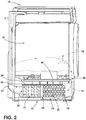
FIG. 2 is a cross-sectional view of the appliance ofFIG. 1 taken along line II-II; -
FIG. 3 is a top perspective view of a basement for a heat pump appliance incorporating an aspect of the insulating material; -
FIG. 4 is a bottom plan view of a cover member for an air conditioning chamber of a heat pump appliance that covers at least one heat exchanger; -
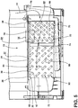
FIG. 5 is a cross-sectional view of the appliance basement ofFIG. 3 taken along line V-V; and -
FIG. 6 is an enlarged cross-sectional view of the appliance basement ofFIG. 5 taken at area VI. - For purposes of description herein the terms "upper," "lower," "right," "left," "rear," "front," "vertical," "horizontal," and derivatives thereof shall relate to the device as oriented in
FIG. 1 . However, it is to be understood that the device may assume various alternative orientations and step sequences, except where expressly specified to the contrary. It is also to be understood that the specific devices and processes illustrated in the attached drawings, and described in the following specification are simply exemplary embodiments of the inventive concepts defined in the appended claims. Hence, specific dimensions and other physical characteristics relating to the embodiments disclosed herein are not to be considered as limiting, unless the claims expressly state otherwise. - As exemplified in
FIGS. 1-6 ,reference numeral 10 generally refers to a heat pump system that is incorporated within alaundry appliance 12. Theheat pump system 10 is configured to treatprocess air 14 that is moved through theappliance 12 for processing laundry disposed within a rotatingdrum 16 of theappliance 12.Process air 14 is moved from the rotatingdrum 16 and typically carrieslint particles 18 and moisture from the rotatingdrum 16 toward thevarious heat exchangers 20 of theheat pump system 10. Theheat exchangers 20 treat theprocess air 14 to dehumidify and potentially heat theprocess air 14 to be returned to the rotatingdrum 16 to continue a particular drying operation. - Referring again to
FIGS. 1-6 , thelaundry appliance 12 can include a rotatingdrum 16 for processing laundry. Theheat pump system 10 includes theheat exchanger 20 that is positioned within anair conditioning chamber 22. Ablower 24 is configured todirect process air 14 through anair path 26 that includes the rotatingdrum 16 and theair conditioning chamber 22. An insulatingmember 28 is positioned between atop portion 30 of theheat exchanger 20 and anunderside 32 of acover member 34 for theair conditioning chamber 22. The insulatingmember 28 is configured to direct theprocess air 14 through theheat exchanger 20 and away from theunderside 32 of thecover member 34. In this manner, theinsulating member 28 occupies substantially all of aspace 36 that is defined between thetop portion 30 of theheat exchanger 20 and theunderside 32 of thecover member 34. Through use of the insulatingmember 28, theprocess air 14 can be directed or redirected toward theheat exchanger 20, thereby preventing theprocess air 14 from circumventing theheat exchanger 20 as it moves through theair conditioning chamber 22. The insulatingmember 28 also absorbs sound andvibration 38 generated by movement ofprocess air 14 through theheat exchanger 20, as will be described more fully below. - Referring again to
FIGS. 2-6 , theinsulating member 28 can be in the form of anacoustical damper 50 that absorbs sound andother vibration 38 generated by movement of theprocess air 14 through theheat exchanger 20. As theblower 24 operates, theprocess air 14 from the rotatingdrum 16 is moved through theair path 26 and into theair conditioning chamber 22 to be treated by the one ormore heat exchangers 20 disposed therein. As theprocess air 14 moves through theheat exchangers 20, the force of the processed air may cause a certain amount ofvibration 38 within thestructures 52 of theheat exchanger 20. Thesevibrations 38 may result in sound. Thesevibrations 38 and sound emanating from theheat exchanger 20 can be substantially absorbed by theacoustical damper 50 that is positioned above thetop portion 30 of theheat exchanger 20 and below theunderside 32 of thecover member 34. As theprocess air 14 moves through theheat exchangers 20, small channels that may also be defined between fins of theheat exchanger 20 or theother structures 52 of theheat exchanger 20 may also result in whistling or other resonating frequencies when theprocess air 14 moves therethrough. These resonating frequencies and whistling can also be absorbed by theacoustical damper 50 that is placed within theair conditioning chamber 22. - According to various aspects of the device, the insulating
member 28 can be secured within thespace 36 defined between theheat exchanger 20 and thecover member 34 through an adhesive. In such an embodiment, theinsulating member 28 can be adhered to theunderside 32 of thecover member 34. Typically, thecover member 34 is a removable portion of theair conditioning chamber 22 that can be removed and replaced to allow for maintenance of theheat exchangers 20 andother structures 52 within and around theair conditioning chamber 22. As thecover member 34 is removed and replaced, theinsulating member 28 that is adhered thereto remains coupled to theunderside 32 of thecover member 34. When thecover member 34 is placed on theair conditioning chamber 22 and over theheat exchangers 20, theinsulating member 28 can rest upon the top surface 54 of theheat exchanger 20. - In various embodiments of the device, the
insulating member 28 can also be compressed between thetop portion 30 of theheat exchanger 20 and theunderside 32 of thecover member 34. In such an embodiment, theinsulating member 28 has a shape that is larger than thespace 36 between thetop portion 30 of theheat exchanger 20 and theunderside 32 of thecover member 34. When thecover member 34 is placed over theheat exchangers 20, thecover member 34 presses down on the insulatingmember 28 and biases the insulatingmember 28 against thetop portion 30 of theheat exchanger 20. The insulatingmember 28 thereby forms aroundvarious structures 52 within thetop portion 30 of theheat exchanger 20, such as tubes, fins, plates, and othersimilar structures 52. This compressive engagement defines a secure engagement between theheat exchanger 20, theinsulating member 28 and thecover member 34. - To allow for the compression of the insulating
member 28, theinsulating member 28 may be any one of various compressible insulating materials. Such materials typically include various types of semi-closed-cell foam. Additionally, other types of insulating material can be used, where such insulating materials can include, but are not limited to, closed-cell foam, open-cell foam, fibrous insulation, batting-type insulation, insulating panels, spray-type insulation, combinations thereof, and other similar insulating materials. - Where the insulating material is compressed between the
cover member 34 of theair conditioning chamber 22 and thetop portion 30 of theheat exchanger 20, theinsulating member 28, in the form of theacoustical damper 50, may also engage aside surface 60 of theheat exchanger 20. In such an embodiment, as the insulatingmember 28 is compressed onto theheat exchanger 20, portions of the insulatingmember 28 may be pressed or otherwise biased downward and around thetop portion 30 of theheat exchanger 20 to engageside surfaces 60 of theheat exchanger 20. - In various aspects of the device, the insulating material can be a formable or partially elastic material that can be formed, contoured, cut, or otherwise manipulated to take the shape of the
top portion 30 of theheat exchanger 20. In such an embodiment, theinsulating member 28 conforms to the shape of theunderside 32 of thecover member 34 and also substantially conforms to the shape of thetop portion 30 of theheat exchanger 20. In the various embodiments of the device, one of the purposes of the insulatingmember 28 is to occupy thespace 36 orgap 62 defined between theheat exchanger 20 and thecover member 34. In this manner, the insulatingmember 28 can absorbvarious vibrations 38 and noises emanating from theheat exchanger 20 as a result of theprocess air 14 passing therethrough. - Another function of the insulating
member 28 is to occupy thespace 36 that is defined between theheat exchanger 20 and thecover member 34 so that theprocess air 14 can be funneled through theheat exchanger 20. By moving substantially all of theprocess air 14 through theheat exchanger 20, the thermal exchange properties of theheat exchanger 20 can be maximized to act on substantially all of theprocess air 14 within theair conditioning chamber 22. With a minimal amount of air circumventing theheat exchanger 20, the heat exchange function of theheat pump system 10 can be made more efficient during various drying operations of theappliance 12. - In various aspects of the device, the
heat exchanger 20 that is disposed within theair conditioning chamber 22 can include anevaporator 70 and acondenser 72. In such an embodiment, the insulatingmember 28 is configured to extend over each of theevaporator 70 andcondenser 72 so that the insulatingmember 28 rests on or is compressed againsttop portions 30 of each of theevaporator 70 andcondenser 72. - In various aspects, the
evaporator 70 andcondenser 72 may be disposed within separate and dedicatedair conditioning chambers 22 that are each part of theair path 26 of theappliance 12. Additionally,multiple condensers 72 may be included within theappliance 12 where onecondenser 72 may be a primarycondensing heat exchanger 20 and asecondary condenser 72 may be in the form of a refrigerant sub-cooler. In such an embodiment, various insulatingmembers 28 can be disposed on top of theheat exchangers 20 and below therespective cover members 34 to absorb sound andvibration 38 that may be generated by the movement ofprocess air 14 through thevarious heat exchangers 20. - Referring again to
FIGS. 2-6 , during operation of theappliance 12 and in particular operation of theheat pump system 10, various thermal exchange functions are performed by theevaporator 70 and thecondenser 72 of theheat pump system 10. In the case of theevaporator 70, theevaporator 70 dehumidifies theprocess air 14 delivered from therotating drum 16. Through this dehumidification of theprocess air 14, condensate is removed from theprocess air 14. This condensate can collect on the outer surface of theevaporator 70. To prevent this condensate from absorbing into the insulatingmember 28, the insulatingmember 28 is typically made of a hydrophobic material that resists absorption of this condensate into the material of the insulatingmember 28. Accordingly, the condensate generated by theevaporator 70 can be moved to a drain channel or othercondensate collection area 74 in another portion of theappliance 12. Additionally, any condensate that may collect on a surface of the insulatingmember 28 can also drip off into thiscondensate collection area 74 rather than be absorbed into the insulatingmember 28. - The insulating
member 28 can also act as a thermal barrier having various thermal insulating properties. These thermal insulating properties prevent thermal transmission ofheat 80 between the insulatingmember 28 and theevaporator 70 andcondenser 72 of theheat pump system 10. Accordingly, as theevaporator 70 of theheat pump system 10 operates,heat 80 is absorbed from areas around theheat exchanger 20. By absorbingheat 80 around theevaporator 70, the temperature of areas around theevaporator 70 are decreased, resulting in dehumidification of theprocess air 14 moving through theevaporator 70. Because the insulatingmember 28 is a thermal barrier having thermally insulating properties, minimal amounts ofheat 80 are absorbed from the insulatingmember 28 or through the insulatingmember 28. Accordingly, the absorption ofheat 80 is configured to take place within the immediate area surrounding theevaporator 70. - This thermally insulating property of the insulating
member 28 serves to make theevaporator 70 more efficient by absorbingheat 80 fromprocess air 14 as opposed to areas within or above the insulatingmember 28. - With respect to the
condenser 72, these thermally insulating properties of the insulatingmember 28 serve to resistheat 80 rejected from thecondenser 72 from entering into and/or passing through the insulatingmember 28. As with theevaporator 70, the insulatingmember 28 allows for thecondenser 72 toheat process air 14 in the area immediately surrounding and within thecondenser 72, rather than heating areas within and above the insulatingmember 28. - Referring again to
FIGS. 1-6 , a heat exchange system for theappliance 12 having aheat pump system 10 can include theblower 24 that directsprocess air 14 through theair path 26 that includes therotating drum 16. Theheat pump system 10 includes theevaporator 70 positioned within theair path 26 for dehumidifying theprocess air 14. Atop portion 30 of theevaporator 70 is separated from an inside surface of theair path 26 by agap 62. The insulatingmember 28 is positioned to occupy thegap 62 and engage thetop portion 30 of theheat exchanger 20 as well as the inside surface of theair path 26. In this manner, the insulatingmember 28 directs theprocess air 14 away from thegap 62 and into theevaporator 70. Additionally, the insulatingmember 28 absorbs sound generated by movement of theprocess air 14 through theevaporator 70. - As discussed above, the
evaporator 70 can be positioned within theair conditioning chamber 22 of theair path 26. In such an embodiment, thegap 62 is located between thetop portion 30 of theevaporator 70 and thecover member 34 of theair conditioning chamber 22. - Referring again to
FIGS. 2-6 , thecondenser 72 of theheat pump system 10 that serves to heat theprocess air 14 within theair path 26 is typically disposed at a position downstream of theevaporator 70. Typically, a portion of the insulatingmember 28 extends over thecondenser 72 to directprocess air 14 into thecondenser 72 and also to absorb sound andvibration 38 generated by movement of theprocess air 14 through thecondenser 72. As discussed previously, thecondenser 72 is typically located within theair conditioning chamber 22 and is connected to theevaporator 70. In such an embodiment, the insulatingmember 28 extends continuously over theevaporator 70 and thecondenser 72 to occupy thegap 62 that is defined between thetop portion 30 of theevaporator 70 and theunderside 32 of thecover member 34 and also between thetop portion 30 of thecondenser 72 and anunderside 32 of thecover member 34. - The insulating
member 28 can be retained within thegap 62 through various configurations and mechanisms. In at least one aspect of the device, the insulatingmember 28 can be adhered to theunderside 32 of thecover member 34 and the insulatingmember 28 occupies thegap 62 defined between the heat exchangers 20 (theevaporator 70 and the condenser 72) and thecover member 34. The insulatingmember 28 can also be compressed between theunderside 32 of thecover member 34 and the top surface 54 of theevaporator 70 and the top surface 54 of thecondenser 72. As described above, the insulatingmember 28 can typically be in the form of anacoustical damper 50 that absorbs sound generated by movement of theprocess air 14 through theevaporator 70 and thecondenser 72. By having the insulatingmember 28 occupy theentire gap 62 between thecover member 34 and theevaporator 70 andcondenser 72, the insulatingmember 28 can absorbvibration 38, resonance, sound, and other frequencies generated through operation of theheat pump system 10 and also through the passage ofprocess air 14 through theevaporator 70 andcondenser 72. - Referring again to
FIGS. 1-6 , the heat exchange system for theheat pump appliance 12 can include ablower 24 that directsprocess air 14 through theair path 26 and includes therotating drum 16 and aheat exchange cavity 90. According to various aspects of the device, theheat exchange cavity 90 can be defined within theair conditioning chamber 22 having thecover member 34. Theheat pump system 10 for theappliance 12 includes theevaporator 70 and acondenser 72 that are positioned within theheat exchange cavity 90 for dehumidifying and heating theprocess air 14, respectively. Anacoustical damper 50 can be compressed between the top surfaces 54 of theevaporator 70 and thecondenser 72, and an interior surface of theheat exchange cavity 90. In such an embodiment, the acoustical member directs theprocess air 14 away from thegap 62 and into theevaporator 70 andcondenser 72, and also absorbs sound generated by the movement ofprocess air 14 through theevaporator 70 andcondenser 72. According to various aspects of the device, the acoustical member can be in the form of a semi-closed-cell foam that is disposed within thegap 62. - According to various aspects of the device, the insulating
member 28 can be disposed within the variousheat pump systems 10 for a wide range ofappliances 12.Such appliances 12 can include, but are not limited to, dryers, combination washers and dryers, refrigerators, coolers, freezers, air conditioners, humidity-controlling appliances, and other similar appliances. - The use of the insulating
member 28 can include single pieces that are disposed over eachheat exchanger 20 of theheat pump system 10 separately. Additionally, the insulatingmember 28 can be a continuous piece that is disposed overmultiple heat exchangers 20 within theheat pump system 10. Typically, wheremultiple heat exchangers 20 are included within a singleheat exchange cavity 90, theheat exchange cavity 90 will include a single insulatingmember 28. Wheremultiple heat exchangers 20 are disposed in separate and dedicated cavities, each of these dedicated cavities will typically have a separate insulatingmember 28 disposed between the top surface 54 of therespective heat exchanger 20 and thecover member 34 for the particularheat exchange cavity 90.
Claims (15)
- A laundry appliance (12) comprising:a rotating drum (16) for processing laundry;a heat pump system (10) having a heat exchanger (20) that is positioned within an air conditioning chamber (22);a blower (24) that directs process air (14) through an air path (26) that includes the rotating drum (16) and the air conditioning chamber (22);an insulating member (28) positioned between a top portion (30) of the heat exchanger (20) and an underside (32) of a cover member (34) for the air conditioning chamber (22), wherein the insulating member (28) directs the process air (14) through the heat exchanger (20) and away from the underside (32) of the cover member (34).
- The laundry appliance (12) of claim 1, wherein the insulating member (28) absorbs sound and vibration (38) generated by movement of process air (14) through the heat exchanger(20).
- The laundry appliance (12) of any one or more of claims 1-2, wherein the insulating member (28) occupies substantially all of a space (36) defined between the top portion (30) of the heat exchanger (20) and the underside (32) of the cover member (34).
- The laundry appliance (12) of any one or more of claims 1-3, wherein the insulating member (28) is a semi-closed-cell foam.
- The laundry appliance (12) of any one or more of claims 1-4, wherein the insulating member (28) is adhered to the underside (32) of the cover member (34) and rests upon a top surface (54) of the heat exchanger (20).
- The laundry appliance (12) of any one or more of claims 1-5, wherein the heat exchanger (20) includes an evaporator (70) and a condenser (72), wherein the insulating member (28) extends over at least the evaporator (70).
- The laundry appliance (12) of any one or more of claims 1-6, wherein the insulating member (28) extends over each of the evaporator (70) and the condenser (72).
- The laundry appliance (12) of any one or more of claims 1-7, wherein the insulating member (28) is an acoustical damper (50) that absorbs sound generated by movement of the process air (14) through the heat exchanger (20).
- The laundry appliance (12) of any one or more of claims 1-8, wherein the insulating member (28) engages a side surface (60) of the heat exchanger (20).
- The laundry appliance (12) of any one or more of claims 1-9, wherein the insulating member (28) is made of a hydrophobic material.
- The laundry appliance (12) of any one or more of claims 1-10, wherein the cover member (34) is a separate piece that is coupled with the air conditioning chamber (22).
- The laundry appliance (12) of any one or more of claims 1-11, wherein the insulating member (28) is compressed between the top portion (30) of the heat exchanger (20) and the underside (32) of the cover member (34).
- The laundry appliance (12) of any one or more of claims 1-12, wherein the insulating member (28) is a thermal barrier that limits thermal transmission between the heat exchanger (20) and the underside (32) of the cover member (34).
- The laundry appliance (12) of any one or more of claims 7-13, wherein the insulating member (28) defines a single member that extends continuously over each of the evaporator (70) and the condenser (72).
- The laundry appliance (12) of claim 14, wherein a portion of the insulating member (28) is positioned between the evaporator (70) and the condenser (72).
Applications Claiming Priority (1)
| Application Number | Priority Date | Filing Date | Title |
|---|---|---|---|
| US15/674,753 US10718082B2 (en) | 2017-08-11 | 2017-08-11 | Acoustic heat exchanger treatment for a laundry appliance having a heat pump system |
Publications (1)
| Publication Number | Publication Date |
|---|---|
| EP3441518A1 true EP3441518A1 (en) | 2019-02-13 |
Family
ID=63041924
Family Applications (1)
| Application Number | Title | Priority Date | Filing Date |
|---|---|---|---|
| EP18185317.7A Withdrawn EP3441518A1 (en) | 2017-08-11 | 2018-07-24 | Acoustic heat exchanger treatment for a laundry appliance having a heat pump system |
Country Status (2)
| Country | Link |
|---|---|
| US (1) | US10718082B2 (en) |
| EP (1) | EP3441518A1 (en) |
Families Citing this family (2)
| Publication number | Priority date | Publication date | Assignee | Title |
|---|---|---|---|---|
| CN113529378B (en) * | 2020-04-21 | 2023-07-14 | 无锡飞翎电子有限公司 | Base assembly for clothes dryer and clothes dryer having same |
| CN115726126B (en) * | 2021-08-30 | 2025-12-02 | 无锡小天鹅电器有限公司 | Clothing processing device |
Citations (2)
| Publication number | Priority date | Publication date | Assignee | Title |
|---|---|---|---|---|
| DE102007010272A1 (en) * | 2007-03-02 | 2008-09-04 | BSH Bosch und Siemens Hausgeräte GmbH | Condensation dryer for drying laundry has outer surface of first wall of process air channel outside heat exchanger |
| WO2015189129A1 (en) * | 2014-06-13 | 2015-12-17 | BSH Hausgeräte GmbH | Base assembly for a clothes dryer, and clothes dryer having a base assembly of this type |
Family Cites Families (257)
| Publication number | Priority date | Publication date | Assignee | Title |
|---|---|---|---|---|
| US2515825A (en) | 1945-03-16 | 1950-07-18 | Carrier Corp | Single stage refrigeration utilizing holdover means |
| US2873041A (en) | 1956-12-03 | 1959-02-10 | Carrier Corp | Breaker strip construction |
| US2934023A (en) | 1956-12-31 | 1960-04-26 | Murray Corp | Centrifugal pumps |
| US3196553A (en) | 1960-09-19 | 1965-07-27 | Gen Motors Corp | Temperature responsive timer control for a clothes drier |
| US3342961A (en) | 1960-09-19 | 1967-09-19 | Gen Motors Corp | Thermostat having thermally responsive means for arresting the movement of one of the contacts upon cooling of the thermostat |
| US3218730A (en) | 1962-06-14 | 1965-11-23 | Gen Motors Corp | Termination control for a condensing clothes dryer |
| US3653807A (en) | 1970-08-24 | 1972-04-04 | Whirlpool Co | Method and means for shredding and filtering lint in a washing machine |
| US3805404A (en) | 1973-07-02 | 1974-04-23 | I Gould | Water cooled condenser dryer for laundry center |
| US3953146A (en) | 1974-08-15 | 1976-04-27 | Whirlpool Corporation | Apparatus for treating lint in an automatic washer |
| US3999304A (en) | 1975-07-18 | 1976-12-28 | Doty Edward E | Clothes dryer filter and exhaust system |
| US4137647A (en) | 1977-09-06 | 1979-02-06 | Clark Jr James N | Heat and humidity recovery device for use with clothes dryer |
| US4134518A (en) | 1978-01-23 | 1979-01-16 | Bernie Menchen | Cold box with breaker strip |
| NL7801958A (en) | 1978-02-21 | 1979-08-23 | Zephyr Koel En Luchttechniek B | Refrigerated transport container system - has secondary circuit with pump and containing liq. refrigerating agent |
| US4261179A (en) | 1978-09-22 | 1981-04-14 | Ardco, Inc. | Input control system |
| US4260876A (en) | 1978-12-11 | 1981-04-07 | Anthony's Manufacturing Company, Inc. | Dew point differential power controller |
| GB2087029A (en) | 1980-09-19 | 1982-05-19 | Heat Pumps W R Ltd | Improvements in or Relating to Heat Exchangers |
| DE3147796A1 (en) | 1981-08-18 | 1983-03-03 | Spraytech AB, 18400 Åkersberga | Device for cleaning the warm exhaust air of a linen drier |
| US4860921A (en) | 1984-05-09 | 1989-08-29 | Edward Gidseg | Thermal breaker strip for refrigeration cabinets |
| US4603489A (en) | 1984-10-05 | 1986-08-05 | Michael Goldberg | Heat pump closed loop drying |
| US4870735A (en) | 1987-07-31 | 1989-10-03 | White Consolidated Industries, Inc. | Refrigeration cabinet construction |
| DE3738031C2 (en) | 1987-11-09 | 1995-10-12 | Bosch Siemens Hausgeraete | Method and device for removing lint from a condensate separator designed as a heat exchanger |
| IT1243685B (en) | 1990-07-24 | 1994-06-21 | Eurodomestici Ind Riunite | DEVICE FOR THE CLEANING OF AN EVAPORATOR, PROVIDED FOR IN A MACHINE-DRYER OR SIMILAR, FROM ELEMENTS RELEASED BY CLOTHING OR SIMILAR PRESENT IN THE BASKET OF SUCH MACHINE |
| KR950001350B1 (en) | 1992-02-25 | 1995-02-17 | 동양매직 주식회사 | Washing machine |
| DE4304372A1 (en) | 1993-02-13 | 1994-08-18 | Miele & Cie | Drying appliance, especially condensation-type laundry dryer, with a heat pump |
| DE4409607C2 (en) | 1993-04-21 | 2002-03-14 | Miele & Cie | Condensation clothes dryer with a heat pump |
| US5628122A (en) | 1994-10-05 | 1997-05-13 | Peter And Theordore Spinardi Investments | Lint remover for a clothes drying machine |
| US5720536A (en) | 1995-03-27 | 1998-02-24 | General Electric Company | Refrigerator with improved breaker strip assembly |
| US5600966A (en) | 1995-05-19 | 1997-02-11 | Forma Scientific, Inc. | Ultra low temperature split door freezer |
| IT1284443B1 (en) | 1996-06-26 | 1998-05-21 | Candy Spa | DOMESTIC WASHING MACHINE WITH CLOSED DRYING CIRCUIT, AIR CONDENSATION OF THE STEAM AND SELF-CLEANING FILTER |
| US5666817A (en) | 1996-12-10 | 1997-09-16 | Edward R. Schulak | Energy transfer system for refrigerator/freezer components |
| US5927095A (en) | 1997-05-20 | 1999-07-27 | Lg Electronics, Inc. | Anti-frost device for refrigerators |
| JP4018238B2 (en) | 1997-05-27 | 2007-12-05 | エルジー エレクトロニクス インコーポレイティド | Cold air supply system for refrigerator |
| DE69832212T2 (en) | 1997-05-28 | 2006-07-20 | Lg Electronics Inc. | fridge |
| KR100223225B1 (en) | 1997-08-28 | 1999-10-15 | 구자홍 | Refrigerator room temperature control method and apparatus |
| KR100254409B1 (en) | 1997-08-29 | 2000-05-01 | 구자홍 | Circulator for cooling air |
| KR100288261B1 (en) | 1998-06-30 | 2001-05-02 | 전주범 | Dew device of refrigerator |
| EP0999302B1 (en) | 1998-10-21 | 2003-08-20 | Whirlpool Corporation | Tumble dryer with a heat pump |
| ATE247735T1 (en) | 1999-04-30 | 2003-09-15 | Bsh Bosch Siemens Hausgeraete | METHOD FOR CLEANING THE PROCESS AIR LINE OF A DOMESTIC LAUNDRY DRYER AND A HOUSEHOLD LAUNDRY DRYER SET UP TO PERFORM THIS METHOD |
| DE10002743B4 (en) | 2000-01-22 | 2006-01-12 | Whirlpool Corp., Benton Harbor | Heat pump tumble dryer with cleaning device for the heat exchanger |
| DE10002742C1 (en) | 2000-01-22 | 2001-06-28 | Whirlpool Co | Heat pump washer-dryer has channel wall forming or carrying removable condensate collection unit, adjustable cleaning device near heat exchanger inlet removing adhering fluff |
| DE20001253U1 (en) | 2000-01-25 | 2001-06-07 | Liebherr-Hausgeräte GmbH, 88416 Ochsenhausen | Refrigerator with a refrigerator, a cold storage and a freezer compartment |
| CA2355155C (en) | 2000-08-16 | 2009-10-13 | Lg Electronics Inc. | Door cooling apparatus for refrigerator with double-acting door |
| JP4028688B2 (en) | 2001-03-21 | 2007-12-26 | 株式会社東芝 | refrigerator |
| DE10116238B4 (en) | 2001-03-31 | 2005-03-10 | Whirlpool Co | Clothes dryer with heat pump |
| US6983615B2 (en) | 2001-07-16 | 2006-01-10 | Maytag Corporation | French door chiller compartment for refrigerators |
| DE10140005A1 (en) | 2001-08-16 | 2003-02-27 | Bsh Bosch Siemens Hausgeraete | Combination refrigerator and evaporator arrangement therefor |
| DE10143242A1 (en) | 2001-09-04 | 2003-03-20 | Bsh Bosch Siemens Hausgeraete | Refrigeration device with cooling air circulation |
| NZ534444A (en) | 2002-02-22 | 2006-02-24 | Multibras S | |
| JP2004053055A (en) | 2002-07-17 | 2004-02-19 | Sanyo Electric Co Ltd | Refrigerator |
| US6973799B2 (en) | 2002-08-27 | 2005-12-13 | Whirlpool Corporation | Distributed refrigeration system for a vehicle |
| KR100487329B1 (en) | 2002-10-10 | 2005-05-03 | 엘지전자 주식회사 | Condensing Type Clothes Drier and Controlling the Same |
| JP3696224B2 (en) | 2003-03-19 | 2005-09-14 | 株式会社グリーンセイジュ | Drying system |
| BR0301406A (en) | 2003-04-15 | 2004-12-07 | Multibras Eletrodomesticos Sa | Arrangement for forced air circulation in refrigerators and freezers |
| US7168274B2 (en) | 2003-05-05 | 2007-01-30 | American Dryer Corporation | Combination washer/dryer having common heat source |
| NZ526361A (en) | 2003-05-30 | 2006-02-24 | Fisher & Paykel Appliances Ltd | Compressor improvements |
| US6793010B1 (en) | 2003-06-06 | 2004-09-21 | Tecumseh Products Company | Heat exchanger having non-perpendicularly aligned heat transfer elements |
| KR101041070B1 (en) * | 2003-06-13 | 2011-06-13 | 삼성전자주식회사 | Drum washing machine |
| JP2005027768A (en) | 2003-07-09 | 2005-02-03 | Mitsubishi Electric Corp | Clothes dryer |
| CA2438766C (en) | 2003-08-29 | 2008-12-30 | Maytag Corporation | Refrigerator incorporating french doors with rotating mullion bar |
| KR100565622B1 (en) | 2003-09-19 | 2006-03-30 | 엘지전자 주식회사 | Refrigerator |
| US20070051127A1 (en) | 2003-09-26 | 2007-03-08 | Ssw Holding Company, Inc. | Cooling tubes for shelving |
| RU2006114770A (en) | 2003-09-29 | 2007-11-10 | Селф Пропеллед Рисерч энд Дивелопмент Спешелистс,эЛэЛСи (US) | DRYING DEVICE (OPTIONS), WASHING DEVICE AND DRYING CHAMBER (OPTIONS) |
| EP1548380A3 (en) | 2003-12-22 | 2006-10-04 | Hussmann Corporation | Flat-tube evaporator with micro-distributor |
| EP1564325B1 (en) | 2004-02-10 | 2018-04-11 | Electrolux Home Products Corporation N.V. | Improved clothes drying machine with clothes smoothing ability |
| US20050229614A1 (en) | 2004-04-02 | 2005-10-20 | Altech Controls, Inc. | Anti-sweat heater control system and method |
| KR100531834B1 (en) | 2004-04-06 | 2005-11-30 | 엘지전자 주식회사 | Exhaustion type clothes dryer with air inlet guide |
| US7281387B2 (en) | 2004-04-29 | 2007-10-16 | Carrier Commercial Refrigeration Inc. | Foul-resistant condenser using microchannel tubing |
| JP2006017338A (en) | 2004-06-30 | 2006-01-19 | Toshiba Corp | refrigerator |
| US7421846B2 (en) | 2004-08-18 | 2008-09-09 | Ice Energy, Inc. | Thermal energy storage and cooling system with gravity fed secondary refrigerant isolation |
| KR100738714B1 (en) | 2004-12-10 | 2007-07-12 | 엘지전자 주식회사 | Drying Washer |
| JP2006187449A (en) | 2005-01-06 | 2006-07-20 | Toshiba Corp | Washing and drying machine |
| US7775065B2 (en) | 2005-01-14 | 2010-08-17 | General Electric Company | Methods and apparatus for operating a refrigerator |
| US20080307823A1 (en) | 2005-02-01 | 2008-12-18 | Lg Electronics Inc. | Refrigerator |
| US7207181B2 (en) | 2005-03-01 | 2007-04-24 | Bradley W. Geuke | Refrigeration unit condensation prevention |
| JP4834342B2 (en) | 2005-07-26 | 2011-12-14 | 株式会社東芝 | Drum type washer / dryer |
| KR100925908B1 (en) | 2005-07-28 | 2009-11-09 | 샤프 가부시키가이샤 | Drum type drying and washing machine |
| DE102005035652A1 (en) | 2005-07-29 | 2007-02-01 | BSH Bosch und Siemens Hausgeräte GmbH | Heat exchanger device for a tumble dryer |
| KR100661663B1 (en) | 2005-08-12 | 2006-12-26 | 삼성전자주식회사 | Refrigerator and its control method |
| KR101137335B1 (en) | 2005-08-25 | 2012-04-19 | 엘지전자 주식회사 | operating method for laundry machine |
| DE102005041145A1 (en) | 2005-08-29 | 2007-03-01 | Alpha-Innotec Gmbh | Laundry dryer, has heat pump heating system comprising compressor with changeable output, and controller controlling and/or regulating output of compressor based on residual moisture in laundry that is to be dried |
| US9663894B2 (en) | 2005-11-10 | 2017-05-30 | Lg Electronics Inc. | Steam generator and laundry dryer having the same and controlling method thereof |
| JP4661590B2 (en) | 2005-12-27 | 2011-03-30 | パナソニック株式会社 | Motor drive device for washing and drying machine |
| DE102005062940A1 (en) | 2005-12-29 | 2007-07-05 | BSH Bosch und Siemens Hausgeräte GmbH | A method for drying washing has a heat pump by which circulated air through the washing chamber is dried and heated and an additional heat pump evaporator is arranged to predry the circulated air stream |
| DE102006007443A1 (en) | 2006-02-17 | 2007-08-23 | BSH Bosch und Siemens Hausgeräte GmbH | Cleaning device for a component of a household laundry drier |
| DE102006007420A1 (en) | 2006-02-17 | 2007-08-30 | BSH Bosch und Siemens Hausgeräte GmbH | Cleaning device for a component within a process air cycle of a household laundry drier |
| DE102006018469A1 (en) | 2006-04-19 | 2007-10-25 | Lare Luft- und Kältetechnik Apparate und Regelsysteme GmbH | Cloth drier comprises a replaceable or cleanable water filter, electric control with a program for controlling a pump and a component for opening and closing a flow pipeline, heat pump system, aerator, condenser, compressor and evaporator |
| EP1852539B1 (en) | 2006-05-02 | 2010-07-14 | Electrolux Home Products Corporation N.V. | Drying program with anti-crease phase and dryer |
| KR100783211B1 (en) | 2006-07-19 | 2007-12-06 | 엘지전자 주식회사 | Valve assembly for preventing leakage of refrigerant in refrigerator |
| US7610773B2 (en) | 2006-12-14 | 2009-11-03 | General Electric Company | Ice producing apparatus and method |
| DE102006061211A1 (en) | 2006-12-22 | 2008-06-26 | BSH Bosch und Siemens Hausgeräte GmbH | Method for removing lint from a heat exchanger of a domestic appliance, and corresponding domestic appliance |
| DE102006061737B3 (en) | 2006-12-28 | 2008-04-24 | BSH Bosch und Siemens Hausgeräte GmbH | Condensing dryer has fan driven circuit for processing air and a heat pump circuit with a secondary fluid circuit between them |
| DE102007002181B3 (en) | 2007-01-15 | 2008-08-21 | BSH Bosch und Siemens Hausgeräte GmbH | Condensation dryer with a heat pump |
| KR100820151B1 (en) | 2007-02-20 | 2008-04-08 | 엘지전자 주식회사 | Ductless dryer |
| DE102007012071A1 (en) | 2007-03-13 | 2008-09-18 | BSH Bosch und Siemens Hausgeräte GmbH | Washer dryer with improved lint removal and process for its operation |
| DE102007016074A1 (en) | 2007-04-03 | 2008-10-09 | BSH Bosch und Siemens Hausgeräte GmbH | Method and device for cleaning a component, in particular an evaporator of a condenser device, and laundry or tumble dryer with such a device |
| CN101324389B (en) | 2007-06-13 | 2011-11-09 | 博西华家用电器有限公司 | Condenser combination and household electrical appliance using the same |
| EP2203585B1 (en) | 2007-09-04 | 2017-08-16 | LG Electronics Inc. | Dehumidifying apparatus for dryer |
| DE102007052835A1 (en) | 2007-11-06 | 2009-05-07 | BSH Bosch und Siemens Hausgeräte GmbH | Method and device for cleaning a component, in particular an evaporator of a condenser device, and laundry or tumble dryer with such a device |
| JP2011506903A (en) | 2007-12-18 | 2011-03-03 | アー − ヒート アライド ヒート イクスチェンジ テクノロジー アクチェンゲゼルシャフト | Heat exchanger |
| EP2225528B1 (en) | 2007-12-18 | 2011-09-07 | A-Heat AlliedHeat Exchange Technology AG | Heat exchange system |
| DE102007060854A1 (en) | 2007-12-18 | 2009-06-25 | BSH Bosch und Siemens Hausgeräte GmbH | Cleaning device for a component loaded with lint in a domestic appliance, and domestic appliance and method for cleaning a component loaded with lint |
| DE102007060851A1 (en) | 2007-12-18 | 2009-06-25 | BSH Bosch und Siemens Hausgeräte GmbH | Household appliance for the care of laundry items and method for removing lint |
| US8806886B2 (en) | 2007-12-20 | 2014-08-19 | General Electric Company | Temperature controlled devices |
| US8099975B2 (en) | 2007-12-31 | 2012-01-24 | General Electric Company | Icemaker for a refrigerator |
| WO2009089460A2 (en) | 2008-01-09 | 2009-07-16 | International Mezzo Technologies, Inc. | Corrugated micro tube heat exchanger |
| DE102008007971A1 (en) | 2008-02-07 | 2009-08-13 | BSH Bosch und Siemens Hausgeräte GmbH | Condensation dryer with heat pump and heater and method for its operation |
| US8794026B2 (en) | 2008-04-18 | 2014-08-05 | Whirlpool Corporation | Secondary cooling apparatus and method for a refrigerator |
| CA2629470A1 (en) | 2008-04-18 | 2009-10-18 | Mabe Canada Inc. | Clothes dryer with thermal insulation pad |
| DE102008020351A1 (en) | 2008-04-23 | 2009-10-29 | Valeo Klimasysteme Gmbh | Method for operating an air conditioning system for a motor vehicle |
| DE102008020556A1 (en) | 2008-04-24 | 2009-10-29 | BSH Bosch und Siemens Hausgeräte GmbH | Exhaust air dryer with reduced condensate formation and method for its operation |
| PL2138627T3 (en) | 2008-06-27 | 2017-01-31 | BSH Hausgeräte GmbH | Dryer comprising a heat sink and a condensate container |
| DE102008032800A1 (en) | 2008-07-11 | 2010-01-14 | BSH Bosch und Siemens Hausgeräte GmbH | Device for cleaning a component, in particular an evaporator of a capacitor device |
| DE102008033388B4 (en) | 2008-07-16 | 2020-07-16 | BSH Hausgeräte GmbH | Dryer with heat pump circuit |
| US8104191B2 (en) | 2008-07-31 | 2012-01-31 | Electrolux Home Products, Inc. | Laundry dryer providing moisture application during tumbling and reduced airflow |
| DE102008040946A1 (en) | 2008-08-01 | 2010-02-04 | BSH Bosch und Siemens Hausgeräte GmbH | Condensation dryer with a heat pump and detection of an impermissible operating state and method for its operation |
| DE102008041998A1 (en) | 2008-09-11 | 2010-03-18 | BSH Bosch und Siemens Hausgeräte GmbH | Dryer with a lint filter and a cleaning device |
| KR101549861B1 (en) | 2008-09-16 | 2015-09-03 | 엘지전자 주식회사 | ductless dryer |
| AU2009301278B2 (en) | 2008-10-08 | 2015-11-19 | A-Heat Allied Heat Exchange Technology Ag | Heat exchanger assembly and method for the operation thereof |
| DE102008043920A1 (en) | 2008-11-20 | 2010-05-27 | BSH Bosch und Siemens Hausgeräte GmbH | Condensation dryer with a heat pump and method for its operation |
| EP2189568B1 (en) | 2008-11-21 | 2012-01-04 | Electrolux Home Products Corporation N.V. | Laundry washing and drying machine |
| DE102008044323A1 (en) | 2008-12-03 | 2010-06-10 | BSH Bosch und Siemens Hausgeräte GmbH | Condensation dryer with a housing |
| DE102008054548A1 (en) | 2008-12-11 | 2010-06-17 | BSH Bosch und Siemens Hausgeräte GmbH | Dryer with recirculating air and process for its operation |
| DE102008054693A1 (en) | 2008-12-16 | 2010-06-17 | BSH Bosch und Siemens Hausgeräte GmbH | Condensation dryer and method for its operation |
| DE102008054832A1 (en) | 2008-12-17 | 2010-07-01 | BSH Bosch und Siemens Hausgeräte GmbH | Device for cleaning component, particularly condenser unit arranged in processing air circuit of wash or laundry dryer, has condensate flowing through fibrous material filter on way to condensate container |
| US9062410B2 (en) | 2008-12-17 | 2015-06-23 | Lg Electronics Inc. | Dryer and foreign material removing apparatus thereof |
| DE102008055086A1 (en) | 2008-12-22 | 2010-06-24 | BSH Bosch und Siemens Hausgeräte GmbH | Clothes drying apparatus and method for cleaning a screen |
| DE102008055093A1 (en) | 2008-12-22 | 2010-06-24 | BSH Bosch und Siemens Hausgeräte GmbH | Household appliance strainer, household appliance with such a sieve and method for producing such a sieve |
| US8074469B2 (en) | 2008-12-31 | 2011-12-13 | General Electric Company | Refrigerator with a convertible compartment |
| EP2398947B1 (en) | 2009-02-23 | 2016-10-26 | LG Electronics Inc. | Washing / drying machine |
| DE102009001548A1 (en) | 2009-03-13 | 2010-09-16 | BSH Bosch und Siemens Hausgeräte GmbH | A laundry drying apparatus having a lint filter disposed within a process air cycle and method of operating the laundry dryer |
| DE102009002076A1 (en) | 2009-04-01 | 2010-10-07 | BSH Bosch und Siemens Hausgeräte GmbH | Rinsing container, apparatus for rinsing a component of a laundry drying apparatus and laundry drying apparatus |
| DE102009002389A1 (en) | 2009-04-15 | 2010-10-21 | BSH Bosch und Siemens Hausgeräte GmbH | Condensation dryer with a filter device and method for its operation |
| US9010145B2 (en) | 2009-06-01 | 2015-04-21 | Samsung Electronics Co., Ltd. | Refrigerator |
| US9303882B2 (en) | 2009-06-26 | 2016-04-05 | Trane International Inc. | Blow through air handler |
| US8511109B2 (en) | 2009-07-15 | 2013-08-20 | Whirlpool Corporation | High efficiency refrigerator |
| CN101967746A (en) | 2009-07-27 | 2011-02-09 | 海尔集团公司 | Drum type washing and drying machine and temperature detection method |
| EP2284310B1 (en) | 2009-08-12 | 2014-07-09 | Electrolux Home Products Corporation N.V. | A tumble dryer with a heat pump system and a method for controlling a heat pump system for a tumble dryer |
| US9027371B2 (en) | 2009-08-18 | 2015-05-12 | Whirlpool Corporation | Heat pump (server) coupled washer and dryer pair |
| US8915104B2 (en) | 2009-08-18 | 2014-12-23 | Bruce C. Beihoff | Heat pump (server) coupled washer and dryer pair |
| KR20110032611A (en) | 2009-09-23 | 2011-03-30 | 엘지전자 주식회사 | Refrigerator |
| US7980093B2 (en) | 2009-09-25 | 2011-07-19 | Whirlpool Corporation | Combined refrigerant compressor and secondary liquid coolant pump |
| DE102009046683A1 (en) | 2009-11-13 | 2011-05-19 | BSH Bosch und Siemens Hausgeräte GmbH | Device for cleaning a component of a dryer, dryer with such a device and method for cleaning a component of a dryer |
| DE102009046921A1 (en) | 2009-11-20 | 2011-05-26 | BSH Bosch und Siemens Hausgeräte GmbH | Dryer with a lint filter and a cleaning device |
| FR2954782B1 (en) | 2009-12-30 | 2012-03-09 | Fagorbrandt Sas | DRYING MACHINE COMPRISING A CONDENSING WATER RESERVE SUPPLYING A DEVICE FOR CLEANING A HEAT EXCHANGER AND A STEAM GENERATOR. |
| AU2011210122B2 (en) | 2010-02-01 | 2013-06-06 | Lg Electronics Inc. | Refrigerator |
| US20110277334A1 (en) | 2010-04-28 | 2011-11-17 | Lee Yongju | Cloth treating apparatus |
| EP2565323B1 (en) | 2010-04-28 | 2018-12-19 | LG Electronics Inc. | Method for controlling the operation of a dryer |
| CN102859063A (en) | 2010-04-28 | 2013-01-02 | Lg电子株式会社 | Control method of dryer |
| AU2011249152B2 (en) | 2010-05-07 | 2013-11-07 | Lg Electronics Inc. | Clothes treating apparatus and filter technology |
| EP2386679B1 (en) | 2010-05-13 | 2020-07-01 | Samsung Electronics Co., Ltd. | Clothes dryer |
| CN102947657B (en) | 2010-06-22 | 2015-04-22 | Lg电子株式会社 | Refrigerator and method of manufacturing the same |
| US20120005912A1 (en) | 2010-07-08 | 2012-01-12 | Lee Yongju | Clothes dryer |
| DE102010031459A1 (en) | 2010-07-16 | 2012-01-19 | BSH Bosch und Siemens Hausgeräte GmbH | Diffuser for low height |
| US8434317B2 (en) | 2010-08-19 | 2013-05-07 | General Electric Company | Anti-sweat heater demand supply module using temperature and humidity control |
| DE102010039552A1 (en) | 2010-08-20 | 2012-02-23 | BSH Bosch und Siemens Hausgeräte GmbH | Laundry treatment device with sieve holder and method for operating a laundry treatment device with a lint filter |
| GB2483446A (en) * | 2010-09-07 | 2012-03-14 | Smith S Environmental Products Ltd | Sound attenuating housing, particularly for use with a heat pump |
| KR101716821B1 (en) | 2010-10-12 | 2017-03-15 | 삼성전자주식회사 | Clothes dryer and lint cleaning device thereof |
| US8572862B2 (en) | 2010-10-25 | 2013-11-05 | Battelle Memorial Institute | Open-loop heat-recovery dryer |
| EP2455526A1 (en) | 2010-11-17 | 2012-05-23 | BSH Bosch und Siemens Hausgeräte GmbH | Machine comprising a heat pump and related set of processes |
| KR101788600B1 (en) | 2010-11-17 | 2017-10-20 | 엘지전자 주식회사 | Refrigerator with a convertible chamber and an operation method thereof |
| ITTO20101018A1 (en) | 2010-12-20 | 2012-06-21 | Indesit Co Spa | MACHINE FOR DRYING OF LINEN FOR HOME USE |
| ITTO20101022A1 (en) | 2010-12-20 | 2012-06-21 | Indesit Co Spa | MACHINE FOR DRYING OF LINEN FOR HOME USE |
| CH701685B1 (en) | 2010-12-24 | 2018-12-14 | V Zug Ag | Clothes dryer with temperature-controlled additional heat exchanger. |
| PL2471994T3 (en) | 2011-01-04 | 2019-12-31 | Electrolux Home Products Corporation N.V. | Appliance for drying laundry |
| PL2478969T3 (en) | 2011-01-24 | 2017-08-31 | Electrolux Home Products Corporation N.V. | Home appliance |
| ES2617216T3 (en) | 2011-03-29 | 2017-06-15 | Lg Electronics Inc. | Clothing treatment apparatus incorporating a cleaning device with heat exchanger |
| WO2012138136A2 (en) | 2011-04-05 | 2012-10-11 | 엘지전자 주식회사 | Laundry machine and method for cleaning lint filter of laundry machine |
| US9834882B2 (en) | 2011-07-07 | 2017-12-05 | Haier Us Appliance Solutions, Inc. | Device and method for heat pump based clothes dryer |
| JP2013019623A (en) | 2011-07-13 | 2013-01-31 | Panasonic Corp | Refrigerator |
| SE537671C2 (en) | 2011-08-15 | 2015-09-29 | Asko Cylinda Ab | Cloth dryer with lint filter cleaning mechanism |
| US20130061757A1 (en) | 2011-09-14 | 2013-03-14 | Abdulreidha A.T.A. Alsaffar | System for decontaminating industrial output gases |
| EP2573252B1 (en) | 2011-09-26 | 2014-05-07 | Electrolux Home Products Corporation N.V. | Laundry treatment apparatus with heat pump |
| EP2581489A1 (en) | 2011-10-12 | 2013-04-17 | Electrolux Home Products Corporation N.V. | A heat pump laundry dryer with air stream filters |
| JP2013085687A (en) | 2011-10-18 | 2013-05-13 | Panasonic Corp | Clothing drying machine |
| US9970698B2 (en) | 2011-10-24 | 2018-05-15 | Whirlpool Corporation | Multiple evaporator control using PWM valve/compressor |
| US9103569B2 (en) | 2011-10-24 | 2015-08-11 | Whirlpool Corporation | Higher efficiency appliance employing thermal load shifting in refrigerators having vertical mullion |
| EP2586906B1 (en) | 2011-10-25 | 2020-06-24 | Electrolux Home Products Corporation N.V. | A laundry dryer with a heat pump system |
| EP2594687B1 (en) | 2011-11-21 | 2014-09-10 | Electrolux Home Products Corporation N.V. | A laundry dryer with a heat pump system |
| ES2635545T3 (en) | 2011-12-08 | 2017-10-04 | Lg Electronics Inc. | Dryer |
| EP2612966B1 (en) | 2012-01-05 | 2017-08-23 | Electrolux Home Products Corporation N.V. | Appliance for drying laundry |
| EP2612963B1 (en) | 2012-01-05 | 2016-03-30 | Electrolux Home Products Corporation N.V. | Appliance for drying laundry |
| EP2612964B1 (en) | 2012-01-05 | 2015-03-04 | Electrolux Home Products Corporation N.V. | Appliance for drying laundry |
| EP2612965B1 (en) | 2012-01-05 | 2018-04-25 | Electrolux Home Products Corporation N.V. | Appliance and method for drying laundry |
| EP2620535A1 (en) | 2012-01-27 | 2013-07-31 | Electrolux Home Products Corporation N.V. | Laundry treating machine |
| EP2623662B1 (en) | 2012-02-06 | 2018-04-04 | LG Electronics Inc. | Laundry machine and control method thereof |
| KR101882275B1 (en) | 2012-02-22 | 2018-07-26 | 엘지전자 주식회사 | Laundry treating machine |
| EP2634301B1 (en) | 2012-02-29 | 2019-10-23 | Electrolux Home Products Corporation N.V. | Household laundry washing and drying machine with a condensing device and method of operating this machine |
| KR101867819B1 (en) | 2012-02-29 | 2018-06-18 | 엘지전자 주식회사 | Laundry treating machine |
| US20130255095A1 (en) | 2012-03-27 | 2013-10-03 | Bsh Bosch Und Siemens Hausgerate Gmbh | Clothes treatment appliance with condenser and cleaning device |
| US20130255094A1 (en) | 2012-03-27 | 2013-10-03 | Bsh Bosch Und Siemens Hausgerate Gmbh | Clothes treatment appliance with water container and a transfer pipe |
| US8986483B2 (en) | 2012-04-02 | 2015-03-24 | Whirlpool Corporation | Method of making a folded vacuum insulated structure |
| WO2013151344A2 (en) | 2012-04-06 | 2013-10-10 | Lg Electronics Inc. | Laundry treating machine |
| RU2578117C1 (en) | 2012-04-06 | 2016-03-20 | ЭлДжи ЭЛЕКТРОНИКС ИНК. | Machine for linen processing and control method therefor |
| KR101964644B1 (en) | 2012-05-10 | 2019-04-02 | 엘지전자 주식회사 | Appliance having a noise reduction device |
| US20130340797A1 (en) | 2012-06-26 | 2013-12-26 | BSH Bosch und Siemens Hausgeräte GmbH | Clothes treatment appliance with transfer pipe |
| EP2690212B1 (en) | 2012-07-23 | 2016-11-09 | Whirlpool Corporation | A method for controlling a laundry drying machine with heat pump system and laundry drying machine controlled by such method |
| CN104487621B (en) | 2012-07-24 | 2017-04-05 | 松下知识产权经营株式会社 | Scrubbing-and-drying unit |
| EP2708636A1 (en) | 2012-09-14 | 2014-03-19 | Electrolux Home Products Corporation N.V. | Appliance with a liquid guiding device |
| EP2708639A1 (en) | 2012-09-14 | 2014-03-19 | Electrolux Home Products Corporation N.V. | Home appliance with a liquid guiding device |
| KR101989522B1 (en) | 2012-10-22 | 2019-09-30 | 엘지전자 주식회사 | A clothes dryer |
| EP2733254A1 (en) | 2012-11-16 | 2014-05-21 | Electrolux Home Products Corporation N.V. | Heat pump laundry treatment apparatus and method of operating a heat pump laundry treatment apparatus |
| EP2733252A1 (en) | 2012-11-16 | 2014-05-21 | Electrolux Home Products Corporation N.V. | Method of operating a heat pump laundry dryer and heat pump laundry dryer or heat pump washing machine having drying function |
| EP2733255A1 (en) | 2012-11-16 | 2014-05-21 | Electrolux Home Products Corporation N.V. | Method for operating a laundry treatment apparatus and laundry treatment apparatus |
| EP2733257B1 (en) | 2012-11-16 | 2021-10-13 | Electrolux Home Products Corporation N.V. | Method for operating a laundry treatment apparatus and laundry treatment apparatus |
| EP2735642A1 (en) | 2012-11-26 | 2014-05-28 | Electrolux Home Products Corporation N.V. | A method for controlling a laundry dryer with a variable drum rotation speed and a variable fan rotation speed |
| EP2746457A1 (en) | 2012-12-18 | 2014-06-25 | Electrolux Home Products Corporation N.V. | A method for controlling a heat pump system for a laundry drying machine and a corresponding laundry drying machine |
| DE102012223777A1 (en) | 2012-12-19 | 2014-06-26 | BSH Bosch und Siemens Hausgeräte GmbH | Cleaning device for household appliance, has sensor that is configured for determining operation-relevant value of rinsing fluid and is acted upon by screen |
| EP2746455A1 (en) | 2012-12-20 | 2014-06-25 | BSH Bosch und Siemens Hausgeräte GmbH | Process for operating a washer dryer with a heat pump, and a suitable washer dryer |
| EP2746458A1 (en) | 2012-12-24 | 2014-06-25 | Electrolux Home Products Corporation N.V. | A method for controlling a laundry drying machine and a corresponding laundry drying machine |
| ES2618413T3 (en) | 2012-12-27 | 2017-06-21 | Arçelik Anonim Sirketi | Clothes dryer with heat pump |
| EP2938776B1 (en) | 2012-12-28 | 2017-10-11 | Arçelik Anonim Sirketi | A laundry dryer comprising a filter |
| ES2618417T3 (en) | 2012-12-28 | 2017-06-21 | Arçelik Anonim Sirketi | Clothes dryer comprising a spray device |
| US20140216706A1 (en) | 2013-02-05 | 2014-08-07 | General Electric Company | Humidity control sensor for a refrigerator |
| US9562707B2 (en) | 2013-03-14 | 2017-02-07 | Whirlpool Corporation | Refrigerator cooling system having a secondary cooling loop |
| WO2014154278A1 (en) | 2013-03-28 | 2014-10-02 | Electrolux Appliances Aktiebolag | Heat pump washing apparatus |
| US10196773B2 (en) | 2013-04-17 | 2019-02-05 | Electrolux Appliances Aktiebolag | Laundry dryer |
| CN104120591B (en) | 2013-04-24 | 2018-05-01 | 青岛海尔洗衣机有限公司 | A method for controlling a clothes dryer |
| US9879372B2 (en) | 2013-06-18 | 2018-01-30 | Samsung Electronics Co., Ltd. | Clothes dryer |
| EP3019655B1 (en) | 2013-07-09 | 2019-06-26 | Electrolux Appliances Aktiebolag | Heat pump laundry drying appliance with enhanced operation flexibility |
| AU2013394134A1 (en) | 2013-07-09 | 2016-01-21 | Electrolux Appliances Aktiebolag | Appliance for drying laundry with enhanced operation flexibility |
| EP2823735B1 (en) | 2013-07-11 | 2017-04-26 | Anthony International | Temperature-controlled storage device with a display case door and a pivoting mullion |
| CN203572131U (en) | 2013-07-31 | 2014-04-30 | 博西华电器(江苏)有限公司 | Refrigerator |
| DE102013217468A1 (en) | 2013-09-02 | 2015-03-05 | BSH Bosch und Siemens Hausgeräte GmbH | Distributing a liquid in a household appliance |
| EP2845943B1 (en) | 2013-09-10 | 2021-03-31 | Electrolux Appliances Aktiebolag | Method of operating a variable speed motor in a laundry treatment apparatus |
| CN104596333B (en) | 2013-10-31 | 2017-09-15 | 台达电子工业股份有限公司 | Heat exchanger |
| CN104631069A (en) | 2013-11-07 | 2015-05-20 | 杭州三花研究院有限公司 | Clothes dryer and control method thereof |
| KR102150442B1 (en) | 2013-11-11 | 2020-09-01 | 엘지전자 주식회사 | Laundry Machine |
| WO2015074837A1 (en) | 2013-11-22 | 2015-05-28 | Arcelik Anonim Sirketi | A laundry dryer comprising a spraying device |
| JP2015129625A (en) | 2013-12-02 | 2015-07-16 | 三星電子株式会社Samsung Electronics Co.,Ltd. | Cooling system |
| EP3077588B1 (en) | 2013-12-05 | 2021-07-21 | Electrolux Appliances Aktiebolag | A method for controlling a laundry drying machine of the type comprising a heat pump system and a corresponding laundry drying machine |
| WO2015101387A1 (en) | 2013-12-30 | 2015-07-09 | Electrolux Appliances Aktiebolag | Laundry treatment apparatus with fluff filter washing arrangement |
| EP3090095B1 (en) | 2013-12-30 | 2017-11-22 | Electrolux Appliances Aktiebolag | Laundry treatment apparatus with fluff filter washing arrangement |
| WO2015101386A1 (en) | 2013-12-30 | 2015-07-09 | Electrolux Appliances Aktiebolag | Laundry treatment apparatus with fluff filter washing arrangement |
| ITTO20131101A1 (en) | 2013-12-31 | 2015-07-01 | Indesit Co Spa | MACHINE WASHING MACHINE WITH CLEANING DEVICE FOR A DRYING AIR FILTER |
| EP2918722B1 (en) | 2014-03-14 | 2021-01-20 | Whirlpool Corporation | Method for treating clothes in a dryer |
| US10655904B2 (en) | 2014-04-04 | 2020-05-19 | Hussmann Corporation | Merchandiser including frame heaters |
| KR102151191B1 (en) | 2014-04-17 | 2020-09-02 | 엘지전자 주식회사 | Dryer for clothes |
| KR102231079B1 (en) | 2014-07-08 | 2021-03-24 | 엘지전자 주식회사 | Drain pump assembly and dryer for clothes having the same |
| CN105463762B (en) | 2014-08-08 | 2019-07-23 | 博西华电器(江苏)有限公司 | Clothes treatment apparatus and control method thereof |
| EP2993427B1 (en) | 2014-09-05 | 2018-03-21 | Samsung Electronics Co., Ltd. | Refrigerator |
| KR102300343B1 (en) | 2014-10-28 | 2021-09-09 | 엘지전자 주식회사 | Laundry Treating Apparatus |
| KR102343262B1 (en) | 2014-10-28 | 2021-12-23 | 엘지전자 주식회사 | Laundry Treating Apparatus |
| EP3023531B1 (en) | 2014-11-19 | 2018-06-06 | Samsung Electronics Co., Ltd | Clothes dryer |
| KR101613962B1 (en) | 2014-11-20 | 2016-04-20 | 엘지전자 주식회사 | Clothes treating apparatus with a heat pump system and control method for the same |
| CN105696291B (en) | 2014-11-28 | 2019-09-03 | 杭州三花研究院有限公司 | Drying system and its assemble method |
| EP3224402B1 (en) | 2014-11-28 | 2019-01-02 | Arçelik Anonim Sirketi | A laundry dryer |
| AU2014414436B2 (en) | 2014-12-16 | 2020-06-25 | Electrolux Appliances Aktiebolag | Laundry drying apparatus with a filter system |
| DE102014118793A1 (en) | 2014-12-17 | 2016-06-23 | Miele & Cie. Kg | Apparatus and method for heating a treatment liquid for a laundry treating appliance and laundry treating appliance |
| KR101613966B1 (en) | 2014-12-29 | 2016-04-20 | 엘지전자 주식회사 | Clothes treating apparatus |
| US20160258671A1 (en) | 2015-03-02 | 2016-09-08 | Whirlpool Corporation | Gas barrier for vacuum insulation |
| KR102310661B1 (en) | 2015-03-11 | 2021-10-12 | 삼성전자주식회사 | A refrigerator |
| DE102015205483A1 (en) | 2015-03-26 | 2016-11-03 | BSH Hausgeräte GmbH | Method for carrying out a hygiene program in a dryer with a heat pump and dryer suitable for this purpose |
| US9976794B2 (en) | 2015-04-06 | 2018-05-22 | Electrolux Home Products, Inc. | Chest with access doors |
| US20160348957A1 (en) | 2015-05-28 | 2016-12-01 | General Electric Company | Refrigerator appliances and mullions therefor |
| CN105177914B (en) | 2015-06-30 | 2017-12-26 | 无锡小天鹅股份有限公司 | Roller washing machine |
| EP3241944A1 (en) | 2016-05-03 | 2017-11-08 | BSH Hausgeräte GmbH | Household appliance having a process air circuit |
| KR102653163B1 (en) * | 2016-12-09 | 2024-04-01 | 엘지전자 주식회사 | Fabric dryer |
-
2017
- 2017-08-11 US US15/674,753 patent/US10718082B2/en active Active
-
2018
- 2018-07-24 EP EP18185317.7A patent/EP3441518A1/en not_active Withdrawn
Patent Citations (2)
| Publication number | Priority date | Publication date | Assignee | Title |
|---|---|---|---|---|
| DE102007010272A1 (en) * | 2007-03-02 | 2008-09-04 | BSH Bosch und Siemens Hausgeräte GmbH | Condensation dryer for drying laundry has outer surface of first wall of process air channel outside heat exchanger |
| WO2015189129A1 (en) * | 2014-06-13 | 2015-12-17 | BSH Hausgeräte GmbH | Base assembly for a clothes dryer, and clothes dryer having a base assembly of this type |
Also Published As
| Publication number | Publication date |
|---|---|
| US20190048514A1 (en) | 2019-02-14 |
| US10718082B2 (en) | 2020-07-21 |
Similar Documents
| Publication | Publication Date | Title |
|---|---|---|
| KR101936192B1 (en) | Outdoor unit for air conditioner | |
| US9299332B2 (en) | Appliance having noise reduction device | |
| KR0132997B1 (en) | Outlet machine of airconditioner | |
| US10718082B2 (en) | Acoustic heat exchanger treatment for a laundry appliance having a heat pump system | |
| JP2005241197A (en) | Heat pump air conditioner | |
| WO2016034220A1 (en) | Laundry drying machine with improved thermal efficiency as well as reduced noise profile | |
| KR101210398B1 (en) | Low-vibration structure for refrigeration system compressor | |
| KR100829135B1 (en) | Noise prevention device of indoor unit for air conditioner | |
| WO2016034222A1 (en) | Laundry dryer with improved motor noise suppression element | |
| JPH08303814A (en) | Air conditioner | |
| KR20140147164A (en) | Dehumidifier with drying painting function | |
| KR200154190Y1 (en) | Anti-noise apparatus of airconditioner | |
| KR100768159B1 (en) | Dustproof structure of blower motor in package air conditioner | |
| CN217275042U (en) | Storing device and dehumidification circulation assembly thereof | |
| KR100874230B1 (en) | Condensate Collection Structure for Ceiling Air Conditioners | |
| KR200142965Y1 (en) | Out-door machine of airconditioner | |
| KR200205961Y1 (en) | Top cover structure with sound-absorbing materials for air-conditioner | |
| KR200154189Y1 (en) | Anti-noise apparatus of airconditioner | |
| KR100604385B1 (en) | Condenser Dustproof Structure of Kimchi Storage | |
| KR100512528B1 (en) | Damper for Fluid Pipe of Air- Conditioner Out Door Unit | |
| KR20220115264A (en) | Refrigerator and noise reduction device installed therein | |
| JPH0490481A (en) | Refrigerator | |
| KR20010093370A (en) | Condensing water drain apparatus of air-conditioner barrier | |
| KR20080003687A (en) | Fixed structure of the compressor of the refrigerator | |
| KR100898115B1 (en) | Ceiling air conditioner with cover member |
Legal Events
| Date | Code | Title | Description |
|---|---|---|---|
| PUAI | Public reference made under article 153(3) epc to a published international application that has entered the european phase |
Free format text: ORIGINAL CODE: 0009012 |
|
| STAA | Information on the status of an ep patent application or granted ep patent |
Free format text: STATUS: THE APPLICATION HAS BEEN PUBLISHED |
|
| AK | Designated contracting states |
Kind code of ref document: A1 Designated state(s): AL AT BE BG CH CY CZ DE DK EE ES FI FR GB GR HR HU IE IS IT LI LT LU LV MC MK MT NL NO PL PT RO RS SE SI SK SM TR |
|
| AX | Request for extension of the european patent |
Extension state: BA ME |
|
| STAA | Information on the status of an ep patent application or granted ep patent |
Free format text: STATUS: REQUEST FOR EXAMINATION WAS MADE |
|
| 17P | Request for examination filed |
Effective date: 20190805 |
|
| RBV | Designated contracting states (corrected) |
Designated state(s): AL AT BE BG CH CY CZ DE DK EE ES FI FR GB GR HR HU IE IS IT LI LT LU LV MC MK MT NL NO PL PT RO RS SE SI SK SM TR |
|
| STAA | Information on the status of an ep patent application or granted ep patent |
Free format text: STATUS: EXAMINATION IS IN PROGRESS |
|
| 17Q | First examination report despatched |
Effective date: 20191121 |
|
| STAA | Information on the status of an ep patent application or granted ep patent |
Free format text: STATUS: THE APPLICATION IS DEEMED TO BE WITHDRAWN |
|
| 18D | Application deemed to be withdrawn |
Effective date: 20210224 |