BACKGROUND OF THE INVENTION
1. Field of the Invention
-
The present invention relates to a yarn winding device adapted to wind a yarn into a package, and a method of operating the yarn winding device.
2. Description of the Related Art
-
A yarn winding device adapted to wind a yarn around a winding bobbin to manufacture a package in which the yarn is wound is conventionally known. In this device, the package is manufactured by reciprocate moving a yarn along a width direction of the package being rotated about a shaft (reciprocate movement is also referred to as "traverse").
-
As a device adapted to manufacture the package by traversing the yarn, for example, a yarn winding machine equipped with a traverse device including a yarn guide (traverse guide) adapted to make contact with the yarn to traverse the yarn, a traverse arm adapted to support the yarn guide, and a motor adapted to reciprocate the traverse arm is disclosed in Japanese Patent No.
5505621 .
-
When manufacturing the package using the yarn winding device, a diameter of the package increases as the amount of yarn wound into the package increases. In the yarn winding device described above, manufacturing of a package with satisfactory quality is realized by adjusting a traverse speed with increase in the diameter of the package.
-
In the conventional device, the adjustment of the traverse speed is executed at a central position in a width direction of the package corresponding to an origin position of the motor. As a result, a winding state (e.g., yarn diamond of a yarn, package hardness, etc.) of the yarn is rapidly changed at the central position, and furthermore, "stitching" tends to easily occur, which may affect the quality of the manufactured package.
BRIEF SUMMARY OF THE INVENTION
-
It is an object of the present invention to manufacture a package with enhanced quality in a device adapted to wind a yarn around a winding bobbin to manufacture a package.
-
Hereinafter, a plurality of modes will be described as means for solving the problem. Such modes can be arbitrarily combined as necessary.
-
A yarn winding device according to one aspect of the present invention is a yarn winding device adapted to wind a yarn about a winding bobbin rotating around a predetermined axis to form a package. The yarn winding device includes a traverse guide, a traverse motor, a profile calculating section, and a traverse drive control section. The traverse guide is adapted to make contact with a yarn, and traverse the yarn along a width direction of a package. The traverse motor is adapted to drive the traverse guide.
-
The profile calculating section is adapted to calculate the traverse profile. The traverse profile is a profile defining a traverse position of the traverse guide at a predetermined time. The traverse profile assumes either one of a first end position or a second end position as a starting point, and the other end position as an ending point. The first end position is a traverse position corresponding to one end in a width direction of the package. The second end position is a traverse position corresponding to the other end in the width direction of the package.
-
The traverse drive control section is adapted to control the traverse motor based on the traverse profile calculated in the profile calculating section. The traverse drive control section starts the control of the traverse motor based on the traverse profile having the first end position as the starting point when the traverse position of the traverse guide has reached the first end position. The traverse drive control section starts the control of the traverse motor based on the traverse profile having the second end position as the starting point when the traverse position of the traverse guide has reached the second end position.
-
In the yarn winding device, when the traverse guide has reached the first end position and the second end position corresponding to the end in the width direction of the package, the traverse drive control section starts the control of the traverse motor based on the traverse profile having the reached first end position or the second end position as the starting point.
-
Thus, the traverse speed at the central region in the width direction of the package can be controlled to a desired speed pattern by calculating the traverse profile having the end in the width direction of the package as the starting point, whereby the traverse speed can be prevented from rapidly changing at the traverse position corresponding to the central region of the package. Therefore, the winding state (yarn diamond of yarn, package hardness, etc.) of the yarn can be prevented from rapidly changing in the central region of the package. Furthermore, the drive point can be stabilized, and "stitching" can be avoided from occurring in the manufacturing process of the package. As a result, a high quality package can be manufactured.
-
The profile calculating section may calculate a first traverse profile that realizes a speed pattern in which the traverse speed continuously increases or decreases as the traverse guide moves from the first end position to the second end position and continuously decreases or increases as the traverse guide moves from the second end position to the first end position at the traverse central part. The traverse speed is a moving speed of the traverse guide. The traverse central part is a region corresponding to a central region in the width direction of the package.
-
In this case, the traverse drive control section controls the traverse motor based on the first traverse profile when forming a conical package whose diameter decreases or increases from one end toward the other end.
-
Thus, a high quality conical package can be manufactured.
-
The profile calculating section may calculate a second traverse profile that realizes a speed pattern in which the traverse speed is constant while the traverse guide moves from one of the first end position and the second end position to the other end position, and from the other end position to the one end position at the traverse central part.
-
In this case, the traverse drive control section controls the traverse motor based on the second traverse profile when forming a cylindrical shaped package whose diameter is constant from one end to the other end.
-
Thus, a high quality cylindrical shaped package can be manufactured.
-
The profile calculating section may calculate the first traverse profile that realizes a speed pattern in which the traverse speed continuously decreases as the traverse guide moves from the first end position to the second end position and continuously increases as the traverse guide moves from the second end position to the first end position at the traverse central part. In this case, the traverse drive control section controls the traverse motor based on the first traverse profile when forming a conical package whose diameter increases from one end toward the other end.
-
Thus, when forming the conical package, a package in which the hardness of the package increases from the smaller diameter side toward the larger diameter side can be manufactured. As the portion of high package hardness tends to easily become the drive point, the occurrence of stitching can be farther reduced by stabilizing the drive point on the larger diameter side where the hardness is high to manufacture a high quality package.
-
After the traverse position of the traverse guide has reached the second end position from the first end position, the profile calculating section may calculate the next traverse profile representing the traverse from the first end position to the second end position before the first end position is reached based on the most recently calculated traverse profile representing the traverse from the second end position to the first end position.
-
Thus, every time the yarn reaches the package end, the next traverse profile is calculated before the opposite end is reached based on the most recently calculated traverse profile, and the switch to the control of the traverse motor based on the next traverse profile is executed without delay, so that a high quality package can be manufactured.
-
The traverse motor may be configured such that the rotating direction is switched at the first end position and the second end position in the width direction of the package while having the position corresponding to the central position in the width direction of the package as the origin. In this case, the traverse drive control section forward rotates the traverse motor to move the traverse guide from one of the first end position or the second end position to the other end position, and reverse rotates the traverse motor to move the traverse guide from the other one of the first end position or the second end position to the one end position.
-
Thus, even in a mechanism in which the origin of the traverse motor corresponds to the central position in the width direction of the package, the control based on the traverse profile having the package end not corresponding to the origin of the traverse motor as the starting point may be realized to manufacture a high quality package.
-
A high quality package can be manufactured in a device adapted to wind a yarn around a winding bobbin to manufacture a package.
BRIEF DESCRIPTION OF THE DRAWINGS
-
- FIG. 1 is a view illustrating a structure of an automatic winder;
- FIG. 2 is a view illustrating a structure of a yarn winding device;
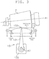
- FIG. 3 is an enlarged view of proximity of a traverse device of the yarn winding device;
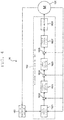
- FIG. 4 is a view illustrating a control configuration of a traverse control section;
- FIG. 5 is a view illustrating one example of a traverse profile and a rotation speed command according to a first embodiment;
- FIG. 6 is a flowchart illustrating an operation of the traverse device;
- FIG. 7 is a view illustrating a package hardness distribution; and
- FIG. 8 is a view illustrating one example of a traverse profile and a rotation speed command according to a second embodiment.
DETAILED DESCRIPTION OF PREFERRED EMBODIMENTS
1. First Embodiment
(1) Structure of automatic winder
-
Hereinafter, a description will be made on a structure of an automatic winder 100 including a yarn winding device 1 according to a first embodiment using FIG. 1.
-
The automatic winder 100 includes a plurality of yarn winding devices (winding units) 1 arranged side by side. Each yarn winding device 1 is adapted to wind a yarn Y unwound from a yarn supplying bobbin B1 around a winding bobbin B2 (to be described later) to form a package P in which the yarn Y is wound. Details on the structure of the yarn winding device 1 according to the present embodiment will be described in detail later.
-
The automatic winder 100 includes an automatic doffing device 3. The automatic doffing device 3 is adapted to travel up to a position of the relevant yarn winding device 1 to collect the fully wound package P and to also supply an empty winding bobbin B2 when the package P is fully wound in each yarn winding device 1.
-
The automatic winder 100 includes a machine setting device 5. The machine setting device 5 is, for example, a computer system including a CPU, a storage device (RAM, ROM, etc.), and various types of interfaces, and mainly includes a setting section 51 and a display section 52. The setting section 51 enables an operator to input a predetermined set value or select an appropriate control method to carry out setting with respect to each yarn winding device 1. An input device with a plurality of keys, for example, can be used for the setting section 51. A touch panel may also be used for the setting section 51.
-
The display section 52 is configured to be able to display a winding status of the yarn Y in each yarn winding device 1, content of trouble that occurred in the automatic winder 100, and the like. A display such as a liquid crystal display, and the like, for example, can be used for the display section 52.
-
The automatic winder 100 includes a machine control section 7. The machine control section 7 is, for example, a computer system including a CPU, a storage device (RAM, ROM, etc.), and various types of interfaces, and executes a control relating to the entire automatic winder 100 such as control of the automatic doffing device 3, and the like. The machine setting device 5 and the machine control section 7 may be configured as a same section.
(2) Structure of yarn winding device
-
Next, a description will be made on the details on the structure of the yarn winding device 1 according to the present embodiment using FIG. 2.
-
The yarn winding device 1 includes a cradle 11. The cradle 11 is a member adapted to rotatably and removably support the winding bobbin B2 for forming a conical (to be described later) package P about a predetermined axis A1 (FIG. 3). As illustrated in FIG. 2, the predetermined axis A1, which is a rotational axis of the winding bobbin B2, forms a predetermined angle with respect to an outer peripheral surface of a contact roller 14 (to be described later) so that a side facing the contact roller 14 of the winding bobbin B2 becomes parallel to the outer peripheral surface of the contact roller 14. A width direction of the package P to be described later can also be said as an axial direction of the contact roller 14.
-
The cradle 11 can be swung with a swing shaft A2 as the center. The cradle 11 thus can be swung with the swing shaft A2 as the center and absorb the increase in diameter involved with the winding of the yarn Y around the winding bobbin B2.
-
Furthermore, an angle sensor SE1 adapted to detect a swing angle of the cradle 11 is attached to the swing shaft A2. The angle sensor SE1 is, for example, a rotary encoder, and transmits a signal corresponding to the swing angle of the cradle 11 about the swing shaft A2 to a unit control section 15 (to be described later).
-
Since the swing angle of the cradle 11 about the swing shaft A2 changes as the package P becomes thicker with winding, a diameter of the package P can be detected by detecting the swing angle with the angle sensor SE1.
-
In other embodiments, a method for acquiring the diameter of the package P is not limited to the method described above. For example, the diameter of the package P may be calculated based on a rotation number, a winding speed, and a winding angle of the package P. The diameter of the package P thus can be calculated even if the angle sensor SE1 is not arranged.
-
The yarn winding device 1 includes a package drive motor 12. The package drive motor 12 is attached to a portion sandwiching the winding bobbin B2 of the cradle 11, and rotates the winding bobbin B2 about the predetermined shaft A1 to wind the yarn Y around the winding bobbin B2. A motor shaft of the package drive motor 12 is coupled with the winding bobbin B2 so as to be relatively non-rotatable when the winding bobbin B2 is supported by the cradle 11 (direct drive type).
-
The yarn winding device 1 includes a traverse device 13. The traverse device 13 is adapted to traverse the yarn Y along the width direction of the package P with respect to the winding bobbin B2 rotating about the predetermined axis A1. As illustrated in FIG. 3, the traverse device 13 according to the present embodiment mainly includes a traverse arm 131, a traverse guide 133, and a traverse motor 135.
-
The traverse arm 131 is a tapered rod shaped member. The traverse guide 133 is a member including a hook capable of hooking the yarn Y, and is attached to a narrowed distal end of the traverse arm 131. The traverse motor 135 is configured by, for example, a servo motor. A base portion of the traverse arm 131 (side opposite from the side the traverse guide 133 is attached in the traverse arm 131) is fixed to an output shaft A3 of the traverse motor 135.
-
In other embodiments, the traverse arm 131 may not be formed to a tapered shape. The traverse guide 133 may not be a hook type, and may be formed to, for example, a U type, a V type, or an O type. The traverse guide 133 merely needs to be able to make contact with the yarn Y and traverse the yarn along the width direction of the package. The traverse arm 131 and the traverse guide 133 may be integrated.
-
The traverse motor 135 is controlled to forward rotate or reverse rotate the output shaft A3 within a predetermined angle range and at a predetermined cycle by a traverse drive control section 162, to be described later. The traverse motor 135 is configured so that a rotating direction (forward rotation or reverse rotation) switches at both end positions in the width direction of the package P with a position corresponding to a central position in the width direction of the package P as an origin.
-
As illustrated in FIG. 3, the traverse guide 133 attached to the distal end of the traverse arm 131 reciprocates (traverses) between a first end (one end) and a second end (other end) of a traverse path along an arcuate traverse path (path illustrated with a dotted line in FIG. 3) extending in the direction along the width direction of the package P by repeating the forward rotation and the reverse rotation of the output shaft A3 of the traverse motor 135.
-
As illustrated in FIG. 3, the first end of the traverse path exists in proximity to one end in the width direction of the package P, and the second end exists in proximity to the other end in the width direction of the package P. In other words, the first end corresponds to one end (smaller diameter end) in the width direction of the package P, and the second end corresponds to the other end (larger diameter end) in the width direction of the package P.
-
The traverse guide 133 guides the yarn Y (i.e., yarn Y at a contacting point of the traverse guide 133 and the yarn Y) hooked at the hook portion to a predetermined position on the traverse path by the reciprocate movement to guide the yarn to a position corresponding to the predetermined position in the width direction of the winding bobbin B2 or the package P.
-
As described above, the traverse guide 133 moves along the traverse path according to the rotation of the output shaft A3 of the traverse motor 135, and thus the traverse position defined as a position of the traverse guide 133 on the traverse path can correspond with a rotation position of the output shaft A3 of the traverse motor 135.
-
The yarn winding device 1 includes the contact roller 14 attached to make contact with the outer peripheral surface of the winding bobbin B2 or the outer peripheral surface of the package P and to be driven rotated. The contact roller 14 is adapted to push the yarn Y guided by the traverse guide 133 against the outer peripheral surface of the winding bobbin B2 or the outer peripheral surface of the package P at a predetermined pressure to wind the yarn Y around the outer peripheral surface of the winding bobbin B2 or the package P.
-
The yarn winding device 1 includes the unit control section 15. The unit control section 15 is, for example, a computer system configured by a CPU, a storage device (RAM, ROM), and various types of interfaces. The unit control section 15 is connected to each structure of the yarn winding device 1, and is adapted to carry out the control of the yarn winding device 1.
-
A program for realizing the control (one part of or all of the control) of each structure of the yarn winding device 1 may be stored in the storage device of the unit control section 15. Furthermore, each function (one part thereof) of the unit control section 15 may be realized as hardware by SoC (System on Chip), and the like.
-
The unit control section 15 is connected to the machine setting device 5, and enables a set value relating to the control of the yarn winding device 1 set by the setting section 51 to be input. Furthermore, the unit control section 15 outputs information (e.g., error information) relating to an operation status of the yarn winding device 1 to the machine setting device 5. Thus, the information relating to the operation status of the yarn winding device 1 can be displayed on the display section 52.
-
The yarn winding device 1 includes a traverse control section 16. The traverse control section 16 is, for example, configured by hardware and the like by a dedicated microprocessor such as SoC. The traverse control section 16 is adapted to control the forward rotation or the reverse rotation of the traverse motor 135 based on a command of the unit control section 15, and the like. Detailed configuration of the traverse control section 16 will be described in detail later.
-
The traverse control section 16 may be, for example, a computer system configured by a CPU, a storage device (RAM, ROM), and various types of interfaces. In this case, each function of the traverse control section 16 may be realized by a program stored in the storage device of the computer system.
-
The yarn winding device 1 includes a package drive control section 17. The package drive control section 17 is, for example, a computer system configured by a CPU, a storage device (RAM, ROM), and various types of interfaces. The package drive control section 17 is adapted to control the rotation of the package drive motor 12 around the predetermined axis A1 upon receiving an operation signal from the unit control section 15.
-
For example, the package drive control section 17 can receive a signal notifying the start of manufacturing of the package P from the unit control section 15, and start the rotation of the package drive motor 12. On the other hand, for example, the rotation of the package drive motor 12 can be stopped when the diameter of the package P reaches a predetermined size and a signal for ending the manufacturing of the package P is received from the unit control section 15.
-
A program for realizing the control (one part of or all of the control) of the package drive motor 12 may be stored in the storage device of the package drive control section 17. Furthermore, each function (one part thereof) of the package drive control section 17 may be realized as hardware by SoC, and the like.
-
In the description made above, the unit control section 15, the traverse control section 16, and the package drive control section 17 are configured by individual hardware (computer system, etc.). This is not the sole case, and the functions of the three control sections may be realized by one computer system (program stored therein) or hardware such as SoC. In other words, the functions of the three control sections may be integrated in one computer system or hardware such as SoC. Alternatively, the functions of two control sections out of the three control sections may be integrated in one computer system or hardware such as SoC.
-
The yarn winding device 1 may include a yarn unwinding assisting device 18. The yarn unwinding assisting device 18 is adapted to assist unwinding of the yarn from the yarn supplying bobbin B1 by lowering a regulating member covering a core tube of the yarn supplying bobbin B1 accompanying the unwinding of the yarn from the yarn supplying bobbin B1.
-
The yarn winding device 1 may include a tension applying device 19. The tension applying device 19 is adapted to apply a predetermined tension to the travelling yarn Y. The tension applying device 19 may be, for example, a gate-type tension applying device in which movable comb teeth are arranged with respect to fixed comb teeth.
-
The yarn winding device 1 may include a clearer 20. The clearer 20 is adapted to detect a yarn defect such as slub by monitoring a yarn thickness signal from a sensor adapted to detect the thickness of the yarn Y. A cutter adapted to immediately cut the yarn Y when a yarn defect is detected is provided in proximity to a clearer head where the sensor is arranged.
-
The yarn winding device 1 may also include a yarn joining device 21. The yarn joining device 21 is adapted to join a lower yarn from the yarn supplying bobbin B1 and an upper yarn from the package P after the clearer 20 detects a yarn defect and cuts the yarn, after yarn breakage during unwinding of the yarn from the yarn supplying bobbin B1, and the like. The yarn joining device may be a mechanical-type knotter, or a splicer that uses fluid such as compressed air.
-
A lower yarn guiding device 22 adapted to catch the lower yarn from the yarn supplying bobbin B1 and guide the lower yarn to the yarn joining device 21, and an upper yarn guiding device 23 adapted to catch the upper yarn from the package P and guide the upper yarn to the yarn joining device 21 may be provided on a lower side and an upper side of the yarn joining device 21, respectively. A suction port is formed at the distal end of the lower yarn guiding device 22, and a suction mouth is formed at the distal end of the upper yarn guiding device 23, where a suction flow is generated at the suction port and the suction mouth to suck and catch the yarn ends of the upper yarn and the lower yarn.
(3) Control configuration of traverse control section
-
Next, a description will be made on the control configuration of the traverse control section 16 using FIG. 4.
-
The traverse control section 16 includes a profile calculating section 161. The profile calculating section 161 is adapted to calculate a traverse profile, and outputs the same to the traverse drive control section 162. The traverse profile is a profile defining a traverse position of the traverse guide 133 at a predetermined time. The traverse profile assumes either one of a first end position or a second end position as a starting point and the other end position as an ending point, the first end position being a traverse position corresponding to one end (first end) (i.e., one end in the width direction of the package P) of the traverse path, and the second end position being a traverse position corresponding to the other end (second end) (i.e., other end in the width direction of the package P) of the traverse path. A specific calculation method of the traverse profile will be described in detail later.
-
The traverse control section 16 includes the traverse drive control section 162. The traverse drive control section 162 is adapted to control the traverse motor 135 based on the traverse profile calculated in the profile calculating section 161.
-
The traverse drive control section 162 of the present embodiment feeds back an actual rotation angle (corresponds to the traverse position of the traverse guide 133) of the traverse motor 135, and feedback controls the traverse motor 135 based on a comparison between the actual rotation angle and a rotation angle corresponding to the position of the yarn Y indicated in the traverse profile.
-
Specifically, the traverse drive control section 162 includes a profile storage section 1621. The profile storage section 1621 is a part of a storage region of the storage device of the computer system configuring the traverse control section 16, and is adapted to store the traverse profile calculated in the profile calculating section 161.
-
The traverse drive control section 162 includes a first deviation arithmetic section 1622. The first deviation arithmetic section 1622 is adapted to calculate a deviation of the traverse position (rotation position of the traverse motor 135 corresponding thereto) indicated in the traverse profile input from the profile storage section 1621, and the actually measured rotation angle of the traverse motor 135. The actual rotation angle of the traverse motor 135 can, for example, be measured by a rotary encoder attached to the output shaft A3.
-
The traverse drive control section 162 includes a position control section 1623. The position control section 1623 is adapted to generate a rotation speed command of the traverse motor 135 based on the deviation calculated by the first deviation arithmetic section 1622. The position control section 1623, for example, generates the rotation speed command by PI control or PID control using the deviation and a gain set in advance.
-
The traverse drive control section 162 includes a second deviation arithmetic section 1624. The second deviation arithmetic section 1624 is adapted to calculate a deviation of a rotation speed of the traverse motor 135 indicated in the rotation speed command output from the position control section 1623, and the actually measured rotation speed of the traverse motor 135. The actual rotation speed of the traverse motor 135 can, for example, be calculated as an amount of change per unit time of the value of the rotary encoder attached to the output shaft A3.
-
The traverse drive control section 162 includes a speed control section 1625. The speed control section 1625 is adapted to generate a current command based on the deviation calculated by the second deviation arithmetic section 1624. The speed control section 1625, for example, generates a current command signal by PI control or PID control using the deviation of the rotation speed command and the actual rotation speed, and the gain set in advance.
-
The traverse drive control section 162 includes a third deviation arithmetic section 1626. The third deviation arithmetic section 1626 is adapted to calculate a deviation of a current value indicated in the current command output from the speed control section 1625 and the actually measured current value output to the traverse motor 135.
-
The traverse drive control section 162 includes a current control section 1627. The current control section 1627 is adapted to generate a voltage command to input to a PWM section 1628 (to be described later) based on the deviation calculated by a third deviation arithmetic section 1626. The current control section 1627, for example, generates a voltage command by PI control or PID control using the deviation of the current command and the actual current value and the gain set in advance.
-
The traverse drive control section 162 includes the PWM section 1628. The PWM section 1628 is adapted to generate a pulse voltage in which a duty ratio is changed according to the voltage command output from the current control section 1627 by PWM (Pulse Width Modulation), and outputs the same to the traverse motor 135.
(4) Traverse profile
-
Hereinafter, a description will be made on the traverse profile used to control the traverse motor 135 in the traverse drive control section 162 of the present embodiment, using FIG. 5. In the following description, as illustrated in FIG. 3, an intermediate point of the first end and the second end of the traverse path is assumed as an origin of the traverse position of the traverse guide 133, a direction from the origin toward the second end (direction from the first end toward the second end) is assumed as a positive direction, and a direction from the origin toward the first end (direction from the second end toward the first end) is assumed as a negative direction.
-
FIG. 5 illustrates the traverse profile and the rotation speed command for one cycle in which the traverse guide 133 is moved from the first end position to the second end position and then returned back from the second end position to the first end position.
-
In the present embodiment, the traverse drive control section 162 controls the traverse motor 135 based on the traverse profile and the rotation speed command illustrated in FIG. 5.
-
In an example of the rotation speed command illustrated in FIG. 5(B), an absolute value of the traverse speed, which is a moving speed of the traverse guide 133, continuously and linearly decreases or increases as the traverse guide 133 moves from the first end position to the second position or in the reverse direction thereto at the traverse central part corresponding to at least the central region of the package P. The first end position of the traverse guide 133 corresponds to the smaller diameter end of the conical package P, and the second end position of the traverse guide 133 corresponds to the larger diameter end of the conical package P.
-
The rotation speed command in which the traverse speed linearly decreases or increases as the traverse guide 133 moves from the first end position to the second end position (as time elapses) is generated when, for example, the traverse profile in which the amount of change of the traverse position per unit time of the traverse guide 133 (differential value of the traverse profile at each time) decreases or increases with elapse of time is used.
-
Specifically, for example, as illustrated in FIG. 5A, the rotation speed command can be calculated from the traverse profile (this traverse profile is referred to as "first traverse profile") including a function with respect to time that is convex upward while the traverse guide 133 moves from the first end position to the second end position and returns from the second end position to the first end position (elapse of time).
-
The traverse profile can, for example, be defined by acceleration start time, acceleration end time, half-stroke time, deceleration start time, deceleration end time, one stroke time, acceleration end speed or acceleration, speed at traverse origin, deceleration start speed or deceleration, acceleration distance, deceleration distance, distance from traverse one end to traverse origin, and distance from traverse origin to traverse other end.
-
In the present embodiment, the traverse profile assumes a profile representing a relationship of the (a plurality of) traverse position where the traverse guide 133 reaches while the traverse guide 133 moves from the first end position to the second end position, and a time at which the yarn Y reaches the respective traverse position, or a profile representing a relationship of the (a plurality of) traverse position where the traverse guide 133 reaches while the traverse guide 133 moves from the second end position to the first end position, and a time at which the traverse guide 133 reaches the respective traverse positions as one unit. In other words, one of either the first end position, which is the traverse position corresponding to the first end of the traverse path, or the second end position, which is the traverse position corresponding to the second end of the traverse path, is the starting point of the traverse profile and the other position is the ending point of the traverse profile. Therefore, in FIG. 5A, the traverse profile in which the traverse position of the traverse guide 133 moves from the first end position toward the second end position, and the traverse profile in which the traverse position of the traverse guide 133 moves from the second end position toward the first end position with elapse of time are included.
-
Furthermore, as illustrated in FIGS. 5A and 5B, it can be seen that the traverse profile and the rotation speed command continuously change at the time, when the traverse guide 133 passes the origin (in FIG. 5, timing (time t1 and t3) indicated with a chain dashed line).
-
Furthermore, the plus/minus sign of the rotation speed command value is inverted so as to correspond to the change in the moving direction of the traverse guide 133 at the timing the traverse guide 133 exists at the first end position or the second end position, that is, the timing the traverse speed of the traverse guide 133 becomes 0 and in the proximity thereof.
-
As described above, an area where the winding state of the yarn Y rapidly changes can be avoided from generating during one stroke of traverse by calculating the traverse profile of changing the rotation speed command at the traverse position corresponding to one end or the other end (or proximity thereof) of the package P rather than at the central part of the package corresponding to the position (central region in the width direction of the package P) between one end and the other end of the package P.
(5) Operation of traverse device
-
Hereinafter, a description will be made on the operation of the traverse device 13 of the yarn winding device 1 according to the present embodiment using FIG. 6.
-
In the following description, assume that a cycle in which the traverse guide 133 moves from the first end position to the second end position, and thereafter returns from the second end position to the first end position is defined as one cycle of movement of the traverse guide 133, and nth (n: positive integer) cycle of the traverse has started. In other words, one round of the traverse stroke is assumed as one cycle of traverse.
-
The manufacturing conditions, and the like of the package P are set using the setting section 51 of the machine setting device 5 or the input device (e.g., key, touch panel, etc.) arranged in the unit control section 15, as necessary, and after (empty winding bobbin B2 is supplied) the manufacturing of the package P has started, last half of the n - 1th traverse cycle is executed, where when the traverse position of the traverse guide 133 reaches the first end position, the traverse drive control section 162 controls the traverse motor 135 based on "an 2n - 1th traverse profile (e.g., traverse profile from time 0 to t2 of FIG. 5A) having the first end position of the traverse position as the starting point and the second end position of the traverse position as the ending point" (step S1).
-
Thus, the first half of the nth traverse cycle (e.g., traverse stroke of first half of third cycle, in other words, fifth traverse stroke) is assumed to have started.
-
The 2n - 1th (e.g., fifth) traverse profile is calculated before the traverse guide 133 reaches the first end position from the second end position in the second half of the n - 1th traverse cycle (e.g., traverse stroke of the second half of the second cycle, in other words, during fourth traverse stroke), and stored in the profile storage section 1621.
-
As the traverse motor 135 is controlled based on the 2n - 1th (e.g., fifth) traverse profile, the traverse guide 133 moves the yarn Y from the first end position to the second end position while reducing the traverse speed.
-
After the traverse guide 133 has reached the first end position, the profile calculating section 161 calculates the 2nth traverse profile before the traverse guide 133 reaches the second end position (step S2).
-
Specifically describing, the "2nth (e.g., sixth) traverse profile" is calculated before the traverse position of the traverse guide 133 moves from the first end position to the second end position based on the "2n - 1th (e.g., fifth) traverse profile calculated in the second half of the traverse cycle immediately before". The calculated 2nth traverse profile is stored in the profile storage section 1621.
-
The 2nth traverse profile representing the movement of the traverse guide 133 from the next second end position to the first end position can, for example, be specifically calculated in the following manner.
-
First, the traverse width from the origin of the traverse position to the next first end position is calculated. Next, the 2nth traverse profile is calculated taking into consideration the traverse width from the origin of the traverse position to the second end position calculated at the time of calculation of the 2n - 1th traverse profile, the traverse width from the origin to the next first end position, and various types of conditions.
-
Then, during the movement of the traverse guide 133 from the first end position to the second end position, the traverse drive control section 162 determines whether or not the traverse guide 133 has reached the second end position (i.e., whether or not the traverse position of the traverse guide 133 has reached the second end position, whether or not the yarn Y has reached the other end of the package P) (step S3).
-
The traverse drive control section 162 can determine that the second end position is reached, that is, the traverse position of the traverse guide 133 has reached the second end position when, for example, the elapsed time from when the traverse guide 133 starts the movement from the first end position coincides with the time for the traverse guide 133 to move from the first end position to the second end position.
-
The time for the traverse guide 133 to move from the first end position to the second end position can be, for example, calculated based on a peripheral speed of the current (middle of being manufactured) package P, a traverse width, and a winding angle of the yarn Y, or a wind number (winding number) of the yarn Y into the package P.
-
In addition, the traverse drive control section 162 may determine that the traverse position of the traverse guide 133 reached the second end position when, for example, a measurement value of the rotation angle of the transverse motor 135 is detected to be the rotation angle corresponding to the second end position of the traverse position.
-
When the traverse position of the traverse guide 133 reached the second end position (when "Yes" in step S3), and for example, when the diameter of the package P is smaller than the set value set in advance and determination is made to continue the winding of the yarn Y into the package P (when "No" in step S4), the traverse drive control section 162 starts the control of the traverse motor 135 based on the "2nth (e.g., sixth) traverse profile (e.g., traverse profile from time t2 to t4 in FIG. 5A) having the second end position of the traverse position as the starting point and the first end position of the traverse position as the ending point" (step S5).
-
The second half of the nth traverse cycle is thereby started.
-
The profile calculating section 161 calculates the 2n + 1th traverse profile and stores the same in the profile storage section 1621 after the traverse guide 133 has reached the second end position by the control of the traverse motor 135 based on the 2n - 1th (e.g., fifth) traverse profile and before the traverse guide 133 reaches the first end position from the second end position by the control of the traverse motor 135 based on the 2nth (e.g., sixth) traverse profile (step S6).
-
The 2n + 1th traverse profile representing the movement of the traverse guide 133 from the next first end position to the second end position can, for example, be specifically calculated in the following manner.
-
First, the traverse width from the origin of the traverse position to the next second end position is calculated. Next, the 2n + 1th traverse profile is calculated taking into consideration the traverse width from the origin of the traverse position to the first end position calculated at the time of calculation of the 2nth traverse profile, the traverse width from the origin to the next second end position, and various types of conditions.
-
The 2n + 1th (e.g., seventh) traverse profile represents the traverse from the first end position to the second end position in the first half of the n + 1th traverse cycle (first half of fourth cycle).
-
During the movement of the traverse guide 133 from the second end position to the first end position, the traverse drive control section 162 determines whether or not the traverse guide 133 has reached the first end position (i.e., whether or not the traverse position of the traverse guide 133 has reached the first end position, in other words, whether or not the traverse position corresponding to one end of the package P is reached) (step S7).
-
When the traverse position of the traverse guide 133 reached the first end position (when "Yes" in step S7), for example, when the diameter of the package P is smaller than the set value set in advance and determination is made to continue the winding of the yarn Y into the package P (when "No" in step S8), n = n + 1 is realized (i.e., one cycle of next traverse is started) (step S9), and then the process is returned to step S1. For example, when the diameter of the package P is greater than or equal to the set value set in advance and determination is made that the winding of the yarn Y into the package P is completed (when "Yes" in step S8), the present control is terminated.
-
The steps S1 to S9 described above are repeatedly executed until the package P is fully wound (i.e., until determined "Yes" in step S3 or step S8).
-
When forming the conical package P by repeatedly executing the steps S1 to S9, the profile calculating section 161 calculates a first traverse profile that realizes a speed pattern in which the absolute value of the traverse speed continuously decreases as the traverse guide 133 moves from the first end position to the second end position and continuously increases as the traverse guide 133 moves from the second end position to the first end position at the central part of the package corresponding to the central region of the package P, as illustrated in FIG. 5A, for example, whereby when the traverse drive control section 162 controls the traverse motor 135 based on the first traverse profile, a high quality conical package P whose package hardness continuously becomes larger from the smaller diameter toward the larger diameter of the package P, as illustrated in FIG. 7, is manufactured.
-
In other words, as the portion of high package hardness tends to easily become the drive point, the occurrence of stitching can be better avoided by stabilizing the drive point on the larger diameter side where the hardness is high to manufacture a high quality package P.
-
As illustrated as "comparative example" of FIG. 7, when manufacturing the conical package P while executing the switching of the traverse profile at the central position of the package P, the traverse speed is rapidly switched at the central position and the package hardness is rapidly changed at the central position of the package P.
-
In the yarn winding device 1, when the traverse position has reached the first end position or the second end position corresponding to the end in the width direction of the package, the traverse drive control section 162 starts the control of the traverse motor 135 based on the traverse profile having the reached first end position or the second end position as the starting point.
-
Thus, the traverse speed at the central region in the width direction of the package can be controlled to a desired speed pattern by calculating the traverse profile having the end in the width direction of the package as the starting point, whereby the traverse speed can be prevented from rapidly changing at the central region of the package. The drive point thus can be stabilized, and "stitching" can be avoided from occurring in the manufacturing process of the package P. As a result, a high quality package P can be manufactured.
-
Furthermore, the profile calculating section 161 calculates the first traverse profile that realizes a speed pattern in which the traverse speed, which is the moving speed of the traverse guide 133, continuously increases or decreases as the traverse guide 133 moves from the first end position to the second end position and continuously decreases or increases as the traverse guide 133 moves from the second end position to the first end position at the traverse central part corresponding to the central region in the width direction of the package P. Furthermore, the traverse drive control section 162 controls the traverse motor 135 based on the first traverse profile when forming the conical package whose diameter decreases or increases from one end toward the other end.
-
Thus, a high quality conical package P can be manufactured.
-
Moreover, after the traverse position of the traverse guide 133 is moved from the first end position to the second end position, the profile calculating section 161 calculates the next traverse profile representing the traverse from the first end position to the second end position before the first end position is reached based on the most recently calculated traverse profile representing the traverse from the second end position to the first end position.
-
Thus, every time the yarn Y reaches the package end, the next traverse profile is calculated before the opposite end is reached based on the most recently calculated traverse profile, and the switch to the control of the traverse motor 135 based on the next traverse profile is executed without delay, so that a high quality package P can be manufactured.
-
The traverse motor 135 is configured such that the rotating direction is switched at the first end position and the second end position in the width direction of the package P while having the position corresponding to the central position in the width direction of the package P as the origin. Furthermore, the traverse drive control section 162 forward rotates the traverse motor 135 to move the traverse guide 133 from one of the first end position or the second end position to the other end position, and reverse rotates the traverse motor 135 to move the traverse guide 133 from the other one of the first end position or the second end position to the one end position.
-
Thus, even in a mechanism in which the origin of the traverse motor 135 corresponds to the central position in the width direction of the package, the control based on the traverse profile having the package end not corresponding to the origin of the traverse motor 135 as the starting point may be realized to manufacture a high quality package P.
-
The position at the end in the width direction of the package is not constant in the forming process of the package P and may change. The present invention can realize the traverse control having the position at the end in the width direction of the package that changes in such manner as the starting point to manufacture a high quality package P.
2. Second Embodiment
-
The control method of the traverse motor 135 by steps S1 to S9 described in the first embodiment can also be applied to the manufacturing of a cylindrical shaped package in which the diameter is constant from one end to the other end of the package P.
-
In a yarn winding device according to a second embodiment for manufacturing a cylindrical shaped package, a winding bobbin having a circular column shape is used, and a predetermined shaft, which is a rotation shaft of the winding bobbin, is made parallel with respect to the width direction of the package P.
-
The profile calculating section 161 calculates a second traverse profile that realizes a speed pattern in which the traverse speed, which is the moving speed of the traverse guide 133, is constant while the traverse guide 133 moves from one of the first end position and the second end position to the other end position, and from the other end position to the one end position at the traverse central part corresponding to the central region in the width direction of the package P.
-
The traverse drive control section 162 is adapted to control the traverse motor 135 based on the second traverse profile when manufacturing the cylindrical shaped package P.
-
Specifically, as illustrated in FIG. 8A, the second traverse profile is a profile for linearly moving the traverse guide 133 with respect to time from the first end position to the second end position or from the second end position to the first end position of the traverse position (from the traverse position corresponding to one end of the package P to the traverse position corresponding to the other end, or from the traverse position corresponding to the other end to the traverse position corresponding to the one end).
-
A rotation speed command in which the traverse speed is constant from the first end position to the second end position of the traverse position is generated at the traverse central part corresponding to at least the central region of the package P, as illustrated in FIG. 8B, by using the second traverse profile in the control of the traverse motor 135.
-
Other than that the shape of the winding bobbin is cylindrical, the predetermined shaft is parallel to the contact roller 14, and the traverse profile used in the control of the traverse motor 135 is the second profile, the structures and functions of other configuring components of the yarn winding device are the same as the yarn winding device 1 according to the first embodiment.
-
The profile calculating section 161 calculates the traverse profile as illustrated in FIG. 8A, and the traverse drive control section 162 controls the traverse motor 135 based on the relevant traverse profile and executes the switching of the traverse profile at the traverse position (first end position, second end position) corresponding to the end of the package, so that the manufacturing of a high quality cylindrical shaped package P is facilitated.
-
Even when manufacturing the cylindrical shaped package P, for example, when carrying out a creeping operation, the adjustment of the traverse speed is sometimes necessary at the right and left of the traverse, where in the conventional control, the traverse speed sometimes discontinuously changes (step sometimes forms in the traverse speed) at the traverse position corresponding to the central position of the package P. However, according to the present embodiment, a traverse profile having one of the first end position or the second end position of the traverse position as the starting point and the other end position as the ending point is created and the switching is executed at the first end position or the second end position, whereby adjustment can be easily made so that the traverse speed does not discontinuously change at the central position, and even in the case described above, a high quality cylindrical shaped package P can be manufactured.
3. Common subject matter of embodiments
-
The first and second embodiments have the following structure and function in common.
-
The yarn winding device 1 (one example of yarn winding device) according to the first and second embodiments includes the traverse guide 133 (one example of traverse guide), the traverse motor 135 (one example of traverse motor), the profile calculating section 161 (one example of profile calculating section), and the traverse drive control section 162 (one example of traverse drive control section). The traverse guide 133 is adapted to make contact with the yarn Y (one example of yarn), and traverse the yarn Y along the width direction of the package P (one example of package). The traverse motor 135 is adapted to drive the traverse guide 133.
-
The profile calculating section 161 is adapted to calculate the traverse profile. The traverse profile is a profile defining a traverse position of the traverse guide 133 at a predetermined time. The traverse profile assumes either one of a first end position or a second end position as a starting point, and the other end position as an ending point. The first end position is a traverse position corresponding to one end in a width direction of the package. The second end position is a traverse position corresponding to the other end in the width direction of the package.
-
The traverse drive control section 162 is adapted to control the traverse motor 135 based on the traverse profile calculated in the profile calculating section 161. The traverse drive control section 162 starts the control of the traverse motor 135 based on the traverse profile having the first end position as the starting point when the traverse position of the traverse guide 133 has reached the first end position. The traverse drive control section 162 starts the control of the traverse motor 135 based on the traverse profile having the second end position as the starting point when the traverse position of the traverse guide 133 has reached the second end position.
-
In the yarn winding device 1, when the traverse guide 133 has reached the first end position and the second end position corresponding to the end in the width direction of the package, the traverse drive control section 162 starts the control of the traverse motor 135 based on the traverse profile having the reached first end position or the second end position as the starting point.
-
Thus, the traverse speed at the central region in the width direction of the package can be controlled to a desired speed pattern by calculating the traverse profile having the end in the width direction of the package as the starting point, whereby the traverse speed can be prevented from rapidly changing at the traverse position corresponding to the central region of the package. Therefore, the winding state (yarn diamond of yarn, package hardness, etc.) of the yarn Y can be prevented from rapidly changing in the central region of the package P. Furthermore, the drive point can be stabilized, and "stitching" can be avoided from occurring in the manufacturing process of the package. As a result, a high quality package P can be manufactured.
4. Other Embodiment
-
A plurality of embodiments of the present invention have been described, but the present invention is not limited to the above-described embodiments, and various changes can be made within a scope not departing from the claims of the invention. In particular, a plurality of embodiments and alternative embodiments described in the specification can be arbitrarily combined, as necessary.
- (A) Each step (steps S1 to S9) indicating the operation of the traverse device 13 described in the first embodiment may have the content of the process appropriately changed and/or the order of the process of the step changed within a scope not deviating from the claims of the invention.
- (B) A traverse device other than the traverse device including the traverse arm 131, the traverse guide 133, and the traverse motor 135 described in the first embodiment may be used. For example, a traverse device including a cylindrical winding drum provided with a traverse groove adapted to be inserted with the yarn Y and to hold the yarn on a side surface in a length direction can be used. Furthermore, a belt type traverse device can be used. The belt type traverse device also includes a traverse guide adapted to make contact with the yarn and traverse the yarn along the width direction of the package, and a traverse motor adapted to drive the traverse guide. Moreover, the belt type traverse device can also be configured to forward rotate or reverse rotate with the central position in the width direction of the package as an origin.
In the traverse device including the winding drum described above, for example, the rotation angle and the rotation speed of the winding drum can be controlled based on the traverse profile described in the first and second embodiments, and the switching of the traverse profile can be executed when the rotation angle of the winding drum reaches an angle of when the yarn Y exists at the end of the package, so that a high quality package can be manufactured, similar to the first and second embodiments. - (C) The rotation speed command of the traverse motor 135 may include a trapezoidal rotation speed command pattern, for example, at a timing the traverse position of the traverse guide 133 is at the first end position or the second end position, or in proximity thereto. In other words, the traverse profile of the embodiments described above is a speed pattern including a speed increasing region, which is one end region, a central region, and a speed decreasing region, which is the other end region, but may be a speed pattern including a constant-speed region between the central region and each end region.