EP3441293A1 - Pedal-connecting mechanism and electric self-balancing scooter adopting same - Google Patents
Pedal-connecting mechanism and electric self-balancing scooter adopting same Download PDFInfo
- Publication number
- EP3441293A1 EP3441293A1 EP16889002.8A EP16889002A EP3441293A1 EP 3441293 A1 EP3441293 A1 EP 3441293A1 EP 16889002 A EP16889002 A EP 16889002A EP 3441293 A1 EP3441293 A1 EP 3441293A1
- Authority
- EP
- European Patent Office
- Prior art keywords
- pedal
- signal
- output end
- signal processor
- connecting mechanism
- Prior art date
- Legal status (The legal status is an assumption and is not a legal conclusion. Google has not performed a legal analysis and makes no representation as to the accuracy of the status listed.)
- Pending
Links
Images
Classifications
-
- B—PERFORMING OPERATIONS; TRANSPORTING
- B62—LAND VEHICLES FOR TRAVELLING OTHERWISE THAN ON RAILS
- B62K—CYCLES; CYCLE FRAMES; CYCLE STEERING DEVICES; RIDER-OPERATED TERMINAL CONTROLS SPECIALLY ADAPTED FOR CYCLES; CYCLE AXLE SUSPENSIONS; CYCLE SIDECARS, FORECARS, OR THE LIKE
- B62K23/00—Rider-operated controls specially adapted for cycles, i.e. means for initiating control operations, e.g. levers, grips
- B62K23/08—Rider-operated controls specially adapted for cycles, i.e. means for initiating control operations, e.g. levers, grips foot actuated
-
- B—PERFORMING OPERATIONS; TRANSPORTING
- B60—VEHICLES IN GENERAL
- B60K—ARRANGEMENT OR MOUNTING OF PROPULSION UNITS OR OF TRANSMISSIONS IN VEHICLES; ARRANGEMENT OR MOUNTING OF PLURAL DIVERSE PRIME-MOVERS IN VEHICLES; AUXILIARY DRIVES FOR VEHICLES; INSTRUMENTATION OR DASHBOARDS FOR VEHICLES; ARRANGEMENTS IN CONNECTION WITH COOLING, AIR INTAKE, GAS EXHAUST OR FUEL SUPPLY OF PROPULSION UNITS IN VEHICLES
- B60K1/00—Arrangement or mounting of electrical propulsion units
- B60K1/02—Arrangement or mounting of electrical propulsion units comprising more than one electric motor
-
- B—PERFORMING OPERATIONS; TRANSPORTING
- B62—LAND VEHICLES FOR TRAVELLING OTHERWISE THAN ON RAILS
- B62J—CYCLE SADDLES OR SEATS; AUXILIARY DEVICES OR ACCESSORIES SPECIALLY ADAPTED TO CYCLES AND NOT OTHERWISE PROVIDED FOR, e.g. ARTICLE CARRIERS OR CYCLE PROTECTORS
- B62J25/00—Foot-rests; Knee grips; Passenger hand-grips
- B62J25/04—Floor-type foot rests
-
- B—PERFORMING OPERATIONS; TRANSPORTING
- B62—LAND VEHICLES FOR TRAVELLING OTHERWISE THAN ON RAILS
- B62K—CYCLES; CYCLE FRAMES; CYCLE STEERING DEVICES; RIDER-OPERATED TERMINAL CONTROLS SPECIALLY ADAPTED FOR CYCLES; CYCLE AXLE SUSPENSIONS; CYCLE SIDECARS, FORECARS, OR THE LIKE
- B62K11/00—Motorcycles, engine-assisted cycles or motor scooters with one or two wheels
- B62K11/007—Automatic balancing machines with single main ground engaging wheel or coaxial wheels supporting a rider
-
- B—PERFORMING OPERATIONS; TRANSPORTING
- B62—LAND VEHICLES FOR TRAVELLING OTHERWISE THAN ON RAILS
- B62J—CYCLE SADDLES OR SEATS; AUXILIARY DEVICES OR ACCESSORIES SPECIALLY ADAPTED TO CYCLES AND NOT OTHERWISE PROVIDED FOR, e.g. ARTICLE CARRIERS OR CYCLE PROTECTORS
- B62J43/00—Arrangements of batteries
- B62J43/10—Arrangements of batteries for propulsion
- B62J43/16—Arrangements of batteries for propulsion on motorcycles or the like
-
- B—PERFORMING OPERATIONS; TRANSPORTING
- B62—LAND VEHICLES FOR TRAVELLING OTHERWISE THAN ON RAILS
- B62J—CYCLE SADDLES OR SEATS; AUXILIARY DEVICES OR ACCESSORIES SPECIALLY ADAPTED TO CYCLES AND NOT OTHERWISE PROVIDED FOR, e.g. ARTICLE CARRIERS OR CYCLE PROTECTORS
- B62J43/00—Arrangements of batteries
- B62J43/30—Arrangements of batteries for providing power to equipment other than for propulsion
-
- B—PERFORMING OPERATIONS; TRANSPORTING
- B62—LAND VEHICLES FOR TRAVELLING OTHERWISE THAN ON RAILS
- B62J—CYCLE SADDLES OR SEATS; AUXILIARY DEVICES OR ACCESSORIES SPECIALLY ADAPTED TO CYCLES AND NOT OTHERWISE PROVIDED FOR, e.g. ARTICLE CARRIERS OR CYCLE PROTECTORS
- B62J45/00—Electrical equipment arrangements specially adapted for use as accessories on cycles, not otherwise provided for
- B62J45/40—Sensor arrangements; Mounting thereof
- B62J45/41—Sensor arrangements; Mounting thereof characterised by the type of sensor
- B62J45/414—Acceleration sensors
-
- B—PERFORMING OPERATIONS; TRANSPORTING
- B62—LAND VEHICLES FOR TRAVELLING OTHERWISE THAN ON RAILS
- B62K—CYCLES; CYCLE FRAMES; CYCLE STEERING DEVICES; RIDER-OPERATED TERMINAL CONTROLS SPECIALLY ADAPTED FOR CYCLES; CYCLE AXLE SUSPENSIONS; CYCLE SIDECARS, FORECARS, OR THE LIKE
- B62K2202/00—Motorised scooters
-
- B—PERFORMING OPERATIONS; TRANSPORTING
- B62—LAND VEHICLES FOR TRAVELLING OTHERWISE THAN ON RAILS
- B62K—CYCLES; CYCLE FRAMES; CYCLE STEERING DEVICES; RIDER-OPERATED TERMINAL CONTROLS SPECIALLY ADAPTED FOR CYCLES; CYCLE AXLE SUSPENSIONS; CYCLE SIDECARS, FORECARS, OR THE LIKE
- B62K2204/00—Adaptations for driving cycles by electric motor
Definitions
- the present invention relates to the technical field of scooters, in particular to a pedal connecting mechanism and an electric balancing scooter employing the same.
- Electric balancing scooter also known as a motion-sensing scooter, Segway, etc.
- An electric balancing scooter is based on the principle of "dynamic stabilization", where the gyroscopes and acceleration sensors inside the scooter body are used to judge the posture state of the scooter body, and a precise and high-speed central microprocessor is used to calculate the appropriate commands, and the motors are driven to perform corresponding adjustments so as to maintain the balance of the system.
- the existing balancing scooters are in various and diverse forms.
- balancing scooters in the market which are equipped with a directional lever; during use, a user controls the direction of movement of the balancing scooter by adjusting the directional lever; the operation is complex, and the user may take great effort to adjust the directional lever. Moreover, the user needs to hold the directional lever by hand, and cannot do stretching and other actions at will, thereby reducing the fun of playing with the scooter.
- Chinese patent application number 201520567850 .X discloses a two-wheeled balancing scooter which can adjust the state of motion of the scooter without using a directional lever.
- the left and right pedals of the balancing scooter is connected via an intermediate shaft; during use, all the gravity of the human body is borne by the intermediate shaft; the twisting of the balancing scooter body would easily damage the intermediate shaft, or even cause the intermediate shaft to be broken; therefore such a structure for the balancing scooter is prone to failure, and has relatively low stability, reliability and safety.
- the balancing scooter designed with an intermediate shaft has a large reaction error.
- the present invention provides a pedal connecting mechanism, which is provided with a transverse connecting member at the bottoms of the left pedal and the right pedal, wherein the left pedal and the right pedal are not connected via an intermediate shaft, instead, they are two independent bodies, and their states of motion are independently controlled by the left foot and right foot, respectively; the transverse connecting member is used to distribute the gravity of human body and is uniformly stressed.
- This design is novel and reasonable, and is conducive to prolonging the service life.
- a further object of the present invention is to provide an electric balancing scooter employing the pedal connecting mechanism, which is provided with a transverse connecting member at the bottoms of the pedals.
- the transverse connecting member bears the gravity of the human body and is uniformly stressed, and damage to the structure of the balancing scooter is reduced, so that the balancing scooter has a good stability and is reliable and safe.
- a pedal connecting mechanism comprises a left pedal, a right pedal and a transverse connecting member, wherein a first cylindrical shaft is provided along the bottom of the left pedal; a first supporting member is provided on the left side of a top wall of the transverse connecting member, and a first groove matching the first cylindrical shaft is provided on the first supporting member; the first cylindrical shaft is provided inside the first groove so that the left pedal is rotatably connected to the first supporting member; a second cylindrical shaft is provided along the bottom of the right pedal; a second supporting member is provided on the right side of the top wall of the transverse connecting member, and a second groove matching the second cylindrical shaft is provided on the second supporting member; and the second cylindrical shaft is provided inside the second groove so that the right pedal is rotatably connected to the second supporting member.
- the first cylindrical shaft is composed of two transversely arranged first cylinders, which are symmetrically provided on two sides of the bottom of the left pedal; two first supporting members are correspondingly provided on the left side of the top wall of the transverse connecting member, and a first groove matching the first cylinder is provided on each of the first supporting members; the left pedal is rotatably connected to the first supporting members; the second cylindrical shaft is composed of two transversely arranged second cylinders, which are symmetrically provided on two sides of the bottom of the right pedal; two second supporting members are correspondingly provided on the right side of the top wall of the transverse connecting member, and a second groove matching the second cylinder is provided on each of the second supporting members; and the right pedal is rotatably connected to the second supporting members.
- the pedal connecting mechanism further comprises a first elastic member and a second elastic member, wherein one end of the first elastic member is connected to the bottom of the left pedal, and the other end thereof is correspondingly connected to the left side of the top wall of the transverse connecting member; and one end of the second elastic member is connected to the bottom of the right pedal, and the other end thereof is connected to the right side of the top wall of the transverse connecting member.
- the first elastic member and the second elastic member are both springs.
- the number of the first elastic members is four, and one end of each of the four first elastic members is respectively connected to each of the four corners of the bottom of the left pedal and the other end thereof is respectively connected to the left side of the top wall of the transverse connecting member; and the number of the second elastic members is four, and one end of each of the four second elastic members is respectively connected to each of the four corners of the bottom of the right pedal and the other end thereof is respectively connected to the right side of the top wall of the transverse connecting member.
- the transverse connecting member is a flat plate, two sides being symmetrically inwardly recessed at a middle part in a longitudinal direction of the flat plate.
- the number of the signal processors is one;
- the first sensing element comprises a first gyroscope and a first acceleration sensor; a signal output end of the first gyroscope is connected to a first signal input end of the signal processor; a signal output end of the first acceleration sensor is connected to a second signal input end of the signal processor;
- the second sensing element comprises a second gyroscope and a second acceleration sensor; a signal output end of the second gyroscope is connected to a third input end of the signal processor; and a signal output end of the second acceleration sensor is connected to a fourth input end of the signal processor.
- the number of the signal processors is two, which are denoted as a first signal processor and a second signal processor, respectively;
- the first sensing element comprises a first gyroscope and a first acceleration sensor; a signal output end of the first gyroscope is connected to a first signal input end of the first signal processor; a signal output end of the first acceleration sensor is connected to a second signal input end of the first signal processor;
- the second sensing element comprises a second gyroscope and a second acceleration sensor; a signal output end of the second gyroscope is connected to a first input end of the second signal processor; and a signal output end of the second acceleration sensor is connected to a second input end of the second signal processor.
- the number of the first touch sensing switches is two, and the number of the second touch sensing switches is two.
- a pedal connecting mechanism comprises left pedal 10, right pedal 20 and transverse connecting member 30, wherein a first cylindrical shaft 11 is centrally and transversely provided along the bottom of the left pedal 10; a first supporting member 31 is provided on the left side of a top wall of the transverse connecting member 30, and a first groove matching the first cylindrical shaft 11 is provided on the first supporting member 31; the first cylindrical shaft 11 is provided inside the first groove so that the left pedal 10 is rotatably connected to the first supporting member 31; a second cylindrical shaft 21 is centrally and transversely provided along the bottom of the right pedal 20; a second supporting member 32 is provided on the right side of the top wall of the transverse connecting member 30, and a second groove matching the second cylindrical shaft 21 is provided on the second supporting member 32; and the second cylindrical shaft 21 is provided inside the second groove so that the right pedal 20 is rotatably connected to the second supporting member 32.
- the first cylindrical shaft 11 is composed of two transversely arranged first cylinders, which are symmetrically provided on two sides of the bottom of the left pedal 10; two first supporting members 31 are correspondingly provided on the left side of the top wall of the transverse connecting member 30, and a first groove matching the first cylinder is provided on each of the first supporting members 31; the left pedal 10 is rotatably connected to the first supporting members 31; the second cylindrical shaft 21 is composed of two transversely provided second cylinders, which are symmetrically provided on two sides of the bottom of the right pedal 20; two second supporting members 32 are correspondingly provided on the right side of the top wall of the transverse connecting member 30, and a second groove matching the second cylinder is provided on each of the second supporting members 32; and the right pedal 20 is rotatably connected to the second supporting members 32.
- the pedal connecting mechanism further comprises a first elastic member 12 and a second elastic member 22, wherein one end of the first elastic member 12 is connected to the bottom of the left pedal 10, and the other end thereof is correspondingly connected to the left side of the top wall of the transverse connecting member 30; and one end of the second elastic member 22 is connected to the bottom of the right pedal 20, and the other end thereof is connected to the right side of the top wall of the transverse connecting member 30.
- the first elastic member 12 and the second elastic member 22 may be both provided as, but not limited to, springs, and may be provided as other suitable elastic members.
- the elastic members allow the user to feel cushioned to a certain extent after stepping on the pedals, thereby increasing the comfort.
- the number of first elastic members 12 is four, and one end of each of the four first elastic members 12 is respectively connected to each of the four corners of the bottom of the left pedal 10 and the other end thereof is respectively connected to the left side of the top wall of the transverse connecting member 30; and the number of second elastic members 22 is four, and one end of each of the four second elastic members 22 is respectively connected to each of the four corners of the bottom of the right pedal 20 and the other end thereof is respectively connected to the right side of the top wall of the transverse connecting member 30.
- the transverse connecting member 30 may be provided as a flat plate, two sides being symmetrically inwardly recessed at a middle part in a longitudinal direction of the flat plate.
- the transverse connecting member 30 is provided at the bottoms of the left pedal 10 and the right pedal 20, the left pedal 10 and the right pedal 20 are respectively rotatably connected to the transverse connecting member 30, and the left pedal 10 and the right pedal 20 are independent of each other; when the balancing scooter is in use, the gravity applied by the human body to the pedals is transmitted to the transverse connecting member 30, the transverse connecting member 30 bears the gravity of the human body and is uniformly stressed, avoiding the drawback that an intermediate shaft, which is used to connect the left pedal with the right pedal of the balancing scooter of the prior art and bears the gravity of the human body, is easily worn or even broken.
- the balancing scooter made by using this pedal connecting mechanism is reliable, safe and durable. Furthermore, the pedal connecting mechanism can be applied not only to a double-wheeled balancing scooter, but also to a three-wheeled balancing scooter, a four-wheeled balancing scooter, a six-wheeled balancing scooter or other suitable types of scooters, and has a wide range of applications, strong practicality, and great business prospects.
- the number of signal processors is one; the first sensing element comprises a first gyroscope and a first acceleration sensor; a signal output end of the first gyroscope is connected to a first signal input end of the signal processor; a signal output end of the first acceleration sensor is connected to a second signal input end of the signal processor; the second sensing element comprises a second gyroscope and a second acceleration sensor; a signal output end of the second gyroscope is connected to a third input end of the signal processor; and a signal output end of the second acceleration sensor is connected to a fourth input end of the signal processor.
- the number of signal processors is two, which are denoted as a first signal processor and a second signal processor, respectively;
- the first sensing element comprises a first gyroscope and a first acceleration sensor; a signal output end of the first gyroscope is connected to a first signal input end of the first signal processor; a signal output end of the first acceleration sensor is connected to a second signal input end of the first signal processor;
- the second sensing element comprises a second gyroscope and a second acceleration sensor; a signal output end of the second gyroscope is connected to a first input end of the second signal processor; and a signal output end of the second acceleration sensor is connected to a second input end of the second signal processor.
- the number of first touch sensing switches may be two; the number of second touch sensing switches may be two; one of the first sensing switches and one of the second touch sensing switches are standby switches; therefore, standby switches are provided, which is convenient and practical, avoiding the drawback that if only one switch is provided, the balancing scooter cannot start when the switch is broken.
- the operating principle of the electric balancing scooter provided in the present invention is as follows:
- the first touch sensing switch when the user's left foot steps on the left pedal 10, the first touch sensing switch is turned on, and when the right foot steps on the right pedal 20, the second touch sensing switch is turned on.
- the user's left foot stepping on the left pedal 10 tilts the left pedal 10 forward or backward, and at the same time, the first sensing system, which is connected to the bottom of the left pedal 10 in parallel, is tilted forward or backward along with the left pedal 10; in this case, the first sensing element detects the state of motion of the left pedal 10 at any time and transmits the signal to the signal processor which feeds the signal back to the first electric motor, and the state of motion of the left wheel is adjusted according to the power output from the first electric motor; and on the other hand, the user's right foot stepping on the right pedal 20 tilts the right pedal 20 forward or backward, and at the same time, the second sensing system, which is connected to the bottom of the right pedal 20 in parallel, is tilted forward or backward along with the right
- the balancing scooter turns when the user's pressing actions cause the state of motions of the left pedal 10 and the right pedal 20 to be different.
- the first sensing element and the second sensing element feed back the amplitude of swing of the user's body, causing the first electric motor and the second electric motor to obtain different power outputs, thereby adjusting the speed of the balancing scooter.
Landscapes
- Engineering & Computer Science (AREA)
- Mechanical Engineering (AREA)
- Chemical & Material Sciences (AREA)
- Combustion & Propulsion (AREA)
- Transportation (AREA)
- Motorcycle And Bicycle Frame (AREA)
- Handcart (AREA)
Abstract
Description
- The present invention relates to the technical field of scooters, in particular to a pedal connecting mechanism and an electric balancing scooter employing the same.
- Electric balancing scooter, also known as a motion-sensing scooter, Segway, etc., is a personal mobility device very popular among modern people, which can meet people's needs of leisure and entertainment in an environmentally friendly and healthy way. An electric balancing scooter is based on the principle of "dynamic stabilization", where the gyroscopes and acceleration sensors inside the scooter body are used to judge the posture state of the scooter body, and a precise and high-speed central microprocessor is used to calculate the appropriate commands, and the motors are driven to perform corresponding adjustments so as to maintain the balance of the system.
- The existing balancing scooters are in various and diverse forms.
- There is one type of balancing scooters in the market which are equipped with a directional lever; during use, a user controls the direction of movement of the balancing scooter by adjusting the directional lever; the operation is complex, and the user may take great effort to adjust the directional lever. Moreover, the user needs to hold the directional lever by hand, and cannot do stretching and other actions at will, thereby reducing the fun of playing with the scooter.
- Chinese patent application number
201520567850 - In order to avoid the drawbacks of the prior art, the present invention provides a pedal connecting mechanism, which is provided with a transverse connecting member at the bottoms of the left pedal and the right pedal, wherein the left pedal and the right pedal are not connected via an intermediate shaft, instead, they are two independent bodies, and their states of motion are independently controlled by the left foot and right foot, respectively; the transverse connecting member is used to distribute the gravity of human body and is uniformly stressed. This design is novel and reasonable, and is conducive to prolonging the service life.
- A further object of the present invention is to provide an electric balancing scooter employing the pedal connecting mechanism, which is provided with a transverse connecting member at the bottoms of the pedals. During use, the transverse connecting member bears the gravity of the human body and is uniformly stressed, and damage to the structure of the balancing scooter is reduced, so that the balancing scooter has a good stability and is reliable and safe.
- The first object of the present invention can be achieved by adopting the following technical solution:
- a pedal connecting mechanism comprises a left pedal, a right pedal and a transverse connecting member, wherein a first cylindrical shaft is provided along the bottom of the left pedal; a first supporting member is provided on the left side of a top wall of the transverse connecting member, and a first groove matching the first cylindrical shaft is provided on the first supporting member; the first cylindrical shaft is provided inside the first groove so that the left pedal is rotatably connected to the first supporting member; a second cylindrical shaft is provided along the bottom of the right pedal; a second supporting member is provided on the right side of the top wall of the transverse connecting member, and a second groove matching the second cylindrical shaft is provided on the second supporting member; and the second cylindrical shaft is provided inside the second groove so that the right pedal is rotatably connected to the second supporting member.
- Preferably, the first cylindrical shaft is composed of two transversely arranged first cylinders, which are symmetrically provided on two sides of the bottom of the left pedal; two first supporting members are correspondingly provided on the left side of the top wall of the transverse connecting member, and a first groove matching the first cylinder is provided on each of the first supporting members; the left pedal is rotatably connected to the first supporting members; the second cylindrical shaft is composed of two transversely arranged second cylinders, which are symmetrically provided on two sides of the bottom of the right pedal; two second supporting members are correspondingly provided on the right side of the top wall of the transverse connecting member, and a second groove matching the second cylinder is provided on each of the second supporting members; and the right pedal is rotatably connected to the second supporting members.
- Preferably, the pedal connecting mechanism further comprises a first elastic member and a second elastic member, wherein one end of the first elastic member is connected to the bottom of the left pedal, and the other end thereof is correspondingly connected to the left side of the top wall of the transverse connecting member; and one end of the second elastic member is connected to the bottom of the right pedal, and the other end thereof is connected to the right side of the top wall of the transverse connecting member.
- Preferably, the first elastic member and the second elastic member are both springs.
- Preferably, the number of the first elastic members is four, and one end of each of the four first elastic members is respectively connected to each of the four corners of the bottom of the left pedal and the other end thereof is respectively connected to the left side of the top wall of the transverse connecting member; and the number of the second elastic members is four, and one end of each of the four second elastic members is respectively connected to each of the four corners of the bottom of the right pedal and the other end thereof is respectively connected to the right side of the top wall of the transverse connecting member.
- Preferably, the transverse connecting member is a flat plate, two sides being symmetrically inwardly recessed at a middle part in a longitudinal direction of the flat plate.
- The other object of the present invention can be achieved by adopting the following technical solution:
- an electric balancing scooter employing the pedal connecting mechanism comprises a housing, the pedal connecting mechanism, wheels, electric motors, sensing systems, at least one signal processor and a power supply,
- wherein an accommodation cavity is provided in the housing, and a left-right symmetrical fist notch and second notch are provided in a top face of the accommodation cavity; the first notch matches the left pedal; the second notch matches the right pedal;
- the pedal connecting mechanism is provided within the accommodation cavity, in which the left pedal is provided within the first notch and the right pedal is provided within the second notch;
- the wheels comprise a left wheel and a right wheel, which are respectively provided on left and right sides of the housing;
- the electric motors comprise a first electric motor and a second electric motor; the first electric motor is provided in the left wheel, with a power output end being connected to the left wheel for driving the left wheel; the first electric motor receives a signal transmitted from the signal processor and then controls the state of motion of the left wheel; the second electric motor is provided in the right wheel, with a power output end being connected to the right wheel for driving the right wheel; the second electric motor receives a signal transmitted from the signal processor and then controls the state of motion of the right wheel;
- the sensing systems comprise a first sensing system which is provided at the bottom of the left pedal and parallel to the left pedal, and a second sensing system which is provided at the bottom of the right pedal and parallel to the right pedal; the first sensing system comprises a first sensing element and at least one first touch sensing switch; the first sensing element senses the state of motion of the left pedal, a signal output end of first sensing element being connected to a signal input end of the signal processor; a signal output end of the first touch sensing switch is connected to a signal input end of the first electric motor;
- the second sensing system comprises a second sensing element and at least one second touch sensing switch; the second sensing element senses the state of motion of the right pedal, a signal output end of the second sensing element being connected to a signal input end of the signal processor; a signal output end of the second touch sensing switch is connected to a signal input end of the second electric motor;
- the at least one data processor is provided within the accommodation cavity, signal input ends of the data processor are connected to the signal output ends of the sensing systems, and a signal output end of the data processor is connected to a signal input end of the electric motor; and
- the power supply is provided in the accommodation cavity to supply electric power to the electric balancing scooter.
- Preferably, the number of the signal processors is one; the first sensing element comprises a first gyroscope and a first acceleration sensor; a signal output end of the first gyroscope is connected to a first signal input end of the signal processor; a signal output end of the first acceleration sensor is connected to a second signal input end of the signal processor; the second sensing element comprises a second gyroscope and a second acceleration sensor; a signal output end of the second gyroscope is connected to a third input end of the signal processor; and a signal output end of the second acceleration sensor is connected to a fourth input end of the signal processor.
- Preferably, the number of the signal processors is two, which are denoted as a first signal processor and a second signal processor, respectively; the first sensing element comprises a first gyroscope and a first acceleration sensor; a signal output end of the first gyroscope is connected to a first signal input end of the first signal processor; a signal output end of the first acceleration sensor is connected to a second signal input end of the first signal processor; the second sensing element comprises a second gyroscope and a second acceleration sensor; a signal output end of the second gyroscope is connected to a first input end of the second signal processor; and a signal output end of the second acceleration sensor is connected to a second input end of the second signal processor.
- Preferably, the number of the first touch sensing switches is two, and the number of the second touch sensing switches is two.
- The technical solutions provided in the present invention can have the following beneficial effects:
- (1) In the pedal connecting mechanism provided in the present invention, a transverse connecting member is provided at the bottoms of the left pedal and the right pedal, the left pedal and the right pedal are respectively rotatably connected to the transverse connecting member, the left pedal and the right pedal are independent of each other; when the balancing scooter is in use, the gravity applied by the human body to the pedals is transmitted to the transverse connecting member, and the transverse connecting member bears the gravity of the human body and is uniformly stressed, avoiding the drawback that an intermediate shaft, which is used to connect the left pedal with the right pedal of the balancing scooter of the prior art and bear the gravity of the human body, is easily worn or even broken. The balancing scooter made by using this pedal connecting mechanism is reliable, safe and durable.
- (2) In the pedal connecting mechanism provided in the present invention, elastic members are provided between the pedals and the transverse connecting member, so that the user feels cushioned to a certain extent after stepping on the pedals, thereby increasing the comfort.
- (3) The pedal connecting mechanism provided in the present invention can be applied not only to a double-wheeled balancing scooter, but also to a three-wheeled balancing scooter, a four-wheeled balancing scooter, a six-wheeled balancing scooter or other suitable types of scooters, and has a wide range of applications, strong practicality, and great business prospects.
- (4) In the electric balancing scooter provided in the present invention, the left and right pedals are respectively provided with a sensing system, the sensing system of the left pedal senses the state of motion of the left foot and the sensing system of the right pedal senses the state of motion of the right foot, the sensing systems respectively transmit signals to the signal processor, the signal processor produces terminal signals and then transmits the same to the electric motors, and the motions of the wheels are controlled by means of the kinetic energy output from the electric motors; therefore, the left and right pedals are provided with separate sensing systems, so that the balancing scooter has a more accurate and flexible response and a small error. In addition, there is no need for the electric balancing scooter of such a structure to be provided with a directional lever, and the user only need to rely on the movement of his/her body and feet to control the operation of the balancing scooter, so that the operation is flexible and convenient, allowing the user to better enjoy the fun of playing with the scooter and making the balancing scooter aesthetic and decent.
- (5) In the electric balancing scooter provided in the present invention, the first sensing system is provided with two first touch sensing switches, and the second sensing system is provided with two second touch sensing switches; one of the first sensing switches and one of the second touch sensing switches are standby switches; therefore, the electric balancing scooter is provided with standby switches, which is convenient and practical, avoiding the drawback that if only one switch is provided, the balancing scooter cannot start when the switch is broken.
- (6) The electric balancing scooter provided in the present invention may be provided with either one signal processor or two signal processors. When two signal processors are provided, the two signal processors respectively receive the input signals from the first two sensing system and the second sensing system, and respectively output signals, so that the processing precision is high, and a more flexible operation is ensured.
-
-
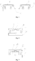
Fig. 1 is a front view of a pedal connecting mechanism provided in an embodiment of the present invention; -
Fig. 2 is a left view of the pedal connecting mechanism provided in the embodiment of the present invention; -
Fig. 3 is a right view of the pedal connecting mechanism provided in the embodiment of the present invention; - Reference numerals: 10. left pedal; 11. first cylindrical shaft; 12. first elastic member; 20. right pedal; 21. second cylindrical shaft; 22. second elastic member; 30. transverse connecting member; 31. first supporting member; and 32. second supporting member.
- The accompanying drawings herein, which are incorporated in the description and constitute a part thereof, illustrate embodiments consistent with the present invention and are used together with the description to explain the principles of the present invention.
- The present invention is further described in detail below by particular embodiments and with reference to the accompanying drawings.
- As shown in
Fig. 1 , a pedal connecting mechanism comprisesleft pedal 10,right pedal 20 and transverse connectingmember 30, wherein a first cylindrical shaft 11 is centrally and transversely provided along the bottom of theleft pedal 10; a first supportingmember 31 is provided on the left side of a top wall of the transverse connectingmember 30, and a first groove matching the first cylindrical shaft 11 is provided on the first supportingmember 31; the first cylindrical shaft 11 is provided inside the first groove so that theleft pedal 10 is rotatably connected to the first supportingmember 31; a secondcylindrical shaft 21 is centrally and transversely provided along the bottom of theright pedal 20; a second supportingmember 32 is provided on the right side of the top wall of the transverse connectingmember 30, and a second groove matching the secondcylindrical shaft 21 is provided on the second supportingmember 32; and the secondcylindrical shaft 21 is provided inside the second groove so that theright pedal 20 is rotatably connected to the second supportingmember 32. - The arrangement of the pedal connecting mechanism will be further described below.
- The first cylindrical shaft 11 is composed of two transversely arranged first cylinders, which are symmetrically provided on two sides of the bottom of the
left pedal 10; two first supportingmembers 31 are correspondingly provided on the left side of the top wall of the transverse connectingmember 30, and a first groove matching the first cylinder is provided on each of the first supportingmembers 31; theleft pedal 10 is rotatably connected to the first supportingmembers 31; the secondcylindrical shaft 21 is composed of two transversely provided second cylinders, which are symmetrically provided on two sides of the bottom of theright pedal 20; two second supportingmembers 32 are correspondingly provided on the right side of the top wall of the transverse connectingmember 30, and a second groove matching the second cylinder is provided on each of the second supportingmembers 32; and theright pedal 20 is rotatably connected to the second supportingmembers 32. - Preferably, the pedal connecting mechanism further comprises a first
elastic member 12 and a secondelastic member 22, wherein one end of the firstelastic member 12 is connected to the bottom of theleft pedal 10, and the other end thereof is correspondingly connected to the left side of the top wall of the transverse connectingmember 30; and one end of the secondelastic member 22 is connected to the bottom of theright pedal 20, and the other end thereof is connected to the right side of the top wall of the transverse connectingmember 30. The firstelastic member 12 and the secondelastic member 22 may be both provided as, but not limited to, springs, and may be provided as other suitable elastic members. The elastic members allow the user to feel cushioned to a certain extent after stepping on the pedals, thereby increasing the comfort. The number of firstelastic members 12 is four, and one end of each of the four firstelastic members 12 is respectively connected to each of the four corners of the bottom of theleft pedal 10 and the other end thereof is respectively connected to the left side of the top wall of the transverse connectingmember 30; and the number of secondelastic members 22 is four, and one end of each of the four secondelastic members 22 is respectively connected to each of the four corners of the bottom of theright pedal 20 and the other end thereof is respectively connected to the right side of the top wall of the transverse connectingmember 30. - Preferably, the transverse connecting
member 30 may be provided as a flat plate, two sides being symmetrically inwardly recessed at a middle part in a longitudinal direction of the flat plate. - In the pedal connecting mechanism provided in the embodiment of the present invention, the transverse connecting
member 30 is provided at the bottoms of theleft pedal 10 and theright pedal 20, theleft pedal 10 and theright pedal 20 are respectively rotatably connected to the transverse connectingmember 30, and theleft pedal 10 and theright pedal 20 are independent of each other; when the balancing scooter is in use, the gravity applied by the human body to the pedals is transmitted to the transverse connectingmember 30, the transverse connectingmember 30 bears the gravity of the human body and is uniformly stressed, avoiding the drawback that an intermediate shaft, which is used to connect the left pedal with the right pedal of the balancing scooter of the prior art and bears the gravity of the human body, is easily worn or even broken. The balancing scooter made by using this pedal connecting mechanism is reliable, safe and durable. Furthermore, the pedal connecting mechanism can be applied not only to a double-wheeled balancing scooter, but also to a three-wheeled balancing scooter, a four-wheeled balancing scooter, a six-wheeled balancing scooter or other suitable types of scooters, and has a wide range of applications, strong practicality, and great business prospects. - The present invention further provides an electric balancing scooter employing the pedal connecting mechanism comprises a housing, the pedal connecting mechanism, wheels, electric motors, sensing systems, at least one signal processor and a power supply, wherein an accommodation cavity is provided in the housing, and a left-right symmetrical fist notch and second notch are provided in a top face of the accommodation cavity; the first notch matches the left pedal 10; the second notch matches the right pedal 20; the pedal connecting mechanism is provided within the accommodation cavity, in which the left pedal 10 is provided within the first notch and the right pedal 20 is provided within the second notch; the wheels comprise a left wheel and a right wheel, which are respectively provided on left and right sides of the housing; the electric motors comprise a first electric motor and a second electric motor; the first electric motor is provided in the left wheel, with a power output end being connected to the left wheel for driving the left wheel; the first electric motor receives a signal transmitted from the signal processor and then controls the state of motion of the left wheel; the second electric motor is provided in the right wheel, with a power output end being connected to the right wheel for driving the right wheel; the second electric motor receives a signal transmitted from the signal processor and then controls the state of motion of the right wheel; the sensing systems comprise a first sensing system which is provided at the bottom of the left pedal 10 and parallel to the left pedal 10, and a second sensing system which is provided at the bottom of the right pedal 20 and parallel to the right pedal 20; the first sensing system comprises a first sensing element and at least one first touch sensing switch; the first sensing element senses the state of motion of the left pedal 10, a signal output end thereof being connected to a signal input end of the signal processor; a signal output end of the first touch sensing switch is connected to a signal input end of the first electric motor; the second sensing system comprises a second sensing element and at least one second touch sensing switch; the second sensing element senses the state of motion of the right pedal 20, a signal output end thereof being connected to a signal input end of the signal processor; a signal output end of the second touch sensing switch is connected to a signal input end of the second electric motor; the at least one data processor is provided within the accommodation cavity, signal input ends of the data processor are connected to the signal output ends of the sensing systems, and a signal output end of the data processor is connected to a signal input end of the electric motor; and the power supply is provided in the accommodation cavity to supply electric power to the electric balancing scooter.
- The arrangements of the sensing systems and the signal processor will be further described below.
- The number of signal processors is one; the first sensing element comprises a first gyroscope and a first acceleration sensor; a signal output end of the first gyroscope is connected to a first signal input end of the signal processor; a signal output end of the first acceleration sensor is connected to a second signal input end of the signal processor; the second sensing element comprises a second gyroscope and a second acceleration sensor; a signal output end of the second gyroscope is connected to a third input end of the signal processor; and a signal output end of the second acceleration sensor is connected to a fourth input end of the signal processor.
- Alternatively, the number of signal processors is two, which are denoted as a first signal processor and a second signal processor, respectively; the first sensing element comprises a first gyroscope and a first acceleration sensor; a signal output end of the first gyroscope is connected to a first signal input end of the first signal processor; a signal output end of the first acceleration sensor is connected to a second signal input end of the first signal processor; the second sensing element comprises a second gyroscope and a second acceleration sensor; a signal output end of the second gyroscope is connected to a first input end of the second signal processor; and a signal output end of the second acceleration sensor is connected to a second input end of the second signal processor.
- Furthermore, the number of first touch sensing switches may be two; the number of second touch sensing switches may be two; one of the first sensing switches and one of the second touch sensing switches are standby switches; therefore, standby switches are provided, which is convenient and practical, avoiding the drawback that if only one switch is provided, the balancing scooter cannot start when the switch is broken.
- The operating principle of the electric balancing scooter provided in the present invention is as follows:
- During the operation of the electric balancing scooter, when the user's left foot steps on the
left pedal 10, the first touch sensing switch is turned on, and when the right foot steps on theright pedal 20, the second touch sensing switch is turned on. The user's left foot stepping on theleft pedal 10 tilts theleft pedal 10 forward or backward, and at the same time, the first sensing system, which is connected to the bottom of theleft pedal 10 in parallel, is tilted forward or backward along with theleft pedal 10; in this case, the first sensing element detects the state of motion of theleft pedal 10 at any time and transmits the signal to the signal processor which feeds the signal back to the first electric motor, and the state of motion of the left wheel is adjusted according to the power output from the first electric motor; and on the other hand, the user's right foot stepping on theright pedal 20 tilts theright pedal 20 forward or backward, and at the same time, the second sensing system, which is connected to the bottom of theright pedal 20 in parallel, is tilted forward or backward along with theright pedal 20; in this case, the second sensing element detects the state of motion of theright pedal 20 and transmits the signal to the signal processor which feeds the signal back to the second electric motor, and the state of motion of the right wheel is adjusted according to the power output from the second electric motor. When the user simultaneously presses theleft pedal 10 and theright pedal 20 forward deeply, the left and right wheels are kept rolling forward, and the balancing scooter moves forward; when the user simultaneously presses theleft pedal 10 and theright pedal 20 backward deeply, the left and right wheels roll backward, and the balancing scooter moves backward; and the balancing scooter turns when the user's pressing actions cause the state of motions of theleft pedal 10 and theright pedal 20 to be different. At the same time, the first sensing element and the second sensing element feed back the amplitude of swing of the user's body, causing the first electric motor and the second electric motor to obtain different power outputs, thereby adjusting the speed of the balancing scooter. - For a person skilled in the art, a variety of other corresponding modifications and variations can be made according to the above-described technical solutions and concepts, and all the modifications and variations shall fall within the scope of protection of the claims of the present invention.
Claims (10)
- A pedal connecting mechanism, characterized by comprising a left pedal, a right pedal and a transverse connecting member,
wherein a first cylindrical shaft is provided along the bottom of the left pedal; a first supporting member is provided on the left side of a top wall of the transverse connecting member, and a first groove matching the first cylindrical shaft is provided on the first supporting member; the first cylindrical shaft is provided inside the first groove so that the left pedal is rotatably connected to the first supporting member;
a second cylindrical shaft is provided along the bottom of the right pedal; a second supporting member is provided on the right side of the top wall of the transverse connecting member, and a second groove matching the second cylindrical shaft is provided on the second supporting member; and the second cylindrical shaft is provided inside the second groove so that the right pedal is rotatably connected to the second supporting member. - The pedal connecting mechanism according to claim 1, characterized in that the first cylindrical shaft is composed of two transversely arranged first cylinders, which are symmetrically provided on two sides of the bottom of the left pedal; two first supporting members are correspondingly provided on the left side of the top wall of the transverse connecting member, and a first groove matching the first cylinder is provided on each of the first supporting members; the left pedal is rotatably connected to the first supporting members;
the second cylindrical shaft is composed of two transversely arranged second cylinders, which are symmetrically provided on two sides of the bottom of the right pedal; two second supporting members are correspondingly provided on the right side of the top wall of the transverse connecting member, and a second groove matching the second cylinder is provided on each of the second supporting members; and the right pedal is rotatably connected to the second supporting members. - The pedal connecting mechanism according to claim 1, characterized by further comprising a first elastic member and a second elastic member, wherein one end of the first elastic member is connected to the bottom of the left pedal, and the other end thereof is correspondingly connected to the left side of the top wall of the transverse connecting member; and one end of the second elastic member is connected to the bottom of the right pedal, and the other end thereof is connected to the right side of the top wall of the transverse connecting member.
- The pedal connecting mechanism according to claim 3, characterized in that the first elastic member and the second elastic member are both springs.
- The pedal connecting mechanism according to claim 3, characterized in that the number of the first elastic members is four, and one end of each of the four first elastic members is respectively connected to each of the four corners of the bottom of the left pedal and the other end thereof is respectively connected to the left side of the top wall of the transverse connecting member; and
the number of the second elastic members is four, and one end of each of the four second elastic members is respectively connected to each of the four corners of the bottom of the right pedal and the other end thereof is respectively connected to the right side of the top wall of the transverse connecting member. - The pedal connecting mechanism according to claim 1, characterized in that the transverse connecting member is a flat plate, with two sides being symmetrically inwardly recessed at a middle part in a longitudinal direction of the flat plate.
- An electric balancing scooter employing the pedal connecting mechanism according to any one of claims 1-6, characterized by comprising a housing, the pedal connecting mechanism, wheels, electric motors, sensing systems, at least one signal processor and a power supply,
wherein an accommodation cavity is provided in the housing, and a left-right symmetrical fist notch and second notch are provided in a top face of the accommodation cavity; the first notch matches the left pedal; the second notch matches the right pedal;
the pedal connecting mechanism is provided within the accommodation cavity, in which the left pedal is provided within the first notch and the right pedal is provided within the second notch;
the wheels comprise a left wheel and a right wheel, which are respectively provided on left and right sides of the housing;
the electric motors comprise a first electric motor and a second electric motor; the first electric motor is provided in the left wheel, with a power output end being connected to the left wheel for driving the left wheel; the first electric motor receives a signal transmitted from the signal processor and then controls the state of motion of the left wheel; the second electric motor is provided in the right wheel, with a power output end being connected to the right wheel for driving the right wheel; the second electric motor receives a signal transmitted from the signal processor and then controls the state of motion of the right wheel;
the sensing systems comprise a first sensing system which is provided at the bottom of the left pedal and parallel to the left pedal, and a second sensing system which is provided at the bottom of the right pedal and parallel to the right pedal; the first sensing system comprises a first sensing element and at least one first touch sensing switch; the first sensing element senses the state of motion of the left pedal, a signal output end of the first sensing element being connected to a signal input end of the signal processor; a signal output end of the first touch sensing switch is connected to a signal input end of the first electric motor;
the second sensing system comprises a second sensing element and at least one second touch sensing switch; the second sensing element senses the state of motion of the right pedal, a signal output end of the second sensing element being connected to a signal input end of the signal processor; a signal output end of the second touch sensing switch is connected to a signal input end of the second electric motor;
the at least one data processor is provided within the accommodation cavity, signal input ends of the data processor are connected to the signal output ends of the sensing systems, and a signal output end of the data processor is connected to a signal input end of the electric motor; and
the power supply is provided in the accommodation cavity to supply electric power to the electric balancing scooter. - The electric balancing scooter employing the pedal connecting mechanism according to claim 7, characterized in that the number of the signal processors is one;
the first sensing element comprises a first gyroscope and a first acceleration sensor; a signal output end of the first gyroscope is connected to a first signal input end of the signal processor; a signal output end of the first acceleration sensor is connected to a second signal input end of the signal processor;
the second sensing element comprises a second gyroscope and a second acceleration sensor; a signal output end of the second gyroscope is connected to a third input end of the signal processor; and a signal output end of the second acceleration sensor is connected to a fourth input end of the signal processor. - The electric balancing scooter employing the pedal connecting mechanism according to claim 7, characterized in that the number of the signal processors is two, which are denoted as a first signal processor and a second signal processor, respectively;
the first sensing element comprises a first gyroscope and a first acceleration sensor; a signal output end of the first gyroscope is connected to a first signal input end of the first signal processor; a signal output end of the first acceleration sensor is connected to a second signal input end of the first signal processor;
the second sensing element comprises a second gyroscope and a second acceleration sensor; a signal output end of the second gyroscope is connected to a first input end of the second signal processor; and a signal output end of the second acceleration sensor is connected to a second input end of the second signal processor. - The electric balancing scooter employing the pedal connecting mechanism according to claim 7, characterized in that the number of the first touch sensing switches is two, and the number of the second touch sensing switches is two.
Applications Claiming Priority (2)
| Application Number | Priority Date | Filing Date | Title |
|---|---|---|---|
| CN201610077468.XA CN105730574B (en) | 2016-02-03 | 2016-02-03 | Pedal bindiny mechanism and the electrodynamic balance vehicle for using the pedal bindiny mechanism |
| PCT/CN2016/089394 WO2017133184A1 (en) | 2016-02-03 | 2016-07-08 | Pedal-connecting mechanism and electric self-balancing scooter adopting same |
Publications (2)
| Publication Number | Publication Date |
|---|---|
| EP3441293A1 true EP3441293A1 (en) | 2019-02-13 |
| EP3441293A4 EP3441293A4 (en) | 2020-01-22 |
Family
ID=56244926
Family Applications (1)
| Application Number | Title | Priority Date | Filing Date |
|---|---|---|---|
| EP16889002.8A Pending EP3441293A4 (en) | 2016-02-03 | 2016-07-08 | PEDAL CONNECTION MECHANISM AND ELECTRICAL HOVERBOARD THEREFOR |
Country Status (4)
| Country | Link |
|---|---|
| US (2) | US20170217532A1 (en) |
| EP (1) | EP3441293A4 (en) |
| CN (1) | CN105730574B (en) |
| WO (1) | WO2017133184A1 (en) |
Cited By (1)
| Publication number | Priority date | Publication date | Assignee | Title |
|---|---|---|---|---|
| EP3441293A4 (en) * | 2016-02-03 | 2020-01-22 | Zhejiang Raymond Way Electronic Technology Co., Ltd | PEDAL CONNECTION MECHANISM AND ELECTRICAL HOVERBOARD THEREFOR |
Families Citing this family (14)
| Publication number | Priority date | Publication date | Assignee | Title |
|---|---|---|---|---|
| CN106275170B (en) * | 2016-08-29 | 2018-11-13 | 深圳市动平衡科技有限公司 | Posture vehicle |
| CN206125273U (en) * | 2016-09-08 | 2017-04-26 | 深圳乐行天下科技有限公司 | Balance car |
| EP3592636B1 (en) * | 2017-03-09 | 2022-04-06 | Shane Chen | Auto-balancing vehicle with independent wheel control |
| CN106892039B (en) * | 2017-03-09 | 2022-08-16 | 深圳市亮点智控科技有限公司 | Self-balancing device and electric vehicle |
| CN106890446B (en) * | 2017-03-22 | 2023-04-07 | 深圳市高斯拓普科技有限公司 | Scooter |
| CN106904232A (en) * | 2017-03-22 | 2017-06-30 | 深圳市高斯拓普科技有限公司 | The governor motion and balance car of a kind of balance car |
| CN107097881A (en) * | 2017-04-28 | 2017-08-29 | 深圳市亮点智控科技有限公司 | A kind of control method of posture car and posture car |
| CN108045473B (en) * | 2017-11-30 | 2019-07-09 | 重庆徐丁科技有限公司 | A kind of damping type motorcycle foot pedal |
| CN109094702B (en) * | 2018-08-26 | 2020-10-23 | 深圳市领航致远科技有限公司 | Pedal assembly of balance car and balance car |
| CN212709804U (en) * | 2020-06-19 | 2021-03-16 | 浙江阿尔郎科技有限公司 | Upper shell assembly and balance car thereof |
| CN112960053B (en) * | 2021-04-12 | 2024-12-13 | 浙江普瑞圣工贸有限公司 | A balancing vehicle with swing pedals |
| CN114771712B (en) * | 2021-07-20 | 2024-06-18 | 苏州昊维工业产品设计有限公司 | Vehicle pedal assembly and electric vehicle |
| CN114954767A (en) * | 2021-07-20 | 2022-08-30 | 苏州昊维工业产品设计有限公司 | Foot pedal for stepless control of children's car, control method and application |
| CN113753164A (en) * | 2021-09-07 | 2021-12-07 | 深圳市亮点智控科技有限公司 | Motion sensing vehicle operation control system and method |
Family Cites Families (34)
| Publication number | Priority date | Publication date | Assignee | Title |
|---|---|---|---|---|
| JPS4855953U (en) * | 1971-10-25 | 1973-07-18 | ||
| US6572514B1 (en) * | 1998-12-09 | 2003-06-03 | Kathleen E. Calafato | Exerciser with counter-reciprocating pedals |
| US6761666B2 (en) * | 2002-09-06 | 2004-07-13 | Energy Star Co., Ltd. | Reciprocal device having sensing feature |
| US6899657B2 (en) * | 2002-11-19 | 2005-05-31 | Jin Chen Chuang | Exerciser for stepping and swinging exercises |
| US6921353B2 (en) * | 2003-01-17 | 2005-07-26 | Jin Chen Chuang | Stepping exerciser having rotatable foot pedals |
| DE102005059361A1 (en) * | 2005-02-25 | 2006-08-31 | Ulrich Kahlert | Two-wheeled battery-powered vehicle for one person |
| JP4650327B2 (en) * | 2005-04-14 | 2011-03-16 | トヨタ自動車株式会社 | Coaxial motorcycle |
| US7497811B2 (en) * | 2006-05-31 | 2009-03-03 | Barua Arun Kumar | Pedal exercising device |
| JP4240114B2 (en) * | 2006-11-15 | 2009-03-18 | トヨタ自動車株式会社 | Traveling device |
| TWM367013U (en) * | 2009-03-26 | 2009-10-21 | Luo wei ci | Twisting and jumping type sports apparatus |
| US7771327B1 (en) * | 2009-04-02 | 2010-08-10 | Terry Reams | Exercise device with footboards having tubular support |
| JP2012126224A (en) * | 2010-12-15 | 2012-07-05 | Bosch Corp | Inverted pendulum type moving body |
| US9156516B2 (en) * | 2011-04-05 | 2015-10-13 | Ulrich Kahlert | Two-wheeled battery-powered vehicle |
| US8738278B2 (en) * | 2012-02-12 | 2014-05-27 | Shane Chen | Two-wheel, self-balancing vehicle with independently movable foot placement sections |
| US9039583B2 (en) * | 2013-03-18 | 2015-05-26 | Chin-Chen Huang | Foot exercise machine |
| CN103600799B (en) * | 2013-10-17 | 2015-12-23 | 上海交通大学 | Based on steering control system and the balanced car with two wheels thereof of pressure sensor |
| CN105216933B (en) * | 2014-06-10 | 2019-04-16 | 扬顶(天津)商贸有限公司 | A kind of frame assembly of double-wheel self-balancing electrombile |
| CN104014123A (en) * | 2014-06-13 | 2014-09-03 | 杭州骑客智能科技有限公司 | Longitudinal double-wheel vehicle body |
| TWI542383B (en) * | 2014-08-27 | 2016-07-21 | 岱宇國際股份有限公司 | Figure trimmer |
| CN204223088U (en) * | 2014-09-26 | 2015-03-25 | 杭州云造科技有限公司 | A self-balancing scooter |
| CN204323596U (en) * | 2014-11-24 | 2015-05-13 | 深圳市凯旸电机有限公司 | A kind of bindiny mechanism of balance truck foot platform |
| CN104608871B (en) * | 2015-02-05 | 2018-06-26 | 深圳市凯旸电机有限公司 | A kind of balance car pedal control mechanism and its balance car |
| CN204956786U (en) * | 2015-07-31 | 2016-01-13 | 青岛行者智能科技有限公司 | Double -wheel balancing cart |
| CN105270526B (en) * | 2015-09-30 | 2018-01-16 | 江西迪安新能源动力有限公司 | A kind of two-wheel electric balance car |
| CN106564546B (en) * | 2015-10-10 | 2020-08-14 | 杭州骑客智能科技有限公司 | Full-posture electrodynamic balance swing car |
| CN106627895B (en) * | 2016-11-25 | 2020-01-07 | 杭州骑客智能科技有限公司 | A human-machine interactive somatosensory vehicle and its control method and device |
| CN105416467A (en) * | 2015-12-14 | 2016-03-23 | 卢南方 | Self-balance double-wheel electric scooter |
| US9403573B1 (en) * | 2015-12-29 | 2016-08-02 | Angelo L. Mazzei | Hover board tricycle |
| CN105416469A (en) * | 2016-01-07 | 2016-03-23 | 浙江同硕科技有限公司 | Electric scooter |
| CN105730574B (en) * | 2016-02-03 | 2018-08-17 | 浙江瑞萌威电子科技有限公司 | Pedal bindiny mechanism and the electrodynamic balance vehicle for using the pedal bindiny mechanism |
| CN205345191U (en) * | 2016-02-03 | 2016-06-29 | 深圳市高斯拓普科技有限公司 | Footboard coupling mechanism and adopt this footboard coupling mechanism's electrodynamic balance car |
| EP3299267B1 (en) * | 2016-08-08 | 2021-08-25 | Hangzhou Chic Intelligent Technology Co., Ltd | Human-machine interaction motion apparatus |
| US10144477B2 (en) * | 2016-11-09 | 2018-12-04 | Zake Ip Holdings, Llc | Gear drive two-wheel scooter |
| KR101724327B1 (en) * | 2017-01-05 | 2017-04-07 | 이상곤 | Kinetic chain Energy Movement board for posture of pilates reformer |
-
2016
- 2016-02-03 CN CN201610077468.XA patent/CN105730574B/en not_active Expired - Fee Related
- 2016-07-08 WO PCT/CN2016/089394 patent/WO2017133184A1/en not_active Ceased
- 2016-07-08 EP EP16889002.8A patent/EP3441293A4/en active Pending
- 2016-12-13 US US15/376,683 patent/US20170217532A1/en not_active Abandoned
-
2017
- 2017-01-25 US US15/414,663 patent/US10286974B2/en not_active Expired - Fee Related
Cited By (1)
| Publication number | Priority date | Publication date | Assignee | Title |
|---|---|---|---|---|
| EP3441293A4 (en) * | 2016-02-03 | 2020-01-22 | Zhejiang Raymond Way Electronic Technology Co., Ltd | PEDAL CONNECTION MECHANISM AND ELECTRICAL HOVERBOARD THEREFOR |
Also Published As
| Publication number | Publication date |
|---|---|
| WO2017133184A1 (en) | 2017-08-10 |
| CN105730574B (en) | 2018-08-17 |
| CN105730574A (en) | 2016-07-06 |
| EP3441293A4 (en) | 2020-01-22 |
| US10286974B2 (en) | 2019-05-14 |
| US20170217530A1 (en) | 2017-08-03 |
| US20170217532A1 (en) | 2017-08-03 |
Similar Documents
| Publication | Publication Date | Title |
|---|---|---|
| US10286974B2 (en) | Pedal connecting mechanism and electric balance scooter employing same | |
| US20170217524A1 (en) | Pedal connection mechanism and electric balancing vehicle using the same | |
| US20180148120A1 (en) | Balancing vehicle | |
| CN206187204U (en) | Car is felt to man -machine interactive body | |
| JP6250824B2 (en) | Separate electric skateboard | |
| KR101800679B1 (en) | The handsfree balancing scooter with a steering mechanism of twist type using feet | |
| EP2872383B1 (en) | Foot-propelled wheeled hobby and/or sport device | |
| CN104494750B (en) | A self-balancing two-wheeled vehicle | |
| CN213347728U (en) | a skateboard | |
| JP6663847B2 (en) | A vehicle for the movement of a pilot equipped with a ball rolling in an arbitrary direction on the ground surface | |
| JP2010030568A (en) | Vehicle body structure and coaxial two-wheel vehicle | |
| CN105346651B (en) | Electric balance car | |
| CN106394760A (en) | Foot-controlled balance vehicle | |
| CN105416484B (en) | electric balance car | |
| CN105416485B (en) | Electric balance car | |
| CN105501357A (en) | Self-balancing electric scooter | |
| CN108657343B (en) | Self-balancing electric drift shoes | |
| KR102344052B1 (en) | Moving device available with electric kick board and electric wheel | |
| CN205554476U (en) | Take pressure perception electrodynamic balance car of handrail | |
| CN215679302U (en) | VR motion control device | |
| CN203469429U (en) | Split type electric skateboard | |
| KR200471943Y1 (en) | Saddle for bicycle | |
| CN205469529U (en) | Self -balancing electric scooter | |
| US20200354007A1 (en) | Novel electric double-wheel balance car | |
| CN109987184A (en) | Scooter |
Legal Events
| Date | Code | Title | Description |
|---|---|---|---|
| STAA | Information on the status of an ep patent application or granted ep patent |
Free format text: STATUS: THE INTERNATIONAL PUBLICATION HAS BEEN MADE |
|
| PUAI | Public reference made under article 153(3) epc to a published international application that has entered the european phase |
Free format text: ORIGINAL CODE: 0009012 |
|
| STAA | Information on the status of an ep patent application or granted ep patent |
Free format text: STATUS: REQUEST FOR EXAMINATION WAS MADE |
|
| 17P | Request for examination filed |
Effective date: 20181207 |
|
| AK | Designated contracting states |
Kind code of ref document: A1 Designated state(s): AL AT BE BG CH CY CZ DE DK EE ES FI FR GB GR HR HU IE IS IT LI LT LU LV MC MK MT NL NO PL PT RO RS SE SI SK SM TR |
|
| AX | Request for extension of the european patent |
Extension state: BA ME |
|
| DAV | Request for validation of the european patent (deleted) | ||
| DAX | Request for extension of the european patent (deleted) | ||
| A4 | Supplementary search report drawn up and despatched |
Effective date: 20200102 |
|
| RIC1 | Information provided on ipc code assigned before grant |
Ipc: B62J 25/00 20060101ALI20191217BHEP Ipc: B62K 23/08 20060101ALI20191217BHEP Ipc: B62K 11/00 20060101AFI20191217BHEP |
|
| STAA | Information on the status of an ep patent application or granted ep patent |
Free format text: STATUS: EXAMINATION IS IN PROGRESS |
|
| RIC1 | Information provided on ipc code assigned before grant |
Ipc: B62K 23/08 20060101ALI20211220BHEP Ipc: B62J 25/00 20200101ALI20211220BHEP Ipc: B62K 11/00 20060101AFI20211220BHEP |
|
| 17Q | First examination report despatched |
Effective date: 20220125 |