EP3441274A1 - Traveling control device, vehicle, and traveling control method - Google Patents
Traveling control device, vehicle, and traveling control method Download PDFInfo
- Publication number
- EP3441274A1 EP3441274A1 EP18187332.4A EP18187332A EP3441274A1 EP 3441274 A1 EP3441274 A1 EP 3441274A1 EP 18187332 A EP18187332 A EP 18187332A EP 3441274 A1 EP3441274 A1 EP 3441274A1
- Authority
- EP
- European Patent Office
- Prior art keywords
- traveling
- vehicle
- driven
- inertia
- traveling control
- Prior art date
- Legal status (The legal status is an assumption and is not a legal conclusion. Google has not performed a legal analysis and makes no representation as to the accuracy of the status listed.)
- Withdrawn
Links
Images


Classifications
-
- B—PERFORMING OPERATIONS; TRANSPORTING
- B60—VEHICLES IN GENERAL
- B60W—CONJOINT CONTROL OF VEHICLE SUB-UNITS OF DIFFERENT TYPE OR DIFFERENT FUNCTION; CONTROL SYSTEMS SPECIALLY ADAPTED FOR HYBRID VEHICLES; ROAD VEHICLE DRIVE CONTROL SYSTEMS FOR PURPOSES NOT RELATED TO THE CONTROL OF A PARTICULAR SUB-UNIT
- B60W30/00—Purposes of road vehicle drive control systems not related to the control of a particular sub-unit, e.g. of systems using conjoint control of vehicle sub-units
- B60W30/14—Adaptive cruise control
-
- B—PERFORMING OPERATIONS; TRANSPORTING
- B60—VEHICLES IN GENERAL
- B60W—CONJOINT CONTROL OF VEHICLE SUB-UNITS OF DIFFERENT TYPE OR DIFFERENT FUNCTION; CONTROL SYSTEMS SPECIALLY ADAPTED FOR HYBRID VEHICLES; ROAD VEHICLE DRIVE CONTROL SYSTEMS FOR PURPOSES NOT RELATED TO THE CONTROL OF A PARTICULAR SUB-UNIT
- B60W30/00—Purposes of road vehicle drive control systems not related to the control of a particular sub-unit, e.g. of systems using conjoint control of vehicle sub-units
- B60W30/18—Propelling the vehicle
- B60W30/18009—Propelling the vehicle related to particular drive situations
- B60W30/18072—Coasting
-
- B—PERFORMING OPERATIONS; TRANSPORTING
- B60—VEHICLES IN GENERAL
- B60W—CONJOINT CONTROL OF VEHICLE SUB-UNITS OF DIFFERENT TYPE OR DIFFERENT FUNCTION; CONTROL SYSTEMS SPECIALLY ADAPTED FOR HYBRID VEHICLES; ROAD VEHICLE DRIVE CONTROL SYSTEMS FOR PURPOSES NOT RELATED TO THE CONTROL OF A PARTICULAR SUB-UNIT
- B60W30/00—Purposes of road vehicle drive control systems not related to the control of a particular sub-unit, e.g. of systems using conjoint control of vehicle sub-units
- B60W30/14—Adaptive cruise control
- B60W30/16—Control of distance between vehicles, e.g. keeping a distance to preceding vehicle
-
- B—PERFORMING OPERATIONS; TRANSPORTING
- B60—VEHICLES IN GENERAL
- B60K—ARRANGEMENT OR MOUNTING OF PROPULSION UNITS OR OF TRANSMISSIONS IN VEHICLES; ARRANGEMENT OR MOUNTING OF PLURAL DIVERSE PRIME-MOVERS IN VEHICLES; AUXILIARY DRIVES FOR VEHICLES; INSTRUMENTATION OR DASHBOARDS FOR VEHICLES; ARRANGEMENTS IN CONNECTION WITH COOLING, AIR INTAKE, GAS EXHAUST OR FUEL SUPPLY OF PROPULSION UNITS IN VEHICLES
- B60K31/00—Vehicle fittings, acting on a single sub-unit only, for automatically controlling vehicle speed, i.e. preventing speed from exceeding an arbitrarily established velocity or maintaining speed at a particular velocity, as selected by the vehicle operator
-
- B—PERFORMING OPERATIONS; TRANSPORTING
- B60—VEHICLES IN GENERAL
- B60W—CONJOINT CONTROL OF VEHICLE SUB-UNITS OF DIFFERENT TYPE OR DIFFERENT FUNCTION; CONTROL SYSTEMS SPECIALLY ADAPTED FOR HYBRID VEHICLES; ROAD VEHICLE DRIVE CONTROL SYSTEMS FOR PURPOSES NOT RELATED TO THE CONTROL OF A PARTICULAR SUB-UNIT
- B60W2520/00—Input parameters relating to overall vehicle dynamics
- B60W2520/10—Longitudinal speed
-
- B—PERFORMING OPERATIONS; TRANSPORTING
- B60—VEHICLES IN GENERAL
- B60W—CONJOINT CONTROL OF VEHICLE SUB-UNITS OF DIFFERENT TYPE OR DIFFERENT FUNCTION; CONTROL SYSTEMS SPECIALLY ADAPTED FOR HYBRID VEHICLES; ROAD VEHICLE DRIVE CONTROL SYSTEMS FOR PURPOSES NOT RELATED TO THE CONTROL OF A PARTICULAR SUB-UNIT
- B60W2540/00—Input parameters relating to occupants
- B60W2540/10—Accelerator pedal position
-
- B—PERFORMING OPERATIONS; TRANSPORTING
- B60—VEHICLES IN GENERAL
- B60W—CONJOINT CONTROL OF VEHICLE SUB-UNITS OF DIFFERENT TYPE OR DIFFERENT FUNCTION; CONTROL SYSTEMS SPECIALLY ADAPTED FOR HYBRID VEHICLES; ROAD VEHICLE DRIVE CONTROL SYSTEMS FOR PURPOSES NOT RELATED TO THE CONTROL OF A PARTICULAR SUB-UNIT
- B60W2540/00—Input parameters relating to occupants
- B60W2540/12—Brake pedal position
-
- B—PERFORMING OPERATIONS; TRANSPORTING
- B60—VEHICLES IN GENERAL
- B60W—CONJOINT CONTROL OF VEHICLE SUB-UNITS OF DIFFERENT TYPE OR DIFFERENT FUNCTION; CONTROL SYSTEMS SPECIALLY ADAPTED FOR HYBRID VEHICLES; ROAD VEHICLE DRIVE CONTROL SYSTEMS FOR PURPOSES NOT RELATED TO THE CONTROL OF A PARTICULAR SUB-UNIT
- B60W2554/00—Input parameters relating to objects
- B60W2554/80—Spatial relation or speed relative to objects
- B60W2554/801—Lateral distance
-
- B—PERFORMING OPERATIONS; TRANSPORTING
- B60—VEHICLES IN GENERAL
- B60W—CONJOINT CONTROL OF VEHICLE SUB-UNITS OF DIFFERENT TYPE OR DIFFERENT FUNCTION; CONTROL SYSTEMS SPECIALLY ADAPTED FOR HYBRID VEHICLES; ROAD VEHICLE DRIVE CONTROL SYSTEMS FOR PURPOSES NOT RELATED TO THE CONTROL OF A PARTICULAR SUB-UNIT
- B60W2554/00—Input parameters relating to objects
- B60W2554/80—Spatial relation or speed relative to objects
- B60W2554/802—Longitudinal distance
-
- B—PERFORMING OPERATIONS; TRANSPORTING
- B60—VEHICLES IN GENERAL
- B60W—CONJOINT CONTROL OF VEHICLE SUB-UNITS OF DIFFERENT TYPE OR DIFFERENT FUNCTION; CONTROL SYSTEMS SPECIALLY ADAPTED FOR HYBRID VEHICLES; ROAD VEHICLE DRIVE CONTROL SYSTEMS FOR PURPOSES NOT RELATED TO THE CONTROL OF A PARTICULAR SUB-UNIT
- B60W2555/00—Input parameters relating to exterior conditions, not covered by groups B60W2552/00, B60W2554/00
- B60W2555/60—Traffic rules, e.g. speed limits or right of way
-
- Y—GENERAL TAGGING OF NEW TECHNOLOGICAL DEVELOPMENTS; GENERAL TAGGING OF CROSS-SECTIONAL TECHNOLOGIES SPANNING OVER SEVERAL SECTIONS OF THE IPC; TECHNICAL SUBJECTS COVERED BY FORMER USPC CROSS-REFERENCE ART COLLECTIONS [XRACs] AND DIGESTS
- Y02—TECHNOLOGIES OR APPLICATIONS FOR MITIGATION OR ADAPTATION AGAINST CLIMATE CHANGE
- Y02T—CLIMATE CHANGE MITIGATION TECHNOLOGIES RELATED TO TRANSPORTATION
- Y02T10/00—Road transport of goods or passengers
- Y02T10/60—Other road transportation technologies with climate change mitigation effect
Definitions
- the present disclosure relates to a traveling control device, a vehicle, and a traveling control method.
- the driven traveling includes the Adaptive Cruise Control (ACC) that allows a vehicle to travel at a constant speed while following a preceding vehicle with a constant distance being kept between these vehicles.
- ACC Adaptive Cruise Control
- the driven traveling when a relative speed of the vehicle to the preceding vehicle is greater than or equal to a predetermined speed, the necessity of stopping the vehicle is high.
- the necessity of stopping the vehicle is also high when a traffic light in the vehicle-traveling direction is red.
- the vehicle In a case where the necessity of stopping the vehicle in driven traveling is high, the vehicle is decelerated by controlling the driven traveling for greater safety.
- An object of the present disclosure is to provide a traveling control device, vehicle, and traveling control method which make it possible to reduce wasteful energy consumption.
- a traveling control device includes: a traveling-condition determining section configured to determine whether or not necessity of decelerating a vehicle is high, based on a traveling condition; and a traveling control section configured to switch traveling of the vehicle from driven traveling to inertia traveling, when the traveling of the vehicle is the driven traveling and when the traveling-condition determining section determines that the necessity of stopping the vehicle is high.
- a vehicle according to the present disclosure includes the aforementioned traveling control device.
- a traveling control method includes: determining whether or not necessity of stopping a vehicle is high, based on a traveling condition; and switching traveling of the vehicle from driven traveling to inertia traveling, when the traveling of the vehicle is the driven traveling and when it is determined that the necessity of stopping the vehicle is high.
- wasteful energy consumption can be reduced.
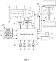
- FIG. 1 is a block diagram illustrating an exemplary configuration of the vehicle including traveling control device 100 according to the embodiment of the present disclosure. Note here that, the illustration and description are given with focuses on parts relevant to traveling control device 100.
- Vehicle 1 illustrated in FIG. 1 is, for example, a large vehicle such as a truck, in which a straight-six diesel engine is mounted.
- vehicle 1 includes engine 3, clutch 4, gearbox (transmission) 5, thrust shaft (propeller shaft) 6, differential device (differential gear) 7, driving shaft (drive shaft) 8, and wheels 9, as components of a driving system allowing the vehicle to travel.
- the power of engine 3 is transmitted to gearbox 5 via clutch 4, and the power transmitted to gearbox 5 is further transmitted to wheels 9 via thrust shaft 6, differential device 7, and driving shaft 8. In this way, the power of engine 3 is transmitted to wheels 9, so that vehicle 1 travels.
- Vehicle 1 also includes braking device 40 as a component of a braking system for stopping the vehicle.
- Braking device 40 includes footbrakes 41 for applying the resistance to wheels 9, retarder 42 for applying the resistance to thrust shaft 6, and auxiliary brake 43, such as an exhaust brake for applying a load to engine 3.
- Vehicle 1 further includes automatic traveling device 2 as a component of a control system for controlling the traveling of vehicle 1.
- Automatic traveling device 2 is a device allowing vehicle 1 to automatically travel, by controlling the output of engine 3, connection or disconnection of clutch 4, and gear shift of gearbox 5, and automatic traveling device 2 includes multiple control units.
- automatic traveling device 2 includes engine ECU (engine control unit) 10, power-transmitting ECU (power-transmitting control unit) 11, target-vehicle-speed setting unit 13, increase-value/decrease-value setting unit 14, traveling-condition obtaining unit 20, vehicle-information obtaining unit 30, and traveling control device 100.
- engine ECU 10, power-transmitting ECU 11, and traveling control device 100 are connected to one another by an in-vehicle network, so that they can transmit and receive required data and control signals to and from one another.
- Engine ECU 10 controls the output of engine 3.
- Power-transmitting ECU 11 controls the connection or disconnection of clutch 4 and the gear shift of gearbox 5.
- Target-vehicle-speed setting unit 13 sets, in traveling control device 100, the target speed of vehicle 1 during driven traveling.
- Increase-value/decrease-value setting unit 14 sets, in traveling control device 100, a speed decrease value and a speed increase value of vehicle 1 during driven traveling.
- the target speed, speed decrease value, and speed increase value are parameters used for the automatic traveling of vehicle 1.
- Target-vehicle-speed setting unit 13 and increase-value/decrease-value setting unit 14 include an information input interface, such as a display having a touch panel and being disposed, for example, to the dashboard (not illustrated) of a driver's seat, and target-vehicle-speed setting unit 13 and increase-value/decrease-value setting unit 14 receive setting of the aforementioned parameters input by a driver.
- the target speed, speed decrease value, and speed increase value may appropriately be referred to as "setting information.”
- Traveling-condition obtaining unit 20 obtains the traveling condition indicating the road conditions and the current position of vehicle 1, and outputs them to traveling control device 100.
- traveling-condition obtaining unit 20 includes current-position obtaining unit 21 that is a receiver of the Global Positioning System (GPS), weather obtaining unit 22 that obtains the weather during traveling, and surroundings sensor 23 that detects distances and/or vehicle-speed differences between vehicle 1 and surrounding vehicles (e.g., a preceding vehicle, parallel traveling vehicle and/or the like).
- GPS Global Positioning System
- weather obtaining unit 22 that obtains the weather during traveling
- surroundings sensor 23 that detects distances and/or vehicle-speed differences between vehicle 1 and surrounding vehicles (e.g., a preceding vehicle, parallel traveling vehicle and/or the like).
- Vehicle-information obtaining unit 30 obtains vehicle information indicating driver-handling information and/or the state of vehicle 1, and outputs the vehicle information to traveling control device 100.
- vehicle-information obtaining unit 30 includes accelerator sensor 31 that detects the depressed amount of an accelerator pedal, brake switch 32 that detects whether or not a brake pedal is stepped on, shift lever 33, turn signal switch 34, and vehicle-speed sensor 35 that detects the speed of vehicle 1.
- Traveling control device 100 generates a traveling schedule including the driven traveling (autocruise traveling) and inertia traveling, based on the aforementioned setting information, traveling condition, and vehicle information. Then, traveling control device 100 controls each part of vehicle 1 so that vehicle 1 travels in accordance with the generated traveling schedule.
- the inertia traveling includes engine-braking traveling and neutral inertia traveling (which may, hereinafter, also be referred to as "N coasting").
- engine-braking traveling a vehicle travels in which the continuity of the power transmission path between engine 3 and wheels 9 is left and engine braking thus comes into effect by the retarding forces of engine 3.
- neutral inertia traveling the vehicle travels in which the power transmission path between engine 3 and wheels 9 is cut off.
- fuel injections in engine 3 are suspended during the engine-braking traveling and N coasting.
- a throttle valve (not illustrated) is controlled such that the degree of opening of the throttle valve corresponding to the fuel injection quantity is the lowest.
- the inertial traveling is to denote the engine-braking traveling.
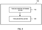
- FIG. 2 is a block diagram illustrating an example of the configuration of traveling control device 100.
- traveling control device 100 includes traveling-condition determining section 110 and traveling control section 120.
- Traveling-condition determining section 110 determines whether or not the necessity of stopping vehicle 1 is high, based on the traveling condition, and outputs the determination result to traveling control section 120.
- the traveling condition includes information indicating the behavior of the preceding vehicle and traffic-light information on a traffic light in the traveling direction of vehicle 1.
- the information indicating the behavior of the preceding vehicle is the speed (relative speed of vehicle 1 to the preceding vehicle) at which vehicle 1 relatively approaches the preceding vehicle as a result of deceleration of preceding vehicle 1A (see FIG. 3 ), in a case where the ground speed of vehicle 1 is constant. Traveling-condition determining section 110 determines that the necessity of stopping vehicle 1 is high, when the relative speed is 30 km/h or greater.
- the traffic-light information on a traffic light in the traveling direction of vehicle 1 is, for example, traffic-light information obtained from the traffic light in the traveling direction of vehicle 1 by road-to-vehicle communication. Traveling-condition determining section 110 determines that the necessity of stopping vehicle 1 is high, when the traffic-light information indicates "red light.”
- the traffic-light information on a traffic light in the traveling direction of vehicle 1 may also be information on the color of the traffic light in the traveling direction to be recognized using an in-vehicle-camera image of vehicle 1.
- Traveling control section 120 generates the traveling schedule including the driven traveling and the inertia traveling (engine-braking traveling), and causes vehicle 1 to travel in accordance with the generated traveling schedule.
- traveling control section 120 implements traveling at a speed in accordance with the traveling schedule by controlling the fuel injection quantity of engine 3 and/or the like via engine ECU 10 during driven traveling.
- traveling control section 120 controls the throttle valve (not illustrated) such that the degree of opening of the throttle valve is the lowest.
- traveling control section 120 appropriately controls each part of braking device 40 to stop vehicle 1. The details of the traveling schedule are described below.
- traveling control section 120 controls to switch the traveling of vehicle 1 from one of the driven traveling and inertia traveling to the other one.
- traveling control section 120 switches the traveling of vehicle 1 from the driven traveling to the inertia traveling.
- traveling control section 120 ends the inertia traveling, and controls each part of braking device 40 to decelerate vehicle 1.
- traveling control section 120 switches the traveling of vehicle 1 from the inertia traveling to the driven traveling when there is a relatively greater distance between the vehicle in inertia traveling and preceding vehicle 1A.
- FIG. 3 illustrates an example of a traditional traveling schedule on the upper side of the figure and an example of the traveling schedule generated by traveling control section 120 on the lower side of the figure.
- FIG. 3 shows vehicle 1 (vehicle according to the present disclosure) and preceding vehicle 1A on the uppermost side of the figure.
- traveling control section 120 ends the driven traveling and decelerates vehicle 1 when the traveling of vehicle 1 is the driven traveling and when the distance between vehicle 1 and preceding vehicle 1A is equal to or less than a predetermined distance. With this traveling schedule, traveling control section 120 continues the driven traveling when the distance between vehicle 1 and preceding vehicle 1A is greater than the predetermined distance. When the driven traveling is continued, the fuel injections in engine 3 are continued, so that there is wasteful fuel consumption in the section in which the driven traveling is continued (section A illustrated in FIG. 3 ).
- traveling control section 120 switches the traveling of vehicle 1 from the driven traveling to the inertia traveling (engine-braking traveling) in the embodiment according to the present disclosure. Because the fuel injections in engine 3 are not continued by switching the traveling of vehicle 1 to the inertia traveling, the wasteful fuel consumption can be reduced.
- vehicle 1 is decelerated by engine braking until vehicle 1 is decelerated by each part of braking device 40 controlled by traveling control section 120 in the embodiment of the present disclosure.
- a braking distance for stopping vehicle 1 is shorter in a case where the vehicle speed is reduced by engine braking than in a case where the vehicle speed is not reduced by engine braking. In this way, the engine-braking traveling can be continued longer by a distance corresponding to the reduction in the braking distance. For this reason, the fuel efficiency can be improved.
- FIG. 4 is a flowchart illustrating an example of traveling control operation in traveling control section 120. Processing in FIG. 4 is performed when vehicle 1 is traveling.
- traveling control section 120 determines whether or not the traveling of vehicle 1 is the driven traveling (step S100).
- step S100: NO When the determination result indicates that the traveling of vehicle 1 is not the driven traveling (step S100: NO), the processing returns before step S100. On the other hand, when the traveling of vehicle 1 is the driven traveling (step S100: YES), the processing proceeds to step S110.
- traveling control section 120 determines whether or not traveling-condition determining section 110 has determined that the necessity of stopping vehicle 1 is high.
- step S110: NO When the determination result indicates that the necessity of stopping vehicle 1 is not determined to be high (step S110: NO), the processing returns before step S100. On the other hand, when the necessity of stopping vehicle 1 is determined to be high (step S110: YES), traveling control section 120 switches the traveling of vehicle 1 from the driven traveling to the inertia traveling (step S120). Then, the present control is ended.
- traveling control device 100 includes: traveling-condition determining section 110 configured to determine whether or not necessity of stopping vehicle 1 is high, based on a traveling condition; and traveling control section 120 configured to switch traveling of vehicle 1 from driven traveling to inertia traveling, when the traveling of vehicle 1 is the driven traveling and when traveling-condition determining section 110 determines that the necessity of stopping vehicle 1 is high. Since the fuel injections in engine 3 are not continued by switching the traveling of vehicle 1 from the driven traveling to the inertia traveling, the wasteful fuel consumption can be reduced.
- traveling control section 120 ends the inertia traveling and decelerates to stop the vehicle.
- traveling control section 120 ends the inertia traveling and decelerates to stop the vehicle.
- traveling control device 100 when there is a relatively greater distance between vehicle 1 in inertia traveling and preceding vehicle 1A, the traveling of vehicle 1 is switched from the inertia traveling to the driven traveling (ACC). This allows vehicle 1 to travel while the distance between vehicle 1 and preceding vehicle 1A is kept.
- the inertia traveling is the engine-braking traveling in the aforementioned embodiment, the present disclosure is not limited to this embodiment, and the inertia traveling may also be the N coasting, for example.
- traveling control section 120 switches the traveling of vehicle 1 from the driven traveling to the N coasting, so that the fuel injections in engine 3 are not continued and, thus, the wasteful fuel consumption can be reduced.
- a single relative speed of vehicle 1 to the preceding vehicle is defined in the aforementioned embodiment, the present disclosure is not limited to this embodiment, and a configuration in which a relative speed is switched to another relative speed depending on whether vehicle 1 is on a local road or freeway may also be possible.
- the relative speed on the local road is set to 20 km/h.
- the relative speed on the freeway is set to 30 km/h. This can further improve the safety.
- vehicle 1 is provided with engine 3 as its power source in the aforementioned embodiment
- vehicle 1 may also be provided with engine 3 and an electric motor (motor) as its power source, for example.
- the electricity is not supplied to the electric motor in inertia traveling.
- traveling control section 120 switches the traveling of vehicle 1 from the driven traveling to the inertia traveling, so that the electric power supply to the electric motor is not continued and, thus, the wasteful energy consumption can be reduced.
- the traveling control device according to the present disclosure is useful for a vehicle which requires reduction of wasteful energy consumption.
Landscapes
- Engineering & Computer Science (AREA)
- Automation & Control Theory (AREA)
- Transportation (AREA)
- Mechanical Engineering (AREA)
- Control Of Driving Devices And Active Controlling Of Vehicle (AREA)
- Control Of Vehicle Engines Or Engines For Specific Uses (AREA)
- Controls For Constant Speed Travelling (AREA)
- Hydraulic Clutches, Magnetic Clutches, Fluid Clutches, And Fluid Joints (AREA)
Abstract
Provided are a traveling control device, vehicle, and traveling control method making it possible to reduce wasteful energy consumption. The traveling control device includes: a traveling-condition determining section configured to determine whether or not necessity of decelerating a vehicle is high, based on a traveling condition; and a traveling control section configured to switch traveling of the vehicle from driven traveling to inertia traveling, when the traveling of the vehicle is the driven traveling and when the traveling-condition determining section determines that the necessity of stopping the vehicle is high. For example, the traveling condition includes information indicating the behavior of the preceding vehicle and traffic-light information on a traffic light in the traveling direction of the vehicle.
Description
- The present disclosure relates to a traveling control device, a vehicle, and a traveling control method.
- Techniques to control autocruise traveling (driven traveling) in which a preset target vehicle-speed is maintained have been traditionally developed. Moreover, from a viewpoint of improving fuel efficiency, there has been a proposed device to control inertia traveling (which may also be referred to as "coasting") of a vehicle during autocruise traveling on condition that the vehicle speed lies in a predetermined range (see e.g., Patent Literature (hereinafter, referred to as "PTL") 1).
- PTL 1 Japanese Patent Application Laid-Open No.
2012-219986 - Meanwhile, the driven traveling includes the Adaptive Cruise Control (ACC) that allows a vehicle to travel at a constant speed while following a preceding vehicle with a constant distance being kept between these vehicles. In the driven traveling, when a relative speed of the vehicle to the preceding vehicle is greater than or equal to a predetermined speed, the necessity of stopping the vehicle is high.
- The necessity of stopping the vehicle is also high when a traffic light in the vehicle-traveling direction is red.
- In a case where the necessity of stopping the vehicle in driven traveling is high, the vehicle is decelerated by controlling the driven traveling for greater safety.
- However, while the greater safety can be ensured by decelerating the vehicle, no measures to reduce wasteful energy consumption have been taken.
- An object of the present disclosure is to provide a traveling control device, vehicle, and traveling control method which make it possible to reduce wasteful energy consumption.
- A traveling control device according to the present disclosure includes: a traveling-condition determining section configured to determine whether or not necessity of decelerating a vehicle is high, based on a traveling condition; and a traveling control section configured to switch traveling of the vehicle from driven traveling to inertia traveling, when the traveling of the vehicle is the driven traveling and when the traveling-condition determining section determines that the necessity of stopping the vehicle is high.
- A vehicle according to the present disclosure includes the aforementioned traveling control device.
- A traveling control method according to the present disclosure includes: determining whether or not necessity of stopping a vehicle is high, based on a traveling condition; and switching traveling of the vehicle from driven traveling to inertia traveling, when the traveling of the vehicle is the driven traveling and when it is determined that the necessity of stopping the vehicle is high.
- According to the present disclosure, wasteful energy consumption can be reduced.
-
-
FIG. 1 is a block diagram illustrating an exemplary configuration of a vehicle including a traveling control device according to an embodiment of the present disclosure; -
FIG. 2 is a block diagram illustrating an exemplary configuration of the traveling control device according to the embodiment of the present disclosure; -
FIG. 3 illustrates an example of a traveling schedule generated by the traveling control device; and -
FIG. 4 is a flowchart illustrating an example of traveling control operation in the traveling control section. - Hereinafter, an embodiment of the present disclosure will be described in detail with reference to the accompanying drawings. To begin with, the configuration of a vehicle including
traveling control device 100 according to the embodiment of the present disclosure is described.FIG. 1 is a block diagram illustrating an exemplary configuration of the vehicle includingtraveling control device 100 according to the embodiment of the present disclosure. Note here that, the illustration and description are given with focuses on parts relevant to travelingcontrol device 100. -
Vehicle 1 illustrated inFIG. 1 is, for example, a large vehicle such as a truck, in which a straight-six diesel engine is mounted. - As illustrated in
FIG. 1 ,vehicle 1 includesengine 3,clutch 4, gearbox (transmission) 5, thrust shaft (propeller shaft) 6, differential device (differential gear) 7, driving shaft (drive shaft) 8, and wheels 9, as components of a driving system allowing the vehicle to travel. - The power of
engine 3 is transmitted togearbox 5 viaclutch 4, and the power transmitted togearbox 5 is further transmitted to wheels 9 viathrust shaft 6,differential device 7, anddriving shaft 8. In this way, the power ofengine 3 is transmitted to wheels 9, so thatvehicle 1 travels. -
Vehicle 1 also includesbraking device 40 as a component of a braking system for stopping the vehicle.Braking device 40 includesfootbrakes 41 for applying the resistance to wheels 9, retarder 42 for applying the resistance tothrust shaft 6, andauxiliary brake 43, such as an exhaust brake for applying a load toengine 3. -
Vehicle 1 further includesautomatic traveling device 2 as a component of a control system for controlling the traveling ofvehicle 1.Automatic traveling device 2 is adevice allowing vehicle 1 to automatically travel, by controlling the output ofengine 3, connection or disconnection ofclutch 4, and gear shift ofgearbox 5, andautomatic traveling device 2 includes multiple control units. - Specifically,
automatic traveling device 2 includes engine ECU (engine control unit) 10, power-transmitting ECU (power-transmitting control unit) 11, target-vehicle-speed setting unit 13, increase-value/decrease-value setting unit 14, traveling-condition obtaining unit 20, vehicle-information obtaining unit 30, andtraveling control device 100. Note that,engine ECU 10, power-transmittingECU 11, andtraveling control device 100 are connected to one another by an in-vehicle network, so that they can transmit and receive required data and control signals to and from one another. - Engine ECU 10 controls the output of
engine 3. Power-transmittingECU 11 controls the connection or disconnection ofclutch 4 and the gear shift ofgearbox 5. - Target-vehicle-
speed setting unit 13 sets, intraveling control device 100, the target speed ofvehicle 1 during driven traveling. Increase-value/decrease-value settingunit 14 sets, intraveling control device 100, a speed decrease value and a speed increase value ofvehicle 1 during driven traveling. The target speed, speed decrease value, and speed increase value are parameters used for the automatic traveling ofvehicle 1. - Target-vehicle-
speed setting unit 13 and increase-value/decrease-value setting unit 14 include an information input interface, such as a display having a touch panel and being disposed, for example, to the dashboard (not illustrated) of a driver's seat, and target-vehicle-speed setting unit 13 and increase-value/decrease-value setting unit 14 receive setting of the aforementioned parameters input by a driver. The target speed, speed decrease value, and speed increase value may appropriately be referred to as "setting information." - Traveling-
condition obtaining unit 20 obtains the traveling condition indicating the road conditions and the current position ofvehicle 1, and outputs them to travelingcontrol device 100. For example, traveling-condition obtaining unit 20 includes current-position obtaining unit 21 that is a receiver of the Global Positioning System (GPS),weather obtaining unit 22 that obtains the weather during traveling, andsurroundings sensor 23 that detects distances and/or vehicle-speed differences betweenvehicle 1 and surrounding vehicles (e.g., a preceding vehicle, parallel traveling vehicle and/or the like). - Vehicle-
information obtaining unit 30 obtains vehicle information indicating driver-handling information and/or the state ofvehicle 1, and outputs the vehicle information to travelingcontrol device 100. For example, vehicle-information obtaining unit 30 includesaccelerator sensor 31 that detects the depressed amount of an accelerator pedal,brake switch 32 that detects whether or not a brake pedal is stepped on,shift lever 33, turnsignal switch 34, and vehicle-speed sensor 35 that detects the speed ofvehicle 1. - Traveling
control device 100 generates a traveling schedule including the driven traveling (autocruise traveling) and inertia traveling, based on the aforementioned setting information, traveling condition, and vehicle information. Then,traveling control device 100 controls each part ofvehicle 1 so thatvehicle 1 travels in accordance with the generated traveling schedule. - In the embodiment of the present disclosure, the inertia traveling includes engine-braking traveling and neutral inertia traveling (which may, hereinafter, also be referred to as "N coasting"). In the engine-braking traveling, a vehicle travels in which the continuity of the power transmission path between
engine 3 and wheels 9 is left and engine braking thus comes into effect by the retarding forces ofengine 3. In the neutral inertia traveling, the vehicle travels in which the power transmission path betweenengine 3 and wheels 9 is cut off. Note that, fuel injections inengine 3 are suspended during the engine-braking traveling and N coasting. Specifically, a throttle valve (not illustrated) is controlled such that the degree of opening of the throttle valve corresponding to the fuel injection quantity is the lowest. Hereinbelow, the inertial traveling is to denote the engine-braking traveling.FIG. 2 is a block diagram illustrating an example of the configuration oftraveling control device 100. - As illustrated in
FIG. 2 ,traveling control device 100 includes traveling-condition determining section 110 andtraveling control section 120. - Traveling-
condition determining section 110 determines whether or not the necessity of stoppingvehicle 1 is high, based on the traveling condition, and outputs the determination result to travelingcontrol section 120. Note that, "the necessity of stoppingvehicle 1 is high" also means "the possibility of deceleratingvehicle 1 is high." Here, the traveling condition includes information indicating the behavior of the preceding vehicle and traffic-light information on a traffic light in the traveling direction ofvehicle 1. - The information indicating the behavior of the preceding vehicle is the speed (relative speed of
vehicle 1 to the preceding vehicle) at whichvehicle 1 relatively approaches the preceding vehicle as a result of deceleration of precedingvehicle 1A (seeFIG. 3 ), in a case where the ground speed ofvehicle 1 is constant. Traveling-condition determining section 110 determines that the necessity of stoppingvehicle 1 is high, when the relative speed is 30 km/h or greater. - The traffic-light information on a traffic light in the traveling direction of
vehicle 1 is, for example, traffic-light information obtained from the traffic light in the traveling direction ofvehicle 1 by road-to-vehicle communication. Traveling-condition determining section 110 determines that the necessity of stoppingvehicle 1 is high, when the traffic-light information indicates "red light." The traffic-light information on a traffic light in the traveling direction ofvehicle 1 may also be information on the color of the traffic light in the traveling direction to be recognized using an in-vehicle-camera image ofvehicle 1. - Traveling
control section 120 generates the traveling schedule including the driven traveling and the inertia traveling (engine-braking traveling), and causesvehicle 1 to travel in accordance with the generated traveling schedule. - For example, traveling
control section 120 implements traveling at a speed in accordance with the traveling schedule by controlling the fuel injection quantity ofengine 3 and/or the like viaengine ECU 10 during driven traveling. In addition, during inertia traveling, travelingcontrol section 120 controls the throttle valve (not illustrated) such that the degree of opening of the throttle valve is the lowest. Moreover, travelingcontrol section 120 appropriately controls each part ofbraking device 40 to stopvehicle 1. The details of the traveling schedule are described below. - Based on the generated traveling schedule, traveling
control section 120 controls to switch the traveling ofvehicle 1 from one of the driven traveling and inertia traveling to the other one. - Specifically, in a case where the traveling of
vehicle 1 is the driven traveling and when traveling-condition determining section 110 determines that the necessity of stoppingvehicle 1 is high, travelingcontrol section 120 switches the traveling ofvehicle 1 from the driven traveling to the inertia traveling. Whenvehicle 1 is to be stopped during inertia traveling, travelingcontrol section 120 ends the inertia traveling, and controls each part ofbraking device 40 to deceleratevehicle 1. Additionally or alternatively, travelingcontrol section 120 switches the traveling ofvehicle 1 from the inertia traveling to the driven traveling when there is a relatively greater distance between the vehicle in inertia traveling and precedingvehicle 1A. -
FIG. 3 illustrates an example of a traditional traveling schedule on the upper side of the figure and an example of the traveling schedule generated by travelingcontrol section 120 on the lower side of the figure.FIG. 3 shows vehicle 1 (vehicle according to the present disclosure) and precedingvehicle 1A on the uppermost side of the figure. - In the traditional traveling schedule illustrated on the upper side of
FIG. 3 , travelingcontrol section 120 ends the driven traveling and deceleratesvehicle 1 when the traveling ofvehicle 1 is the driven traveling and when the distance betweenvehicle 1 and precedingvehicle 1A is equal to or less than a predetermined distance. With this traveling schedule, travelingcontrol section 120 continues the driven traveling when the distance betweenvehicle 1 and precedingvehicle 1A is greater than the predetermined distance. When the driven traveling is continued, the fuel injections inengine 3 are continued, so that there is wasteful fuel consumption in the section in which the driven traveling is continued (section A illustrated inFIG. 3 ). - In consideration of the above, as illustrated in the traveling schedule on the lower side of
FIG. 3 , when the traveling ofvehicle 1 is the driven traveling and when traveling-condition determining section 110 determines that the necessity of stoppingvehicle 1 is high, travelingcontrol section 120 switches the traveling ofvehicle 1 from the driven traveling to the inertia traveling (engine-braking traveling) in the embodiment according to the present disclosure. Because the fuel injections inengine 3 are not continued by switching the traveling ofvehicle 1 to the inertia traveling, the wasteful fuel consumption can be reduced. - Additionally or alternatively,
vehicle 1 is decelerated by engine braking untilvehicle 1 is decelerated by each part ofbraking device 40 controlled by travelingcontrol section 120 in the embodiment of the present disclosure. A braking distance for stoppingvehicle 1 is shorter in a case where the vehicle speed is reduced by engine braking than in a case where the vehicle speed is not reduced by engine braking. In this way, the engine-braking traveling can be continued longer by a distance corresponding to the reduction in the braking distance. For this reason, the fuel efficiency can be improved. - Next, an example of traveling control operation in traveling
control section 120 is described.FIG. 4 is a flowchart illustrating an example of traveling control operation in travelingcontrol section 120. Processing inFIG. 4 is performed whenvehicle 1 is traveling. - To begin with, traveling
control section 120 determines whether or not the traveling ofvehicle 1 is the driven traveling (step S100). - When the determination result indicates that the traveling of
vehicle 1 is not the driven traveling (step S100: NO), the processing returns before step S100. On the other hand, when the traveling ofvehicle 1 is the driven traveling (step S100: YES), the processing proceeds to step S110. - At step S110, traveling
control section 120 determines whether or not traveling-condition determining section 110 has determined that the necessity of stoppingvehicle 1 is high. - When the determination result indicates that the necessity of stopping
vehicle 1 is not determined to be high (step S110: NO), the processing returns before step S100. On the other hand, when the necessity of stoppingvehicle 1 is determined to be high (step S110: YES), travelingcontrol section 120 switches the traveling ofvehicle 1 from the driven traveling to the inertia traveling (step S120). Then, the present control is ended. - As described above, traveling
control device 100 according to the embodiment of the present disclosure includes: traveling-condition determining section 110 configured to determine whether or not necessity of stoppingvehicle 1 is high, based on a traveling condition; and travelingcontrol section 120 configured to switch traveling ofvehicle 1 from driven traveling to inertia traveling, when the traveling ofvehicle 1 is the driven traveling and when traveling-condition determining section 110 determines that the necessity of stoppingvehicle 1 is high. Since the fuel injections inengine 3 are not continued by switching the traveling ofvehicle 1 from the driven traveling to the inertia traveling, the wasteful fuel consumption can be reduced. - Additionally or alternatively, according to traveling
control device 100 according to the embodiment of the present disclosure, whenvehicle 1 in inertia traveling is to be stopped, travelingcontrol section 120 ends the inertia traveling and decelerates to stop the vehicle. Thus, the safety can be ensured. - Additionally or alternatively, according to traveling
control device 100 according to the embodiment of the present disclosure, when there is a relatively greater distance betweenvehicle 1 in inertia traveling and precedingvehicle 1A, the traveling ofvehicle 1 is switched from the inertia traveling to the driven traveling (ACC). This allowsvehicle 1 to travel while the distance betweenvehicle 1 and precedingvehicle 1A is kept. - Note that, although the inertia traveling is the engine-braking traveling in the aforementioned embodiment, the present disclosure is not limited to this embodiment, and the inertia traveling may also be the N coasting, for example. When the traveling of
vehicle 1 is the driven traveling and when the necessity of stoppingvehicle 1 is high, travelingcontrol section 120 switches the traveling ofvehicle 1 from the driven traveling to the N coasting, so that the fuel injections inengine 3 are not continued and, thus, the wasteful fuel consumption can be reduced. - In addition, although a single relative speed of
vehicle 1 to the preceding vehicle is defined in the aforementioned embodiment, the present disclosure is not limited to this embodiment, and a configuration in which a relative speed is switched to another relative speed depending on whethervehicle 1 is on a local road or freeway may also be possible. For example, the relative speed on the local road is set to 20 km/h. Additionally, the relative speed on the freeway is set to 30 km/h. This can further improve the safety. - Additionally or alternatively, although
vehicle 1 is provided withengine 3 as its power source in the aforementioned embodiment, the present disclosure is not limited to this embodiment, andvehicle 1 may also be provided withengine 3 and an electric motor (motor) as its power source, for example. In this case, the electricity is not supplied to the electric motor in inertia traveling. When the traveling ofvehicle 1 is the driven traveling and when the necessity of stoppingvehicle 1 is high, travelingcontrol section 120 switches the traveling ofvehicle 1 from the driven traveling to the inertia traveling, so that the electric power supply to the electric motor is not continued and, thus, the wasteful energy consumption can be reduced. - This application is based on Japan Patent Application No.
2017-152519, filed on August 7, 2017 - The traveling control device according to the present disclosure is useful for a vehicle which requires reduction of wasteful energy consumption.
-
- 1 Vehicle
- 1A Preceding vehicle
- 2 Automatic traveling device
- 3 Engine
- 4 Clutch
- 5 Gearbox
- 6 Thrust shaft
- 7 Differential device
- 8 Driving shaft
- 9 Wheel
- 10 Engine ECU
- 11 Power-transmitting ECU
- 13 Target-vehicle-speed setting unit
- 14 Increase-value/decrease-value setting unit
- 20 Traveling-condition obtaining unit
- 21 Current-position obtaining unit
- 22 Weather obtaining unit
- 23 Surroundings sensor
- 30 Vehicle-information obtaining unit
- 31 Accelerator sensor
- 32 Brake switch
- 33 Shift lever
- 34 Turn signal switch
- 35 Vehicle-speed sensor
- 40 Braking device
- 41 Footbrake
- 42 Retarder
- 43 Auxiliary brake
- 100 Traveling control device
- 110 Traveling-condition determining section
- 120 Traveling control section
Claims (6)
- A traveling control device, comprising:a traveling-condition determining section configured to determine whether or not necessity of decelerating a vehicle is high, based on a traveling condition; anda traveling control section configured to switch traveling of the vehicle from driven traveling to inertia traveling, when the traveling of the vehicle is the driven traveling and when the traveling-condition determining section determines that the necessity of stopping the vehicle is high.
- The traveling control device according to claim 1, wherein
the traveling condition includes information indicating a behavior of a preceding vehicle and traffic-light information on a traffic light in a traveling direction of the vehicle. - The traveling control device according to claim 1 or 2, wherein,
after the traveling of the vehicle has been switched from the driven traveling to the inertia traveling and when the vehicle in inertia traveling is to be stopped, the traveling control section ends the inertia traveling, and decelerates the vehicle to stop the vehicle. - The traveling control device according to claim 1 or 2, wherein,
after the traveling of the vehicle has been switched from the driven traveling to the inertia traveling and when there is a relatively greater distance between the vehicle in inertia traveling and a preceding vehicle, the traveling control section switches the traveling of the vehicle from the inertia traveling to the driven traveling. - A vehicle comprising the traveling control device according to one of claims 1 to 4.
- A traveling control method, comprising:determining whether or not necessity of stopping a vehicle is high, based on a traveling condition; andswitching traveling of the vehicle from driven traveling to inertia traveling, when the traveling of the vehicle is the driven traveling and when it is determined that the necessity of stopping the vehicle is high.
Applications Claiming Priority (1)
| Application Number | Priority Date | Filing Date | Title |
|---|---|---|---|
| JP2017152519A JP2019031153A (en) | 2017-08-07 | 2017-08-07 | Travel control device, vehicle, and travel control method |
Publications (1)
| Publication Number | Publication Date |
|---|---|
| EP3441274A1 true EP3441274A1 (en) | 2019-02-13 |
Family
ID=63449170
Family Applications (1)
| Application Number | Title | Priority Date | Filing Date |
|---|---|---|---|
| EP18187332.4A Withdrawn EP3441274A1 (en) | 2017-08-07 | 2018-08-03 | Traveling control device, vehicle, and traveling control method |
Country Status (4)
| Country | Link |
|---|---|
| US (1) | US20190039619A1 (en) |
| EP (1) | EP3441274A1 (en) |
| JP (1) | JP2019031153A (en) |
| CN (1) | CN109383504A (en) |
Families Citing this family (1)
| Publication number | Priority date | Publication date | Assignee | Title |
|---|---|---|---|---|
| KR20210127858A (en) * | 2020-04-14 | 2021-10-25 | 현대모비스 주식회사 | System and method for driving guide |
Citations (6)
| Publication number | Priority date | Publication date | Assignee | Title |
|---|---|---|---|---|
| JP2007291919A (en) * | 2006-04-24 | 2007-11-08 | Toyota Motor Corp | Vehicle travel control device |
| DE102009057393A1 (en) * | 2009-12-08 | 2011-06-09 | Daimler Ag | Method for controlling operation of e.g. passenger car, involves determining consumption-reduced operating mode when imminent unpowered driving phase of vehicle is present and controlling drive strand depending on mode |
| DE102011109039A1 (en) * | 2011-07-30 | 2012-01-05 | Daimler Ag | Motor vehicle operating method, involves changing operating phases into free-wheel operation phase, and activating free-wheel operation phase based on expected time curve and longitudinal dynamics control mode |
| JP2012219986A (en) | 2011-04-13 | 2012-11-12 | Mitsubishi Fuso Truck & Bus Corp | Travel control device for vehicle |
| DE102011084606A1 (en) * | 2011-10-17 | 2013-04-18 | Robert Bosch Gmbh | Determining a driving strategy for a vehicle |
| DE102013104533A1 (en) * | 2012-05-04 | 2013-11-07 | Ford Global Technologies, Llc | Method for operating vehicle e.g. hybrid vehicle, involves adjusting operation of vehicle in response to whether detected traffic control device is stop sign or traffic light |
Family Cites Families (17)
| Publication number | Priority date | Publication date | Assignee | Title |
|---|---|---|---|---|
| JPH07259592A (en) * | 1994-03-24 | 1995-10-09 | Fujitsu Ten Ltd | Control device for vehicle |
| JP4807107B2 (en) * | 2006-03-02 | 2011-11-02 | 日産自動車株式会社 | Vehicle travel control device |
| JP2009189217A (en) * | 2008-02-08 | 2009-08-20 | Toyota Motor Corp | Automobile and control method thereof |
| US9139173B2 (en) * | 2008-10-28 | 2015-09-22 | Advics Co., Ltd. | Device for controlling traveling of vehicle |
| JP2010120503A (en) * | 2008-11-19 | 2010-06-03 | Masahiro Watanabe | Method for controlling vehicle travel |
| WO2011142020A1 (en) * | 2010-05-13 | 2011-11-17 | トヨタ自動車株式会社 | Vehicle control device and vehicle control system |
| JP5985142B2 (en) * | 2010-07-30 | 2016-09-06 | いすゞ自動車株式会社 | Coasting control device |
| DE102011081707A1 (en) * | 2011-08-29 | 2013-02-28 | Robert Bosch Gmbh | Method for assisting a driver of a motor vehicle |
| CA2859069C (en) * | 2011-12-15 | 2020-02-25 | Voyomotive, Llc | A device to increase fuel economy |
| WO2013114626A1 (en) * | 2012-02-03 | 2013-08-08 | トヨタ自動車株式会社 | Decelerating factor-estimating device |
| CN104755727B (en) * | 2012-10-31 | 2017-10-13 | 丰田自动车株式会社 | The travel controlling system of vehicle |
| JPWO2014068720A1 (en) * | 2012-10-31 | 2016-09-08 | トヨタ自動車株式会社 | Vehicle travel control device |
| CN103640570B (en) * | 2013-12-05 | 2016-06-22 | 广西科技大学 | A kind of Protective device of dual-clutch automatic transmission |
| CN105814342B (en) * | 2013-12-11 | 2017-10-13 | 加特可株式会社 | The control device of buncher |
| US9827955B2 (en) * | 2015-03-06 | 2017-11-28 | Ford Global Technologies, Llc | Systems and methods to improve fuel economy using adaptive cruise in a hybrid electric vehicle when approaching traffic lights |
| JP6418172B2 (en) * | 2016-01-20 | 2018-11-07 | トヨタ自動車株式会社 | Control device for vehicle power transmission device |
| JP6460580B2 (en) * | 2017-03-17 | 2019-01-30 | マツダ株式会社 | Driving support control device |
-
2017
- 2017-08-07 JP JP2017152519A patent/JP2019031153A/en active Pending
-
2018
- 2018-08-03 EP EP18187332.4A patent/EP3441274A1/en not_active Withdrawn
- 2018-08-06 CN CN201810884737.2A patent/CN109383504A/en active Pending
- 2018-08-07 US US16/056,579 patent/US20190039619A1/en not_active Abandoned
Patent Citations (6)
| Publication number | Priority date | Publication date | Assignee | Title |
|---|---|---|---|---|
| JP2007291919A (en) * | 2006-04-24 | 2007-11-08 | Toyota Motor Corp | Vehicle travel control device |
| DE102009057393A1 (en) * | 2009-12-08 | 2011-06-09 | Daimler Ag | Method for controlling operation of e.g. passenger car, involves determining consumption-reduced operating mode when imminent unpowered driving phase of vehicle is present and controlling drive strand depending on mode |
| JP2012219986A (en) | 2011-04-13 | 2012-11-12 | Mitsubishi Fuso Truck & Bus Corp | Travel control device for vehicle |
| DE102011109039A1 (en) * | 2011-07-30 | 2012-01-05 | Daimler Ag | Motor vehicle operating method, involves changing operating phases into free-wheel operation phase, and activating free-wheel operation phase based on expected time curve and longitudinal dynamics control mode |
| DE102011084606A1 (en) * | 2011-10-17 | 2013-04-18 | Robert Bosch Gmbh | Determining a driving strategy for a vehicle |
| DE102013104533A1 (en) * | 2012-05-04 | 2013-11-07 | Ford Global Technologies, Llc | Method for operating vehicle e.g. hybrid vehicle, involves adjusting operation of vehicle in response to whether detected traffic control device is stop sign or traffic light |
Also Published As
| Publication number | Publication date |
|---|---|
| CN109383504A (en) | 2019-02-26 |
| JP2019031153A (en) | 2019-02-28 |
| US20190039619A1 (en) | 2019-02-07 |
Similar Documents
| Publication | Publication Date | Title |
|---|---|---|
| US10239536B2 (en) | Vehicle control device | |
| EP3521594A1 (en) | Vehicle control device | |
| US11220276B2 (en) | Travel control device, vehicle, and travel control method | |
| JP6776968B2 (en) | Driving control device, vehicle and driving control method | |
| US10428937B2 (en) | Cruise control device and cruise control method | |
| US20180118207A1 (en) | Cruise control device and cruise control method | |
| EP3276222A1 (en) | Travel control device, and travel control method | |
| JP7544016B2 (en) | Driving force control device | |
| EP4056437A1 (en) | Driving control apparatus for vehicle | |
| JP2016211385A (en) | Control device of vehicle | |
| US20230347893A1 (en) | Platoon traveling system | |
| JP2021079746A (en) | Control device of vehicle | |
| CN110446643B (en) | Travel control device, vehicle, and travel control method | |
| JP2018122818A (en) | Running control device and running control method | |
| EP3441274A1 (en) | Traveling control device, vehicle, and traveling control method | |
| US12227182B2 (en) | Vehicle | |
| JP7517309B2 (en) | Driving force control device | |
| JP2018127095A (en) | Travel control device, vehicle, and travel control method | |
| JP6958082B2 (en) | Driving control device, vehicle and driving control method | |
| JP7806675B2 (en) | Hybrid vehicle control device | |
| US11400902B2 (en) | Vehicle | |
| JP2018127096A (en) | Travel control device, vehicle, and travel control method | |
| JP2019031189A (en) | Travel control device, vehicle, and travel control method | |
| JP2018127138A (en) | Travel control device, vehicle, and travel control method | |
| JP2019098957A (en) | Vehicular control apparatus |
Legal Events
| Date | Code | Title | Description |
|---|---|---|---|
| PUAI | Public reference made under article 153(3) epc to a published international application that has entered the european phase |
Free format text: ORIGINAL CODE: 0009012 |
|
| STAA | Information on the status of an ep patent application or granted ep patent |
Free format text: STATUS: REQUEST FOR EXAMINATION WAS MADE |
|
| 17P | Request for examination filed |
Effective date: 20180803 |
|
| AK | Designated contracting states |
Kind code of ref document: A1 Designated state(s): AL AT BE BG CH CY CZ DE DK EE ES FI FR GB GR HR HU IE IS IT LI LT LU LV MC MK MT NL NO PL PT RO RS SE SI SK SM TR |
|
| AX | Request for extension of the european patent |
Extension state: BA ME |
|
| STAA | Information on the status of an ep patent application or granted ep patent |
Free format text: STATUS: THE APPLICATION IS DEEMED TO BE WITHDRAWN |
|
| 18D | Application deemed to be withdrawn |
Effective date: 20190814 |