EP3441218A1 - Device for manufacturing a packaging material - Google Patents
Device for manufacturing a packaging material Download PDFInfo
- Publication number
- EP3441218A1 EP3441218A1 EP18187261.5A EP18187261A EP3441218A1 EP 3441218 A1 EP3441218 A1 EP 3441218A1 EP 18187261 A EP18187261 A EP 18187261A EP 3441218 A1 EP3441218 A1 EP 3441218A1
- Authority
- EP
- European Patent Office
- Prior art keywords
- base
- axis
- section
- face
- deformation
- Prior art date
- Legal status (The legal status is an assumption and is not a legal conclusion. Google has not performed a legal analysis and makes no representation as to the accuracy of the status listed.)
- Withdrawn
Links
- 238000004519 manufacturing process Methods 0.000 title abstract description 7
- 239000005022 packaging material Substances 0.000 title 1
- 238000005520 cutting process Methods 0.000 claims abstract description 27
- 239000000463 material Substances 0.000 claims abstract description 16
- 238000006073 displacement reaction Methods 0.000 claims abstract description 12
- 239000002245 particle Substances 0.000 claims abstract description 12
- 230000000903 blocking effect Effects 0.000 claims abstract description 4
- 239000011159 matrix material Substances 0.000 claims description 6
- 238000011084 recovery Methods 0.000 claims description 5
- 230000000295 complement effect Effects 0.000 claims description 3
- 238000004806 packaging method and process Methods 0.000 description 3
- 230000000694 effects Effects 0.000 description 2
- 238000012423 maintenance Methods 0.000 description 2
- NJPPVKZQTLUDBO-UHFFFAOYSA-N novaluron Chemical compound C1=C(Cl)C(OC(F)(F)C(OC(F)(F)F)F)=CC=C1NC(=O)NC(=O)C1=C(F)C=CC=C1F NJPPVKZQTLUDBO-UHFFFAOYSA-N 0.000 description 2
- 238000004080 punching Methods 0.000 description 2
- 239000004793 Polystyrene Substances 0.000 description 1
- 230000002411 adverse Effects 0.000 description 1
- 235000021183 entrée Nutrition 0.000 description 1
- 238000000034 method Methods 0.000 description 1
- 230000001483 mobilizing effect Effects 0.000 description 1
- 210000002445 nipple Anatomy 0.000 description 1
- 229920002223 polystyrene Polymers 0.000 description 1
- 230000035939 shock Effects 0.000 description 1
- 238000003860 storage Methods 0.000 description 1
Images

Classifications
-
- B—PERFORMING OPERATIONS; TRANSPORTING
- B31—MAKING ARTICLES OF PAPER, CARDBOARD OR MATERIAL WORKED IN A MANNER ANALOGOUS TO PAPER; WORKING PAPER, CARDBOARD OR MATERIAL WORKED IN A MANNER ANALOGOUS TO PAPER
- B31D—MAKING ARTICLES OF PAPER, CARDBOARD OR MATERIAL WORKED IN A MANNER ANALOGOUS TO PAPER, NOT PROVIDED FOR IN SUBCLASSES B31B OR B31C
- B31D5/00—Multiple-step processes for making three-dimensional articles ; Making three-dimensional articles
- B31D5/0039—Multiple-step processes for making three-dimensional articles ; Making three-dimensional articles for making dunnage or cushion pads
- B31D5/0043—Multiple-step processes for making three-dimensional articles ; Making three-dimensional articles for making dunnage or cushion pads including crumpling flat material
-
- B—PERFORMING OPERATIONS; TRANSPORTING
- B31—MAKING ARTICLES OF PAPER, CARDBOARD OR MATERIAL WORKED IN A MANNER ANALOGOUS TO PAPER; WORKING PAPER, CARDBOARD OR MATERIAL WORKED IN A MANNER ANALOGOUS TO PAPER
- B31D—MAKING ARTICLES OF PAPER, CARDBOARD OR MATERIAL WORKED IN A MANNER ANALOGOUS TO PAPER, NOT PROVIDED FOR IN SUBCLASSES B31B OR B31C
- B31D2205/00—Multiple-step processes for making three-dimensional articles
- B31D2205/0005—Multiple-step processes for making three-dimensional articles for making dunnage or cushion pads
- B31D2205/0011—Multiple-step processes for making three-dimensional articles for making dunnage or cushion pads including particular additional operations
- B31D2205/0017—Providing stock material in a particular form
- B31D2205/0023—Providing stock material in a particular form as web from a roll
-
- B—PERFORMING OPERATIONS; TRANSPORTING
- B31—MAKING ARTICLES OF PAPER, CARDBOARD OR MATERIAL WORKED IN A MANNER ANALOGOUS TO PAPER; WORKING PAPER, CARDBOARD OR MATERIAL WORKED IN A MANNER ANALOGOUS TO PAPER
- B31D—MAKING ARTICLES OF PAPER, CARDBOARD OR MATERIAL WORKED IN A MANNER ANALOGOUS TO PAPER, NOT PROVIDED FOR IN SUBCLASSES B31B OR B31C
- B31D2205/00—Multiple-step processes for making three-dimensional articles
- B31D2205/0005—Multiple-step processes for making three-dimensional articles for making dunnage or cushion pads
- B31D2205/0011—Multiple-step processes for making three-dimensional articles for making dunnage or cushion pads including particular additional operations
- B31D2205/0047—Feeding, guiding or shaping the material
-
- B—PERFORMING OPERATIONS; TRANSPORTING
- B31—MAKING ARTICLES OF PAPER, CARDBOARD OR MATERIAL WORKED IN A MANNER ANALOGOUS TO PAPER; WORKING PAPER, CARDBOARD OR MATERIAL WORKED IN A MANNER ANALOGOUS TO PAPER
- B31D—MAKING ARTICLES OF PAPER, CARDBOARD OR MATERIAL WORKED IN A MANNER ANALOGOUS TO PAPER, NOT PROVIDED FOR IN SUBCLASSES B31B OR B31C
- B31D2205/00—Multiple-step processes for making three-dimensional articles
- B31D2205/0005—Multiple-step processes for making three-dimensional articles for making dunnage or cushion pads
- B31D2205/0011—Multiple-step processes for making three-dimensional articles for making dunnage or cushion pads including particular additional operations
- B31D2205/0058—Cutting; Individualising the final products
-
- B—PERFORMING OPERATIONS; TRANSPORTING
- B31—MAKING ARTICLES OF PAPER, CARDBOARD OR MATERIAL WORKED IN A MANNER ANALOGOUS TO PAPER; WORKING PAPER, CARDBOARD OR MATERIAL WORKED IN A MANNER ANALOGOUS TO PAPER
- B31D—MAKING ARTICLES OF PAPER, CARDBOARD OR MATERIAL WORKED IN A MANNER ANALOGOUS TO PAPER, NOT PROVIDED FOR IN SUBCLASSES B31B OR B31C
- B31D2205/00—Multiple-step processes for making three-dimensional articles
- B31D2205/0005—Multiple-step processes for making three-dimensional articles for making dunnage or cushion pads
- B31D2205/0011—Multiple-step processes for making three-dimensional articles for making dunnage or cushion pads including particular additional operations
- B31D2205/007—Delivering
Definitions
- the present invention relates to a device for the manufacture of wedging particles from a strip of a material such as paper, said device comprising means for conveying said strip of material from an entrance zone, through means of deformation of a section of the strip and cutting means of said section, to an ejection zone communicating with particulate recovery means obtained, said device being actuated by a motor.
- Machines specifically designed for the manufacture of cushioning particles from webs of material have thus been developed to meet such a need. They have the additional advantage of being generally based on the processing of recycled materials, such as recycled paper, which is more environmentally friendly than conventional polystyrene particulates and more pleasant to handle by both operators and consumers.
- the present invention aims to provide a new solution to overcome all of the above disadvantages.
- it intends to propose a device for the manufacture of particle calibration which is fully automated so as to minimize operator intervention, which allows fast rates, which works properly giving rise to quality particulates regardless of the nature of the base material used and its hygrometry, which avoids stuffing phenomena, which generates less noise, requiring less maintenance and less frequent replacement of its parts.
- the present invention relates to a device of the type indicated in the preamble, characterized in that it comprises a carousel having a fixed ring around which are rotated a plurality of modules on each of which are mounted movable between an inactive state and an active state the deformation means and the cutting means of a section of said strip, said fixed ring and said modules comprising means designed to cause the displacement of said deformation means and said cutting means between their inactive state and their respective active state, and vice versa, during the rotational movement of said modules around said fixed ring.
- each module comprises on the one hand a pedestal of parallelepiped shape, supporting said deformation means and said cutting means, intended to be fixedly connected to a belt driven in rotation with respect to said fixed ring gear. and on the other hand a roller, secured to said deformation means and said cutting means, guided in a slide arranged around the periphery of the fixed ring, said slide being shaped in such a way that during its movement around the ring fixed, the roller acts on said deformation means and said cutting means to move them between their respective inactive states and active, and vice versa.
- said deformation means may comprise an assembly constituted by at least one rod, mounted to move in translation in an X-axis through passage extending between an upper face and a lower face of said base, and at least one matrix folding disposed in the axis X of the through passage, under the underside of said base which it is integral.
- said cutting means may comprise a guillotine disposed in a plane parallel to a front face of said base which it is integral with, and comprising a fixed lower blade and an upper blade mounted to move in translation along an axis parallel to the X axis on the front face of said base.
- roller is integral with a bracket-shaped flange overlapping said base such that a first leg of the flange extends against an upper end face of said rod in a plane perpendicular to the X axis and a second leg of the flange extends in a plane parallel to the front face of said base with respect to an outer face of said movable upper blade, said second leg, said movable upper blade and said front face of said base being interconnected by means of at least one connecting rod.
- the latter comprises a first and a second parallel arm, extending perpendicular to the axis X, in opposite directions, on either side of a central body, the first arm being received in a housing that comprises the front face of said base and connected thereto by means of an axis engaged in a hole of complementary shape formed in said housing, while the second axis is engaged both in an "L" slot comprising a section of axis parallel to the X axis, formed in the second leg of the flange and in a slot of axis perpendicular to the axis X that comprises the movable upper blade.
- the invention also provides that the upper blade and the front face of said base comprise means for guiding the displacement in translation of the upper blade movable relative to said base.
- Said guide means may comprise a rail and a slideway of axes parallel to the axis X, respectively formed on a central zone of an inner face of the upper blade and a central zone of the front face of said base, and two oblong holes of axes parallel to the X axis, each formed along a lateral edge of the upper blade and with each of which cooperates a nipple extending appropriately on the front face of the base.
- the folding matrix comprises at least one orifice, the shape of which determines that conferred on the strip section, pierced in a first plate, and at least one frustoconical section passage pierced in a second plate, said passage having an inlet opening of diameter d0 and an outlet opening of diameter d1 less than d0, said first plate being disposed between the lower face of the base and an upper face of the second plate, in which s' extends the inlet opening of said frustoconical section passage, and said first and second plates being arranged with respect to said base in such a way that said through passage of said base, said orifice of said first plate and said frustoconical passage of said second plate are coaxial.
- the lower blade of the guillotine is provided integral with the second plate.
- said slide comprises a first, a second and a third portion succeeding between the input zone and the output zone, and configured so that the first portion defines for the module a trajectory in which the roller extends relative to the base at a distance such that the deformation means and the cutting means are placed in their inactive state, while the second and third portions define for the module paths in which the roller extends with respect to the base at distances such that the deformation means and the cutting means are in their active state, which corresponds for the deformation means to different successive positions in which they allow first the deformation of the section banding via the folding die and then ejecting the deformed band section of the folding die.
- the invention further provides that the particulate recovery means obtained are advantageously provided with means for detecting their level of filling designed to cut said motor from a predefined filling threshold.
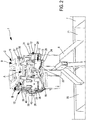
- the subject of the present invention is a device 1 for the production of blocking particles from at least one strip 2 of a material such as paper rolled up on a roll 3. It is specified that in the embodiment variant illustrated the device 1 is able to be fed by two strips 2 of material conveyed in parallel, coming from two rollers 3 superimposed on a reel 300, which advantageously makes it possible to contribute to improving the rates.
- the device 1 is supported by a base 10. It is actuated by a motor 8 and comprises means for conveying the strips 2 of material from an inlet zone 4, through deformation means of a section of the strips 2 and cutting means of said section, to an ejection zone 5.
- the latter communicates, by means of a hopper 6, with a tank 7 comprising two compartments 70, 71 each making it possible to recover the particles obtained from one of the two strips 2.
- the particulate recovery means obtained are provided with means for detecting their level of filling designed to cut the motor 8 from a predefined filling threshold. This prevents operators from having to be continually attentive to the fact that the tanks are not too full, which would harm a packaging respectful of the shape and quality of particulates manufactured.
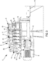
- the device 1 comprises a carousel 9 having a fixed ring 11 around which are rotated a plurality of modules 12.
- each module 12 comprises a pedestal 13 of parallelepiped shape, intended to be fixedly connected, by means of a support plate 14, integral with one of its lateral faces 20, with a driven belt 15 in rotation with respect to the fixed ring gear 11.
- the base 13 comprises two through-passages 16 of parallel axes X1, X2 extending between its upper face 17 and its lower face 18, in each of which a rod 19 is mounted to move in translation .
- Each rod 19 is intended to cooperate, during the displacement of the modules 12 around the fixed ring 11, with a folding matrix aligned with each of the axes X1, X2 of the through-passages 16, under the lower face 18 of the base 13 of which it solidarity.
- each folding matrix comprises an orifice 21, the shape of which determines that conferred on the strip section 2, pierced in a first plate 22, and a passage 27 of frustoconical section having an inlet opening of diameter d0. and an outlet opening of diameter d1 less than d0 , pierced in a second plate 24.
- the first and second plates 22, 24 extend in a plane perpendicular to the axes X1, X2 so that the first plate 22 is disposed between the lower face 18 of the base 13 and an upper face 25 of the second plate 24, in which extends the inlet opening of diameter d0 of the passage 23 of frustoconical section.
- first and second plates 22, 24 are arranged relative to the base 13 in such a way that each through passage 16 of the base 13 is aligned with an orifice 21 of the first plate 22 and a frustoconical passage 23 of the second plate 24. .
- each assembly consisting of a rod 19 and a folding die constitutes deformation means of a section of a strip 2, and is movable between an inactive state in which it is located.
- the module 12 considered is in the input zone 4, and in which the rod 19 is away from the folding die, and an active state that it adopts as the module 12 moves around the fixed ring 11 and wherein the rod 19 is progressively engaged through the orifice 21 and the frustoconical passage 23 of the folding die.
- Each module 12 of the device 1 also comprises cutting means defined by a guillotine 26, disposed in a plane parallel to a front face 27 of the base 13 which it is secured.
- Each guillotine 26 is constituted by a lower blade 28, fixedly connected to the plate 24, and an upper blade 29 mounted movable in translation along an axis parallel to an axis X1, X2 on the front face 27 of the base 13.
- the upper blade 29 and the front face 27 of the base 13 comprise means for guiding the displacement in translation of the upper blade 29 movable relative to the base 13.
- these translational guiding means comprise a rail 30 and a slideway 32 of axis parallel to the axes X1, X2, respectively fixed on a central zone of the inner face 31 of the upper blade 29, and formed on a central zone of the front face 27 of the base 13.
- the translation guiding means further comprise two oblong holes 33 of axes parallel to the axes X1, X2, each formed along a lateral edge 34, 35 of the upper blade 29 and with each of which cooperates a pin 36 suitably extending on the front face 27 of the base 13.
- each guillotine 26 is movable between an inactive state in which it is located when the module 12 in question is in the entry zone 4, and in which the upper blade 29 is moved away from the lower blade 28, and an active state that it adopts as the displacement of the module 12 around the fixed ring 11 and in which the upper blade 29 is progressively brought closer to the lower blade 28.
- each module 12 comprises a roller 37 integral with an arm 38, guided in a slide 39 formed around the periphery of the fixed ring 11 of the device 1.
- the roller 37 is able to cooperate with said deformation means and said cutting means of said module 12 for moving them between their respective inactive and active states, and vice versa, as it moves around the fixed ring gear 11 in the slide 39, specifically shaped to play such a cam role; that it will be described below.
- the arm 38 extending the roller 37 is integral with a bracket-shaped flange 40.
- the latter overlaps the base 13 so that a first leg 41 of the flange 40 extends in abutment against an upper end face 190 of each rod 19 in a plane perpendicular to the axes X1, X2 and a second tab 42 of the flange 40 extends in a plane parallel to the front face 27 of the base 13 opposite the outer face 43 of the movable upper blade 29.
- each of the connecting rods 44 comprises a first and a second parallel arm 45, 46, extending on either side of a central body 47, in opposite directions, perpendicular to the axes X1, X2.
- the first arm 45 is received in a housing 49 of the front face 27 of the base 13 and connected thereto by means of an axis engaged in a hole 48 of complementary shape that includes said housing 49.
- the second arm 46 is engaged to both in an "L" slot 50, having a section 51 of axis parallel to the axes X1, X2, formed in the second tab 42 of the flange 40 and in a slot 52 of axis perpendicular to the axes X1, X2 that has the movable upper blade 29.
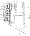
- the slide 39 comprises first, second and third portions A, B, C, succeeding one another between the input zone 4 and the ejection zone 5, and configured so that the first portion A defines for each module 12 a path in which its roller 37 extends in a plane P1 in which it is located relative to the base 13 at a distance such that it acts neither on the rods 19, nor on the upper blade 29, which remain spaced from the corresponding folding matrices, and the lower blade 28 and are therefore placed in their inactive state while the two bands 2 are progressively routed.
- the second and third portions B, C of the slide 11 define for each module 12 paths in which the roller 37 extends in planes P2, P3, P4 below the plane P1 and is located relative to the base 13 at distances such that the deformation means and the cutting means are in their active state, which corresponds for the deformation means to different successive positions in which the rods 19 are progressively pushed through the orifices 21 and the passages 23 to allow first the deformation of the section of each strip 2, until they are completely traversed and lead to the ejection of each deformed strip section 2 to a compartment 70, 71 of the tray 7.
- the active state of the guillotine 26 is reached through of displacement in translation of the flange 40 under the effect of the change of plane of the roller 37, which displacement in translation causes that of the movable blade 29. It should be noted that this The latter moves linearly thanks to the symmetrical movement of the rods 44 which generate a support on either side of the blade 29. Moreover, a bias on the edge of the movable blade 29 gives the progressivity to the cut.
- the device 1 according to the invention makes it possible to achieve the objectives previously described.
- the punching is no longer performed by a mechanical system of reciprocating and actuated by a rotary cam, but by a carousel system along which several modules 12 move in being driven by a belt 15, allows to remove any mechanical stop noise.
- the system according to the invention makes it possible to double the production rate of the particles with respect to the devices of the prior art by less mobilizing the operators.
- the device according to the invention makes it possible to work with two rollers simultaneously during one hour of operation. without human intervention since a cell will stop the device automatically in case of full tank 7.
- the device 1 according to the invention makes it possible to eliminate jamming problems and is suitable for many types of materials, in particular for all types of paper.
- the system implemented based on a carousel 9, pulls the strips 2 of material, which eliminates any jams at the blades of the guillotine 26, observed with the machines of the state of the technique in which the paper web is pushed into the deformation mechanism by a wheel.
- the device 1 according to the invention also makes it possible to produce particles of different size and shape by replacing only the modules 12 with other modules 12 comprising folding matrices of different shape and size.
- the device 1 according to the invention is easy to maintain and requires replacement of less frequent wear parts.
Landscapes
- Perforating, Stamping-Out Or Severing By Means Other Than Cutting (AREA)
- Folding Of Thin Sheet-Like Materials, Special Discharging Devices, And Others (AREA)
Abstract
La présente invention concerne un dispositif (1) pour la fabrication de particulaires de calage à partir d'au moins une bande (2) d'un matériau, ledit dispositif (1) étant actionné par un moteur (8) et comprenant des moyens d'acheminement de ladite bande (2) depuis une zone d'entrée (4), à travers des moyens de déformation d'un tronçon de la bande et des moyens de coupe dudit tronçon, jusqu'à une zone d'éjection (5) communiquant avec des moyens de récupération des particulaires obtenus. Il est caractérisé en ce qu'il comporte un carrousel (9) présentant une couronne fixe (11) autour de laquelle sont entraînés en rotation une pluralité de modules (12) sur chacun desquels sont montés mobiles entre un état inactif et un état actif les moyens de déformation et les moyens de coupe d'un tronçon de ladite bande (2), ladite couronne fixe (11) et lesdits modules (12) comportant des moyens conçus aptes à provoquer le déplacement desdits moyens de déformation et desdits moyens de coupe entre leur état inactif et leur état actif respectifs, et inversement, au cours du déplacement en rotation desdits modules (12) autour de ladite couronne fixe (11) .The present invention relates to a device (1) for the production of blocking particles from at least one strip (2) of a material, said device (1) being actuated by a motor (8) and comprising means for conveying said web (2) from an entrance zone (4) through deformation means of a section of the web and cutting means of said section to an ejection zone (5) communicating with means for recovering the particles obtained. It is characterized in that it comprises a carousel (9) having a fixed ring (11) around which are rotated a plurality of modules (12) on each of which are mounted movable between an inactive state and an active state. deformation means and the cutting means of a section of said strip (2), said fixed ring (11) and said modules (12) comprising means designed to cause the displacement of said deformation means and said cutting means between their inactive state and their respective active state, and vice versa, during the rotational displacement of said modules (12) around said fixed ring (11).
Description
La présente invention a pour objet un dispositif pour la fabrication de particulaires de calage à partir d'une bande d'un matériau tel que du papier, ledit dispositif comprenant des moyens d'acheminement de ladite bande de matériau depuis une zone d'entrée, à travers des moyens de déformation d'un tronçon de la bande et des moyens de coupe dudit tronçon, jusqu'à une zone d'éjection communiquant avec des moyens de récupération des particulaires obtenus, ledit dispositif étant actionné par un moteur.The present invention relates to a device for the manufacture of wedging particles from a strip of a material such as paper, said device comprising means for conveying said strip of material from an entrance zone, through means of deformation of a section of the strip and cutting means of said section, to an ejection zone communicating with particulate recovery means obtained, said device being actuated by a motor.
De plus en plus de produits sont actuellement commercialisés à distance et nécessitent par conséquent d'être transportés en vue de leur livraison à l'adresse souhaitée par le consommateur. Lors de leur conditionnement en vue de ce transport, ces produits sont disposés dans un emballage dans lequel, en fonction de leur nature, ils sont protégés des chocs et donc de leur détérioration par un matériau de calage. Afin d'éviter l'approvisionnement et le stockage de tels matériaux de calage, particulièrement volumineux et donc à l'origine d'un encombrement synonyme de frais importants, de nombreux professionnels cherchent aujourd'hui à les produire eux-mêmes au fil de leurs besoins directement sur le site d'emballage.More and more products are currently being marketed remotely and therefore need to be transported for delivery to the address desired by the consumer. When they are packaged for this transport, these products are placed in a packaging in which, depending on their nature, they are protected from shocks and therefore from being damaged by a setting material. In order to avoid the supply and storage of such particularly bulky blocking materials, which is the cause of congestion, which is synonymous with high costs, many professionals are now seeking to produce them themselves as they go along. needs directly on the packaging site.
Des machines spécifiquement conçues pour la fabrication de particulaires de calage à partir de bandes de matériau ont ainsi été développées pour répondre à un tel besoin. Elles ont pour autre avantage d'être généralement basées sur la transformation de matériaux recyclés, tels que du papier recyclé, plus respectueux de l'environnement que les particulaires en polystyrène classiques et plus agréable à manipuler aussi bien par les opérateurs que par les consommateurs.Machines specifically designed for the manufacture of cushioning particles from webs of material have thus been developed to meet such a need. They have the additional advantage of being generally based on the processing of recycled materials, such as recycled paper, which is more environmentally friendly than conventional polystyrene particulates and more pleasant to handle by both operators and consumers.
Néanmoins, il a pu être constaté que les différents modèles de machines disponibles à ce jour ne donnent pas entière satisfaction et présentent un certain nombre d'inconvénients que la présente invention a pour objectif de pallier.Nevertheless, it has been found that the different models of machines available to date do not give full satisfaction and have a number of disadvantages that the present invention aims to overcome.
En effet, il a notamment pu être observé qu'avec les dispositifs dans lesquels le poinçonnage est effectué par un système mécanique de va et vient, et les opérations de coupe sont réalisées au moyen d'une scie circulaire et de lames de couteaux, les utilisateurs rapportent de nombreux problèmes. En particulier, des phénomènes d'aplatissement des particulaires en sortie de machine et qui nuisent à leur effet de calage ont été notés. Par ailleurs, de telles machines s'avèrent bruyantes, posent des problèmes de bourrage, sont sensibles à l'hygrométrie et à la qualité du matériau employé, et ne sont pas totalement automatisées. De plus, elles sont considérées trop lentes, et peu pratiques du point de vue de la réalisation de sacs de particulaires. Enfin, elles nécessitent un entretien et un remplacement des pièces d'usures trop fréquents.Indeed, it has been observed in particular that with the devices in which the punching is performed by a mechanical system back and forth, and the cutting operations are performed by means of a circular saw and knife blades, the users report many problems. In particular, phenomena of flattening of the particles at the output of the machine and which adversely affect their wedging effect have been noted. Moreover, such machines are noisy, cause jamming problems, are sensitive to the hygrometry and quality of the material used, and are not fully automated. In addition, they are considered too slow, and impractical from the point of view of the realization of particulate sacks. Finally, they require maintenance and replacement of wear parts too frequent.
Par conséquent, la présente invention a pour objet de fournir une nouvelle solution permettant de pallier l'ensemble des inconvénients ci-dessus. En d'autres termes, elle entend proposer un dispositif pour la fabrication de particulaires de calage qui soit entièrement automatisé de manière à limiter au maximum les interventions des opérateurs, qui permette des cadences rapides, qui fonctionne convenablement en donnant lieu à des particulaires de qualité quelle que soit la nature du matériau de base employé et son hygrométrie, qui évite les phénomènes de bourrage, qui génère moins de bruit, nécessitant moins de maintenance et un remplacement moins fréquent de ses pièces.Therefore, the present invention aims to provide a new solution to overcome all of the above disadvantages. In other words, it intends to propose a device for the manufacture of particle calibration which is fully automated so as to minimize operator intervention, which allows fast rates, which works properly giving rise to quality particulates regardless of the nature of the base material used and its hygrometry, which avoids stuffing phenomena, which generates less noise, requiring less maintenance and less frequent replacement of its parts.
A cet effet, la présente invention concerne un dispositif du genre indiqué en préambule, caractérisé en ce qu'il comporte un carrousel présentant une couronne fixe autour de laquelle sont entraînés en rotation une pluralité de modules sur chacun desquels sont montés mobiles entre un état inactif et un état actif les moyens de déformation et les moyens de coupe d'un tronçon de ladite bande, ladite couronne fixe et lesdits modules comportant des moyens conçus aptes à provoquer le déplacement desdits moyens de déformation et desdits moyens de coupe entre leur état inactif et leur état actif respectifs, et inversement, au cours du déplacement en rotation desdits modules autour de ladite couronne fixe.To this end, the present invention relates to a device of the type indicated in the preamble, characterized in that it comprises a carousel having a fixed ring around which are rotated a plurality of modules on each of which are mounted movable between an inactive state and an active state the deformation means and the cutting means of a section of said strip, said fixed ring and said modules comprising means designed to cause the displacement of said deformation means and said cutting means between their inactive state and their respective active state, and vice versa, during the rotational movement of said modules around said fixed ring.
Conformément à une variante de réalisation préférentielle, chaque module comporte d'une part un socle d'allure parallélépipédique, supportant lesdits moyens de déformation et lesdits moyens de coupe, destiné à être relié fixement à une courroie entraînée en rotation par rapport à ladite couronne fixe, et d'autre part un galet, solidaire desdits moyens de déformation et desdits moyens de coupe, guidé dans une coulisse ménagée autour de la périphérie de la couronne fixe, ladite coulisse étant conformée de manière telle que lors de son déplacement autour de la couronne fixe, le galet agisse sur lesdits moyens de déformation et lesdits moyens de coupe pour les déplacer entre leurs états inactifs et actifs respectifs, et inversement.According to a preferred embodiment, each module comprises on the one hand a pedestal of parallelepiped shape, supporting said deformation means and said cutting means, intended to be fixedly connected to a belt driven in rotation with respect to said fixed ring gear. and on the other hand a roller, secured to said deformation means and said cutting means, guided in a slide arranged around the periphery of the fixed ring, said slide being shaped in such a way that during its movement around the ring fixed, the roller acts on said deformation means and said cutting means to move them between their respective inactive states and active, and vice versa.
Dans ce cas, lesdits moyens de déformation peuvent comporter un ensemble constitué par au moins une tige, montée mobile en translation dans un passage traversant d'axe X s'étendant entre une face supérieure et une face inférieure dudit socle, et au moins une matrice de pliage disposée dans l'axe X du passage traversant, sous la face inférieure dudit socle dont elle est solidaire.In this case, said deformation means may comprise an assembly constituted by at least one rod, mounted to move in translation in an X-axis through passage extending between an upper face and a lower face of said base, and at least one matrix folding disposed in the axis X of the through passage, under the underside of said base which it is integral.
L'invention prévoit en outre que lesdits moyens de coupe peuvent comporter une guillotine, disposée dans un plan parallèle à une face avant dudit socle dont elle est solidaire, et comportant une lame inférieure fixe et une lame supérieure montée mobile en translation le long d'un axe parallèle à l'axe X sur la face avant dudit socle.The invention further provides that said cutting means may comprise a guillotine disposed in a plane parallel to a front face of said base which it is integral with, and comprising a fixed lower blade and an upper blade mounted to move in translation along an axis parallel to the X axis on the front face of said base.
Une autre caractéristique de l'invention est définie par le fait que, dans cette variante de réalisation, ledit galet est solidaire d'une bride en forme d'équerre chevauchant ledit socle de manière telle qu'une première patte de la bride s'étende contre une face d'extrémité supérieure de ladite tige dans un plan perpendiculaire à l'axe X et qu'une seconde patte de la bride s'étende dans un plan parallèle à la face avant dudit socle vis à vis d'une face externe de ladite lame supérieure mobile, ladite seconde patte, ladite lame supérieure mobile et ladite face avant dudit socle étant reliées entre elles au moyen d'au moins une bielle.Another feature of the invention is defined by the fact that, in this embodiment, said roller is integral with a bracket-shaped flange overlapping said base such that a first leg of the flange extends against an upper end face of said rod in a plane perpendicular to the X axis and a second leg of the flange extends in a plane parallel to the front face of said base with respect to an outer face of said movable upper blade, said second leg, said movable upper blade and said front face of said base being interconnected by means of at least one connecting rod.
Conformément à l'invention, cette dernière comporte un premier et un second bras parallèles, s'étendant perpendiculairement à l'axe X, dans des directions opposées, de part et d'autre d'un corps central, le premier bras étant reçu dans un logement que comporte la face avant dudit socle et relié à cette dernière au moyen d'un axe engagé dans un trou de forme complémentaire formé dans ledit logement, tandis que le second axe est engagé à la fois dans une fente en « L » comportant un tronçon d'axe parallèle à l'axe X, formée dans la seconde patte de la bride et dans une fente d'axe perpendiculaire à l'axe X que comporte la lame supérieure mobile.According to the invention, the latter comprises a first and a second parallel arm, extending perpendicular to the axis X, in opposite directions, on either side of a central body, the first arm being received in a housing that comprises the front face of said base and connected thereto by means of an axis engaged in a hole of complementary shape formed in said housing, while the second axis is engaged both in an "L" slot comprising a section of axis parallel to the X axis, formed in the second leg of the flange and in a slot of axis perpendicular to the axis X that comprises the movable upper blade.
De manière avantageuse, l'invention prévoit également que la lame supérieure et la face avant dudit socle comportent des moyens de guidage du déplacement en translation de la lame supérieure mobile par rapport audit socle.Advantageously, the invention also provides that the upper blade and the front face of said base comprise means for guiding the displacement in translation of the upper blade movable relative to said base.
Lesdits moyens de guidage peuvent comporter un rail et une glissière d'axes parallèles à l'axe X, respectivement formés sur une zone centrale d'une face interne de la lame supérieure et une zone centrale de la face avant dudit socle, ainsi que deux trous oblongs d'axes parallèles à l'axe X, formés chacun le long d'un bord latéral de la lame supérieure et avec chacun desquels coopère un téton s'étendant de manière appropriée sur la face avant du socle.Said guide means may comprise a rail and a slideway of axes parallel to the axis X, respectively formed on a central zone of an inner face of the upper blade and a central zone of the front face of said base, and two oblong holes of axes parallel to the X axis, each formed along a lateral edge of the upper blade and with each of which cooperates a nipple extending appropriately on the front face of the base.
Par ailleurs, selon une autre caractéristique de l'invention, la matrice de pliage comporte au moins un orifice, dont la forme détermine celle conférée au tronçon de bande, percé dans une première plaque, et au moins un passage de section tronconique percé dans une seconde plaque, ledit passage présentant une ouverture d'entrée de diamètre d0 et une ouverture de sortie de diamètre d1 inférieur à d0, ladite première plaque étant disposée entre la face inférieure du socle et une face supérieure de la seconde plaque, dans laquelle s'étend l'ouverture d'entrée dudit passage de section tronconique, et lesdites premières et seconde plaques étant disposées par rapport audit socle de manière telle que ledit passage traversant dudit socle, ledit orifice de ladite première plaque et ledit passage tronconique de ladite seconde plaque sont coaxiaux.Furthermore, according to another characteristic of the invention, the folding matrix comprises at least one orifice, the shape of which determines that conferred on the strip section, pierced in a first plate, and at least one frustoconical section passage pierced in a second plate, said passage having an inlet opening of diameter d0 and an outlet opening of diameter d1 less than d0, said first plate being disposed between the lower face of the base and an upper face of the second plate, in which s' extends the inlet opening of said frustoconical section passage, and said first and second plates being arranged with respect to said base in such a way that said through passage of said base, said orifice of said first plate and said frustoconical passage of said second plate are coaxial.
Dans une telle configuration, la lame inférieure de la guillotine est prévue solidaire de la seconde plaque.In such a configuration, the lower blade of the guillotine is provided integral with the second plate.
Conformément à une autre caractéristique de l'invention, ladite coulisse comporte une première, une seconde et une troisième portions se succédant entre la zone d'entrée et la zone de sortie, et configurées de telle sorte que la première portion définit pour le module une trajectoire dans laquelle le galet s'étend par rapport au socle à une distance telle que les moyens de déformation et les moyens de coupe sont placés dans leur état inactif, tandis que la deuxième et la troisième portions définissent pour le module des trajectoires dans lesquelles le galet s'étend par rapport au socle à des distances telles que les moyens de déformation et les moyens de coupe sont dans leur état actif, lequel correspond pour les moyens de déformation à différentes positions successives dans lesquelles ils permettent d'abord la déformation du tronçon de bande via la matrice de pliage puis l'éjection du tronçon de bande déformé de la matrice de pliage.According to another characteristic of the invention, said slide comprises a first, a second and a third portion succeeding between the input zone and the output zone, and configured so that the first portion defines for the module a trajectory in which the roller extends relative to the base at a distance such that the deformation means and the cutting means are placed in their inactive state, while the second and third portions define for the module paths in which the roller extends with respect to the base at distances such that the deformation means and the cutting means are in their active state, which corresponds for the deformation means to different successive positions in which they allow first the deformation of the section banding via the folding die and then ejecting the deformed band section of the folding die.
De plus, l'invention prévoit encore que les moyens de récupération des particulaires obtenus sont avantageusement pourvus de moyens de détection de leur niveau de remplissage conçus aptes à couper ledit moteur à partir d'un seuil de remplissage prédéfini.In addition, the invention further provides that the particulate recovery means obtained are advantageously provided with means for detecting their level of filling designed to cut said motor from a predefined filling threshold.
D'autres caractéristiques et avantages de l'invention ressortiront de la description détaillée qui va suivre, se rapportant à un exemple de réalisation du dispositif selon l'invention donné uniquement à titre indicatif et non limitatif.Other features and advantages of the invention will emerge from the detailed description which follows, referring to an embodiment of the device according to the invention given solely for information and not limitation.
La compréhension de cette description sera facilitée en se référant aux dessins joints, dans lesquels :
- La
figure 1 illustre une vue d'ensemble d'une variante de réalisation du dispositif selon l'invention, - Les
figures 2 à 4 sont des vues partielles agrandies du dispositif de lafigure 1 prises entre la zone d'entrée et la zone d'éjection dans le sens du déplacement des modules, - La
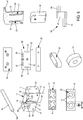
figure 5 est une vue d'un module du dispositif selon l'invention, - La
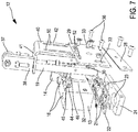
figure 6 représente les différentes pièces constitutives du module de lafigure 5 , et - La
figure 7 est une vue en perspective éclatée du module de lafigure 5 .
- The
figure 1 illustrates an overview of an alternative embodiment of the device according to the invention, - The
Figures 2 to 4 are partial enlarged views of the device of thefigure 1 taken between the input zone and the ejection zone in the direction of movement of the modules, - The
figure 5 is a view of a module of the device according to the invention, - The
figure 6 represents the various component parts of the module of thefigure 5 , and - The
figure 7 is an exploded perspective view of the module of thefigure 5 .
La présente invention a pour objet un dispositif 1 pour la fabrication de particulaires de calage à partir d'au moins une bande 2 d'un matériau tel que du papier, enroulée sur un rouleau 3. Il est précisé que dans la variante de réalisation illustrée, le dispositif 1 est apte à être alimenté par deux bandes 2 de matériau acheminées parallèlement, en provenance de deux rouleaux 3 superposés sur un enrouleur 300, ce qui permet avantageusement de contribuer à améliorer les cadences.The subject of the present invention is a device 1 for the production of blocking particles from at least one
De manière classique, le dispositif 1 est supporté par un piètement 10. Il est actionné par un moteur 8 et comprend des moyens d'acheminement des bandes 2 de matériau depuis une zone d'entrée 4, à travers des moyens de déformation d'un tronçon des bandes 2 et des moyens de coupe dudit tronçon, jusqu'à une zone d'éjection 5. Cette dernière communique, au moyen d'une trémie 6, avec un bac 7 comportant deux compartiments 70, 71 permettant chacun de récupérer les particulaires obtenus à partir d'une des deux bandes 2. A ce propos, il convient de noter que, de manière avantageuse, l'invention a prévu que les moyens de récupération des particulaires obtenus sont pourvus de moyens de détection de leur niveau de remplissage conçus aptes à couper le moteur 8 à partir d'un seuil de remplissage prédéfini. Ceci permet d'éviter aux opérateurs d'avoir à être continuellement attentifs au fait que les bac ne soient pas trop remplis, ce qui nuirait à un conditionnement respectueux de la forme et de la qualité des particulaires fabriqués.Conventionally, the device 1 is supported by a
Conformément à l'invention, le dispositif 1 comporte un carrousel 9 présentant une couronne fixe 11 autour de laquelle sont entraînés en rotation une pluralité de modules 12.According to the invention, the device 1 comprises a
En référence à la
Conformément à l'invention, chaque matrice de pliage comporte un orifice 21, dont la forme détermine celle conférée au tronçon de bande 2, percé dans une première plaque 22, et un passage 23 de section tronconique présentant une ouverture d'entrée de diamètre d0 et une ouverture de sortie de diamètre d1 inférieur à d0, percé dans une seconde plaque 24. Tel que visible à la
Comme il sera décrit plus en détail ci-dessous, chaque ensemble constitué par une tige 19 et une matrice de pliage constitue des moyens de déformation d'un tronçon d'une bande 2, et est mobile entre un état inactif dans lequel il se trouve lorsque le module 12 considéré se trouve dans la zone d'entrée 4, et dans lequel la tige 19 est éloignée de la matrice de pliage, et un état actif qu'il adopte au fur et à mesure du déplacement du module 12 autour de la couronne fixe 11 et dans lequel la tige 19 est progressivement engagée à travers l'orifice 21 puis le passage tronconique 23 de la matrice de pliage.As will be described in more detail below, each assembly consisting of a
Chaque module 12 du dispositif 1 selon l'invention comporte également des moyens de coupe définis par une guillotine 26, disposée dans un plan parallèle à une face avant 27 du socle 13 dont elle est solidaire. Chaque guillotine 26 est constituée par une lame inférieure 28, reliée fixement à la plaque 24, et une lame supérieure 29 montée mobile en translation le long d'un axe parallèle à un axe X1, X2 sur la face avant 27 du socle 13.Each
En fait, la lame supérieure 29 et la face avant 27 du socle 13 comportent des moyens de guidage du déplacement en translation de la lame supérieure 29 mobile par rapport au socle 13.In fact, the
Dans la variante de réalisation illustrée, ces moyens de guidage en translation comportent un rail 30 et une glissière 32 d'axe parallèles aux axes X1, X2, respectivement fixé sur une zone centrale de la face interne 31 de la lame supérieure 29, et formée sur une zone centrale de la face avant 27 du socle 13. Les moyens de guidage en translation comportent en outre deux trous oblongs 33 d'axes parallèles aux axes X1, X2, formés chacun le long d'un bord latéral 34, 35 de la lame supérieure 29 et avec chacun desquels coopère un téton 36 s'étendant de manière appropriée sur la face avant 27 du socle 13.In the embodiment variant illustrated, these translational guiding means comprise a
A l'instar des moyens de déformation que comporte chaque module 12, chaque guillotine 26 est mobile entre un état inactif dans lequel elle se trouve lorsque le module 12 considéré se trouve dans la zone d'entrée 4, et dans lequel la lame supérieure 29 est écartée de la lame inférieure 28, et un état actif qu'elle adopte au fur et à mesure du déplacement du module 12 autour de la couronne fixe 11 et dans lequel la lame supérieure 29 est progressivement rapprochée de la lame inférieure 28.Like the deformation means that each
Par ailleurs, chaque module 12 comporte un galet 37 solidaire d'un bras 38, guidé dans une coulisse 39 ménagée autour de la périphérie de la couronne fixe 11 du dispositif 1. Conformément à l'invention, le galet 37 est apte à coopérer avec lesdits moyens de déformation et lesdits moyens de coupe dudit module 12 pour les déplacer entre leurs états inactifs et actifs respectifs, et inversement, lors de son déplacement autour de la couronne fixe 11 dans la coulisse 39, spécifiquement conformée pour jouer un rôle de came tel qu'il sera décrit ci-dessous.Furthermore, each
En référence aux figures, sur chaque module 12, le bras 38 prolongeant le galet 37 est solidaire d'une bride 40 en forme d'équerre. Cette dernière chevauche le socle 13 de manière telle qu'une première patte 41 de la bride 40 s'étende en appui contre une face d'extrémité supérieure 190 de chaque tige 19 dans un plan perpendiculaire aux axes X1, X2 et qu'une seconde patte 42 de la bride 40 s'étende dans un plan parallèle à la face avant 27 du socle 13 vis à vis de la face externe 43 de la lame supérieure mobile 29.Referring to the figures, on each
Par ailleurs, la seconde patte 42, la lame supérieure mobile 29 et la face avant 27 du socle coopèrent entre elles au moyen de deux bielles 44 identiques. En fait chacune des bielles 44 comporte un premier et un second bras parallèles 45, 46, s'étendant de part et d'autre d'un corps central 47, dans des directions opposées, perpendiculairement aux axes X1, X2. Le premier bras 45 est reçu dans un logement 49 de la face avant 27 du socle 13 et relié à cette dernière au moyen d'un axe engagé dans un trou 48 de forme complémentaire que comporte ledit logement 49. Le second bras 46 est engagé à la fois dans une fente en « L » 50, comportant un tronçon 51 d'axe parallèle aux axes X1, X2, formée dans la seconde patte 42 de la bride 40 et dans une fente 52 d'axe perpendiculaire aux axes X1, X2 que comporte la lame supérieure mobile 29.Furthermore, the
Conformément à l'invention, la coulisse 39 comporte une première, une seconde et une troisième portions A, B, C, se succédant entre la zone d'entrée 4 et la zone d'éjection 5, et configurées de telle sorte que la première portion A définisse pour chaque module 12 une trajectoire dans laquelle son galet 37 s'étend dans un plan P1 dans lequel il est situé par rapport au socle 13 à une distance telle qu'il n'agisse ni sur les tiges 19, ni sur la lame supérieure 29, qui demeurent écartées des matrices de pliage correspondantes, et de la lame inférieure 28 et sont donc placés dans leur état inactif alors que les deux bandes 2 sont progressivement acheminées. Les deuxièmes et troisième portions B, C de la coulisse 11 définissent pour chaque module 12 des trajectoires dans lesquelles le galet 37 s'étend dans des plans P2, P3, P4 inférieurs au plan P1 et est situé par rapport au socle 13 à des distances telles que les moyens de déformation et les moyens de coupe sont dans leur état actif, lequel correspond pour les moyens de déformation à différentes positions successives dans lesquelles les tiges 19 sont progressivement enfoncées à travers les orifices 21 et les passages 23 pour permettre d'abord la déformation du tronçon de chaque bande 2, jusqu'à les traverser complètement et conduire à l'éjection de chaque tronçon de bande 2 déformé vers un compartiment 70, 71 du bac 7. L'état actif de la guillotine 26 est atteint au travers du déplacement en translation de la bride 40 sous l'effet du changement de plan du galet 37, lequel déplacement en translation entraîne celui de la lame mobile 29. Il est à noter que cette dernière se déplace de manière linéaire grâce au mouvement symétrique des bielles 44 qui génèrent un appui de part et d'autre de la lame 29. Par ailleurs, un biais sur l'arête de la lame mobile 29 donne la progressivité à la coupe.According to the invention, the
Grâce à la structure qui vient d'être décrite, le dispositif 1 selon l'invention permet d'atteindre les objectifs préalablement décrits. En particulier, du fait que le poinçonnage ne s'effectue plus par un système mécanique de va et vient actionné par une came rotative, mais par un système carrousel le long duquel plusieurs modules 12 se déplacent en étant entraînés par une courroie 15, permet de supprimer tout bruit de butée mécanique. Il a en outre pu être observé que le système selon l'invention permet de doubler la cadence de fabrication des particulaires par rapport aux dispositifs de l'art antérieur en mobilisant moins les opérateurs. En effet, le dispositif selon l'invention permet de travailler avec deux rouleaux simultanément pendant une heure de fonctionnement sans intervention humaine puisqu'une cellule arrêtera le dispositif automatiquement en cas de bac 7 plein.Thanks to the structure that has just been described, the device 1 according to the invention makes it possible to achieve the objectives previously described. In particular, because the punching is no longer performed by a mechanical system of reciprocating and actuated by a rotary cam, but by a carousel system along which
En outre, cet arrêt automatique de la machine en cas de bac 7 plein permet de supprimer les problèmes de tassement et d'écrasement des particulaires.In addition, this automatic shutdown of the machine in the case of
Par l'absence de scie circulaire, le dispositif 1 selon l'invention permet de supprimer les problèmes de bourrage et est adapté à de nombreux type de matériaux, en particulier à tous les types de papier.By the absence of circular saw, the device 1 according to the invention makes it possible to eliminate jamming problems and is suitable for many types of materials, in particular for all types of paper.
De plus, le système mis en oeuvre, reposant sur un carrousel 9, permet de tirer les bandes 2 de matériau, ce qui supprime tous les éventuels bourrages au niveau des lames de la guillotine 26, observés avec les machines de l'état de la technique dans lesquelles la bande de papier est poussée dans la mécanique de déformation par une roue.In addition, the system implemented, based on a
Par ailleurs, le dispositif 1 selon l'invention permet également de produire des particulaires de taille et de forme différente en remplaçant uniquement les modules 12 par d'autres modules 12 comportant des matrices de pliage de forme et de dimension différentes.Moreover, the device 1 according to the invention also makes it possible to produce particles of different size and shape by replacing only the
Egalement, du fait d'une structure simplifiée et d'un fonctionnement amélioré, le dispositif 1 selon l'invention est d'un entretien facilité et nécessite un remplacement des pièces d'usure moins fréquent.Also, because of a simplified structure and improved operation, the device 1 according to the invention is easy to maintain and requires replacement of less frequent wear parts.
Claims (12)
Applications Claiming Priority (1)
| Application Number | Priority Date | Filing Date | Title |
|---|---|---|---|
| FR1757578A FR3070024A1 (en) | 2017-08-08 | 2017-08-08 | DEVICE FOR THE PRODUCTION OF A TIMING MATERIAL |
Publications (1)
| Publication Number | Publication Date |
|---|---|
| EP3441218A1 true EP3441218A1 (en) | 2019-02-13 |
Family
ID=59930603
Family Applications (1)
| Application Number | Title | Priority Date | Filing Date |
|---|---|---|---|
| EP18187261.5A Withdrawn EP3441218A1 (en) | 2017-08-08 | 2018-08-03 | Device for manufacturing a packaging material |
Country Status (2)
| Country | Link |
|---|---|
| EP (1) | EP3441218A1 (en) |
| FR (1) | FR3070024A1 (en) |
Citations (2)
| Publication number | Priority date | Publication date | Assignee | Title |
|---|---|---|---|---|
| US20040108243A1 (en) * | 2002-12-04 | 2004-06-10 | Philippe Jeannin | Packaging material and method and device for producing the same |
| US20140274645A1 (en) * | 2013-03-15 | 2014-09-18 | Pregis Innovative Packaging Inc. | Tear-assist blade |
-
2017
- 2017-08-08 FR FR1757578A patent/FR3070024A1/en not_active Ceased
-
2018
- 2018-08-03 EP EP18187261.5A patent/EP3441218A1/en not_active Withdrawn
Patent Citations (2)
| Publication number | Priority date | Publication date | Assignee | Title |
|---|---|---|---|---|
| US20040108243A1 (en) * | 2002-12-04 | 2004-06-10 | Philippe Jeannin | Packaging material and method and device for producing the same |
| US20140274645A1 (en) * | 2013-03-15 | 2014-09-18 | Pregis Innovative Packaging Inc. | Tear-assist blade |
Also Published As
| Publication number | Publication date |
|---|---|
| FR3070024A1 (en) | 2019-02-15 |
Similar Documents
| Publication | Publication Date | Title |
|---|---|---|
| EP2337677B1 (en) | Device for transporting and folding elements in sheets | |
| EP3038954B1 (en) | Method for transporting and turning flat objects | |
| EP2914523B1 (en) | Device for holding a flat sheet-like element circulating in a treatment machine | |
| EP2976279B1 (en) | Device for ejecting a flat object during conveying | |
| EP2834178B1 (en) | Non-stop gate device for forming machine | |
| EP2391501B1 (en) | Folding device and method for folding-gluing machine | |
| WO2012116781A1 (en) | Tape paying out device for stamping machine | |
| EP2964556B1 (en) | Device for transporting flat elements | |
| EP2704973B1 (en) | Device for stacking sheets of paper or similar | |
| WO2012034649A1 (en) | Device for guiding strips for a stamping machine | |
| EP2585258B1 (en) | Supporting device for a workstation of a profiling machine | |
| CA2698423C (en) | High-capacity mail receiving device | |
| EP2196293B1 (en) | Cutter for decor for tappered support and device for forming tappered support and laying a decor comprising such a cutter | |
| WO2014154333A1 (en) | Device for pivoting flat objects | |
| EP3441218A1 (en) | Device for manufacturing a packaging material | |
| EP2772457A1 (en) | Facility to assist with packaging items | |
| FR2937280A1 (en) | DOCUMENT PROCESSING MACHINE WITH IMPROVED TRAINING. | |
| FR2740762A1 (en) | DEVICE FOR STACKING CARD-SHAPED PRODUCTS | |
| EP2481697B1 (en) | Piling device for mail items processing machine | |
| EP3331673B1 (en) | Bread cutting machine with a support surface for the bread which has a slit for the cutting blade | |
| FR2896722A1 (en) | OPTIMIZED TRANSPORT DEVICE FOR MAIL PROCESSING MACHINE | |
| FR2490457A1 (en) | MACHINE FOR ASSEMBLING FILLED WAFERS | |
| FR2725661A1 (en) | Continuous compaction appts. esp. for combustible waste |
Legal Events
| Date | Code | Title | Description |
|---|---|---|---|
| PUAI | Public reference made under article 153(3) epc to a published international application that has entered the european phase |
Free format text: ORIGINAL CODE: 0009012 |
|
| AK | Designated contracting states |
Kind code of ref document: A1 Designated state(s): AL AT BE BG CH CY CZ DE DK EE ES FI FR GB GR HR HU IE IS IT LI LT LU LV MC MK MT NL NO PL PT RO RS SE SI SK SM TR |
|
| AX | Request for extension of the european patent |
Extension state: BA ME |
|
| STAA | Information on the status of an ep patent application or granted ep patent |
Free format text: STATUS: THE APPLICATION IS DEEMED TO BE WITHDRAWN |
|
| 18D | Application deemed to be withdrawn |
Effective date: 20190814 |