EP3441218A1 - Vorrichtung für die herstellung von verkeilungs-/füllmaterial - Google Patents
Vorrichtung für die herstellung von verkeilungs-/füllmaterial Download PDFInfo
- Publication number
- EP3441218A1 EP3441218A1 EP18187261.5A EP18187261A EP3441218A1 EP 3441218 A1 EP3441218 A1 EP 3441218A1 EP 18187261 A EP18187261 A EP 18187261A EP 3441218 A1 EP3441218 A1 EP 3441218A1
- Authority
- EP
- European Patent Office
- Prior art keywords
- base
- axis
- section
- face
- deformation
- Prior art date
- Legal status (The legal status is an assumption and is not a legal conclusion. Google has not performed a legal analysis and makes no representation as to the accuracy of the status listed.)
- Withdrawn
Links
- 238000004519 manufacturing process Methods 0.000 title abstract description 7
- 239000005022 packaging material Substances 0.000 title 1
- 238000005520 cutting process Methods 0.000 claims abstract description 27
- 239000000463 material Substances 0.000 claims abstract description 16
- 238000006073 displacement reaction Methods 0.000 claims abstract description 12
- 239000002245 particle Substances 0.000 claims abstract description 12
- 230000000903 blocking effect Effects 0.000 claims abstract description 4
- 239000011159 matrix material Substances 0.000 claims description 6
- 238000011084 recovery Methods 0.000 claims description 5
- 230000000295 complement effect Effects 0.000 claims description 3
- 238000004806 packaging method and process Methods 0.000 description 3
- 230000000694 effects Effects 0.000 description 2
- 238000012423 maintenance Methods 0.000 description 2
- NJPPVKZQTLUDBO-UHFFFAOYSA-N novaluron Chemical compound C1=C(Cl)C(OC(F)(F)C(OC(F)(F)F)F)=CC=C1NC(=O)NC(=O)C1=C(F)C=CC=C1F NJPPVKZQTLUDBO-UHFFFAOYSA-N 0.000 description 2
- 238000004080 punching Methods 0.000 description 2
- 239000004793 Polystyrene Substances 0.000 description 1
- 230000002411 adverse Effects 0.000 description 1
- 235000021183 entrée Nutrition 0.000 description 1
- 238000000034 method Methods 0.000 description 1
- 230000001483 mobilizing effect Effects 0.000 description 1
- 210000002445 nipple Anatomy 0.000 description 1
- 229920002223 polystyrene Polymers 0.000 description 1
- 230000035939 shock Effects 0.000 description 1
- 238000003860 storage Methods 0.000 description 1
Images

Classifications
-
- B—PERFORMING OPERATIONS; TRANSPORTING
- B31—MAKING ARTICLES OF PAPER, CARDBOARD OR MATERIAL WORKED IN A MANNER ANALOGOUS TO PAPER; WORKING PAPER, CARDBOARD OR MATERIAL WORKED IN A MANNER ANALOGOUS TO PAPER
- B31D—MAKING ARTICLES OF PAPER, CARDBOARD OR MATERIAL WORKED IN A MANNER ANALOGOUS TO PAPER, NOT PROVIDED FOR IN SUBCLASSES B31B OR B31C
- B31D5/00—Multiple-step processes for making three-dimensional articles ; Making three-dimensional articles
- B31D5/0039—Multiple-step processes for making three-dimensional articles ; Making three-dimensional articles for making dunnage or cushion pads
- B31D5/0043—Multiple-step processes for making three-dimensional articles ; Making three-dimensional articles for making dunnage or cushion pads including crumpling flat material
-
- B—PERFORMING OPERATIONS; TRANSPORTING
- B31—MAKING ARTICLES OF PAPER, CARDBOARD OR MATERIAL WORKED IN A MANNER ANALOGOUS TO PAPER; WORKING PAPER, CARDBOARD OR MATERIAL WORKED IN A MANNER ANALOGOUS TO PAPER
- B31D—MAKING ARTICLES OF PAPER, CARDBOARD OR MATERIAL WORKED IN A MANNER ANALOGOUS TO PAPER, NOT PROVIDED FOR IN SUBCLASSES B31B OR B31C
- B31D2205/00—Multiple-step processes for making three-dimensional articles
- B31D2205/0005—Multiple-step processes for making three-dimensional articles for making dunnage or cushion pads
- B31D2205/0011—Multiple-step processes for making three-dimensional articles for making dunnage or cushion pads including particular additional operations
- B31D2205/0017—Providing stock material in a particular form
- B31D2205/0023—Providing stock material in a particular form as web from a roll
-
- B—PERFORMING OPERATIONS; TRANSPORTING
- B31—MAKING ARTICLES OF PAPER, CARDBOARD OR MATERIAL WORKED IN A MANNER ANALOGOUS TO PAPER; WORKING PAPER, CARDBOARD OR MATERIAL WORKED IN A MANNER ANALOGOUS TO PAPER
- B31D—MAKING ARTICLES OF PAPER, CARDBOARD OR MATERIAL WORKED IN A MANNER ANALOGOUS TO PAPER, NOT PROVIDED FOR IN SUBCLASSES B31B OR B31C
- B31D2205/00—Multiple-step processes for making three-dimensional articles
- B31D2205/0005—Multiple-step processes for making three-dimensional articles for making dunnage or cushion pads
- B31D2205/0011—Multiple-step processes for making three-dimensional articles for making dunnage or cushion pads including particular additional operations
- B31D2205/0047—Feeding, guiding or shaping the material
-
- B—PERFORMING OPERATIONS; TRANSPORTING
- B31—MAKING ARTICLES OF PAPER, CARDBOARD OR MATERIAL WORKED IN A MANNER ANALOGOUS TO PAPER; WORKING PAPER, CARDBOARD OR MATERIAL WORKED IN A MANNER ANALOGOUS TO PAPER
- B31D—MAKING ARTICLES OF PAPER, CARDBOARD OR MATERIAL WORKED IN A MANNER ANALOGOUS TO PAPER, NOT PROVIDED FOR IN SUBCLASSES B31B OR B31C
- B31D2205/00—Multiple-step processes for making three-dimensional articles
- B31D2205/0005—Multiple-step processes for making three-dimensional articles for making dunnage or cushion pads
- B31D2205/0011—Multiple-step processes for making three-dimensional articles for making dunnage or cushion pads including particular additional operations
- B31D2205/0058—Cutting; Individualising the final products
-
- B—PERFORMING OPERATIONS; TRANSPORTING
- B31—MAKING ARTICLES OF PAPER, CARDBOARD OR MATERIAL WORKED IN A MANNER ANALOGOUS TO PAPER; WORKING PAPER, CARDBOARD OR MATERIAL WORKED IN A MANNER ANALOGOUS TO PAPER
- B31D—MAKING ARTICLES OF PAPER, CARDBOARD OR MATERIAL WORKED IN A MANNER ANALOGOUS TO PAPER, NOT PROVIDED FOR IN SUBCLASSES B31B OR B31C
- B31D2205/00—Multiple-step processes for making three-dimensional articles
- B31D2205/0005—Multiple-step processes for making three-dimensional articles for making dunnage or cushion pads
- B31D2205/0011—Multiple-step processes for making three-dimensional articles for making dunnage or cushion pads including particular additional operations
- B31D2205/007—Delivering
Definitions
- the present invention relates to a device for the manufacture of wedging particles from a strip of a material such as paper, said device comprising means for conveying said strip of material from an entrance zone, through means of deformation of a section of the strip and cutting means of said section, to an ejection zone communicating with particulate recovery means obtained, said device being actuated by a motor.
- Machines specifically designed for the manufacture of cushioning particles from webs of material have thus been developed to meet such a need. They have the additional advantage of being generally based on the processing of recycled materials, such as recycled paper, which is more environmentally friendly than conventional polystyrene particulates and more pleasant to handle by both operators and consumers.
- the present invention aims to provide a new solution to overcome all of the above disadvantages.
- it intends to propose a device for the manufacture of particle calibration which is fully automated so as to minimize operator intervention, which allows fast rates, which works properly giving rise to quality particulates regardless of the nature of the base material used and its hygrometry, which avoids stuffing phenomena, which generates less noise, requiring less maintenance and less frequent replacement of its parts.
- the present invention relates to a device of the type indicated in the preamble, characterized in that it comprises a carousel having a fixed ring around which are rotated a plurality of modules on each of which are mounted movable between an inactive state and an active state the deformation means and the cutting means of a section of said strip, said fixed ring and said modules comprising means designed to cause the displacement of said deformation means and said cutting means between their inactive state and their respective active state, and vice versa, during the rotational movement of said modules around said fixed ring.
- each module comprises on the one hand a pedestal of parallelepiped shape, supporting said deformation means and said cutting means, intended to be fixedly connected to a belt driven in rotation with respect to said fixed ring gear. and on the other hand a roller, secured to said deformation means and said cutting means, guided in a slide arranged around the periphery of the fixed ring, said slide being shaped in such a way that during its movement around the ring fixed, the roller acts on said deformation means and said cutting means to move them between their respective inactive states and active, and vice versa.
- said deformation means may comprise an assembly constituted by at least one rod, mounted to move in translation in an X-axis through passage extending between an upper face and a lower face of said base, and at least one matrix folding disposed in the axis X of the through passage, under the underside of said base which it is integral.
- said cutting means may comprise a guillotine disposed in a plane parallel to a front face of said base which it is integral with, and comprising a fixed lower blade and an upper blade mounted to move in translation along an axis parallel to the X axis on the front face of said base.
- roller is integral with a bracket-shaped flange overlapping said base such that a first leg of the flange extends against an upper end face of said rod in a plane perpendicular to the X axis and a second leg of the flange extends in a plane parallel to the front face of said base with respect to an outer face of said movable upper blade, said second leg, said movable upper blade and said front face of said base being interconnected by means of at least one connecting rod.
- the latter comprises a first and a second parallel arm, extending perpendicular to the axis X, in opposite directions, on either side of a central body, the first arm being received in a housing that comprises the front face of said base and connected thereto by means of an axis engaged in a hole of complementary shape formed in said housing, while the second axis is engaged both in an "L" slot comprising a section of axis parallel to the X axis, formed in the second leg of the flange and in a slot of axis perpendicular to the axis X that comprises the movable upper blade.
- the invention also provides that the upper blade and the front face of said base comprise means for guiding the displacement in translation of the upper blade movable relative to said base.
- Said guide means may comprise a rail and a slideway of axes parallel to the axis X, respectively formed on a central zone of an inner face of the upper blade and a central zone of the front face of said base, and two oblong holes of axes parallel to the X axis, each formed along a lateral edge of the upper blade and with each of which cooperates a nipple extending appropriately on the front face of the base.
- the folding matrix comprises at least one orifice, the shape of which determines that conferred on the strip section, pierced in a first plate, and at least one frustoconical section passage pierced in a second plate, said passage having an inlet opening of diameter d0 and an outlet opening of diameter d1 less than d0, said first plate being disposed between the lower face of the base and an upper face of the second plate, in which s' extends the inlet opening of said frustoconical section passage, and said first and second plates being arranged with respect to said base in such a way that said through passage of said base, said orifice of said first plate and said frustoconical passage of said second plate are coaxial.
- the lower blade of the guillotine is provided integral with the second plate.
- said slide comprises a first, a second and a third portion succeeding between the input zone and the output zone, and configured so that the first portion defines for the module a trajectory in which the roller extends relative to the base at a distance such that the deformation means and the cutting means are placed in their inactive state, while the second and third portions define for the module paths in which the roller extends with respect to the base at distances such that the deformation means and the cutting means are in their active state, which corresponds for the deformation means to different successive positions in which they allow first the deformation of the section banding via the folding die and then ejecting the deformed band section of the folding die.
- the invention further provides that the particulate recovery means obtained are advantageously provided with means for detecting their level of filling designed to cut said motor from a predefined filling threshold.
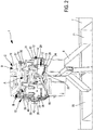
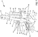
- the subject of the present invention is a device 1 for the production of blocking particles from at least one strip 2 of a material such as paper rolled up on a roll 3. It is specified that in the embodiment variant illustrated the device 1 is able to be fed by two strips 2 of material conveyed in parallel, coming from two rollers 3 superimposed on a reel 300, which advantageously makes it possible to contribute to improving the rates.
- the device 1 is supported by a base 10. It is actuated by a motor 8 and comprises means for conveying the strips 2 of material from an inlet zone 4, through deformation means of a section of the strips 2 and cutting means of said section, to an ejection zone 5.
- the latter communicates, by means of a hopper 6, with a tank 7 comprising two compartments 70, 71 each making it possible to recover the particles obtained from one of the two strips 2.
- the particulate recovery means obtained are provided with means for detecting their level of filling designed to cut the motor 8 from a predefined filling threshold. This prevents operators from having to be continually attentive to the fact that the tanks are not too full, which would harm a packaging respectful of the shape and quality of particulates manufactured.
- the device 1 comprises a carousel 9 having a fixed ring 11 around which are rotated a plurality of modules 12.
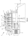
- each module 12 comprises a pedestal 13 of parallelepiped shape, intended to be fixedly connected, by means of a support plate 14, integral with one of its lateral faces 20, with a driven belt 15 in rotation with respect to the fixed ring gear 11.
- the base 13 comprises two through-passages 16 of parallel axes X1, X2 extending between its upper face 17 and its lower face 18, in each of which a rod 19 is mounted to move in translation .
- Each rod 19 is intended to cooperate, during the displacement of the modules 12 around the fixed ring 11, with a folding matrix aligned with each of the axes X1, X2 of the through-passages 16, under the lower face 18 of the base 13 of which it solidarity.
- each folding matrix comprises an orifice 21, the shape of which determines that conferred on the strip section 2, pierced in a first plate 22, and a passage 27 of frustoconical section having an inlet opening of diameter d0. and an outlet opening of diameter d1 less than d0 , pierced in a second plate 24.
- the first and second plates 22, 24 extend in a plane perpendicular to the axes X1, X2 so that the first plate 22 is disposed between the lower face 18 of the base 13 and an upper face 25 of the second plate 24, in which extends the inlet opening of diameter d0 of the passage 23 of frustoconical section.
- first and second plates 22, 24 are arranged relative to the base 13 in such a way that each through passage 16 of the base 13 is aligned with an orifice 21 of the first plate 22 and a frustoconical passage 23 of the second plate 24. .
- each assembly consisting of a rod 19 and a folding die constitutes deformation means of a section of a strip 2, and is movable between an inactive state in which it is located.
- the module 12 considered is in the input zone 4, and in which the rod 19 is away from the folding die, and an active state that it adopts as the module 12 moves around the fixed ring 11 and wherein the rod 19 is progressively engaged through the orifice 21 and the frustoconical passage 23 of the folding die.
- Each module 12 of the device 1 also comprises cutting means defined by a guillotine 26, disposed in a plane parallel to a front face 27 of the base 13 which it is secured.
- Each guillotine 26 is constituted by a lower blade 28, fixedly connected to the plate 24, and an upper blade 29 mounted movable in translation along an axis parallel to an axis X1, X2 on the front face 27 of the base 13.
- the upper blade 29 and the front face 27 of the base 13 comprise means for guiding the displacement in translation of the upper blade 29 movable relative to the base 13.
- these translational guiding means comprise a rail 30 and a slideway 32 of axis parallel to the axes X1, X2, respectively fixed on a central zone of the inner face 31 of the upper blade 29, and formed on a central zone of the front face 27 of the base 13.
- the translation guiding means further comprise two oblong holes 33 of axes parallel to the axes X1, X2, each formed along a lateral edge 34, 35 of the upper blade 29 and with each of which cooperates a pin 36 suitably extending on the front face 27 of the base 13.
- each guillotine 26 is movable between an inactive state in which it is located when the module 12 in question is in the entry zone 4, and in which the upper blade 29 is moved away from the lower blade 28, and an active state that it adopts as the displacement of the module 12 around the fixed ring 11 and in which the upper blade 29 is progressively brought closer to the lower blade 28.
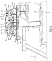
- each module 12 comprises a roller 37 integral with an arm 38, guided in a slide 39 formed around the periphery of the fixed ring 11 of the device 1.
- the roller 37 is able to cooperate with said deformation means and said cutting means of said module 12 for moving them between their respective inactive and active states, and vice versa, as it moves around the fixed ring gear 11 in the slide 39, specifically shaped to play such a cam role; that it will be described below.
- the arm 38 extending the roller 37 is integral with a bracket-shaped flange 40.
- the latter overlaps the base 13 so that a first leg 41 of the flange 40 extends in abutment against an upper end face 190 of each rod 19 in a plane perpendicular to the axes X1, X2 and a second tab 42 of the flange 40 extends in a plane parallel to the front face 27 of the base 13 opposite the outer face 43 of the movable upper blade 29.
- each of the connecting rods 44 comprises a first and a second parallel arm 45, 46, extending on either side of a central body 47, in opposite directions, perpendicular to the axes X1, X2.
- the first arm 45 is received in a housing 49 of the front face 27 of the base 13 and connected thereto by means of an axis engaged in a hole 48 of complementary shape that includes said housing 49.
- the second arm 46 is engaged to both in an "L" slot 50, having a section 51 of axis parallel to the axes X1, X2, formed in the second tab 42 of the flange 40 and in a slot 52 of axis perpendicular to the axes X1, X2 that has the movable upper blade 29.
- the slide 39 comprises first, second and third portions A, B, C, succeeding one another between the input zone 4 and the ejection zone 5, and configured so that the first portion A defines for each module 12 a path in which its roller 37 extends in a plane P1 in which it is located relative to the base 13 at a distance such that it acts neither on the rods 19, nor on the upper blade 29, which remain spaced from the corresponding folding matrices, and the lower blade 28 and are therefore placed in their inactive state while the two bands 2 are progressively routed.
- the second and third portions B, C of the slide 11 define for each module 12 paths in which the roller 37 extends in planes P2, P3, P4 below the plane P1 and is located relative to the base 13 at distances such that the deformation means and the cutting means are in their active state, which corresponds for the deformation means to different successive positions in which the rods 19 are progressively pushed through the orifices 21 and the passages 23 to allow first the deformation of the section of each strip 2, until they are completely traversed and lead to the ejection of each deformed strip section 2 to a compartment 70, 71 of the tray 7.
- the active state of the guillotine 26 is reached through of displacement in translation of the flange 40 under the effect of the change of plane of the roller 37, which displacement in translation causes that of the movable blade 29. It should be noted that this The latter moves linearly thanks to the symmetrical movement of the rods 44 which generate a support on either side of the blade 29. Moreover, a bias on the edge of the movable blade 29 gives the progressivity to the cut.
- the device 1 according to the invention makes it possible to achieve the objectives previously described.
- the punching is no longer performed by a mechanical system of reciprocating and actuated by a rotary cam, but by a carousel system along which several modules 12 move in being driven by a belt 15, allows to remove any mechanical stop noise.
- the system according to the invention makes it possible to double the production rate of the particles with respect to the devices of the prior art by less mobilizing the operators.
- the device according to the invention makes it possible to work with two rollers simultaneously during one hour of operation. without human intervention since a cell will stop the device automatically in case of full tank 7.
- the device 1 according to the invention makes it possible to eliminate jamming problems and is suitable for many types of materials, in particular for all types of paper.
- the system implemented based on a carousel 9, pulls the strips 2 of material, which eliminates any jams at the blades of the guillotine 26, observed with the machines of the state of the technique in which the paper web is pushed into the deformation mechanism by a wheel.
- the device 1 according to the invention also makes it possible to produce particles of different size and shape by replacing only the modules 12 with other modules 12 comprising folding matrices of different shape and size.
- the device 1 according to the invention is easy to maintain and requires replacement of less frequent wear parts.
Landscapes
- Perforating, Stamping-Out Or Severing By Means Other Than Cutting (AREA)
- Folding Of Thin Sheet-Like Materials, Special Discharging Devices, And Others (AREA)
Applications Claiming Priority (1)
| Application Number | Priority Date | Filing Date | Title |
|---|---|---|---|
| FR1757578A FR3070024A1 (fr) | 2017-08-08 | 2017-08-08 | Dispositif pour la fabrication d'un materiau de calage |
Publications (1)
| Publication Number | Publication Date |
|---|---|
| EP3441218A1 true EP3441218A1 (de) | 2019-02-13 |
Family
ID=59930603
Family Applications (1)
| Application Number | Title | Priority Date | Filing Date |
|---|---|---|---|
| EP18187261.5A Withdrawn EP3441218A1 (de) | 2017-08-08 | 2018-08-03 | Vorrichtung für die herstellung von verkeilungs-/füllmaterial |
Country Status (2)
| Country | Link |
|---|---|
| EP (1) | EP3441218A1 (de) |
| FR (1) | FR3070024A1 (de) |
Citations (2)
| Publication number | Priority date | Publication date | Assignee | Title |
|---|---|---|---|---|
| US20040108243A1 (en) * | 2002-12-04 | 2004-06-10 | Philippe Jeannin | Packaging material and method and device for producing the same |
| US20140274645A1 (en) * | 2013-03-15 | 2014-09-18 | Pregis Innovative Packaging Inc. | Tear-assist blade |
-
2017
- 2017-08-08 FR FR1757578A patent/FR3070024A1/fr not_active Ceased
-
2018
- 2018-08-03 EP EP18187261.5A patent/EP3441218A1/de not_active Withdrawn
Patent Citations (2)
| Publication number | Priority date | Publication date | Assignee | Title |
|---|---|---|---|---|
| US20040108243A1 (en) * | 2002-12-04 | 2004-06-10 | Philippe Jeannin | Packaging material and method and device for producing the same |
| US20140274645A1 (en) * | 2013-03-15 | 2014-09-18 | Pregis Innovative Packaging Inc. | Tear-assist blade |
Also Published As
| Publication number | Publication date |
|---|---|
| FR3070024A1 (fr) | 2019-02-15 |
Similar Documents
| Publication | Publication Date | Title |
|---|---|---|
| EP2337677B1 (de) | Transport- und biegevorrichtung für plattenelemente | |
| EP3038954B1 (de) | Verfahren zum transportieren und drehen flacher gegenstände | |
| EP2914523B1 (de) | Halterungsvorrichtung für ein plattes, blattförmiges element, das sich in einer bearbeitungsmaschine dreht | |
| EP2976279B1 (de) | Vorrichtung zum ausstossen eines flachen gegenstandes während der förderung | |
| EP2834178B1 (de) | Nonstop-gittervorrichtung für formmaschine | |
| EP2391501B1 (de) | Biegevorrichtung und -verfahren für biege-klebe-presse | |
| WO2012116781A1 (fr) | Dispositif de deroulage de bande pour machine d'impression par estampage | |
| EP2964556B1 (de) | Transportvorrichtung für ebene elemente | |
| EP2704973B1 (de) | Vorrichtung zum stapeln von papierbögen oder dergleichen | |
| WO2012034649A1 (fr) | Dispositif de guidage de bandes pour machine d'estampage | |
| EP2585258B1 (de) | Stützvorrichtung für eine arbeitsstation einer profilierungsmaschine | |
| CA2698423C (fr) | Dispositif de reception d'articles de courrier a haute capacite | |
| EP2196293B1 (de) | Schneidvorrichtung für Dekor für kegelförmige Träger und Vorrichtung zur Herstellung von kegelförmigen Trägern mit Dekoreinlage mit einer solchen Schneidvorrichtung | |
| WO2014154333A1 (fr) | Dispositif de pivotement d'objets plats | |
| EP3441218A1 (de) | Vorrichtung für die herstellung von verkeilungs-/füllmaterial | |
| EP2772457A1 (de) | Hilfsanlage zur Verpackung von Artikeln | |
| FR2937280A1 (fr) | Machine de traitement de documents a entrainement ameliore. | |
| FR2740762A1 (fr) | Dispositif d'empilement de produits en forme de cartes | |
| EP2481697B1 (de) | Stapelvorrichtung für Postartikelnbearbeitungsmaschine | |
| EP3331673B1 (de) | Vorrichtung für das schneiden von brot mit einer stützfläche für das brot, die einen schlitz für das messer aufweist | |
| FR2896722A1 (fr) | Dispositif de transport optimise pour machine de traitement de courrier | |
| FR2490457A1 (fr) | Machine a assembler les gaufrettes fourrees | |
| FR2725661A1 (fr) | Installation pour la production continue et a vitesse controlee d'articles compactes, et plus particulierement de briquettes de chauffage |
Legal Events
| Date | Code | Title | Description |
|---|---|---|---|
| PUAI | Public reference made under article 153(3) epc to a published international application that has entered the european phase |
Free format text: ORIGINAL CODE: 0009012 |
|
| AK | Designated contracting states |
Kind code of ref document: A1 Designated state(s): AL AT BE BG CH CY CZ DE DK EE ES FI FR GB GR HR HU IE IS IT LI LT LU LV MC MK MT NL NO PL PT RO RS SE SI SK SM TR |
|
| AX | Request for extension of the european patent |
Extension state: BA ME |
|
| STAA | Information on the status of an ep patent application or granted ep patent |
Free format text: STATUS: THE APPLICATION IS DEEMED TO BE WITHDRAWN |
|
| 18D | Application deemed to be withdrawn |
Effective date: 20190814 |