EP3441127B1 - Absorptionskolonne mit aussenliegendem wärmeaustauschkreislauf - Google Patents
Absorptionskolonne mit aussenliegendem wärmeaustauschkreislauf Download PDFInfo
- Publication number
- EP3441127B1 EP3441127B1 EP17400049.7A EP17400049A EP3441127B1 EP 3441127 B1 EP3441127 B1 EP 3441127B1 EP 17400049 A EP17400049 A EP 17400049A EP 3441127 B1 EP3441127 B1 EP 3441127B1
- Authority
- EP
- European Patent Office
- Prior art keywords
- absorption
- heat exchanger
- pipeline
- absorption liquid
- column according
- Prior art date
- Legal status (The legal status is an assumption and is not a legal conclusion. Google has not performed a legal analysis and makes no representation as to the accuracy of the status listed.)
- Active
Links
- 238000010521 absorption reaction Methods 0.000 title claims description 66
- 239000007788 liquid Substances 0.000 claims description 35
- 238000000034 method Methods 0.000 claims description 19
- OKKJLVBELUTLKV-UHFFFAOYSA-N Methanol Chemical compound OC OKKJLVBELUTLKV-UHFFFAOYSA-N 0.000 claims description 18
- UAOMVDZJSHZZME-UHFFFAOYSA-N diisopropylamine Chemical compound CC(C)NC(C)C UAOMVDZJSHZZME-UHFFFAOYSA-N 0.000 claims description 12
- XTHFKEDIFFGKHM-UHFFFAOYSA-N Dimethoxyethane Chemical compound COCCOC XTHFKEDIFFGKHM-UHFFFAOYSA-N 0.000 claims description 6
- SECXISVLQFMRJM-UHFFFAOYSA-N N-Methylpyrrolidone Chemical compound CN1CCCC1=O SECXISVLQFMRJM-UHFFFAOYSA-N 0.000 claims description 6
- 150000001412 amines Chemical class 0.000 claims description 4
- 238000001816 cooling Methods 0.000 claims description 4
- ZBCBWPMODOFKDW-UHFFFAOYSA-N diethanolamine Chemical compound OCCNCCO ZBCBWPMODOFKDW-UHFFFAOYSA-N 0.000 claims description 4
- HPNMFZURTQLUMO-UHFFFAOYSA-N diethylamine Chemical compound CCNCC HPNMFZURTQLUMO-UHFFFAOYSA-N 0.000 claims description 4
- 229940043279 diisopropylamine Drugs 0.000 claims description 4
- 238000010438 heat treatment Methods 0.000 claims description 4
- 230000005484 gravity Effects 0.000 claims description 3
- 239000000498 cooling water Substances 0.000 claims description 2
- 239000000945 filler Substances 0.000 claims description 2
- 239000000203 mixture Substances 0.000 claims description 2
- 238000000746 purification Methods 0.000 claims 2
- 230000002378 acidificating effect Effects 0.000 claims 1
- 239000002826 coolant Substances 0.000 claims 1
- 238000007599 discharging Methods 0.000 claims 1
- XLYOFNOQVPJJNP-UHFFFAOYSA-N water Substances O XLYOFNOQVPJJNP-UHFFFAOYSA-N 0.000 claims 1
- 239000007789 gas Substances 0.000 description 22
- 230000002745 absorbent Effects 0.000 description 16
- 239000002250 absorbent Substances 0.000 description 16
- 230000015572 biosynthetic process Effects 0.000 description 12
- 238000003786 synthesis reaction Methods 0.000 description 7
- 239000013590 bulk material Substances 0.000 description 6
- UGFAIRIUMAVXCW-UHFFFAOYSA-N Carbon monoxide Chemical compound [O+]#[C-] UGFAIRIUMAVXCW-UHFFFAOYSA-N 0.000 description 4
- 229910002091 carbon monoxide Inorganic materials 0.000 description 4
- JJWKPURADFRFRB-UHFFFAOYSA-N carbonyl sulfide Chemical compound O=C=S JJWKPURADFRFRB-UHFFFAOYSA-N 0.000 description 4
- 238000012856 packing Methods 0.000 description 3
- 238000012546 transfer Methods 0.000 description 3
- CURLTUGMZLYLDI-UHFFFAOYSA-N Carbon dioxide Chemical compound O=C=O CURLTUGMZLYLDI-UHFFFAOYSA-N 0.000 description 2
- 229910052739 hydrogen Inorganic materials 0.000 description 2
- 230000010354 integration Effects 0.000 description 2
- 238000010943 off-gassing Methods 0.000 description 2
- 239000003507 refrigerant Substances 0.000 description 2
- 239000000126 substance Substances 0.000 description 2
- RWSOTUBLDIXVET-UHFFFAOYSA-N Dihydrogen sulfide Chemical compound S RWSOTUBLDIXVET-UHFFFAOYSA-N 0.000 description 1
- 239000002202 Polyethylene glycol Substances 0.000 description 1
- 229910002092 carbon dioxide Inorganic materials 0.000 description 1
- 239000001569 carbon dioxide Substances 0.000 description 1
- AFYPFACVUDMOHA-UHFFFAOYSA-N chlorotrifluoromethane Chemical compound FC(F)(F)Cl AFYPFACVUDMOHA-UHFFFAOYSA-N 0.000 description 1
- 238000004140 cleaning Methods 0.000 description 1
- 239000003245 coal Substances 0.000 description 1
- 230000003247 decreasing effect Effects 0.000 description 1
- 230000006866 deterioration Effects 0.000 description 1
- 238000011161 development Methods 0.000 description 1
- PXBRQCKWGAHEHS-UHFFFAOYSA-N dichlorodifluoromethane Chemical compound FC(F)(Cl)Cl PXBRQCKWGAHEHS-UHFFFAOYSA-N 0.000 description 1
- 230000000694 effects Effects 0.000 description 1
- 239000000295 fuel oil Substances 0.000 description 1
- 238000002309 gasification Methods 0.000 description 1
- 239000001257 hydrogen Substances 0.000 description 1
- 125000004435 hydrogen atom Chemical class [H]* 0.000 description 1
- 238000012423 maintenance Methods 0.000 description 1
- 239000000463 material Substances 0.000 description 1
- 239000003921 oil Substances 0.000 description 1
- 230000003647 oxidation Effects 0.000 description 1
- 238000007254 oxidation reaction Methods 0.000 description 1
- 239000002006 petroleum coke Substances 0.000 description 1
- 229920001223 polyethylene glycol Polymers 0.000 description 1
- 238000011084 recovery Methods 0.000 description 1
- 230000001105 regulatory effect Effects 0.000 description 1
- 230000000630 rising effect Effects 0.000 description 1
- 239000002699 waste material Substances 0.000 description 1
Images
Classifications
-
- B—PERFORMING OPERATIONS; TRANSPORTING
- B01—PHYSICAL OR CHEMICAL PROCESSES OR APPARATUS IN GENERAL
- B01D—SEPARATION
- B01D53/00—Separation of gases or vapours; Recovering vapours of volatile solvents from gases; Chemical or biological purification of waste gases, e.g. engine exhaust gases, smoke, fumes, flue gases, aerosols
- B01D53/14—Separation of gases or vapours; Recovering vapours of volatile solvents from gases; Chemical or biological purification of waste gases, e.g. engine exhaust gases, smoke, fumes, flue gases, aerosols by absorption
- B01D53/18—Absorbing units; Liquid distributors therefor
-
- B—PERFORMING OPERATIONS; TRANSPORTING
- B01—PHYSICAL OR CHEMICAL PROCESSES OR APPARATUS IN GENERAL
- B01D—SEPARATION
- B01D53/00—Separation of gases or vapours; Recovering vapours of volatile solvents from gases; Chemical or biological purification of waste gases, e.g. engine exhaust gases, smoke, fumes, flue gases, aerosols
- B01D53/14—Separation of gases or vapours; Recovering vapours of volatile solvents from gases; Chemical or biological purification of waste gases, e.g. engine exhaust gases, smoke, fumes, flue gases, aerosols by absorption
- B01D53/1456—Removing acid components
- B01D53/1462—Removing mixtures of hydrogen sulfide and carbon dioxide
-
- C—CHEMISTRY; METALLURGY
- C01—INORGANIC CHEMISTRY
- C01B—NON-METALLIC ELEMENTS; COMPOUNDS THEREOF; METALLOIDS OR COMPOUNDS THEREOF NOT COVERED BY SUBCLASS C01C
- C01B3/00—Hydrogen; Gaseous mixtures containing hydrogen; Separation of hydrogen from mixtures containing it; Purification of hydrogen
- C01B3/50—Separation of hydrogen or hydrogen containing gases from gaseous mixtures, e.g. purification
- C01B3/52—Separation of hydrogen or hydrogen containing gases from gaseous mixtures, e.g. purification by contacting with liquids; Regeneration of used liquids
-
- C—CHEMISTRY; METALLURGY
- C10—PETROLEUM, GAS OR COKE INDUSTRIES; TECHNICAL GASES CONTAINING CARBON MONOXIDE; FUELS; LUBRICANTS; PEAT
- C10K—PURIFYING OR MODIFYING THE CHEMICAL COMPOSITION OF COMBUSTIBLE GASES CONTAINING CARBON MONOXIDE
- C10K1/00—Purifying combustible gases containing carbon monoxide
- C10K1/002—Removal of contaminants
- C10K1/003—Removal of contaminants of acid contaminants, e.g. acid gas removal
- C10K1/004—Sulfur containing contaminants, e.g. hydrogen sulfide
-
- C—CHEMISTRY; METALLURGY
- C10—PETROLEUM, GAS OR COKE INDUSTRIES; TECHNICAL GASES CONTAINING CARBON MONOXIDE; FUELS; LUBRICANTS; PEAT
- C10K—PURIFYING OR MODIFYING THE CHEMICAL COMPOSITION OF COMBUSTIBLE GASES CONTAINING CARBON MONOXIDE
- C10K1/00—Purifying combustible gases containing carbon monoxide
- C10K1/002—Removal of contaminants
- C10K1/003—Removal of contaminants of acid contaminants, e.g. acid gas removal
- C10K1/005—Carbon dioxide
-
- C—CHEMISTRY; METALLURGY
- C10—PETROLEUM, GAS OR COKE INDUSTRIES; TECHNICAL GASES CONTAINING CARBON MONOXIDE; FUELS; LUBRICANTS; PEAT
- C10K—PURIFYING OR MODIFYING THE CHEMICAL COMPOSITION OF COMBUSTIBLE GASES CONTAINING CARBON MONOXIDE
- C10K1/00—Purifying combustible gases containing carbon monoxide
- C10K1/08—Purifying combustible gases containing carbon monoxide by washing with liquids; Reviving the used wash liquors
- C10K1/10—Purifying combustible gases containing carbon monoxide by washing with liquids; Reviving the used wash liquors with aqueous liquids
- C10K1/12—Purifying combustible gases containing carbon monoxide by washing with liquids; Reviving the used wash liquors with aqueous liquids alkaline-reacting including the revival of the used wash liquors
- C10K1/14—Purifying combustible gases containing carbon monoxide by washing with liquids; Reviving the used wash liquors with aqueous liquids alkaline-reacting including the revival of the used wash liquors organic
-
- C—CHEMISTRY; METALLURGY
- C10—PETROLEUM, GAS OR COKE INDUSTRIES; TECHNICAL GASES CONTAINING CARBON MONOXIDE; FUELS; LUBRICANTS; PEAT
- C10K—PURIFYING OR MODIFYING THE CHEMICAL COMPOSITION OF COMBUSTIBLE GASES CONTAINING CARBON MONOXIDE
- C10K1/00—Purifying combustible gases containing carbon monoxide
- C10K1/08—Purifying combustible gases containing carbon monoxide by washing with liquids; Reviving the used wash liquors
- C10K1/16—Purifying combustible gases containing carbon monoxide by washing with liquids; Reviving the used wash liquors with non-aqueous liquids
-
- B—PERFORMING OPERATIONS; TRANSPORTING
- B01—PHYSICAL OR CHEMICAL PROCESSES OR APPARATUS IN GENERAL
- B01D—SEPARATION
- B01D2252/00—Absorbents, i.e. solvents and liquid materials for gas absorption
- B01D2252/20—Organic absorbents
- B01D2252/202—Alcohols or their derivatives
- B01D2252/2021—Methanol
-
- B—PERFORMING OPERATIONS; TRANSPORTING
- B01—PHYSICAL OR CHEMICAL PROCESSES OR APPARATUS IN GENERAL
- B01D—SEPARATION
- B01D2252/00—Absorbents, i.e. solvents and liquid materials for gas absorption
- B01D2252/20—Organic absorbents
- B01D2252/202—Alcohols or their derivatives
- B01D2252/2023—Glycols, diols or their derivatives
- B01D2252/2026—Polyethylene glycol, ethers or esters thereof, e.g. Selexol
-
- B—PERFORMING OPERATIONS; TRANSPORTING
- B01—PHYSICAL OR CHEMICAL PROCESSES OR APPARATUS IN GENERAL
- B01D—SEPARATION
- B01D2252/00—Absorbents, i.e. solvents and liquid materials for gas absorption
- B01D2252/20—Organic absorbents
- B01D2252/204—Amines
- B01D2252/2041—Diamines
-
- B—PERFORMING OPERATIONS; TRANSPORTING
- B01—PHYSICAL OR CHEMICAL PROCESSES OR APPARATUS IN GENERAL
- B01D—SEPARATION
- B01D2252/00—Absorbents, i.e. solvents and liquid materials for gas absorption
- B01D2252/20—Organic absorbents
- B01D2252/204—Amines
- B01D2252/20436—Cyclic amines
- B01D2252/20468—Cyclic amines containing a pyrrolidone-ring
-
- B—PERFORMING OPERATIONS; TRANSPORTING
- B01—PHYSICAL OR CHEMICAL PROCESSES OR APPARATUS IN GENERAL
- B01D—SEPARATION
- B01D2252/00—Absorbents, i.e. solvents and liquid materials for gas absorption
- B01D2252/20—Organic absorbents
- B01D2252/204—Amines
- B01D2252/20478—Alkanolamines
- B01D2252/20489—Alkanolamines with two or more hydroxyl groups
-
- B—PERFORMING OPERATIONS; TRANSPORTING
- B01—PHYSICAL OR CHEMICAL PROCESSES OR APPARATUS IN GENERAL
- B01D—SEPARATION
- B01D2252/00—Absorbents, i.e. solvents and liquid materials for gas absorption
- B01D2252/20—Organic absorbents
- B01D2252/205—Other organic compounds not covered by B01D2252/00 - B01D2252/20494
- B01D2252/2053—Other nitrogen compounds
-
- B—PERFORMING OPERATIONS; TRANSPORTING
- B01—PHYSICAL OR CHEMICAL PROCESSES OR APPARATUS IN GENERAL
- B01D—SEPARATION
- B01D2256/00—Main component in the product gas stream after treatment
- B01D2256/16—Hydrogen
-
- B—PERFORMING OPERATIONS; TRANSPORTING
- B01—PHYSICAL OR CHEMICAL PROCESSES OR APPARATUS IN GENERAL
- B01D—SEPARATION
- B01D2256/00—Main component in the product gas stream after treatment
- B01D2256/20—Carbon monoxide
-
- B—PERFORMING OPERATIONS; TRANSPORTING
- B01—PHYSICAL OR CHEMICAL PROCESSES OR APPARATUS IN GENERAL
- B01D—SEPARATION
- B01D2257/00—Components to be removed
- B01D2257/30—Sulfur compounds
- B01D2257/304—Hydrogen sulfide
-
- B—PERFORMING OPERATIONS; TRANSPORTING
- B01—PHYSICAL OR CHEMICAL PROCESSES OR APPARATUS IN GENERAL
- B01D—SEPARATION
- B01D2257/00—Components to be removed
- B01D2257/30—Sulfur compounds
- B01D2257/308—Carbonoxysulfide COS
-
- B—PERFORMING OPERATIONS; TRANSPORTING
- B01—PHYSICAL OR CHEMICAL PROCESSES OR APPARATUS IN GENERAL
- B01D—SEPARATION
- B01D2257/00—Components to be removed
- B01D2257/50—Carbon oxides
- B01D2257/504—Carbon dioxide
-
- B—PERFORMING OPERATIONS; TRANSPORTING
- B01—PHYSICAL OR CHEMICAL PROCESSES OR APPARATUS IN GENERAL
- B01D—SEPARATION
- B01D2259/00—Type of treatment
- B01D2259/65—Employing advanced heat integration, e.g. Pinch technology
- B01D2259/652—Employing advanced heat integration, e.g. Pinch technology using side coolers
-
- C—CHEMISTRY; METALLURGY
- C01—INORGANIC CHEMISTRY
- C01B—NON-METALLIC ELEMENTS; COMPOUNDS THEREOF; METALLOIDS OR COMPOUNDS THEREOF NOT COVERED BY SUBCLASS C01C
- C01B2203/00—Integrated processes for the production of hydrogen or synthesis gas
- C01B2203/04—Integrated processes for the production of hydrogen or synthesis gas containing a purification step for the hydrogen or the synthesis gas
- C01B2203/0415—Purification by absorption in liquids
-
- Y—GENERAL TAGGING OF NEW TECHNOLOGICAL DEVELOPMENTS; GENERAL TAGGING OF CROSS-SECTIONAL TECHNOLOGIES SPANNING OVER SEVERAL SECTIONS OF THE IPC; TECHNICAL SUBJECTS COVERED BY FORMER USPC CROSS-REFERENCE ART COLLECTIONS [XRACs] AND DIGESTS
- Y02—TECHNOLOGIES OR APPLICATIONS FOR MITIGATION OR ADAPTATION AGAINST CLIMATE CHANGE
- Y02A—TECHNOLOGIES FOR ADAPTATION TO CLIMATE CHANGE
- Y02A30/00—Adapting or protecting infrastructure or their operation
- Y02A30/27—Relating to heating, ventilation or air conditioning [HVAC] technologies
-
- Y—GENERAL TAGGING OF NEW TECHNOLOGICAL DEVELOPMENTS; GENERAL TAGGING OF CROSS-SECTIONAL TECHNOLOGIES SPANNING OVER SEVERAL SECTIONS OF THE IPC; TECHNICAL SUBJECTS COVERED BY FORMER USPC CROSS-REFERENCE ART COLLECTIONS [XRACs] AND DIGESTS
- Y02—TECHNOLOGIES OR APPLICATIONS FOR MITIGATION OR ADAPTATION AGAINST CLIMATE CHANGE
- Y02P—CLIMATE CHANGE MITIGATION TECHNOLOGIES IN THE PRODUCTION OR PROCESSING OF GOODS
- Y02P20/00—Technologies relating to chemical industry
- Y02P20/151—Reduction of greenhouse gas [GHG] emissions, e.g. CO2
Definitions
- the invention relates to an absorption column comprising at least one external heat exchange circuit for cooling or heating the absorption liquid, comprise one or more heat exchangers connected in series, the integration of the pipeline for removing the absorption liquid from the column above the integration of the pipeline in the direction of flow, first heat exchanger of the circuit.
- the invention also includes the use of an absorption column according to the invention for operating a system for carrying out an absorption process for separating accompanying gases from synthesis gas,
- Such absorption columns are e.g. used in plants using the rectisol process, and also in plants using the purisol and selexol processes.
- the Purisol and Selexol processes are described in Ullmann's Encyclopedia of Industrial Chemistry, 6th ed. Vol. 15, pp. 404-407 basically described.
- the Purisol process uses the organic absorbent N-methylpyrrolidone (NMP) and operates at ambient or slightly lower temperatures.
- NMP N-methylpyrrolidone
- the Selexol process uses polyethylene glycol dimethyl ether as an absorbent.
- the Rectisol process is described in Ullmann's Encyclopedia of Industrial Chemistry, 6th ed. Vol. 15, p. 399 ff , basically described.
- This method serves, as well as, for example, the Purisol method, for raw synthesis gas comprising carbon monoxide (CO) and hydrogen (H 2 ) consisting and produced, for. B. by partial oxidation of heavy oils, petroleum coke, waste materials or by coal or oil residue gasification, to clean off accompanying gases.
- the rectisol process uses cryogenic methanol as an absorbent, exploiting the property of the methanol that its absorbing capacity for the accompanying substances increases sharply with decreasing temperature, while it remains practically constant for CO and H 2 .
- the undesirable accompanying substances are mainly the accompanying gases carbonyl sulfide (COS), hydrogen sulfide (H 2 S) and carbon dioxide (CO 2 ).
- columns are used to carry out these absorption processes, in which the gas to be purified rising in them is brought into contact in countercurrent with the flowing down absorption liquid.
- the absorption liquid is heated by the heat released during absorption, which reduces its absorption capacity.
- the absorption liquid is therefore discharged from the column at a suitable point, passed over a heat exchanger and reintroduced into the column.
- the liquid is transported solely by using the height difference between the removal point and the re-feeding point in the column, because every input of mechanical energy, eg. B. by pumps, would lead to increased bubble formation and thus to partial outgassing of the gas already absorbed.
- Corresponding absorption columns from the prior art are in the documents DE102015101415 . EP3132840 . US4324567 . US2014190350 and GB1071929 disclosed.
- the absorption liquid flows through the cooler from bottom to top.
- the supply line to the cooler has to pass through a deepest reversal point, often also called a line sack.
- violent flow turbulence can lead to increased bubble development due to outgassing in the absorption liquid and, especially if the down pipe is not completely filled , gas can be entrained by the liquid falling down the slope. While larger bubbles rise against the flow direction of the liquid in the line and get into the column, smaller bubbles are carried away by the flow through the line bag, get into the heat exchanger and impair the heat transfer there.
- the object of the invention is therefore to provide a cheaper, technically simple and reliable solution.
- the object is achieved by an absorption column according to claim 1.
- Absorption columns comprising at least one external heat exchange circuit for cooling or heating the absorption liquid, comprise one or more heat exchangers connected in series, the connection of the pipeline for removing the absorption liquid from the column being above the connection of the pipeline in the first heat exchanger in the flow direction, characterized in that a bulk material bed is installed in the course of this pipeline.
- the bulk material bed prevents the absorption liquid from shooting down the slope of the supply line to the cooler like a waterfall during part-load operation, which would result in severe bubble formation and entrainment of gas.
- the bulk material bed slows down the flow rate and thus reduces the entry of mechanical energy into the absorption liquid and thus reduces the formation of bubbles.
- bubbles that are formed remain on the surface of the packing, where they form larger bubbles, which rise up against the liquid flow in the circuit line and reach the column.
- a preferred embodiment of the absorption column is characterized in that the bulk bed consists of packing elements. This primarily means random packing, such as those used for mass transfer in columns. These fillers are available in numerous designs, so that the right shape, the right material and the right size can be found from a large selection.
- a further preferred embodiment of the absorption column is characterized in that the pipeline for supplying the absorption liquid into the heat exchanger or the heat exchangers in each case on its underside and that for removal on its top.
- the absorption liquid flows through the heat exchanger (s) from bottom to top, as a result of which there are fewer gas bubbles in the liquid and the contact between the liquid and the heat exchanger surface is less disturbed by bubbles.
- a further preferred embodiment of the absorption column is characterized in that the removal and the recovery point of the absorption liquid from the column and the bulk material bed and the heat exchanger (s) are arranged in relation to one another in such a way that the flow of the absorption liquid through the heat exchange circuit only through the Gravity is driven. By dispensing with pumps, less mechanical energy is transferred to the liquid, which would otherwise promote blistering.
- a further preferred embodiment of the absorption column is characterized in that the heat exchangers are each connected to a refrigerant, cold or cooling water circuit or are connected as economizers to an internal absorption medium stream.
- the most cost-effective heat transfer medium or a combination of different ones by connecting several heat exchangers in series can be used in a specific individual case.
- An economizer is a heat exchanger that brings two process streams, in this case two absorbent streams, into heat exchange with one another.
- the invention also includes the use of an absorption column according to the invention for operating a plant for carrying out a method for separating accompanying gases from synthesis gas, such as e.g. the rectisol, purisol or selexol process.
- the invention includes the use of an absorption column according to the invention for operating a gas cleaning process that contains mixtures as the absorption medium between methanol and N-methylpyrrolidone, N-methylpyrrolidone and an amine-containing absorbent (especially diethanolamine, diisopropylamine, diethylamine) or methanol and an amine-containing absorbent (especially diethanolamine, diisopropylamine or diethylamine).
- an absorption column according to the invention for operating a gas cleaning process that contains mixtures as the absorption medium between methanol and N-methylpyrrolidone, N-methylpyrrolidone and an amine-containing absorbent (especially diethanolamine, diisopropylamine, diethylamine) or methanol and an amine-containing absorbent (especially diethanolamine, diisopropylamine or diethylamine).
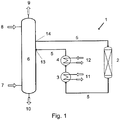
- FIG. 1 shows an example of an absorption column according to the invention with an external heat exchange circuit.
- the external heat exchange circuit 1 comprises the bulk material bed 2, the heat exchangers 3 and 4 and the circuit line 5. Furthermore, the drawing shows an absorption column 6. Synthesis gas 7 is washed in this column 6 by a liquid absorption medium 8. The synthesis gas 9 treated in this way and the loaded absorbent 10 are discharged from the column 6 for the respective further treatment, not shown. The absorbent 8, after it has been loaded in the upper part of the column 6 and the resulting heat of absorption has been heated, is discharged from the column 6 and fed to the bulk material bed 2 through the circulation line 5.
- the bulk bed 2 can e.g. B. consist of a bed of Pall rings, Raschig rings or inert bodies.
- the absorption liquid flows through the heat exchangers 3 and 4, likewise in order to avoid turbulence as far as possible, from bottom to top.
- the heat exchanger 3 is used as an economizer and exchanges the heat of the absorbent flowing through the circuit line 5 with the heat of another, internal absorbent stream 11.
- the heat exchanger 4 works in this example as a cooler and is operated with a refrigerant 12 cooled in a refrigerant system, not shown.
- the opening 13 for returning the absorbent into the column 6 through the circulation line 5 binds so far below the opening for removal 14 into the column 6 that the absorption liquid can be transported through the heat exchange circuit solely by gravity.
- the invention provides an inexpensive solution for keeping the formation of bubbles low and thus for maintaining a good heat exchange. Heat exchange circuit of an absorption column.
- the invention is therefore commercially applicable.
Description
- Die Erfindung betrifft eine Absorptionskolonne, umfassend mindestens einen außenliegenden Wärmeaustauschkreislauf zur Kühlung oder Erwärmung der Absorptionsflüssigkeit, umfassen einen oder mehrere in Reihe geschaltete Wärmeaustauscher, wobei die Einbindung der Rohrleitung zur Entnahme der Absorptionsflüssigkeit aus der Kolonne oberhalb der Einbindung der Rohrleitung in den, in Fließrichtung, ersten Wärmeaustauschers des Kreislaufs liegt.
- Zur Erfindung gehört auch die Verwendung einer erfindungsgemäßen Absorptionskolonne zum Betreiben einer Anlage zur Durchführung eines Absorptionsverfahrens zur Abtrennen von Begleitgasen aus Synthesegas,
- Derartige Absorptionskolonnen werden z.B. in nach dem Rectisol-Verfahren arbeitenden Anlagen verwendet, und auch in Anlagen des Purisol- und des Selexol-Verfahrens.
- Das Purisol- und das Selexol-Verfahren werden in Ullmann's Encyclopedia of Industrial Chemistry, 6. Aufl. Bd. 15, S. 404 - 407 grundsätzlich beschrieben. Das Purisol-Verfahren verwendet das organische Absorptionsmittel N-Methylpyrrolidon (NMP) und wird bei Umgebungs- oder leicht darunter liegenden Temperaturen betrieben. Das Selexol-Verfahren verwendet Polyethylenglykoldimethylether als Absorptionsmittel.
- Das Rectisol Verfahren wird in Ullmann's Encyclopedia of Industrial Chemistry, 6. Aufl. Bd. 15, S. 399 ff. grundsätzlich beschrieben. Dieses Verfahren dient, ebenso wie beispielsweise das Purisol-Verfahren, dazu, Rohsynthesegas, umfassend Kohlenmonoxid (CO) und Wasserstoff (H2) bestehend und hergestellt z. B. durch partielle Oxidation von Schwerölen, Petrolkoks, Abfallstoffen oder durch Kohle- bzw. Ölrückstandsvergasung, von Begleitgasen zu reinigen. Das Rectisol-Verfahren verwendet als Absorptionsmittel tiefkaltes Methanol, wobei die Eigenschaft des Methanols ausgenutzt wird, dass seine Absorptionsfähigkeit für die Begleitstoffe mit abnehmender Temperatur stark zunimmt, während sie für CO und H2 praktisch konstant bleibt. Bei den unerwünschten Begleitstoffen handelt es sich hauptsächlich um die Begleitgase Carbonylsulfid (COS), Schwefelwasserstoff (H2S) und Kohlendioxid (CO2).
- Zur Durchführung dieser Absorptionsverfahren werden in vielen Fällen Kolonnen verwendet, in denen das darin aufsteigende, zu reinigende Gas im Gegenstrom mit der herabfließenden Absorptionsflüssigkeit in Kontakt gebracht wird. Die Absorptionsflüssigkeit wird dabei durch die bei der Absorption freigesetzten Wärme erwärmt, wodurch ihre Absorptionsfähigkeit sinkt.
- Es gibt auch Anwendungsfälle, in denen ein Absenken der Absorptionsfähigkeit erwünscht ist und darum die Absorptionsflüssigkeit erwärmt wird. Die ist z. B. der Fall, wenn durch Strippen bereits absorbiertes Gas aus der Absorptionsflüssigkeit abgetrennt werden soll.
- Zur Kühlung oder Erwärmung wird die Absorptionsflüssigkeit darum an geeigneter Stelle aus der Kolonne ausgeleitet, über einen Wärmeaustauscher geführt und wieder in die Kolonne eingeleitet. Dabei erfolgt der Transport der Flüssigkeit allein unter Ausnutzung des Höhenunterschieds zwischen der Entnahmestelle und der Wiedereinspeisungsstelle in die Kolonne, denn jeder Eintrag von mechanischer Energie, z. B. durch Pumpen, würde zu erhöhter Blasenbildung und damit zur teilweisen Ausgasung des bereits absorbierten Gases führen. Entsprechende Absorptionskolonnen aus dem Stand der Technik sind in den Dokumenten
DE102015101415 ,EP3132840 ,US4324567 ,US2014190350 undGB1071929 - Um einen möglichst guten Kontakt zwischen der Absorptionsflüssigkeit und der Wärmeaustauschfläche des Kühlers zu erhalten, wird der Kühler von der Absorptionsflüssigkeit von unten nach oben durchflossen. Dies führt aber dazu, dass die Zuführleitung zum Kühler einen tiefst gelegenen Umkehrpunkt, häufig auch Leitungssack genannt, durchlaufen muss. Im in Fließrichtung vor dem Tiefpunkt des Leitungssacks gelegenen, mit Gefälle verlegten Leitungsteil, kann es, insbesondere wenn die Absorptionsanlage mit Teillast betrieben wird, durch heftige Strömungsturbulenzen zu einer erhöhten Blasenentwicklung durch Ausgasung in der Absorptionsflüssigkeit kommen und, besonders wenn die Fallleitung nicht ganz gefüllt ist, kann durch die die Gefällstrecke herabstürzende Flüssigkeit Gas mitgerissen werden. Während größere Blasen entgegen der Strömungsrichtung der Flüssigkeit in der Leitung aufsteigen und in die Kolonne gelangen, werden kleinere Blasen von der Strömung durch den Leitungssack mitgerissen, gelangen in den Wärmeaustauscher und beeinträchtigen dort den Wärmeübergang.
- Bisher wird diesem Problem dadurch begegnet, dass der Füllstand im mit Gefälle verlegten Teil der Zuführleitung mit einem in der Rückführleitung, zwischen dem Kühler und der Kolonne gelegenen Ventil geregelt wird. Damit soll erreicht werden, dass die Rohrleitung im Gefälleteil stets gefüllt ist und so die Turbulenzen gering gehalten werden. Nachteilig an dieser Lösung sind aber die hohen Investitions- und Instandhaltungskosten.
- Die Aufgabe der Erfindung ist es daher, eine preiswertere, technisch einfache und zuverlässige Lösung zur Verfügung zu stellen.
- Die Aufgabe wird durch eine Absorptionskolonne gemäß Anspruch 1 gelöst.
- Absorptionskolonne, umfassend mindestens einem außenliegenden Wärmeaustauschkreislauf zur Kühlung oder Erwärmung der Absorptionsflüssigkeit, umfassen einen oder mehrere in Reihe geschaltete Wärmeaustauscher, wobei die Einbindung der Rohrleitung zur Entnahme der Absorptionsflüssigkeit aus der Kolonne oberhalb der Einbindung der Rohrleitung in den, in Fließrichtung, ersten Wärmetauscher liegt, dadurch gekennzeichnet, dass im Verlauf dieser Rohrleitung ein Schüttgutbett installiert ist.
- Das Schüttgutbett verhindert, dass die Absorptionsflüssigkeit bei Teillastbetrieb wasserfallartig die Gefällstrecke der Zuführleitung zum Kühler hinunterschießt, wodurch es zu starker Blasenbildung und zum Mitreißen von Gas kommen würde. Das Schüttgutbett verlangsamt die Fließgeschwindigkeit und verringert damit den Eintrag an mechanischer Energie in die Absorptionsflüssigkeit und verringert damit die Blasenbildung. Dennoch gebildete Blasen bleiben auf der Oberfläche der Füllkörper hängen, schließen sich dort zu größeren Blasen zusammen, die entgegen der Flüssigkeitsströmung in der Kreislaufleitung aufsteigen und in die Kolonne gelangen. Durch diese Effekte wird die Menge an Blasen, die in den Wärmeaustauscher mitgerissenen werden, verringert. Auf diese Weise wird einer Verschlechterung des Wärmeaustauschs im Wärmeaustauscher entgegengewirkt.
- Eine bevorzugte Ausgestaltung der Absorptionskolonne ist dadurch gekennzeichnet, dass das Schüttgutbett aus Füllkörpern besteht. Damit sind in erster Linie regellose Füllkörper gemeint, wie sie für den Stoffaustausch in Kolonnen eingesetzt werden. Diese Füllkörper sind in zahlreichen Ausführungen erhältlich, sodass aus einer großen Auswahl die passende Form, der passende Werkstoff und die passende Größe gefunden werden kann.
- Eine weitere bevorzugte Ausgestaltung der Absorptionskolonne ist dadurch gekennzeichnet, dass die Rohrleitung zur Zufuhr der Absorptionsflüssigkeit in den oder die Wärmeaustauscher jeweils an dessen Unterseite und die zur Abfuhr an dessen Oberseite einbindet. Auf diese Weise durchströmt die Absorptionsflüssigkeit den bzw. die Wärmeaustauscher von unten nach oben, wodurch weniger Gasblasen in der Flüssigkeit vorhanden sind und den Kontakt zwischen der Flüssigkeit und der Wärmetauscherfläche weniger durch Blasen gestört ist.
- Eine weitere bevorzugte Ausgestaltung der Absorptionskolonne ist dadurch gekennzeichnet, dass die Entnahme- und die Rückspeisestelle der Absorptionsflüssigkeit aus der Kolonne und das Schüttgutbett und der oder die Wärmetauscher bezüglich der Höhe so zu einander angeordnet sind, dass der Fluss der Absorptionsflüssigkeit durch den Wärmeaustauschkreislauf allein durch die Schwerkraft angetrieben wird. Durch den Verzicht auf Pumpen wird weniger mechanische Energie auf die Flüssigkeit übertragen, die ansonsten Blasenbildung begünstigen würde.
- Eine weitere bevorzugte Ausgestaltung der Absorptionskolonne ist dadurch gekennzeichnet, dass die Wärmeaustauscher jeweils an einen Kältemittel-, Kalt- oder Kühlwasserkreislauf angeschlossen sind oder als Economiser mit einem verfahrensinternen Absorptionsmittelstrom verbunden sind. So kann im konkreten Einzelfall das kostengünstigste Wärmeträgermedium oder eine Kombination aus verschiedenen, indem mehrere Wärmeaustauscher hintereinander geschaltet werden, verwendet werden. Als Economiser wird ein Wärmeaustauscher bezeichnet, der zwei Prozessströme, in diesem Fall zwei Absorptionsmittelströme, miteinander in Wärmeaustausch bringt.
- Zur Erfindung gehört auch die Verwendung einer erfindungsgemäßen Absorptionskolonne zum Betreiben einer Anlage zur Durchführung eines Verfahrens zur Abtrennen von Begleitgasen aus Synthesegas, wie z.B. dem Rectisol-, Purisol- oder Selexol-Verfahren.
- Weiterhin gehört zur Erfindung die Verwendung einer erfindungsgemäßen Absorptionskolonne zum Betreiben eines Gasreinigungsverfahrens, dass als Absorptionsmittel Mischungen zwischen Methanol und N-Methylpyrrolidon, N-Methylpyrrolidon und einem aminhaltigen Absorptionsmittel (besonders Diethanolamin, Diisopropylamin, Diethylamin) oder Methanol und einem aminhaltigen Absorptionsmittel (besonders Diethanolamin, Diisopropylamin oder Diethylamin) verwendet.
- Weitere Merkmale, Vorteile und Anwendungsmöglichkeiten der Erfindung ergeben sich auch aus der nachfolgenden Beschreibung eines Ausführungsbeispiels und der Zeichnung. Dabei bilden alle beschriebenen und/oder bildlich dargestellten Merkmale für sich oder in beliebiger Kombination den Gegenstand der Erfindung, unabhängig von ihrer Zusammenfassung in den Ansprüchen oder deren Rückbeziehung.
- Die einzige Zeichnung,
Fig. 1 zeigt beispielhaft eine erfindungsgemäße Absorptionskolonne mit außenliegendem Wärmeaustauschkreislauf. - Anhand der Zeichnung soll beispielhaft der Aufbau einer erfindungsgemäße Absorptionskolonne mit außenliegendem Wärmeaustauschkreislauf erläutert werden.
- Der außenliegende Wärmeaustauschkreislauf 1 umfasst das Schüttgutbett 2, die Wärmeaustauscher 3 und 4 und die Kreislaufleitung 5. Weiterhin zeigt die Zeichnung eine Absorptionskolonne 6. In diese Kolonne 6 wird Synthesegas 7 von einem flüssigen Absorptionsmittel 8 gewaschen. Das so behandelte Synthesegas 9 und das beladene Absorptionsmittel 10 werden aus der Kolonne 6 zur jeweils weiteren, nicht dargestellten Behandlung ausgeleitet. Das Absorptionsmittel 8 wird, nachdem es im oberen Teil der Kolonne 6 beladen und die dabei entstandene Absorptionswärme erwärmt wurde, aus der Kolonne 6 ausgeleitet und durch die Kreislaufleitung 5 dem Schüttgutbett 2 zugeführt. Das Schüttgutbett 2 kann z. B. aus einer Schüttung aus Pall-Ringen, Raschig-Ringen oder Inertkörpern bestehen. Es hat die Aufgabe, Turbulenzen in der abwärts gerichteten Strömung zu dämpfen, um die Bildung von Gasblasen und das Mitreißen von Gas möglichst zu unterbinden. Anderenfalls würde das mitgerissene Gas bzw. die Gasblasen von der Strömung in die Wärmeaustauscher 3 und 4 mitgeführt und dort den Kontakt zwischen der Absorptionsflüssigkeit und der Wärmeaustauschfläche verschlechtern.
- Die Absorptionsflüssigkeit durchströmt die Wärmeaustauscher 3 und 4, ebenfalls um Turbulenzen möglichst zu vermeiden, von unten nach oben. Der Wärmeaustauscher 3 wird in diesem Beispiel als Economiser eingesetzt und tauscht die Wärme des durch die Kreislaufleitung 5 strömenden Absorptionsmittels gegen die Wärme eines anderen, verfahrensinternen Absorptionsmittelstroms 11 aus. Der Wärmeaustauscher 4 arbeitet in diesem Beispiel als Kühler und wird mit einem in einer nicht dargestellten Kältemittelanlage gekühltem Kältemittel 12 betrieben.
- Die Öffnung 13 zur Rückführung des Absorptionsmittels in die Kolonne 6 durch die Kreislaufleitung 5 bindet soweit unterhalb der Öffnung zur Entnahme 14 in die Kolonne 6 ein, dass der Transport der Absorptionsflüssigkeit durch den Wärmeaustauschkreislauf allein durch die Schwerkraft erfolgen kann.
- Die Erfindung liefert eine kostengünstige Lösung zur Geringhaltung der Blasenbildung und damit der Aufrechterhaltung eines guten Wärmeaustauschs Wärmeaustauschkreislauf einer Absorptionskolonne. Damit ist die Erfindung gewerbsmäßig anwendbar.
-
- 1
- Wärmeaustauschkreislauf
- 2
- Schüttgutbett
- 3
- Wärmeaustauscher (z. B. Economiser)
- 4
- Wärmeaustauscher (z. B. Kühler)
- 5
- Kreislaufleitung
- 6
- Absorptionskolonne
- 7
- Synthesegas
- 8
- Absorptionsmittel
- 9
- Synthesegas, behandelt
- 10
- Beladenes Absorptionsmittel
- 11
- Verfahrensinterner Absorptionsmittelstrom
- 12
- Kältemittel
- 13
- Öffnung zur Rückführung des Absorptionsmittels
- 14
- Öffnung zur Entnahme des Absorptionsmittels
Claims (7)
- Absorptionskolonne (6), umfassend mindestens einen außenliegenden Wärmeaustauschkreislauf (1) zur Kühlung oder Erwärmung der Absorptionsflüssigkeit, umfassend einen oder mehrere in Reihe geschaltete Wärmetauscher (3/4), wobei die Einbindung der Rohrleitung (5) zur Entnahme der Absorptionsflüssigkeit aus der Kolonne (6) oberhalb der Einbindung der Rohrleitung (5) in den, in Fließrichtung, ersten Wärmetauscher (3) liegt, dadurch gekennzeichnet, dass im Verlauf dieser Rohrleitung ein Schüttgutbett (2) installiert ist.
- Absorptionskolonne gemäß. Anspruch 1, dadurch gekennzeichnet, dass das Schüttgutbett (2) aus Füllkörpern besteht.
- Absorptionskolonne gemäß Anspruch 1 oder 2, dadurch gekennzeichnet, dass die Rohrleitung (5) zur Zufuhr der Absorptionsflüssigkeit in den mindestens einen Wärmeaustauscher (3) an dessen Unterseite und die Rohrleitung zur Abfuhr der Absorptionsflüssigkeit aus dem mindestens einen Wärmeaustauscher (3) an dessen Oberseite einbindet.
- Absorptionskolonne gemäß einem der vorhergehenden Ansprüche, dadurch gekennzeichnet, dass die Entnahmestelle (14) und die Rückspeisestelle (13) der Absorptionsflüssigkeit aus der Kolonne (6) und das Schüttgutbett (2) und der mindestens eine Wärmetauscher (3/4) bezüglich der Höhe so zueinander angeordnet sind, dass der Fluss der Absorptionsflüssigkeit durch den Wärmeaustauschkreislauf (1) allein durch die Schwerkraft angetrieben wird.
- Absorptionskolonne gemäß einem der vorhergehenden Ansprüche, dadurch gekennzeichnet, dass die Wärmeaustauscher (3/4) jeweils an einen Kältemittel-, Kalt- oder Kühlwasserkreislauf (12) angeschlossen sind oder als Economiser mit einem verfahrensinternen Absorptionsmittelstrom (11) verbunden sind.
- Verwendung einer Absorptionskolonne gemäß einem der vorhergehenden Ansprüche in einer Gasreinigungsanlage zur Abscheidung acider Gaskomponenten, ins-AIR LIQUIDE-Aktenzeichen 2016P00207 besondere einer Anlage zum Betreiben des Rectisol-, des Purisol- oder des Selexol-Verfahrens.
- Verwendung einer Absorptionskolonne gemäß einem der Ansprüche 1 bis 5 zum Betreiben eines Gasreinigungsverfahrens, das als Absorptionsmittel Mischungen zwischen Methanol und N-Methylpyrrolidon, N-Methylpyrrolidon und einem aminhaltigen Absorptionsmittel (besonders Diethanolamin, Diisopropylamin, Diethylamin) oder Methanol und einem aminhaltigen Absorptionsmittel (besonders Diethanolamin, Diisopropylamin, Diethylamin) verwendet.
Priority Applications (5)
| Application Number | Priority Date | Filing Date | Title |
|---|---|---|---|
| EP17400049.7A EP3441127B1 (de) | 2017-08-07 | 2017-08-07 | Absorptionskolonne mit aussenliegendem wärmeaustauschkreislauf |
| PCT/EP2018/025209 WO2019029846A1 (en) | 2017-08-07 | 2018-08-02 | ABSORPTION COLUMN HAVING EXTERNAL HEAT EXCHANGE CIRCUIT |
| US16/637,033 US11628392B2 (en) | 2017-08-07 | 2018-08-02 | Absorption column having external heat exchange circuit |
| CN201821269121.6U CN209204980U (zh) | 2017-08-07 | 2018-08-07 | 吸收塔 |
| CN201810893258.7A CN109381969B (zh) | 2017-08-07 | 2018-08-07 | 具有外部热交换回路的吸收塔 |
Applications Claiming Priority (1)
| Application Number | Priority Date | Filing Date | Title |
|---|---|---|---|
| EP17400049.7A EP3441127B1 (de) | 2017-08-07 | 2017-08-07 | Absorptionskolonne mit aussenliegendem wärmeaustauschkreislauf |
Publications (2)
| Publication Number | Publication Date |
|---|---|
| EP3441127A1 EP3441127A1 (de) | 2019-02-13 |
| EP3441127B1 true EP3441127B1 (de) | 2020-02-12 |
Family
ID=59997294
Family Applications (1)
| Application Number | Title | Priority Date | Filing Date |
|---|---|---|---|
| EP17400049.7A Active EP3441127B1 (de) | 2017-08-07 | 2017-08-07 | Absorptionskolonne mit aussenliegendem wärmeaustauschkreislauf |
Country Status (4)
| Country | Link |
|---|---|
| US (1) | US11628392B2 (de) |
| EP (1) | EP3441127B1 (de) |
| CN (2) | CN209204980U (de) |
| WO (1) | WO2019029846A1 (de) |
Families Citing this family (1)
| Publication number | Priority date | Publication date | Assignee | Title |
|---|---|---|---|---|
| EP3441127B1 (de) * | 2017-08-07 | 2020-02-12 | L'air Liquide, Société Anonyme Pour L'Étude Et L'exploitation Des Procédés Georges Claude | Absorptionskolonne mit aussenliegendem wärmeaustauschkreislauf |
Family Cites Families (10)
| Publication number | Priority date | Publication date | Assignee | Title |
|---|---|---|---|---|
| US3390058A (en) * | 1964-06-08 | 1968-06-25 | Toyo Koatsu Ind Inc | Plural stage pressure distillation of urea synthesis effluent with liquified gas addition |
| DE2856078A1 (de) * | 1978-12-23 | 1980-07-10 | Linde Ag | Verfahren zum abtrennen und gewinnen gasfoermiger komponenten aus einem gasgemisch durch physikalische waesche |
| US20070221065A1 (en) * | 2006-03-23 | 2007-09-27 | Adisorn Aroonwilas | Heat recovery gas absorption process |
| DE102011107814A1 (de) * | 2011-07-01 | 2013-01-03 | Linde Aktiengesellschaft | Verfahren und Vorrichtung zur Gewinnung von Gasprodukten |
| US9314732B2 (en) | 2013-01-09 | 2016-04-19 | Fluor Technologies Corporation | Systems and methods for reducing the energy requirements of a carbon dioxide capture plant |
| CN203803331U (zh) * | 2014-01-16 | 2014-09-03 | 中石化宁波工程有限公司 | 一种配套低温甲醇洗工艺的h2s浓缩装置 |
| EP3094399B8 (de) * | 2014-01-16 | 2020-03-04 | Sistemi Energetici S.p.A. | Neuartige verbindungen zur erfassung von kohlendioxid aus gasgemischen und anschliessender freisetzung |
| DE102015101415A1 (de) * | 2015-01-30 | 2016-08-04 | L'Air Liquide, Société Anonyme pour l'Etude et l'Exploitation des Procédés Georges Claude | Verfahren und Anlage zur Reinigung von Rohgasen mittels physikalischer Gaswäsche |
| EP3132840B1 (de) * | 2015-08-19 | 2020-02-19 | Siemens Aktiengesellschaft | Verfahren und vorrichtung zur abtrennung von gasförmigen schadstoffen aus einem gasstrom |
| EP3441127B1 (de) * | 2017-08-07 | 2020-02-12 | L'air Liquide, Société Anonyme Pour L'Étude Et L'exploitation Des Procédés Georges Claude | Absorptionskolonne mit aussenliegendem wärmeaustauschkreislauf |
-
2017
- 2017-08-07 EP EP17400049.7A patent/EP3441127B1/de active Active
-
2018
- 2018-08-02 WO PCT/EP2018/025209 patent/WO2019029846A1/en active Application Filing
- 2018-08-02 US US16/637,033 patent/US11628392B2/en active Active
- 2018-08-07 CN CN201821269121.6U patent/CN209204980U/zh not_active Withdrawn - After Issue
- 2018-08-07 CN CN201810893258.7A patent/CN109381969B/zh active Active
Non-Patent Citations (1)
| Title |
|---|
| None * |
Also Published As
| Publication number | Publication date |
|---|---|
| CN109381969A (zh) | 2019-02-26 |
| US11628392B2 (en) | 2023-04-18 |
| CN109381969B (zh) | 2022-03-01 |
| CN209204980U (zh) | 2019-08-06 |
| EP3441127A1 (de) | 2019-02-13 |
| WO2019029846A1 (en) | 2019-02-14 |
| US20200238213A1 (en) | 2020-07-30 |
Similar Documents
| Publication | Publication Date | Title |
|---|---|---|
| EP0606573A1 (de) | Verfahren zur Kühlung und Reinigung von ultrafeine Partikel enthaltendem Gas, insbesondere Gichtgas oder Generatorgas und Vorrichtung zu seiner Durchführung | |
| DE3144863C2 (de) | Wärmetauscher mit Fließbett | |
| WO2010139377A1 (de) | Wäscherturm und zugehörige rauchgasreinigungsvorrichtung | |
| DE3107156A1 (de) | Anlage zur erzeugung von gasfoermigen produkten | |
| EP2612098A2 (de) | Wärmespeichersystem | |
| EP3441127B1 (de) | Absorptionskolonne mit aussenliegendem wärmeaustauschkreislauf | |
| DE102007009759A1 (de) | Verfahren und Vorrichtung zur Aufteilung eines Feststoffstromes | |
| DE3214618A1 (de) | Verfahren sowie vorrichtung zur kuehlung und reinigung eines heissen gases | |
| EP3501622A1 (de) | Absorberkolonne und verfahren zur reinigung von rohsynthesegas | |
| DE3123683A1 (de) | Verfahren zum abloeschen von koks und waschen der dabei entstehenden gase | |
| DE102008057264A1 (de) | Vorrichtung zum Abscheiden von Flüssigkeiten aus Gasströmen sowie Verfahren zur Entfeuchtung und/oder Entstaubung von Rauchgas unter Verwendung wenigstens einer Vorrichtung zum Abscheiden von Flüssigkeiten aus Gasströmen | |
| DE102005037469B4 (de) | Vorrichtung und Verfahren zur Abscheidung von anorganischen Feststoffen aus einer wässrigen Lösung | |
| AT407645B (de) | Vorrichtung zur erzeugung von eisenschwamm | |
| WO2009092569A2 (de) | Verfahren und anlage zur entfernung insbesondere bei der synthesegas-gewinnung anfallenden schlacken aus einem schlackebad-behälter | |
| DE202017107744U1 (de) | Anlage zur Abtrennung von Begleitgasen aus einem Rohsynthesegas | |
| EP3666364B1 (de) | Verfahren und vorrichtung zur regenerierung eines beladenen waschmittels aus einer gaswäsche | |
| DE102016010515A1 (de) | Verfahren und Vorrichtung zur effektiven Strippung von teilbeladenem Waschmittel bei physikalischen Gaswäschen | |
| DE3205720C2 (de) | ||
| DE102008035604A1 (de) | Vorrichtung und Verfahren zur Entgasung von Stäuben | |
| EP3441122A1 (de) | Kolonne zum strippen und reabsorbieren | |
| EP2526332B1 (de) | Vorrichtung zum befeuchten eines schüttguts | |
| DE202018102916U1 (de) | Absorptionskolonne zur Abtrennung von Kohlendioxid aus einem Synthesegas | |
| DE19518191C2 (de) | Verfahren und Entgasungsbehälter zum Entgasen von Faulschlamm | |
| AT516716B1 (de) | Wärmetauscher für Abwasser mit Pufferspeicherung | |
| DE102021207890A1 (de) | Vorrichtung und Verfahren zum pneumatischen Fördern von Pulver sowie pneumatische Förderanlage mit einer derartigen Vorrichtung |
Legal Events
| Date | Code | Title | Description |
|---|---|---|---|
| PUAI | Public reference made under article 153(3) epc to a published international application that has entered the european phase |
Free format text: ORIGINAL CODE: 0009012 |
|
| STAA | Information on the status of an ep patent application or granted ep patent |
Free format text: STATUS: THE APPLICATION HAS BEEN PUBLISHED |
|
| AK | Designated contracting states |
Kind code of ref document: A1 Designated state(s): AL AT BE BG CH CY CZ DE DK EE ES FI FR GB GR HR HU IE IS IT LI LT LU LV MC MK MT NL NO PL PT RO RS SE SI SK SM TR |
|
| AX | Request for extension of the european patent |
Extension state: BA ME |
|
| STAA | Information on the status of an ep patent application or granted ep patent |
Free format text: STATUS: REQUEST FOR EXAMINATION WAS MADE |
|
| 17P | Request for examination filed |
Effective date: 20190513 |
|
| RBV | Designated contracting states (corrected) |
Designated state(s): AL AT BE BG CH CY CZ DE DK EE ES FI FR GB GR HR HU IE IS IT LI LT LU LV MC MK MT NL NO PL PT RO RS SE SI SK SM TR |
|
| GRAP | Despatch of communication of intention to grant a patent |
Free format text: ORIGINAL CODE: EPIDOSNIGR1 |
|
| STAA | Information on the status of an ep patent application or granted ep patent |
Free format text: STATUS: GRANT OF PATENT IS INTENDED |
|
| INTG | Intention to grant announced |
Effective date: 20191021 |
|
| GRAS | Grant fee paid |
Free format text: ORIGINAL CODE: EPIDOSNIGR3 |
|
| GRAA | (expected) grant |
Free format text: ORIGINAL CODE: 0009210 |
|
| STAA | Information on the status of an ep patent application or granted ep patent |
Free format text: STATUS: THE PATENT HAS BEEN GRANTED |
|
| AK | Designated contracting states |
Kind code of ref document: B1 Designated state(s): AL AT BE BG CH CY CZ DE DK EE ES FI FR GB GR HR HU IE IS IT LI LT LU LV MC MK MT NL NO PL PT RO RS SE SI SK SM TR |
|
| REG | Reference to a national code |
Ref country code: GB Ref legal event code: FG4D Free format text: NOT ENGLISH |
|
| REG | Reference to a national code |
Ref country code: CH Ref legal event code: EP |
|
| REG | Reference to a national code |
Ref country code: AT Ref legal event code: REF Ref document number: 1231347 Country of ref document: AT Kind code of ref document: T Effective date: 20200215 |
|
| REG | Reference to a national code |
Ref country code: IE Ref legal event code: FG4D Free format text: LANGUAGE OF EP DOCUMENT: GERMAN |
|
| REG | Reference to a national code |
Ref country code: DE Ref legal event code: R096 Ref document number: 502017003775 Country of ref document: DE |
|
| REG | Reference to a national code |
Ref country code: NL Ref legal event code: FP |
|
| PG25 | Lapsed in a contracting state [announced via postgrant information from national office to epo] |
Ref country code: FI Free format text: LAPSE BECAUSE OF FAILURE TO SUBMIT A TRANSLATION OF THE DESCRIPTION OR TO PAY THE FEE WITHIN THE PRESCRIBED TIME-LIMIT Effective date: 20200212 Ref country code: RS Free format text: LAPSE BECAUSE OF FAILURE TO SUBMIT A TRANSLATION OF THE DESCRIPTION OR TO PAY THE FEE WITHIN THE PRESCRIBED TIME-LIMIT Effective date: 20200212 Ref country code: NO Free format text: LAPSE BECAUSE OF FAILURE TO SUBMIT A TRANSLATION OF THE DESCRIPTION OR TO PAY THE FEE WITHIN THE PRESCRIBED TIME-LIMIT Effective date: 20200512 |
|
| REG | Reference to a national code |
Ref country code: LT Ref legal event code: MG4D |
|
| PG25 | Lapsed in a contracting state [announced via postgrant information from national office to epo] |
Ref country code: SE Free format text: LAPSE BECAUSE OF FAILURE TO SUBMIT A TRANSLATION OF THE DESCRIPTION OR TO PAY THE FEE WITHIN THE PRESCRIBED TIME-LIMIT Effective date: 20200212 Ref country code: LV Free format text: LAPSE BECAUSE OF FAILURE TO SUBMIT A TRANSLATION OF THE DESCRIPTION OR TO PAY THE FEE WITHIN THE PRESCRIBED TIME-LIMIT Effective date: 20200212 Ref country code: BG Free format text: LAPSE BECAUSE OF FAILURE TO SUBMIT A TRANSLATION OF THE DESCRIPTION OR TO PAY THE FEE WITHIN THE PRESCRIBED TIME-LIMIT Effective date: 20200512 Ref country code: GR Free format text: LAPSE BECAUSE OF FAILURE TO SUBMIT A TRANSLATION OF THE DESCRIPTION OR TO PAY THE FEE WITHIN THE PRESCRIBED TIME-LIMIT Effective date: 20200513 Ref country code: HR Free format text: LAPSE BECAUSE OF FAILURE TO SUBMIT A TRANSLATION OF THE DESCRIPTION OR TO PAY THE FEE WITHIN THE PRESCRIBED TIME-LIMIT Effective date: 20200212 Ref country code: IS Free format text: LAPSE BECAUSE OF FAILURE TO SUBMIT A TRANSLATION OF THE DESCRIPTION OR TO PAY THE FEE WITHIN THE PRESCRIBED TIME-LIMIT Effective date: 20200612 |
|
| PG25 | Lapsed in a contracting state [announced via postgrant information from national office to epo] |
Ref country code: SK Free format text: LAPSE BECAUSE OF FAILURE TO SUBMIT A TRANSLATION OF THE DESCRIPTION OR TO PAY THE FEE WITHIN THE PRESCRIBED TIME-LIMIT Effective date: 20200212 Ref country code: CZ Free format text: LAPSE BECAUSE OF FAILURE TO SUBMIT A TRANSLATION OF THE DESCRIPTION OR TO PAY THE FEE WITHIN THE PRESCRIBED TIME-LIMIT Effective date: 20200212 Ref country code: RO Free format text: LAPSE BECAUSE OF FAILURE TO SUBMIT A TRANSLATION OF THE DESCRIPTION OR TO PAY THE FEE WITHIN THE PRESCRIBED TIME-LIMIT Effective date: 20200212 Ref country code: SM Free format text: LAPSE BECAUSE OF FAILURE TO SUBMIT A TRANSLATION OF THE DESCRIPTION OR TO PAY THE FEE WITHIN THE PRESCRIBED TIME-LIMIT Effective date: 20200212 Ref country code: ES Free format text: LAPSE BECAUSE OF FAILURE TO SUBMIT A TRANSLATION OF THE DESCRIPTION OR TO PAY THE FEE WITHIN THE PRESCRIBED TIME-LIMIT Effective date: 20200212 Ref country code: DK Free format text: LAPSE BECAUSE OF FAILURE TO SUBMIT A TRANSLATION OF THE DESCRIPTION OR TO PAY THE FEE WITHIN THE PRESCRIBED TIME-LIMIT Effective date: 20200212 Ref country code: LT Free format text: LAPSE BECAUSE OF FAILURE TO SUBMIT A TRANSLATION OF THE DESCRIPTION OR TO PAY THE FEE WITHIN THE PRESCRIBED TIME-LIMIT Effective date: 20200212 Ref country code: PT Free format text: LAPSE BECAUSE OF FAILURE TO SUBMIT A TRANSLATION OF THE DESCRIPTION OR TO PAY THE FEE WITHIN THE PRESCRIBED TIME-LIMIT Effective date: 20200705 Ref country code: EE Free format text: LAPSE BECAUSE OF FAILURE TO SUBMIT A TRANSLATION OF THE DESCRIPTION OR TO PAY THE FEE WITHIN THE PRESCRIBED TIME-LIMIT Effective date: 20200212 |
|
| REG | Reference to a national code |
Ref country code: DE Ref legal event code: R097 Ref document number: 502017003775 Country of ref document: DE |
|
| PLBE | No opposition filed within time limit |
Free format text: ORIGINAL CODE: 0009261 |
|
| STAA | Information on the status of an ep patent application or granted ep patent |
Free format text: STATUS: NO OPPOSITION FILED WITHIN TIME LIMIT |
|
| 26N | No opposition filed |
Effective date: 20201113 |
|
| PG25 | Lapsed in a contracting state [announced via postgrant information from national office to epo] |
Ref country code: IT Free format text: LAPSE BECAUSE OF FAILURE TO SUBMIT A TRANSLATION OF THE DESCRIPTION OR TO PAY THE FEE WITHIN THE PRESCRIBED TIME-LIMIT Effective date: 20200212 |
|
| PG25 | Lapsed in a contracting state [announced via postgrant information from national office to epo] |
Ref country code: SI Free format text: LAPSE BECAUSE OF FAILURE TO SUBMIT A TRANSLATION OF THE DESCRIPTION OR TO PAY THE FEE WITHIN THE PRESCRIBED TIME-LIMIT Effective date: 20200212 Ref country code: PL Free format text: LAPSE BECAUSE OF FAILURE TO SUBMIT A TRANSLATION OF THE DESCRIPTION OR TO PAY THE FEE WITHIN THE PRESCRIBED TIME-LIMIT Effective date: 20200212 |
|
| PG25 | Lapsed in a contracting state [announced via postgrant information from national office to epo] |
Ref country code: MC Free format text: LAPSE BECAUSE OF FAILURE TO SUBMIT A TRANSLATION OF THE DESCRIPTION OR TO PAY THE FEE WITHIN THE PRESCRIBED TIME-LIMIT Effective date: 20200212 |
|
| REG | Reference to a national code |
Ref country code: CH Ref legal event code: PL |
|
| PG25 | Lapsed in a contracting state [announced via postgrant information from national office to epo] |
Ref country code: LU Free format text: LAPSE BECAUSE OF NON-PAYMENT OF DUE FEES Effective date: 20200807 Ref country code: LI Free format text: LAPSE BECAUSE OF NON-PAYMENT OF DUE FEES Effective date: 20200831 Ref country code: CH Free format text: LAPSE BECAUSE OF NON-PAYMENT OF DUE FEES Effective date: 20200831 |
|
| PG25 | Lapsed in a contracting state [announced via postgrant information from national office to epo] |
Ref country code: FR Free format text: LAPSE BECAUSE OF NON-PAYMENT OF DUE FEES Effective date: 20200831 |
|
| PG25 | Lapsed in a contracting state [announced via postgrant information from national office to epo] |
Ref country code: IE Free format text: LAPSE BECAUSE OF NON-PAYMENT OF DUE FEES Effective date: 20200807 |
|
| GBPC | Gb: european patent ceased through non-payment of renewal fee |
Effective date: 20210807 |
|
| PG25 | Lapsed in a contracting state [announced via postgrant information from national office to epo] |
Ref country code: TR Free format text: LAPSE BECAUSE OF FAILURE TO SUBMIT A TRANSLATION OF THE DESCRIPTION OR TO PAY THE FEE WITHIN THE PRESCRIBED TIME-LIMIT Effective date: 20200212 Ref country code: MT Free format text: LAPSE BECAUSE OF FAILURE TO SUBMIT A TRANSLATION OF THE DESCRIPTION OR TO PAY THE FEE WITHIN THE PRESCRIBED TIME-LIMIT Effective date: 20200212 Ref country code: CY Free format text: LAPSE BECAUSE OF FAILURE TO SUBMIT A TRANSLATION OF THE DESCRIPTION OR TO PAY THE FEE WITHIN THE PRESCRIBED TIME-LIMIT Effective date: 20200212 |
|
| PG25 | Lapsed in a contracting state [announced via postgrant information from national office to epo] |
Ref country code: MK Free format text: LAPSE BECAUSE OF FAILURE TO SUBMIT A TRANSLATION OF THE DESCRIPTION OR TO PAY THE FEE WITHIN THE PRESCRIBED TIME-LIMIT Effective date: 20200212 Ref country code: AL Free format text: LAPSE BECAUSE OF FAILURE TO SUBMIT A TRANSLATION OF THE DESCRIPTION OR TO PAY THE FEE WITHIN THE PRESCRIBED TIME-LIMIT Effective date: 20200212 |
|
| PG25 | Lapsed in a contracting state [announced via postgrant information from national office to epo] |
Ref country code: GB Free format text: LAPSE BECAUSE OF NON-PAYMENT OF DUE FEES Effective date: 20210807 |
|
| PGFP | Annual fee paid to national office [announced via postgrant information from national office to epo] |
Ref country code: NL Payment date: 20230821 Year of fee payment: 7 |
|
| REG | Reference to a national code |
Ref country code: AT Ref legal event code: MM01 Ref document number: 1231347 Country of ref document: AT Kind code of ref document: T Effective date: 20220807 |
|
| PG25 | Lapsed in a contracting state [announced via postgrant information from national office to epo] |
Ref country code: AT Free format text: LAPSE BECAUSE OF NON-PAYMENT OF DUE FEES Effective date: 20220807 |
|
| PGFP | Annual fee paid to national office [announced via postgrant information from national office to epo] |
Ref country code: DE Payment date: 20230821 Year of fee payment: 7 Ref country code: BE Payment date: 20230821 Year of fee payment: 7 |