EP3441010A1 - Treatment tool for an endoscope - Google Patents
Treatment tool for an endoscope Download PDFInfo
- Publication number
- EP3441010A1 EP3441010A1 EP16897839.3A EP16897839A EP3441010A1 EP 3441010 A1 EP3441010 A1 EP 3441010A1 EP 16897839 A EP16897839 A EP 16897839A EP 3441010 A1 EP3441010 A1 EP 3441010A1
- Authority
- EP
- European Patent Office
- Prior art keywords
- main body
- sheath
- slider
- distal end
- manipulation main
- Prior art date
- Legal status (The legal status is an assumption and is not a legal conclusion. Google has not performed a legal analysis and makes no representation as to the accuracy of the status listed.)
- Granted
Links
Images


Classifications
-
- A—HUMAN NECESSITIES
- A61—MEDICAL OR VETERINARY SCIENCE; HYGIENE
- A61B—DIAGNOSIS; SURGERY; IDENTIFICATION
- A61B10/00—Other methods or instruments for diagnosis, e.g. instruments for taking a cell sample, for biopsy, for vaccination diagnosis; Sex determination; Ovulation-period determination; Throat striking implements
- A61B10/02—Instruments for taking cell samples or for biopsy
- A61B10/04—Endoscopic instruments
-
- A—HUMAN NECESSITIES
- A61—MEDICAL OR VETERINARY SCIENCE; HYGIENE
- A61B—DIAGNOSIS; SURGERY; IDENTIFICATION
- A61B1/00—Instruments for performing medical examinations of the interior of cavities or tubes of the body by visual or photographical inspection, e.g. endoscopes; Illuminating arrangements therefor
- A61B1/00131—Accessories for endoscopes
- A61B1/00133—Drive units for endoscopic tools inserted through or with the endoscope
-
- A—HUMAN NECESSITIES
- A61—MEDICAL OR VETERINARY SCIENCE; HYGIENE
- A61B—DIAGNOSIS; SURGERY; IDENTIFICATION
- A61B10/00—Other methods or instruments for diagnosis, e.g. instruments for taking a cell sample, for biopsy, for vaccination diagnosis; Sex determination; Ovulation-period determination; Throat striking implements
- A61B10/02—Instruments for taking cell samples or for biopsy
- A61B10/0233—Pointed or sharp biopsy instruments
- A61B10/0283—Pointed or sharp biopsy instruments with vacuum aspiration, e.g. caused by retractable plunger or by connected syringe
-
- A—HUMAN NECESSITIES
- A61—MEDICAL OR VETERINARY SCIENCE; HYGIENE
- A61B—DIAGNOSIS; SURGERY; IDENTIFICATION
- A61B17/00—Surgical instruments, devices or methods, e.g. tourniquets
- A61B17/34—Trocars; Puncturing needles
-
- A—HUMAN NECESSITIES
- A61—MEDICAL OR VETERINARY SCIENCE; HYGIENE
- A61B—DIAGNOSIS; SURGERY; IDENTIFICATION
- A61B10/00—Other methods or instruments for diagnosis, e.g. instruments for taking a cell sample, for biopsy, for vaccination diagnosis; Sex determination; Ovulation-period determination; Throat striking implements
- A61B10/02—Instruments for taking cell samples or for biopsy
- A61B2010/0208—Biopsy devices with actuators, e.g. with triggered spring mechanisms
-
- A—HUMAN NECESSITIES
- A61—MEDICAL OR VETERINARY SCIENCE; HYGIENE
- A61B—DIAGNOSIS; SURGERY; IDENTIFICATION
- A61B8/00—Diagnosis using ultrasonic, sonic or infrasonic waves
- A61B8/12—Diagnosis using ultrasonic, sonic or infrasonic waves in body cavities or body tracts, e.g. by using catheters
Definitions
- the present invention relates to an endoscopic treatment tool.
- An inspection method called a biopsy in which a small amount of living tissue is collected and observed with a microscope, is known.
- a biopsy that uses a puncture needle consisting of a needle tube
- a sheath accommodating the puncture needle is caused to protrude from a treatment tool channel.
- the puncture needle is caused to protrude from the sheath and puncture the examination target part
- the living tissue is collected in the puncture needle
- the puncture needle is retracted into the sheath and extracted from the body.
- Patent Document 1 discloses the endoscopic puncture device having a structure which has an automatic puncture function for protruding the puncture needle at a high speed, and includes a switch mechanism capable of switching between a restricted state that prevents the operation of the automatic puncture function until a distal end of the puncture needle is disposed at a predetermined position and a restriction release state that allows protruding of the puncture needle.
- a sheath capable of being inserted into the treatment tool channel of the insertion portion of the endoscope is disposed outside the puncture needle in order to prevent an inner surface of the treatment tool channel from being damaged by the sharp distal end of the puncture needle.
- the endoscopic puncture device of Patent Document 1 has a structure that temporarily fixes a needle slider when the needle slider is manipulated to retract until the distal end of the puncture needle is accommodated in the sheath.
- Patent Document 1 Japanese Unexamined Patent Application, First Publication No. 2001-037765
- the endoscopic puncture device of Patent Document 1 has a configuration in which an elastic ring is fitted into a click groove to temporarily support the needle slider, there is a possibility of the needle slider advancing and the distal end of the puncture needle protruding from the sheath when an unexpected external force is applied by an operator touching the needle slider or due to the weight of the manipulating unit itself in a state in which the puncture needle is inserted into the treatment tool channel.
- the treatment tool channel bends or meanders along a body cavity, in some cases, a relative position between the puncture needle and the sheath in a longitudinal axis direction may change due to the bending of the sheath. Therefore, when the puncture needle is accommodated in the sheath, it is necessary to sufficiently secure a distance from the distal end of the puncture needle to the distal end of the sheath.
- an object of the present invention is to provide an endoscopic treatment tool capable of reliably maintaining a state in which a treatment portion such as a needle is accommodated in a sheath by a simple manipulation.
- An endoscopic treatment tool includes a sheath inserted into a treatment tool insertion channel of an endoscope; a treatment portion which is inserted into the sheath and is capable of protruding from and retracting into a distal end of the sheath; a manipulation main body fixed to a proximal end of the sheath and formed along a longitudinal axis of the sheath; a slider to which the treatment portion is fixed and is provided in the manipulation main body, the slider advancing and retracting in a longitudinal axis direction with respect to the manipulation main body to cause the treatment portion to protrude from and retract into the sheath; a first locking mechanism which locks the slider with a first amount of force at a position at which a distal end of the treatment portion is accommodated in the sheath in accordance with a retracting manipulation of the slider; a second locking mechanism which is provided at further distal side than the first locking mechanism, is capable of advancing and retracting in the longitudinal axis direction with respect
- a second aspect of the present invention is the endoscopic treatment tool according to the first aspect, wherein a distal end of the slider may abut the second locking mechanism in a state in which the slider is locked by the first locking mechanism.
- a third aspect of the present invention is the endoscopic treatment tool according to the first or second aspect, wherein a first fixing portion may be formed on an outer peripheral surface of the manipulation main body at a distal end side of a region in which the slider advances and retracts, a second fixing portion may be formed on a proximal end side thereof, the second locking mechanism may be capable of being fixed by the fixing mechanism by allowing the sliding of the fixing mechanism through the first fixing portion and the second fixing portion, and the restricting portion may be formed between the first fixing portion and the second fixing portion.
- a fourth aspect of the present invention is the endoscopic treatment tool according to the third aspect, wherein the first fixing portion may be formed in a region in which the slider is located so that the distal end of the treatment portion protrudes from the distal end of the sheath, and the second fixing portion may be formed in a region in which the slider is located so that the distal end of the treatment portion is accommodated in the sheath.
- a fifth aspect of the present invention is the endoscopic treatment tool according to the first aspect, wherein the first fixing portion and the second fixing portion may be formed by a plurality of concavities and convexities continuously disposed in the longitudinal axis direction, a claw which engages with the concavities and convexities by moving with respect to the concavities and convexities may be formed in the fixing mechanism, and the restricting portion of the manipulation main body may include an abutting surface protruding further outward in a radial direction of the manipulating unit than the concave portion of the concavities and convexities.
- a sixth aspect of the present invention is the endoscopic treatment tool according to the first aspect, wherein the first locking mechanism may include a click mechanism which generates a click feeling when the slider is retracted to a position at which the slider is locked by the first locking mechanism.
- the endoscopic treatment tool it is possible to maintain the state in which the treatment portion such as a needle is accommodated in the sheath by a simple manipulation.
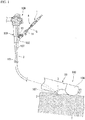
- Fig. 1 is a schematic diagram illustrating a configuration of an endoscope system 200 including an endoscopic treatment tool 1 (hereinafter, referred to as a "treatment tool") according to an embodiment of the present invention.
- the treatment tool 1 according to the present embodiment used in a state that the treatment tool 1 is inserted into a treatment tool insertion channel (hereinafter, simply referred to as a "channel") 107 formed in an inserting portion 101 of an endoscope 100, and a holder 13 to be described later is fixed to a proximal end channel port 102 of the endoscope 100.
- a treatment tool insertion channel hereinafter, simply referred to as a "channel”
- central axis C is used to include the central axis C of the manipulating unit and a longitudinal axis.
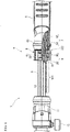
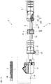
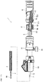
- Fig. 2 is a bottom view illustrating the treatment tool 1.
- Figs. 5 and 6 are partial cross-sectional views illustrating a manipulating unit 4 of the treatment tool 1.
- Fig. 5 illustrates the manipulating unit 4 in a state in which a distal end of a puncture needle 3 protrudes from a sheath 2.
- Fig. 6 illustrates the manipulating unit 4 in a state in which a distal end of the puncture needle 3 is accommodated in the sheath 2.
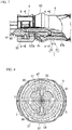
- Fig. 7 is an enlarged view of Fig. 6 , which is a partial cross-sectional view of a distal end portion of a needle slider 6 and a stopper 8.
- Fig. 8 is a cross-sectional view taken along line A-A illustrated in Fig. 7 .
- the treatment tool 1 includes a sheath 2, a puncture needle (treatment portion) 3, and a manipulating unit 4.
- the sheath 2 and the puncture needle 3 are provided over the entire length of the treatment tool 1, and the manipulating unit 4 is provided at the proximal end portion of the sheath 2 and the puncture needle 3.
- the sheath 2 is an elongated tubular member having flexibility.
- the sheath 2 has an outer diameter that is capable of being inserted into a channel 107 of the endoscope 100.
- a lumen through which the puncture needle 3 is inserted is formed inside the sheath 2 over the entire length in the longitudinal direction.
- the sheath 2 is formed of a resin, a metal coil, or the like.
- the puncture needle 3 is constituted by a needle tube of a hollow member. A distal end of the puncture needle 3 is formed to be inclined with respect to the central axis C and sharpened so that the distal end thereof is configured to be capable of being inserted into the living tissue.
- the puncture needle has flexibility and is made of a metal having elasticity that easily returns to a linear state even if it is bent by an external force.
- the manipulating unit 4 includes a manipulation main body 5, a needle slider (a slider) 6, a first locking mechanism 7 (see Fig. 6 ), a stopper (a second locking mechanism) 8, a fixing mechanism 9, a restricting portion 10, and a sheath adjuster 11.
- Fig. 3 is a bottom view illustrating a part of the manipulation main body 5.
- Fig. 4 is a side view illustrating a part of the manipulation main body 5.
- the manipulation main body 5 is a tubular long shaft member formed of resin or the like. As illustrated in Fig. 4 , two slider grooves 51 extending in parallel at positions symmetrical with respect to the central axis are formed on an outer peripheral surface of the manipulation main body 5.
- a rack 52 is formed on the outer peripheral surface of the manipulation main body 5.
- a plurality of teeth extending in a direction orthogonal to the central axis C are formed to be lined in a direction of the central axis C to form the rack 52.
- the rack 52 and the slider groove 51 are disposed on the outer peripheral surface of the manipulation main body 5 so that the rack 52 is positioned between the two slider grooves 51.
- the rack 52 includes a first region (a first fixing portion) 521 provided on the distal side and a second region (a second fixing portion) 522 provided on the proximal side.
- the first region 521 is longer than the second region 522 in the longitudinal direction.
- the restricting portion 10 is provided between the first region 521 and the second region 522.
- the restricting portion 10 is a protruding portion which connects a top portion of a tooth 521a provided on the most proximal end side of the first region 521 and a top portion of a tooth 522a provided on the most distal end side of the second region to extend in the longitudinal direction of the manipulation main body 5, and has a trapezoidal cross section orthogonal to the central axis C.
- the restricting portion 10 includes a wall portion (an abutting surface) 10a formed to protrude radially outward from the manipulation main body 5 from a concave portion (a bottom portion) of the teeth of the rack 52.
- the wall portion 10a is inclined from an upper surface (a surface farthest from the central line C) of the restricting portion 10 toward the outer peripheral surface of the manipulation main body 5.
- the restricting portion 10 is configured such that a claw portion of a fixing mechanism to be described later is not capable of being engaged.
- a pair of protrusions 54 and 55 are formed on the proximal end side of the manipulation main body 5.
- the pair of protrusions 54 and 55 are formed to protrude radially outward from the outer periphery of the manipulation main body 5.
- the first protrusion 54 which is one of the pair of protrusions 54 and 55, is provided on the proximal end side of the rack 52, and the other, the second protrusion 55, is provided symmetrical to the first protrusion 54 across the central axis C.
- a pair of guide convex portions 57 extending in the longitudinal direction are formed at a proximal end portion of the manipulation main body 5.
- the pair of protrusions 54 and 55 are formed in the pair of guide convex portions 57.
- a communication passage 61 extending in the direction of the central axis C is provided in the needle slider 6.
- the puncture needle 3 is inserted through the communication passage 61 over the entire length, and the puncture needle 3 and the needle slider 6 are fixed.
- a pair of guide grooves 66 are formed in the communication passage 61 of the needle slider 6 in the longitudinal direction.
- a convex portion 67 protruding toward the center of the needle slider 6 is formed at the bottom of each of the guide grooves 66.
- the first locking mechanism 7 is constituted by the convex portion 67 of the needle slider 6 and the protrusions 54 and 55 of the manipulation main body 5.
- An enlarged diameter portion 63 having an outer diameter larger than that of the distal end of the needle slider 6 is formed at a distal end portion of the needle slider 6.
- the enlarged diameter portion 63 has a greater outer diameter than the proximal side and the distal side thereof such that an outer peripheral surface of the needle slider 6 is formed to bulge.
- the enlarged diameter portion 63 functions as a finger hook portion on which the operator hooks his or her finger when advancing and retracting the needle slider 6.
- a proximal end opening portion 62 is formed at a proximal end portion of the needle slider 6.
- An opening of a proximal end of the puncture needle communicates with the proximal end opening portion 62, and a stylet 64 (see Fig. 11 ) is insertable into the puncture needle from the proximal end opening portion 62.
- the proximal end opening portion 62 is configured to be capable of connecting a known syringe or the like, and is configured to be capable of suctioning an object inside the puncture needle.
- the stopper 8 includes a substantially cylindrical stopper main body 81 and a fixing mechanism 9.
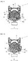
- Fig. 9 is a cross-sectional view taken along line B-B illustrated in Fig. 7 .
- Fig. 10 is a cross-sectional view illustrating the fixing mechanism 9 in the fixing release state in the same cross section as Fig. 9 .
- a pair of protruding portions 94 that is insertable into the slider groove 51 of the manipulation main body 5 are formed in a lumen of the stopper main body 81 in the direction of the central axis C.
- the fixing mechanism 9 is attached to the stopper main body 81 so as to be slidable with respect to the stopper main body 81 in the direction orthogonal to the central axis C.
- a claw portion (claw) 90 capable of engaging with a rack of the manipulation main body 5 is formed in the fixing mechanism 9.
- the claw portion 90 is formed in a convex shape corresponding to the shape of the concave portion of the teeth of the rack 52.
- an end portion 90a of the claw portion 90 on the slide button 91 side is inclined downward in Figs. 9 and 10 , and has a tapered shape in which the thickness in the direction orthogonal to the central axis C gradually decreases.
- the fixing mechanism 9 includes a pair of slide buttons 91 and 92 on both sides across the central axis C.
- the first slide button 91 of the pair of slide buttons 91 and 92 and the claw portion 90 are integrally formed, and in the other, the second slide button 92, a pressing portion 93 which presses the first slide button 91 is provided.
- the pair of slide buttons 91 and 92 are configured to be slidable in the direction orthogonal to the central axis C (a direction indicated by an arrow D in Figs. 9 and 10 ).
- the rack 52 has the first region 521 and the second region 522.
- the first region 521 is set so that the distal end of the puncture needle 3 protrudes from the sheath 2.
- the distal end of the puncture needle 3 slightly protrudes from a distal end of the sheath 2.
- the distal end of the puncture needle 3 is configured to be positioned and accommodated at the proximal end side by a predetermined distance or more from the distal end of the sheath 2.
- the restricting portion 10 is formed in the wall portion 10a without forming the teeth of the rack 52, the restricting portion 10 is unengageable with the claw portion 90. Therefore, the restricting portion 10 is a part at which the stopper 8 is incapable of being fixed with respect to the manipulation main body 5.
- the restricting portion 10 is set in accordance with a positional relationship between the manipulation main body 5 and the needle slider 6 when the distal end of the puncture needle 3 is accommodated in the sheath 2 and the distance from the distal end of the sheath 2 to the distal end of the puncture needle 3 is within a predetermined range.
- the end portion 90a of the claw portion 90 has a tapered shape
- the wall portion 10a of the restricting portion 10 and the end portion 90a of the claw portion 90 come in to line contact with each other, and the claw portion 90 comes into contact with the restricting portion 10, the force applied to the end portion 90a of the claw portion 90 and the restricting portion 10 is dispersed.
- the regulating force of the end portion 90a of the claw portion 90 and the restricting portion 10 is improved.
- the restricting portion 10 has a trapezoidal cross section orthogonal to the central axis C.
- the shape of the restricting portion 10 is not limited thereto, and the restricting portion 10 may be a quadrangular prism-shaped protruding portion having a rectangular cross section orthogonal to the center axis C.
- a relative position between the puncture needle 3 and the sheath 2 in the direction of the central axis C may change. Further, in some cases, due to dimensional errors that can occur during manufacture, errors may occur between the relative position of the puncture needle 3 to the sheath 2, and the relative position of the manipulation main body 5 to the needle slider 6. Under the influence of such factors, even when the distal end of the puncture needle 3 is designed to be positioned closer to the proximal side than the distal end of the sheath 2, in some cases, the puncture needle 3 may protrude from the distal end of the sheath 2.
- the restricting portion 10 is provided to inhibit the stopper 8 from being positioned between the first region 521 and the second region 522 of the rack 52. As a result, it is possible to secure a state in which the puncture needle 3 is reliably accommodated in the sheath 2.
- the sheath adjuster 11 is a tubular member, and the distal end of the manipulation main body 5 is inserted through the sheath adjuster 11.
- a slide lock 12 attachable to detachable from the proximal end mouth ring 108 of the endoscope 100 is provided at a distal end portion of the sheath adjuster 11.
- Concavities and convexities are provided on the outer peripheral surface of the sheath adjuster 11 so that the operator can easily grip the sheath adjuster 11.
- a fixing screw 15 is attached to the sheath adjuster 11.
- a holder 13 is provided on the distal side of the slide lock 12.
- the holder 13 is fixed to the sheath adjuster 11.
- the distal end side of the manipulating unit 109 (see Fig. 1 ) of the endoscope 100 is disposed in the holder 13.
- the sheath 2, the puncture needle 3, the manipulation main body 5, the needle slider 6, the stopper 8 and the sheath adjuster 11 of the treatment tool 1 are configured as follows.
- the puncture needle 3 is inserted into the manipulation main body 5, and the proximal end portion of the puncture needle 3 and the needle slider 6 are fixed.
- the manipulation main body 5 and the proximal end of the sheath 2 are fixed.
- the proximal end portion of the manipulation main body 5 is inserted into the communication passage 61 from a distal end side of the needle slider 6.
- the needle slider 6 is configured to be capable of advancing and retracting in the direction of the central axis C with respect to the manipulation main body 5. Since the needle slider 6 advances and retracts while the guide convex portion 57 of the manipulation main body 5 slides in the guide groove 66, the position of the needle slider 6 in the circumferential direction with respect to the manipulation main body 5 is fixed.
- the needle slider 6 is provided to adjust a position of the puncture needle 3 with respect to the sheath 2.
- the puncture needle 3 is configured to advance and retract with respect to the sheath 2 in accordance with advance and retract manipulation of the needle slider 6 with respect to the manipulation main body 5.
- the positional relationship between the protrusions 54 and 55 and the convex portion 67 is set so that the protrusions 54 and 55 of the manipulation main body 5 are positioned on the proximal end portion 67b side of the convex portion 67 when the distal end of the puncture needle 3 is in the position accommodated in the sheath 2.
- the protrusions 54 and 55 of the manipulation main body 5 abut a distal end portion 67a of the convex portion 67 with sliding of the needle slider 6 toward the proximal side.
- both end portions in the direction of the central axis C of the convex portion may be formed in a square shape.
- the manipulation main body 5 is inserted into a lumen 82 formed along the central axis C of the stopper main body 81.
- the stopper 8 is capable of advancing and retracting in the direction of the central axis C with respect to the manipulation main body 5, and is provided on more distal side than the needle slider 6.
- the stopper 8 is provided for regulating the advanced position of the needle slider 6 with respect to the manipulation main body 5. Since the pair of protruding portions 84 slide in the slider groove 51 when the stopper 8 advancing and retracting with respect to the manipulation main body 5, a position of the stopper 8 in the circumferential direction with respect to the manipulation main body 5 is fixed.
- the fixing mechanism 9 is configured to cause the slide buttons 91 and 92 to slide in a direction orthogonal to the central axis C (a direction of an arrow D illustrated in Figs. 9 and 10 ), thereby switching a state in which the stopper 8 is fixed to the manipulation main body 5 and a state of releasing the fixing.
- the claw portion 90 is engaged with the concave portion 523, the movement of the stopper 8 with respect to the manipulation main body 5 is restricted.
- the claw portion 90 moves in the direction of the arrow D illustrated in Fig. 9 to switch between a fixed state in which the claw portion 90 is engaged with the concave portion 523 of the teeth of the rack 52 ( Fig. 9 ) and a fixing release state in which the engagement between the claw portion 90 and the concave portion 523 is released ( Fig. 10 ).
- An amount of force (second amount of force) which locks the stopper 8 to the manipulation main body 5 is greater than an amount of force amount (first amount of force) which locks the needle slider 6 to the manipulation main body 5 when the needle slider 6 is temporarily fixed to the manipulation main body 5 by the first locking mechanism 7. Therefore, even if engagement in the first locking mechanism 7 is released and the needle slider 6 moves to the distal side due to its own weight or the addition of an external force not intended by the operator, the needle slider 6 abuts on the stopper 8, and the movement of the needle slider 6 is restricted. As a result, the needle slider 6 is prevented from moving to more distal side from the predetermined position, and it is possible to maintain the state in which the distal end of the puncture needle 3 is accommodated in the sheath 2.
- the sheath adjuster 11 is provided for adjusting a protruding length of the sheath 2 from the channel 107.
- the position of the sheath adjuster 11 with respect to the manipulation main body 5 is fixed by the fixing screw 15, and the protruding length of the sheath 2 from the channel 107 is fixed.
- a support pipe 14 protrudes from the distal end portion of the sheath adjuster 11. A distal end portion of the support pipe 14 is inserted into the channel 107 when the treatment tool 1 is attached to the endoscope 100.
- the support pipe 14 is inserted into the manipulation main body 5.
- the sheath 2 is inserted into the support pipe 14, and the proximal end portion of the sheath 2 protrudes from a proximal end of the support pipe 14 and is fixed to the manipulation main body 5.
- Figs. 11 to 13 illustrate the sheath 2 and the puncture needle 3 at the distal end in an enlarged manner to illustrate a relationship between the positional relationship between the sheath 2 and the puncture needle 3 and the form of the manipulating unit 4.
- the endoscope 100 is inserted into the body cavity of a patient by a known procedure and advanced to the vicinity of the biopsy target tissue T to be collected or the target organ.
- the operator performs a manipulation of holding a finger on the enlarged diameter portion 63 of the needle slider 6 and pulling the needle slider 6 toward the proximal side.
- the protrusions 54 and 55 of the manipulation main body 5 abut on the distal end portion 67a of the convex portion 67 of the needle slider 6, and the operator feel resistance at the time of pulling.
- the operator performs the manipulation of further pulling the needle slider 6 toward the proximal side, since the protrusions 54 and 55 ride on the convex portion 67, the distal end portion of the needle slider 6 slightly bends.
- the pressing force to the needle slider 6 due to the protrusions 54 and 55 is released and the bending of the needle slider 6 is released.
- the needle slider 6 is locked to the manipulation main body 5 by the first locking mechanism 7.
- the needle slider 6 slightly vibrates, and a sound is generated to generate the click feeling, and the operator senses the click feeling on the hand for grasping the needle slider 6.
- the operator recognizes that the needle slider 6 moves toward the proximal side by a predetermined amount and the distal end of the puncture needle 3 is accommodated in the sheath 2.
- the manipulation of moving the needle slider 6 to the proximal side by holding the finger on the enlarged diameter portion 63 is not limited to the pulling manipulation, and it may be a manipulation of pushing the enlarged diameter portion 63 toward the distal side with the hand, depending on the method in which the operator holds the needle slider 6.
- the operator performs a manipulation of fixing the stopper 8 to the second region 522.
- the operator performs a manipulation of moving the stopper 8 toward the proximal end side with respect to the manipulation main body 5.
- the stopper 8 is moved to the proximal end side up to a position at which the stopper 8 abuts on the distal end of the needle slider 6, and the first slide button 91 is caused to slide in the direction D orthogonal to the central axis C to lock the claw portion 90 to the second region 522.
- the claw portion 90 when the claw portion 90 is positioned in the restricting portion 10, the claw portion 90 abuts on the wall portion 10a and even if the operator manipulates the first slide button 91, the first slide button 91 is immovable. As a result, the operator can recognize that the stopper 8 is in a position where the stopper 8 cannot be fixed, by manipulation of the first slide button 91. Therefore, the operator further moves the needle slider 6 to the proximal side to lock the claw portion 90 in the second region 522 as illustrated in Fig. 13 .
- the operator inserts the treatment tool 1 into the channel 107, inserts the holder 13 into the proximal end channel port 102, causes the slide lock 12 to slide in the direction orthogonal to the central axis C and engages the slide lock 12 with the proximal end channel port 102, thereby fixing the manipulating unit 4 to the endoscope 100.
- the interior of the channel 107 is not damaged by the puncture needle 3, and the treatment tool 1 is capable of being smoothly inserted into the channel 107.
- the protrusion length of the sheath 2 from the channel 107 is adjusted.
- the operator loosens the fixing screw 15, and advances the sheath adjuster 11 with respect to the manipulation main body 5, while observing the sheath 2 and the inside of the body by an optical imaging mechanism (not illustrated) and an ultrasonic scanning mechanism 104 provided in the endoscope 100, thereby adjusting the amount of protrusion of the sheath 2 from the distal end of the channel 107 to an appropriate amount.
- the fixing screw 15 penetrates the sheath adjuster 11 and is fitted into a screw hole (not illustrated) provided in the manipulation main body 5. When the fixing screw 15 is tightened against the manipulation main body 5, the sheath adjuster 11 is pressed against the manipulation main body 5 to fix the sheath adjuster 11 to the manipulation main body 5 in a non-slidable manner.
- the operator presses the second slide button 92 of the stopper 8 in the direction D orthogonal to the central axis C, and releases the fixing of the stopper 8 with respect to the manipulation main body 5.
- the first slide button 91 is pushed to release the locking between the claw portion 90 and the second region 522, the fixing of the stopper 8 with respect to the manipulation main body 5 is released.
- the operator moves the stopper 8 to the distal end side with respect to the manipulation main body 5, adjusts the amount of protrusion of the puncture needle 3 with respect to the sheath 2 to a desired amount of protrusion, and presses the slide button 91 to fix the slide button 91 to the teeth of the first region 521.
- the distal end of the puncture needle 3 enters a state capable of protruding from the sheath 2.
- a scale (not illustrated) provided in the manipulation main body 5 may be referred to.
- the distal end of the puncture needle 3 is inserted into the biopsy target tissue T.
- the puncture needle 3 exposed from the surface of the biopsy target tissue T can be observed by the optical imaging mechanism, and the distal end portion of the puncture needle 3 inserted into the biopsy target tissue T can be observed by the ultrasonic scanning mechanism 104.
- the operator extracts the stylet 64 from the puncture needle 3. Thereafter, a known syringe is fixed to the proximal end opening portion 62, and the tissue collected in the distal end portion of the puncture needle 3 is suctioned and collected.
- the needle slider 6 When the necessary amount of tissue can be collected, the needle slider 6 is retracted to the proximal side with respect to the manipulation main body 5, and the distal end of the puncture needle 3 is accommodated in the sheath 2. Specifically, the operator pulls the enlarged diameter portion 63 of the needle slider 6 toward the proximal side, and moves the needle slider 6 to the proximal side. When the needle slider 6 is pulled by a predetermined amount or more, the needle slider 6 is locked to the manipulation main body 5 by the first locking mechanism 7. At this time, as described above, a click feeling occurs and the operator can recognize that the distal end of the puncture needle 3 is sufficiently accommodated in the sheath 2.
- the operator retracts the stopper 8 to the proximal end side until the stopper 8 comes into contact with the distal end of the needle slider 6, causes the first slide button 91 to slide in the direction D orthogonal to the central axis C, and locks the second region 522 and the claw portion 90.
- a state in which the distal end of the puncture needle 3 is accommodated in the sheath 2 is maintained.
- the slide lock 12 is removed from the proximal end channel port 102 of the endoscope 100, and the treatment tool 1 is extracted from the channel 107.
- the distal end of the puncture needle 3 is reliably accommodated in the sheath 2, the interior of the channel 107 is not damaged by the puncture needle 3, and the treatment tool 1 is capable of being smoothly extracted from the channel 107.
- the endoscope 100 is extracted from the patient and a series of manipulations is completed.
- the needle slider 6 is temporarily fixed at the position at which the distal end of the puncture needle 3 is accommodated in the sheath 2 by the first locking mechanism 7, and the advance of the needle slider 6 is capable of being restricted by the stopper 8.
- the needle slider 6 it is possible to prevent the needle slider 6 from advancing at an unintended timing and the distal end of the puncture needle 3 from protruding from the distal end of the sheath 2 in two stages.
- the operator can recognize that the distal end of the puncture needle 3 are accommodated in the sheath 2 by their ears and the feeling of the grasped needle slider 6.
- the stopper 8 is capable of locking the needle slider 6 with the second amount of force greater than the first amount of force for locking the needle slider 6 in the first locking mechanism 7, for example, even when the locking of the needle slider 6 due to the first locking mechanism 7 is released by the own weight of the needle slider 6, the advance of the needle slider 6 is capable of being reliably restricted by the stopper 8.
- the treatment tool 1 includes the fixing mechanism 9 that is capable of fixing the stopper 8 to the manipulation main body 5 by sliding with respect to the manipulation main body 5, the operator can fix the stopper 8 to the manipulation main body 5 by a simple manipulation.
- the fixing mechanism 9 since the fixing mechanism 9 has a configuration in which the claw portion 90 is movable by the slide button, the operator can switches between the fixed state and the fixing release state of the stopper 8 by the manipulation of pressing one of a pair of slide buttons with a finger grasping the manipulating unit 4. Therefore, it is possible to perform fixing or fixing release of the stopper 8 to the manipulation main body 5 with a simple manipulation.
- the stopper 8 Since the treatment tool 1 is provided with the restricting portion 10 between the first region 521 and the second region 522, the stopper 8 is not locked from the state in which the distal end of the puncture needle 3 is positioned at an approximately equal to the distal end of the sheath 2 to a state in which the distal end of the puncture needle 3 is securely accommodated in the sheath 2. Therefore, when the operator moves the stopper 8 toward the proximal end side from the first region 521, the stopper 8 cannot be fixed by the restricting portion 10, and when moving the stopper 8 to the second region 522 on the proximal end side from the restricting portion 10, the stopper 8 can be fixed to the manipulation main body 5.
- the treatment tool 1 by including the first locking mechanism 7, the stopper 8, and the restricting portion 10, when the needle slider 6 and the stopper 8 are locked at the proximal end side, the distal end of the puncture needle 3 is in a state of being reliably accommodated in the sheath 2. Therefore, the operator can recognize that the distal end of the puncture needle 3 is reliably accommodated in the sheath 2 without visually checking the manipulating unit 4, and it is possible to improve manipulating property.
- the fixing mechanism 9 has a configuration in which the claw portion 90 is movable by the slide buttons 91 and 92 as an example, but the fixing mechanism 9 is not limited to this configuration.
- the stopper main body may fix to the manipulation main body by causing a screw that is capable of being fitted into a concave portion formed on the outer peripheral surface of the manipulation main body 5 to slide (for example, to be screwed) from the radially outer side of the stopper toward the central axis C.
- the slide buttons 91 and 92 are adopted, the operator can switch between the fixed state and the fixing release state, only by performing the slide manipulation of the slide button slide with the finger of the hand grasping the manipulating unit 4. Therefore, the operator can manipulate with one hand, manipulation of visual observation is not necessary, and the manipulating property is excellent.
- the configuration of the endoscopic treatment tool is not limited thereto.
- the stopper 8 may be able to restrict the advance of the needle slider 6 when the first locking mechanism 7 is released. In a state in which the needle slider is locked by the first locking mechanism 7, the distal end of the needle slider 6 and the proximal end of the stopper 8 may not abut on each other.
- first locking mechanism 7 is configured by the two convex portions 67 and the two protrusions 54 and 55 .
- the number of convex portions and the number of protrusions is not limited thereto, and at least one set or more of first locking mechanisms may be provided between the manipulation main body 5 and the needle slider 6.
- the first locking mechanism 7 the configuration in which the convex portion 67 and the protrusions 54 and 55 are engaged with each other is illustrated, but the configuration of the first locking mechanism 7 is not limited thereto.
- the first locking mechanism 7 may be configured so that an O-ring is attached to the outer periphery of the manipulation main body 5, the O-ring abuts on the communication passage of the needle slider, the inner diameter of the communication passage is changed by the relative position between the needle slider and the manipulation main body 5, and a press-fitted state between the O-ring and the communication passage changes.
- an endoscopic treatment tool capable of holding a state in which a treatment portion such as a needle is accommodated in a sheath by a simple manipulation.
Abstract
Description
- The present invention relates to an endoscopic treatment tool.
- An inspection method called a biopsy, in which a small amount of living tissue is collected and observed with a microscope, is known. In a biopsy that uses a puncture needle consisting of a needle tube, for example, after bringing an endoscope insertion portion close to an examination target part, a sheath accommodating the puncture needle is caused to protrude from a treatment tool channel. Next, by manipulating a manipulating unit provided on a proximal end side of the puncture needle under ultrasonic observation, the puncture needle is caused to protrude from the sheath and puncture the examination target part, the living tissue is collected in the puncture needle, and the puncture needle is retracted into the sheath and extracted from the body.
-
Patent Document 1 discloses the endoscopic puncture device having a structure which has an automatic puncture function for protruding the puncture needle at a high speed, and includes a switch mechanism capable of switching between a restricted state that prevents the operation of the automatic puncture function until a distal end of the puncture needle is disposed at a predetermined position and a restriction release state that allows protruding of the puncture needle. - In the endoscopic puncture device of
Patent Document 1, a sheath capable of being inserted into the treatment tool channel of the insertion portion of the endoscope is disposed outside the puncture needle in order to prevent an inner surface of the treatment tool channel from being damaged by the sharp distal end of the puncture needle. - When the puncture needle advances and retracts in the treatment tool channel, the distal end of the puncture needle is required to be accommodated in the sheath. The endoscopic puncture device of
Patent Document 1 has a structure that temporarily fixes a needle slider when the needle slider is manipulated to retract until the distal end of the puncture needle is accommodated in the sheath. - [Patent Document 1] Japanese Unexamined Patent Application, First Publication No.
2001-037765 - Since the endoscopic puncture device of
Patent Document 1 has a configuration in which an elastic ring is fitted into a click groove to temporarily support the needle slider, there is a possibility of the needle slider advancing and the distal end of the puncture needle protruding from the sheath when an unexpected external force is applied by an operator touching the needle slider or due to the weight of the manipulating unit itself in a state in which the puncture needle is inserted into the treatment tool channel. - Further, since the treatment tool channel bends or meanders along a body cavity, in some cases, a relative position between the puncture needle and the sheath in a longitudinal axis direction may change due to the bending of the sheath. Therefore, when the puncture needle is accommodated in the sheath, it is necessary to sufficiently secure a distance from the distal end of the puncture needle to the distal end of the sheath.
- On the other hand, when living tissue is collected, since the operator performs the manipulation while observing an image captured by an imaging unit of an endoscope, it is preferable to perform the manipulation without viewing the manipulating unit in one's hand. However, in the conventional endoscopic puncture device, for the purpose of preventing erroneous manipulation or sufficiently securing the distance of the puncture needle from the distal end of the sheath, since the operator needs to manipulate the manipulating unit while viewing a scale and the like provided on the manipulating unit, the manipulation is complicated. Therefore, an improvement in manipulating property at the time of advance and retract manipulation of the puncture needle has been desired.
- In view of the above circumstances, an object of the present invention is to provide an endoscopic treatment tool capable of reliably maintaining a state in which a treatment portion such as a needle is accommodated in a sheath by a simple manipulation.
- An endoscopic treatment tool according to a first aspect of the present invention includes a sheath inserted into a treatment tool insertion channel of an endoscope; a treatment portion which is inserted into the sheath and is capable of protruding from and retracting into a distal end of the sheath; a manipulation main body fixed to a proximal end of the sheath and formed along a longitudinal axis of the sheath; a slider to which the treatment portion is fixed and is provided in the manipulation main body, the slider advancing and retracting in a longitudinal axis direction with respect to the manipulation main body to cause the treatment portion to protrude from and retract into the sheath; a first locking mechanism which locks the slider with a first amount of force at a position at which a distal end of the treatment portion is accommodated in the sheath in accordance with a retracting manipulation of the slider; a second locking mechanism which is provided at further distal side than the first locking mechanism, is capable of advancing and retracting in the longitudinal axis direction with respect to the manipulation main body, the second locking mechanism being locked to the manipulation main body with a second amount of force greater than the first amount of force, and restricts advance of the slider by abutting the slider; a fixing mechanism provided in the second locking mechanism and fixed to the manipulation main body by sliding with respect to the manipulation main body to fix a position of the second locking mechanism with respect to the manipulation main body; and a restricting portion which restricts fixing of the fixing mechanism to the manipulation main body.
- A second aspect of the present invention is the endoscopic treatment tool according to the first aspect, wherein a distal end of the slider may abut the second locking mechanism in a state in which the slider is locked by the first locking mechanism.
- A third aspect of the present invention is the endoscopic treatment tool according to the first or second aspect, wherein a first fixing portion may be formed on an outer peripheral surface of the manipulation main body at a distal end side of a region in which the slider advances and retracts, a second fixing portion may be formed on a proximal end side thereof, the second locking mechanism may be capable of being fixed by the fixing mechanism by allowing the sliding of the fixing mechanism through the first fixing portion and the second fixing portion, and the restricting portion may be formed between the first fixing portion and the second fixing portion.
- A fourth aspect of the present invention is the endoscopic treatment tool according to the third aspect, wherein the first fixing portion may be formed in a region in which the slider is located so that the distal end of the treatment portion protrudes from the distal end of the sheath, and the second fixing portion may be formed in a region in which the slider is located so that the distal end of the treatment portion is accommodated in the sheath.
- A fifth aspect of the present invention is the endoscopic treatment tool according to the first aspect, wherein the first fixing portion and the second fixing portion may be formed by a plurality of concavities and convexities continuously disposed in the longitudinal axis direction, a claw which engages with the concavities and convexities by moving with respect to the concavities and convexities may be formed in the fixing mechanism, and the restricting portion of the manipulation main body may include an abutting surface protruding further outward in a radial direction of the manipulating unit than the concave portion of the concavities and convexities.
- A sixth aspect of the present invention is the endoscopic treatment tool according to the first aspect, wherein the first locking mechanism may include a click mechanism which generates a click feeling when the slider is retracted to a position at which the slider is locked by the first locking mechanism.
- According to the endoscopic treatment tool, it is possible to maintain the state in which the treatment portion such as a needle is accommodated in the sheath by a simple manipulation.
-
-
Fig. 1 is a schematic diagram illustrating a configuration of an endoscope system including an endoscopic treatment tool according to an embodiment of the present invention. -
Fig. 2 is a bottom view illustrating the endoscopic treatment tool according to the embodiment of the present invention. -
Fig. 3 is a bottom view illustrating a part of a manipulation main body of the endoscopic treatment tool according to the embodiment of the present invention. -
Fig. 4 is a side view illustrating a part of the manipulation main body of the endoscopic treatment tool according to the embodiment of the present invention. -
Fig. 5 is a partial cross-sectional view illustrating a manipulating unit of the endoscopic treatment tool according to the embodiment of the present invention. -
Fig. 6 is a partial cross-sectional view illustrating the manipulating unit of the endoscopic treatment tool according to the embodiment of the present invention. -
Fig. 7 is a partial cross-sectional view illustrating a first locking mechanism and a stopper according to the embodiment of the present invention. -
Fig. 8 is a cross-sectional view taken along line A-A inFig. 7 . -
Fig. 9 is a cross-sectional view taken along the line B-B inFig. 7 . -
Fig. 10 is a cross-sectional view of the stopper according to the embodiment of the present invention. -
Fig. 11 is a diagram illustrating the operation of the endoscopic treatment tool according to the embodiment of the present invention. -
Fig. 12 is a diagram illustrating the operation of the endoscopic treatment tool according to the embodiment of the present invention. -
Fig. 13 is a diagram illustrating the operation of the endoscopic treatment tool according to the embodiment of the present invention. - Hereinafter, an endoscopic treatment tool including a puncture needle (an aspiration biopsy needle) as an endoscopic treatment tool according to an embodiment of the present invention will be described with reference to the accompanying drawings.
-
Fig. 1 is a schematic diagram illustrating a configuration of an endoscope system 200 including an endoscopic treatment tool 1 (hereinafter, referred to as a "treatment tool") according to an embodiment of the present invention. Thetreatment tool 1 according to the present embodiment used in a state that thetreatment tool 1 is inserted into a treatment tool insertion channel (hereinafter, simply referred to as a "channel") 107 formed in aninserting portion 101 of anendoscope 100, and aholder 13 to be described later is fixed to a proximalend channel port 102 of theendoscope 100. - In the following description, a side positioned at a manipulating unit manipulated by the operator is referred to as a proximal end, and a side inserted into the body is referred to as a distal end. Further, in the description of each part, in some cases the term "central axis C" is used to include the central axis C of the manipulating unit and a longitudinal axis.
-
Fig. 2 is a bottom view illustrating thetreatment tool 1.Figs. 5 and6 are partial cross-sectional views illustrating a manipulatingunit 4 of thetreatment tool 1.Fig. 5 illustrates the manipulatingunit 4 in a state in which a distal end of apuncture needle 3 protrudes from asheath 2.Fig. 6 illustrates the manipulatingunit 4 in a state in which a distal end of thepuncture needle 3 is accommodated in thesheath 2.Fig. 7 is an enlarged view ofFig. 6 , which is a partial cross-sectional view of a distal end portion of aneedle slider 6 and astopper 8.Fig. 8 is a cross-sectional view taken along line A-A illustrated inFig. 7 . - As illustrated in
Fig. 2 , thetreatment tool 1 includes asheath 2, a puncture needle (treatment portion) 3, and a manipulatingunit 4. Thesheath 2 and thepuncture needle 3 are provided over the entire length of thetreatment tool 1, and the manipulatingunit 4 is provided at the proximal end portion of thesheath 2 and thepuncture needle 3. - The
sheath 2 is an elongated tubular member having flexibility. Thesheath 2 has an outer diameter that is capable of being inserted into achannel 107 of theendoscope 100. A lumen through which thepuncture needle 3 is inserted is formed inside thesheath 2 over the entire length in the longitudinal direction. Thesheath 2 is formed of a resin, a metal coil, or the like. - The
puncture needle 3 is constituted by a needle tube of a hollow member. A distal end of thepuncture needle 3 is formed to be inclined with respect to the central axis C and sharpened so that the distal end thereof is configured to be capable of being inserted into the living tissue. The puncture needle has flexibility and is made of a metal having elasticity that easily returns to a linear state even if it is bent by an external force. - The manipulating
unit 4 includes a manipulationmain body 5, a needle slider (a slider) 6, a first locking mechanism 7 (seeFig. 6 ), a stopper (a second locking mechanism) 8, afixing mechanism 9, a restrictingportion 10, and asheath adjuster 11. -
Fig. 3 is a bottom view illustrating a part of the manipulationmain body 5.Fig. 4 is a side view illustrating a part of the manipulationmain body 5. The manipulationmain body 5 is a tubular long shaft member formed of resin or the like. As illustrated inFig. 4 , twoslider grooves 51 extending in parallel at positions symmetrical with respect to the central axis are formed on an outer peripheral surface of the manipulationmain body 5. - As illustrated in
Figs. 3 and 4 , arack 52 is formed on the outer peripheral surface of the manipulationmain body 5. A plurality of teeth extending in a direction orthogonal to the central axis C are formed to be lined in a direction of the central axis C to form therack 52. Therack 52 and theslider groove 51 are disposed on the outer peripheral surface of the manipulationmain body 5 so that therack 52 is positioned between the twoslider grooves 51. - The
rack 52 includes a first region (a first fixing portion) 521 provided on the distal side and a second region (a second fixing portion) 522 provided on the proximal side. Thefirst region 521 is longer than thesecond region 522 in the longitudinal direction. The restrictingportion 10 is provided between thefirst region 521 and thesecond region 522. The restrictingportion 10 is a protruding portion which connects a top portion of atooth 521a provided on the most proximal end side of thefirst region 521 and a top portion of atooth 522a provided on the most distal end side of the second region to extend in the longitudinal direction of the manipulationmain body 5, and has a trapezoidal cross section orthogonal to the central axis C. The restrictingportion 10 includes a wall portion (an abutting surface) 10a formed to protrude radially outward from the manipulationmain body 5 from a concave portion (a bottom portion) of the teeth of therack 52. Thewall portion 10a is inclined from an upper surface (a surface farthest from the central line C) of the restrictingportion 10 toward the outer peripheral surface of the manipulationmain body 5. The restrictingportion 10 is configured such that a claw portion of a fixing mechanism to be described later is not capable of being engaged. - As illustrated in
Figs. 7 and 8 , a pair ofprotrusions main body 5. The pair ofprotrusions main body 5. Thefirst protrusion 54, which is one of the pair ofprotrusions rack 52, and the other, thesecond protrusion 55, is provided symmetrical to thefirst protrusion 54 across the central axis C. A pair of guideconvex portions 57 extending in the longitudinal direction are formed at a proximal end portion of the manipulationmain body 5. The pair ofprotrusions convex portions 57. - As illustrated in
Fig. 5 , acommunication passage 61 extending in the direction of the central axis C is provided in theneedle slider 6. Thepuncture needle 3 is inserted through thecommunication passage 61 over the entire length, and thepuncture needle 3 and theneedle slider 6 are fixed. - As illustrated in
Fig. 8 , a pair ofguide grooves 66 are formed in thecommunication passage 61 of theneedle slider 6 in the longitudinal direction. Aconvex portion 67 protruding toward the center of theneedle slider 6 is formed at the bottom of each of theguide grooves 66. Thefirst locking mechanism 7 is constituted by theconvex portion 67 of theneedle slider 6 and theprotrusions main body 5. - An
enlarged diameter portion 63 having an outer diameter larger than that of the distal end of theneedle slider 6 is formed at a distal end portion of theneedle slider 6. Theenlarged diameter portion 63 has a greater outer diameter than the proximal side and the distal side thereof such that an outer peripheral surface of theneedle slider 6 is formed to bulge. Theenlarged diameter portion 63 functions as a finger hook portion on which the operator hooks his or her finger when advancing and retracting theneedle slider 6. - As illustrated in
Fig. 2 , a proximalend opening portion 62 is formed at a proximal end portion of theneedle slider 6. An opening of a proximal end of the puncture needle communicates with the proximalend opening portion 62, and a stylet 64 (seeFig. 11 ) is insertable into the puncture needle from the proximalend opening portion 62. The proximalend opening portion 62 is configured to be capable of connecting a known syringe or the like, and is configured to be capable of suctioning an object inside the puncture needle. - As illustrated in
Fig. 5 , thestopper 8 includes a substantially cylindrical stoppermain body 81 and afixing mechanism 9.Fig. 9 is a cross-sectional view taken along line B-B illustrated inFig. 7 .Fig. 10 is a cross-sectional view illustrating thefixing mechanism 9 in the fixing release state in the same cross section asFig. 9 . A pair of protrudingportions 94 that is insertable into theslider groove 51 of the manipulationmain body 5 are formed in a lumen of the stoppermain body 81 in the direction of the central axis C. - The
fixing mechanism 9 is attached to the stoppermain body 81 so as to be slidable with respect to the stoppermain body 81 in the direction orthogonal to the central axis C. As illustrated inFigs. 7 and9 , a claw portion (claw) 90 capable of engaging with a rack of the manipulationmain body 5 is formed in thefixing mechanism 9. Theclaw portion 90 is formed in a convex shape corresponding to the shape of the concave portion of the teeth of therack 52. Further, as illustrated inFigs. 9 and 10 , anend portion 90a of theclaw portion 90 on theslide button 91 side is inclined downward inFigs. 9 and 10 , and has a tapered shape in which the thickness in the direction orthogonal to the central axis C gradually decreases. - The
fixing mechanism 9 includes a pair ofslide buttons first slide button 91 of the pair ofslide buttons claw portion 90 are integrally formed, and in the other, thesecond slide button 92, apressing portion 93 which presses thefirst slide button 91 is provided. The pair ofslide buttons Figs. 9 and 10 ). - As described above, the
rack 52 has thefirst region 521 and thesecond region 522. Thefirst region 521 is set so that the distal end of thepuncture needle 3 protrudes from thesheath 2. When theclaw portion 90 of thefixing mechanism 9 is engaged with the most proximal tooth in thefirst region 521, the distal end of thepuncture needle 3 slightly protrudes from a distal end of thesheath 2. On the other hand, when theclaw portion 90 is engaged with the teeth of thesecond region 522, the distal end of thepuncture needle 3 is configured to be positioned and accommodated at the proximal end side by a predetermined distance or more from the distal end of thesheath 2. - Since the restricting
portion 10 is formed in thewall portion 10a without forming the teeth of therack 52, the restrictingportion 10 is unengageable with theclaw portion 90. Therefore, the restrictingportion 10 is a part at which thestopper 8 is incapable of being fixed with respect to the manipulationmain body 5. The restrictingportion 10 is set in accordance with a positional relationship between the manipulationmain body 5 and theneedle slider 6 when the distal end of thepuncture needle 3 is accommodated in thesheath 2 and the distance from the distal end of thesheath 2 to the distal end of thepuncture needle 3 is within a predetermined range. As described above, since theend portion 90a of theclaw portion 90 has a tapered shape, when thewall portion 10a of the restrictingportion 10 and theend portion 90a of theclaw portion 90 come in to line contact with each other, and theclaw portion 90 comes into contact with the restrictingportion 10, the force applied to theend portion 90a of theclaw portion 90 and the restrictingportion 10 is dispersed. Thus, the regulating force of theend portion 90a of theclaw portion 90 and the restrictingportion 10 is improved. - In the present embodiment, an example in which the restricting
portion 10 has a trapezoidal cross section orthogonal to the central axis C is illustrated. However, the shape of the restrictingportion 10 is not limited thereto, and the restrictingportion 10 may be a quadrangular prism-shaped protruding portion having a rectangular cross section orthogonal to the center axis C. - Specifically, when the
sheath 2 is bent due to the bending or meandering of thechannel 107, in some cases, a relative position between thepuncture needle 3 and thesheath 2 in the direction of the central axis C may change. Further, in some cases, due to dimensional errors that can occur during manufacture, errors may occur between the relative position of thepuncture needle 3 to thesheath 2, and the relative position of the manipulationmain body 5 to theneedle slider 6. Under the influence of such factors, even when the distal end of thepuncture needle 3 is designed to be positioned closer to the proximal side than the distal end of thesheath 2, in some cases, thepuncture needle 3 may protrude from the distal end of thesheath 2. However, in thetreatment tool 1 according to the present embodiment, the restrictingportion 10 is provided to inhibit thestopper 8 from being positioned between thefirst region 521 and thesecond region 522 of therack 52. As a result, it is possible to secure a state in which thepuncture needle 3 is reliably accommodated in thesheath 2. - The
sheath adjuster 11 is a tubular member, and the distal end of the manipulationmain body 5 is inserted through thesheath adjuster 11. As illustrated inFig. 2 , aslide lock 12 attachable to detachable from the proximal end mouth ring 108 of theendoscope 100 is provided at a distal end portion of thesheath adjuster 11. Concavities and convexities are provided on the outer peripheral surface of thesheath adjuster 11 so that the operator can easily grip thesheath adjuster 11. A fixingscrew 15 is attached to thesheath adjuster 11. - A
holder 13 is provided on the distal side of theslide lock 12. Theholder 13 is fixed to thesheath adjuster 11. The distal end side of the manipulating unit 109 (seeFig. 1 ) of theendoscope 100 is disposed in theholder 13. - The
sheath 2, thepuncture needle 3, the manipulationmain body 5, theneedle slider 6, thestopper 8 and thesheath adjuster 11 of thetreatment tool 1 are configured as follows. - The
puncture needle 3 is inserted into the manipulationmain body 5, and the proximal end portion of thepuncture needle 3 and theneedle slider 6 are fixed. The manipulationmain body 5 and the proximal end of thesheath 2 are fixed. The proximal end portion of the manipulationmain body 5 is inserted into thecommunication passage 61 from a distal end side of theneedle slider 6. Theneedle slider 6 is configured to be capable of advancing and retracting in the direction of the central axis C with respect to the manipulationmain body 5. Since theneedle slider 6 advances and retracts while the guideconvex portion 57 of the manipulationmain body 5 slides in theguide groove 66, the position of theneedle slider 6 in the circumferential direction with respect to the manipulationmain body 5 is fixed. - The
needle slider 6 is provided to adjust a position of thepuncture needle 3 with respect to thesheath 2. Thepuncture needle 3 is configured to advance and retract with respect to thesheath 2 in accordance with advance and retract manipulation of theneedle slider 6 with respect to the manipulationmain body 5. - In the
first locking mechanism 7, the positional relationship between theprotrusions convex portion 67 is set so that theprotrusions main body 5 are positioned on theproximal end portion 67b side of theconvex portion 67 when the distal end of thepuncture needle 3 is in the position accommodated in thesheath 2. In thefirst locking mechanism 7, theprotrusions main body 5 abut adistal end portion 67a of theconvex portion 67 with sliding of theneedle slider 6 toward the proximal side. When theneedle slider 6 is manipulated to further slide to the proximal side, theneedle slider 6 slightly bends outward in the radial direction due to the pressing force between theprotrusions needle slider 6 slides until the protrusion reaches the proximal side of the convex portion, the pressing force on thebent needle slider 6 is released, theneedle slider 6 slightly vibrates to generate a sound, and a click feeling occurs. The operator can recognize that theneedle slider 6 has reached the temporary fixing position without looking at the manipulating unit, and that the distal end of thepuncture needle 3 is accommodated in thesheath 2 by hearing the click or feeling it with his or her hand which grasps theneedle slider 6. In order to more clearly generate the click feeling, it is more preferable that both end portions in the direction of the central axis C of the convex portion may be formed in a square shape. - As illustrated in
Fig. 9 , in thestopper 8, the manipulationmain body 5 is inserted into alumen 82 formed along the central axis C of the stoppermain body 81. As illustrated inFig. 2 , thestopper 8 is capable of advancing and retracting in the direction of the central axis C with respect to the manipulationmain body 5, and is provided on more distal side than theneedle slider 6. Thestopper 8 is provided for regulating the advanced position of theneedle slider 6 with respect to the manipulationmain body 5. Since the pair of protruding portions 84 slide in theslider groove 51 when thestopper 8 advancing and retracting with respect to the manipulationmain body 5, a position of thestopper 8 in the circumferential direction with respect to the manipulationmain body 5 is fixed. - In the present embodiment, the
fixing mechanism 9 is configured to cause theslide buttons Figs. 9 and 10 ), thereby switching a state in which thestopper 8 is fixed to the manipulationmain body 5 and a state of releasing the fixing. In a state in which theclaw portion 90 is engaged with theconcave portion 523, the movement of thestopper 8 with respect to the manipulationmain body 5 is restricted. - By causing the
slide buttons main body 81, theclaw portion 90 moves in the direction of the arrow D illustrated inFig. 9 to switch between a fixed state in which theclaw portion 90 is engaged with theconcave portion 523 of the teeth of the rack 52 (Fig. 9 ) and a fixing release state in which the engagement between theclaw portion 90 and theconcave portion 523 is released (Fig. 10 ). - An amount of force (second amount of force) which locks the
stopper 8 to the manipulationmain body 5 is greater than an amount of force amount (first amount of force) which locks theneedle slider 6 to the manipulationmain body 5 when theneedle slider 6 is temporarily fixed to the manipulationmain body 5 by thefirst locking mechanism 7. Therefore, even if engagement in thefirst locking mechanism 7 is released and theneedle slider 6 moves to the distal side due to its own weight or the addition of an external force not intended by the operator, theneedle slider 6 abuts on thestopper 8, and the movement of theneedle slider 6 is restricted. As a result, theneedle slider 6 is prevented from moving to more distal side from the predetermined position, and it is possible to maintain the state in which the distal end of thepuncture needle 3 is accommodated in thesheath 2. - The
sheath adjuster 11 is provided for adjusting a protruding length of thesheath 2 from thechannel 107. The position of thesheath adjuster 11 with respect to the manipulationmain body 5 is fixed by the fixingscrew 15, and the protruding length of thesheath 2 from thechannel 107 is fixed. - A
support pipe 14 protrudes from the distal end portion of thesheath adjuster 11. A distal end portion of thesupport pipe 14 is inserted into thechannel 107 when thetreatment tool 1 is attached to theendoscope 100. Thesupport pipe 14 is inserted into the manipulationmain body 5. Thesheath 2 is inserted into thesupport pipe 14, and the proximal end portion of thesheath 2 protrudes from a proximal end of thesupport pipe 14 and is fixed to the manipulationmain body 5. - Next, the operation of the
treatment tool 1 according to the present embodiment at the time of usage will be described with reference toFigs. 11 to 13. Figs. 11 to 13 illustrate thesheath 2 and thepuncture needle 3 at the distal end in an enlarged manner to illustrate a relationship between the positional relationship between thesheath 2 and thepuncture needle 3 and the form of the manipulatingunit 4. First, theendoscope 100 is inserted into the body cavity of a patient by a known procedure and advanced to the vicinity of the biopsy target tissue T to be collected or the target organ. - The operator performs a manipulation of holding a finger on the
enlarged diameter portion 63 of theneedle slider 6 and pulling theneedle slider 6 toward the proximal side. As illustrated inFig. 11 , when theneedle slider 6 is pulled toward the proximal side by a predetermined amount or more, theprotrusions main body 5 abut on thedistal end portion 67a of theconvex portion 67 of theneedle slider 6, and the operator feel resistance at the time of pulling. When the operator performs the manipulation of further pulling theneedle slider 6 toward the proximal side, since theprotrusions convex portion 67, the distal end portion of theneedle slider 6 slightly bends. Thereafter, when theprotrusions convex portion 67 and reach more proximal side than theproximal end portion 67b of theconvex portion 67, the pressing force to theneedle slider 6 due to theprotrusions needle slider 6 is released. Theneedle slider 6 is locked to the manipulationmain body 5 by thefirst locking mechanism 7. At this time, theneedle slider 6 slightly vibrates, and a sound is generated to generate the click feeling, and the operator senses the click feeling on the hand for grasping theneedle slider 6. Upon sensing the click feeling, the operator recognizes that theneedle slider 6 moves toward the proximal side by a predetermined amount and the distal end of thepuncture needle 3 is accommodated in thesheath 2. - Further, the manipulation of moving the
needle slider 6 to the proximal side by holding the finger on theenlarged diameter portion 63 is not limited to the pulling manipulation, and it may be a manipulation of pushing theenlarged diameter portion 63 toward the distal side with the hand, depending on the method in which the operator holds theneedle slider 6. - Next, the operator performs a manipulation of fixing the
stopper 8 to thesecond region 522. The operator performs a manipulation of moving thestopper 8 toward the proximal end side with respect to the manipulationmain body 5. Thestopper 8 is moved to the proximal end side up to a position at which thestopper 8 abuts on the distal end of theneedle slider 6, and thefirst slide button 91 is caused to slide in the direction D orthogonal to the central axis C to lock theclaw portion 90 to thesecond region 522. - At this time, as illustrated in
Fig. 12 , when theclaw portion 90 is positioned in the restrictingportion 10, theclaw portion 90 abuts on thewall portion 10a and even if the operator manipulates thefirst slide button 91, thefirst slide button 91 is immovable. As a result, the operator can recognize that thestopper 8 is in a position where thestopper 8 cannot be fixed, by manipulation of thefirst slide button 91. Therefore, the operator further moves theneedle slider 6 to the proximal side to lock theclaw portion 90 in thesecond region 522 as illustrated inFig. 13 . - When the
claw portion 90 is locked in thesecond region 522, advance of theneedle slider 6 is restricted, and a state in which the distal end of thepuncture needle 3 is reliably accommodated in thesheath 2 is maintained. For example, even when the locking state of thefirst locking mechanism 7 is released by the own weight of theneedle slider 6 and theneedle slider 6 advances, the advance of theneedle slider 6 is restricted by abutting theneedle slider 6 on thestopper 8, thereby it is possible to prevent the distal end of thepuncture needle 3 from protruding from thesheath 2. - Subsequently, the operator inserts the
treatment tool 1 into thechannel 107, inserts theholder 13 into the proximalend channel port 102, causes theslide lock 12 to slide in the direction orthogonal to the central axis C and engages theslide lock 12 with the proximalend channel port 102, thereby fixing the manipulatingunit 4 to theendoscope 100. At this time, since a state in which the distal end of thepuncture needle 3 is reliably accommodated in thesheath 2 is maintained, the interior of thechannel 107 is not damaged by thepuncture needle 3, and thetreatment tool 1 is capable of being smoothly inserted into thechannel 107. - Next, the protrusion length of the
sheath 2 from thechannel 107 is adjusted. The operator loosens the fixingscrew 15, and advances thesheath adjuster 11 with respect to the manipulationmain body 5, while observing thesheath 2 and the inside of the body by an optical imaging mechanism (not illustrated) and anultrasonic scanning mechanism 104 provided in theendoscope 100, thereby adjusting the amount of protrusion of thesheath 2 from the distal end of thechannel 107 to an appropriate amount. The fixingscrew 15 penetrates thesheath adjuster 11 and is fitted into a screw hole (not illustrated) provided in the manipulationmain body 5. When the fixingscrew 15 is tightened against the manipulationmain body 5, thesheath adjuster 11 is pressed against the manipulationmain body 5 to fix thesheath adjuster 11 to the manipulationmain body 5 in a non-slidable manner. - Next, the operator presses the
second slide button 92 of thestopper 8 in the direction D orthogonal to the central axis C, and releases the fixing of thestopper 8 with respect to the manipulationmain body 5. When thefirst slide button 91 is pushed to release the locking between theclaw portion 90 and thesecond region 522, the fixing of thestopper 8 with respect to the manipulationmain body 5 is released. - Next, as illustrated in
Fig. 13 , the operator moves thestopper 8 to the distal end side with respect to the manipulationmain body 5, adjusts the amount of protrusion of thepuncture needle 3 with respect to thesheath 2 to a desired amount of protrusion, and presses theslide button 91 to fix theslide button 91 to the teeth of thefirst region 521. As a result, the distal end of thepuncture needle 3 enters a state capable of protruding from thesheath 2. At this time, a scale (not illustrated) provided in the manipulationmain body 5 may be referred to. - Subsequently, the operator presses the
enlarged diameter portion 63 of theneedle slider 6 to the distal side and advances theneedle slider 6 up to a position at which theneedle slider 6 comes into contact with thestopper 8. As a result, the distal end of thepuncture needle 3 is inserted into the biopsy target tissue T. Thepuncture needle 3 exposed from the surface of the biopsy target tissue T can be observed by the optical imaging mechanism, and the distal end portion of thepuncture needle 3 inserted into the biopsy target tissue T can be observed by theultrasonic scanning mechanism 104. At this time, it is possible to adopt a configuration in which thepuncture needle 3 is punctured into the tissue at high speed by a known automatic puncture mechanism. - Next, the operator extracts the
stylet 64 from thepuncture needle 3. Thereafter, a known syringe is fixed to the proximalend opening portion 62, and the tissue collected in the distal end portion of thepuncture needle 3 is suctioned and collected. - When the necessary amount of tissue can be collected, the
needle slider 6 is retracted to the proximal side with respect to the manipulationmain body 5, and the distal end of thepuncture needle 3 is accommodated in thesheath 2. Specifically, the operator pulls theenlarged diameter portion 63 of theneedle slider 6 toward the proximal side, and moves theneedle slider 6 to the proximal side. When theneedle slider 6 is pulled by a predetermined amount or more, theneedle slider 6 is locked to the manipulationmain body 5 by thefirst locking mechanism 7. At this time, as described above, a click feeling occurs and the operator can recognize that the distal end of thepuncture needle 3 is sufficiently accommodated in thesheath 2. - Subsequently, the operator retracts the
stopper 8 to the proximal end side until thestopper 8 comes into contact with the distal end of theneedle slider 6, causes thefirst slide button 91 to slide in the direction D orthogonal to the central axis C, and locks thesecond region 522 and theclaw portion 90. As a result, a state in which the distal end of thepuncture needle 3 is accommodated in thesheath 2 is maintained. - Subsequently, the
slide lock 12 is removed from the proximalend channel port 102 of theendoscope 100, and thetreatment tool 1 is extracted from thechannel 107. At this time, since the distal end of thepuncture needle 3 is reliably accommodated in thesheath 2, the interior of thechannel 107 is not damaged by thepuncture needle 3, and thetreatment tool 1 is capable of being smoothly extracted from thechannel 107. Finally, theendoscope 100 is extracted from the patient and a series of manipulations is completed. - According to the
treatment tool 1 according to the present embodiment, theneedle slider 6 is temporarily fixed at the position at which the distal end of thepuncture needle 3 is accommodated in thesheath 2 by thefirst locking mechanism 7, and the advance of theneedle slider 6 is capable of being restricted by thestopper 8. As a result, it is possible to prevent theneedle slider 6 from advancing at an unintended timing and the distal end of thepuncture needle 3 from protruding from the distal end of thesheath 2 in two stages. - In the
first locking mechanism 7, since the click feeling occurs when theneedle slider 6 moves to the temporary fixing position, the operator can recognize that the distal end of thepuncture needle 3 are accommodated in thesheath 2 by their ears and the feeling of the graspedneedle slider 6. - Further, since the
stopper 8 is capable of locking theneedle slider 6 with the second amount of force greater than the first amount of force for locking theneedle slider 6 in thefirst locking mechanism 7, for example, even when the locking of theneedle slider 6 due to thefirst locking mechanism 7 is released by the own weight of theneedle slider 6, the advance of theneedle slider 6 is capable of being reliably restricted by thestopper 8. - Since the
treatment tool 1 includes thefixing mechanism 9 that is capable of fixing thestopper 8 to the manipulationmain body 5 by sliding with respect to the manipulationmain body 5, the operator can fix thestopper 8 to the manipulationmain body 5 by a simple manipulation. In thetreatment tool 1 according to the present embodiment, since thefixing mechanism 9 has a configuration in which theclaw portion 90 is movable by the slide button, the operator can switches between the fixed state and the fixing release state of thestopper 8 by the manipulation of pressing one of a pair of slide buttons with a finger grasping the manipulatingunit 4. Therefore, it is possible to perform fixing or fixing release of thestopper 8 to the manipulationmain body 5 with a simple manipulation. - Since the
treatment tool 1 is provided with the restrictingportion 10 between thefirst region 521 and thesecond region 522, thestopper 8 is not locked from the state in which the distal end of thepuncture needle 3 is positioned at an approximately equal to the distal end of thesheath 2 to a state in which the distal end of thepuncture needle 3 is securely accommodated in thesheath 2. Therefore, when the operator moves thestopper 8 toward the proximal end side from thefirst region 521, thestopper 8 cannot be fixed by the restrictingportion 10, and when moving thestopper 8 to thesecond region 522 on the proximal end side from the restrictingportion 10, thestopper 8 can be fixed to the manipulationmain body 5. As a result, it is possible to prevent the position of thepuncture needle 3 with respect to thesheath 2 from being fixed in a state in which the distal end of thepuncture needle 3 protrudes from thesheath 2 due to factors such as bending of thesheath 2 or size error in manufacturing. - According to the
treatment tool 1 according to the present embodiment, by including thefirst locking mechanism 7, thestopper 8, and the restrictingportion 10, when theneedle slider 6 and thestopper 8 are locked at the proximal end side, the distal end of thepuncture needle 3 is in a state of being reliably accommodated in thesheath 2. Therefore, the operator can recognize that the distal end of thepuncture needle 3 is reliably accommodated in thesheath 2 without visually checking the manipulatingunit 4, and it is possible to improve manipulating property. - In the present embodiment, the
fixing mechanism 9 has a configuration in which theclaw portion 90 is movable by theslide buttons fixing mechanism 9 is not limited to this configuration. For example, the stopper main body may fix to the manipulation main body by causing a screw that is capable of being fitted into a concave portion formed on the outer peripheral surface of the manipulationmain body 5 to slide (for example, to be screwed) from the radially outer side of the stopper toward the central axis C. However, when theslide buttons unit 4. Therefore, the operator can manipulate with one hand, manipulation of visual observation is not necessary, and the manipulating property is excellent. - In the present embodiment, the example in which the distal end of the
needle slider 6 abuts on the proximal end of thestopper 8 when thestopper 8 is locked in the second region is described, but the configuration of the endoscopic treatment tool is not limited thereto. Thestopper 8 may be able to restrict the advance of theneedle slider 6 when thefirst locking mechanism 7 is released. In a state in which the needle slider is locked by thefirst locking mechanism 7, the distal end of theneedle slider 6 and the proximal end of thestopper 8 may not abut on each other. - In the present embodiment, an example in which the
first locking mechanism 7 is configured by the twoconvex portions 67 and the twoprotrusions main body 5 and theneedle slider 6. - In the present embodiment, as the
first locking mechanism 7, the configuration in which theconvex portion 67 and theprotrusions first locking mechanism 7 is not limited thereto. For example, thefirst locking mechanism 7 may be configured so that an O-ring is attached to the outer periphery of the manipulationmain body 5, the O-ring abuts on the communication passage of the needle slider, the inner diameter of the communication passage is changed by the relative position between the needle slider and the manipulationmain body 5, and a press-fitted state between the O-ring and the communication passage changes. - While the embodiments of the present invention have been described above, the technical scope of the present invention is not limited to the above-described embodiments, and it is possible to change the combination of constituent elements in each embodiment, add various changes to each constituent element, or delete them within the scope that does not depart from the gist of the present invention.
- It is possible to provide an endoscopic treatment tool capable of holding a state in which a treatment portion such as a needle is accommodated in a sheath by a simple manipulation.
-
- 1 Endoscopic treatment tool
- 2 Sheath
- 3 Puncture needle (treatment portion)
- 5 Manipulation main body
- 6 Needle slider (slider)
- 7 First locking mechanism (click mechanism)
- 8 Stopper (second locking mechanism)
- 9 Fixing mechanism
- 10 Restricting portion
- 521 First region (first fixing portion)
- 522 Second region (second fixing portion)
- 90 Claw portion (claw)
- 523 Concave portion
Claims (6)
- An endoscopic treatment tool, comprising:a sheath inserted into a treatment tool insertion channel of an endoscope;a treatment portion which is inserted into the sheath and is capable of protruding from and retracting into a distal end of the sheath;a manipulation main body fixed to a proximal end of the sheath and formed along a longitudinal axis of the sheath;a slider to which the treatment portion is fixed and is provided in the manipulation main body, and the slider advancing and retracting in a longitudinal axis direction with respect to the manipulation main body to cause the treatment portion to protrude from and retract into the sheath;a first locking mechanism which locks the slider with a first amount of force at a position at which a distal end of the treatment portion is accommodated in the sheath in accordance with a retracting manipulation of the slider;a second locking mechanism which is provided at further distal side than the first locking mechanism, is capable of advancing and retracting in the longitudinal axis direction with respect to the manipulation main body, and restricts advance of the slider by being locked to the manipulation main body with a second amount of force greater than the first amount of force;a fixing mechanism provided in the second locking mechanism and fixed to the manipulation main body by sliding with respect to the manipulation main body to fix a position of the second locking mechanism with respect to the manipulation main body; anda restricting portion which restricts fixing of the fixing mechanism to the manipulation main body.
- The endoscopic treatment tool according to Claim 1, wherein a distal end of the slider abuts the second locking mechanism in a state in which the slider is locked by the first locking mechanism.
- The endoscopic treatment tool according to Claim 1 or 2, wherein a first fixing portion is formed on an outer peripheral surface of the manipulation main body at a distal end side of a region in which the slider advances and retracts, and a second fixing portion is formed on a proximal end side thereof,
the second locking mechanism is capable of being fixed by the fixing mechanism by allowing the sliding of the fixing mechanism through the first fixing portion and the second fixing portion, and
the restricting portion is formed between the first fixing portion and the second fixing portion. - The endoscopic treatment tool according to Claim 3, wherein the first fixing portion is formed in a region in which the slider is located so that the distal end of the treatment portion protrudes from the distal end of the sheath, and
the second fixing portion is formed in a region in which the slider is located so that the distal end of the treatment portion is accommodated in the sheath. - The endoscopic treatment tool according to Claim 3 or 4, wherein the first fixing portion and the second fixing portion are formed by a plurality of concavities and convexities continuously disposed in the longitudinal axis direction,
a claw which engages with the concavities and convexities by moving with respect to the concavities and convexities is formed in the fixing mechanism, and
the restricting portion of the manipulation main body includes an abutting surface protruding further outward in a radial direction of the manipulating unit than the concave portion of the concavities and convexities. - The endoscopic treatment tool according to Claim 1, wherein the first locking mechanism includes a click mechanism which generates a click feeling when the slider is retracted to a position at which the slider is locked by the first locking mechanism.
Applications Claiming Priority (1)
| Application Number | Priority Date | Filing Date | Title |
|---|---|---|---|
| PCT/JP2016/061041 WO2017175280A1 (en) | 2016-04-04 | 2016-04-04 | Treatment tool for an endoscope |
Publications (3)
| Publication Number | Publication Date |
|---|---|
| EP3441010A1 true EP3441010A1 (en) | 2019-02-13 |
| EP3441010A4 EP3441010A4 (en) | 2019-12-25 |
| EP3441010B1 EP3441010B1 (en) | 2020-10-07 |
Family
ID=60000285
Family Applications (1)
| Application Number | Title | Priority Date | Filing Date |
|---|---|---|---|
| EP16897839.3A Active EP3441010B1 (en) | 2016-04-04 | 2016-04-04 | Endoscopic treatment tool |
Country Status (5)
| Country | Link |
|---|---|
| US (1) | US10973501B2 (en) |
| EP (1) | EP3441010B1 (en) |
| JP (1) | JP6562330B2 (en) |
| CN (1) | CN109069137B (en) |
| WO (1) | WO2017175280A1 (en) |
Families Citing this family (3)
| Publication number | Priority date | Publication date | Assignee | Title |
|---|---|---|---|---|
| CN113226200A (en) * | 2018-12-25 | 2021-08-06 | 奥林巴斯株式会社 | Ligation device, feeder, and ligation method |
| EP4031031A1 (en) | 2020-01-06 | 2022-07-27 | Boston Scientific Limited | Medical device locking assemblies and methods of using the same |
| CN114699659A (en) * | 2022-04-22 | 2022-07-05 | 哈尔滨理工大学 | Device for automatically replacing short-distance radiotherapy puncture needle |
Family Cites Families (13)
| Publication number | Priority date | Publication date | Assignee | Title |
|---|---|---|---|---|
| JP2001037765A (en) * | 1999-08-03 | 2001-02-13 | Olympus Optical Co Ltd | Operation assisting appliance for puncture needle for endoscope |
| US8197396B2 (en) * | 2006-04-26 | 2012-06-12 | Olympus Medical Systems Corp. | Treatment tool for endoscope and medical procedure |
| JP5393491B2 (en) * | 2009-03-04 | 2014-01-22 | Hoya株式会社 | Ultrasound endoscope puncture needle device |
| JP4819983B2 (en) * | 2009-12-22 | 2011-11-24 | オリンパスメディカルシステムズ株式会社 | Endoscopic treatment tool |
| US20120197119A1 (en) * | 2011-01-28 | 2012-08-02 | Olympus Medical Systems Corp. | Treatment instrument |
| EP2554129B1 (en) * | 2011-03-03 | 2013-10-23 | Olympus Medical Systems Corp. | Treatment tool for endoscope |
| JP5629043B1 (en) * | 2013-02-15 | 2014-11-19 | オリンパスメディカルシステムズ株式会社 | Biopsy system |
| EP2962620A4 (en) * | 2013-02-27 | 2017-01-11 | Olympus Corporation | Insertion/removal-support tool for endoscopic instrument |
| WO2014132672A1 (en) * | 2013-02-27 | 2014-09-04 | オリンパスメディカルシステムズ株式会社 | Insertion/removal-support tool for endoscopic instrument |
| CN104902798B (en) * | 2013-02-27 | 2017-04-26 | 奥林巴斯株式会社 | Forward/backward movement assistance tool for endoscopic treatment instrument |
| WO2015076154A1 (en) * | 2013-11-21 | 2015-05-28 | オリンパスメディカルシステムズ株式会社 | Endoscopic treatment device |
| WO2016021269A1 (en) * | 2014-08-06 | 2016-02-11 | オリンパス株式会社 | Tissue collection system |
| CN206007283U (en) * | 2014-09-16 | 2017-03-15 | 奥林巴斯株式会社 | Biopsy syste |
-
2016
- 2016-04-04 JP JP2018510031A patent/JP6562330B2/en active Active
- 2016-04-04 EP EP16897839.3A patent/EP3441010B1/en active Active
- 2016-04-04 WO PCT/JP2016/061041 patent/WO2017175280A1/en active Application Filing
- 2016-04-04 CN CN201680084290.XA patent/CN109069137B/en active Active
-
2018
- 2018-09-27 US US16/144,042 patent/US10973501B2/en active Active
Also Published As
| Publication number | Publication date |
|---|---|
| JPWO2017175280A1 (en) | 2019-02-28 |
| CN109069137A (en) | 2018-12-21 |
| CN109069137B (en) | 2021-08-20 |
| EP3441010B1 (en) | 2020-10-07 |
| EP3441010A4 (en) | 2019-12-25 |
| US10973501B2 (en) | 2021-04-13 |
| WO2017175280A1 (en) | 2017-10-12 |
| US20190021708A1 (en) | 2019-01-24 |
| JP6562330B2 (en) | 2019-08-21 |
Similar Documents
| Publication | Publication Date | Title |
|---|---|---|
| JP4481880B2 (en) | Stent placement device | |
| KR101375409B1 (en) | Treatment device | |
| US10973501B2 (en) | Endoscopic treatment tool and handle | |
| EP3162294B1 (en) | Processing tool for puncturing | |
| EP1641402B1 (en) | Handle for medical devices, and medical device assemblies including a handle | |
| JP5797361B1 (en) | Endoscopic treatment tool | |
| JP4981339B2 (en) | Endoscopic syringe | |
| JP2007111541A (en) | Endoscope apparatus and connecting device for endoscope | |
| JP5829366B1 (en) | Endoscopic treatment tool | |
| JP7189154B2 (en) | adjustable endoscope lock | |
| US20100152613A1 (en) | Clip for handling an endoscopic device | |
| US20210121055A1 (en) | Endoscope system, curved needle delivery system, and curved needle delivery method | |
| US11045078B2 (en) | Treatment instrument insertion tool | |
| JPWO2016002835A1 (en) | Medical puncture device | |
| CN108882923B (en) | Treatment tool for endoscope | |
| CN109414278B (en) | Access device with anchoring features and method of use thereof | |
| JP2006304994A (en) | Stent placing device | |
| JP2010035820A (en) | Clipping tool | |
| JP2006068550A (en) | Endoscope apparatus and connecting device for endoscope | |
| JP2010253315A (en) | Endoscope apparatus and connecting device for endoscope |
Legal Events
| Date | Code | Title | Description |
|---|---|---|---|
| STAA | Information on the status of an ep patent application or granted ep patent |
Free format text: STATUS: THE INTERNATIONAL PUBLICATION HAS BEEN MADE |
|
| PUAI | Public reference made under article 153(3) epc to a published international application that has entered the european phase |
Free format text: ORIGINAL CODE: 0009012 |
|
| STAA | Information on the status of an ep patent application or granted ep patent |
Free format text: STATUS: REQUEST FOR EXAMINATION WAS MADE |
|
| 17P | Request for examination filed |
Effective date: 20181012 |
|
| AK | Designated contracting states |
Kind code of ref document: A1 Designated state(s): AL AT BE BG CH CY CZ DE DK EE ES FI FR GB GR HR HU IE IS IT LI LT LU LV MC MK MT NL NO PL PT RO RS SE SI SK SM TR |
|
| AX | Request for extension of the european patent |
Extension state: BA ME |
|
| DAV | Request for validation of the european patent (deleted) | ||
| DAX | Request for extension of the european patent (deleted) | ||
| A4 | Supplementary search report drawn up and despatched |
Effective date: 20191126 |
|
| RIC1 | Information provided on ipc code assigned before grant |
Ipc: A61B 1/00 20060101ALI20191120BHEP Ipc: A61B 10/04 20060101AFI20191120BHEP Ipc: A61B 17/34 20060101ALI20191120BHEP |
|
| GRAP | Despatch of communication of intention to grant a patent |
Free format text: ORIGINAL CODE: EPIDOSNIGR1 |
|
| STAA | Information on the status of an ep patent application or granted ep patent |
Free format text: STATUS: GRANT OF PATENT IS INTENDED |
|
| INTG | Intention to grant announced |
Effective date: 20200506 |
|
| GRAS | Grant fee paid |
Free format text: ORIGINAL CODE: EPIDOSNIGR3 |
|
| GRAA | (expected) grant |
Free format text: ORIGINAL CODE: 0009210 |
|
| STAA | Information on the status of an ep patent application or granted ep patent |
Free format text: STATUS: THE PATENT HAS BEEN GRANTED |
|
| AK | Designated contracting states |
Kind code of ref document: B1 Designated state(s): AL AT BE BG CH CY CZ DE DK EE ES FI FR GB GR HR HU IE IS IT LI LT LU LV MC MK MT NL NO PL PT RO RS SE SI SK SM TR |
|
| REG | Reference to a national code |
Ref country code: GB Ref legal event code: FG4D |
|
| REG | Reference to a national code |
Ref country code: CH Ref legal event code: EP Ref country code: AT Ref legal event code: REF Ref document number: 1320316 Country of ref document: AT Kind code of ref document: T Effective date: 20201015 |
|
| REG | Reference to a national code |
Ref country code: IE Ref legal event code: FG4D |
|
| REG | Reference to a national code |
Ref country code: DE Ref legal event code: R096 Ref document number: 602016045638 Country of ref document: DE |
|
| REG | Reference to a national code |
Ref country code: NL Ref legal event code: MP Effective date: 20201007 |
|
| REG | Reference to a national code |
Ref country code: AT Ref legal event code: MK05 Ref document number: 1320316 Country of ref document: AT Kind code of ref document: T Effective date: 20201007 |
|
| PG25 | Lapsed in a contracting state [announced via postgrant information from national office to epo] |
Ref country code: PT Free format text: LAPSE BECAUSE OF FAILURE TO SUBMIT A TRANSLATION OF THE DESCRIPTION OR TO PAY THE FEE WITHIN THE PRESCRIBED TIME-LIMIT Effective date: 20210208 Ref country code: RS Free format text: LAPSE BECAUSE OF FAILURE TO SUBMIT A TRANSLATION OF THE DESCRIPTION OR TO PAY THE FEE WITHIN THE PRESCRIBED TIME-LIMIT Effective date: 20201007 Ref country code: NO Free format text: LAPSE BECAUSE OF FAILURE TO SUBMIT A TRANSLATION OF THE DESCRIPTION OR TO PAY THE FEE WITHIN THE PRESCRIBED TIME-LIMIT Effective date: 20210107 Ref country code: GR Free format text: LAPSE BECAUSE OF FAILURE TO SUBMIT A TRANSLATION OF THE DESCRIPTION OR TO PAY THE FEE WITHIN THE PRESCRIBED TIME-LIMIT Effective date: 20210108 Ref country code: FI Free format text: LAPSE BECAUSE OF FAILURE TO SUBMIT A TRANSLATION OF THE DESCRIPTION OR TO PAY THE FEE WITHIN THE PRESCRIBED TIME-LIMIT Effective date: 20201007 |
|
| REG | Reference to a national code |
Ref country code: LT Ref legal event code: MG4D |
|
| PG25 | Lapsed in a contracting state [announced via postgrant information from national office to epo] |
Ref country code: AT Free format text: LAPSE BECAUSE OF FAILURE TO SUBMIT A TRANSLATION OF THE DESCRIPTION OR TO PAY THE FEE WITHIN THE PRESCRIBED TIME-LIMIT Effective date: 20201007 Ref country code: ES Free format text: LAPSE BECAUSE OF FAILURE TO SUBMIT A TRANSLATION OF THE DESCRIPTION OR TO PAY THE FEE WITHIN THE PRESCRIBED TIME-LIMIT Effective date: 20201007 Ref country code: IS Free format text: LAPSE BECAUSE OF FAILURE TO SUBMIT A TRANSLATION OF THE DESCRIPTION OR TO PAY THE FEE WITHIN THE PRESCRIBED TIME-LIMIT Effective date: 20210207 Ref country code: PL Free format text: LAPSE BECAUSE OF FAILURE TO SUBMIT A TRANSLATION OF THE DESCRIPTION OR TO PAY THE FEE WITHIN THE PRESCRIBED TIME-LIMIT Effective date: 20201007 Ref country code: LV Free format text: LAPSE BECAUSE OF FAILURE TO SUBMIT A TRANSLATION OF THE DESCRIPTION OR TO PAY THE FEE WITHIN THE PRESCRIBED TIME-LIMIT Effective date: 20201007 Ref country code: BG Free format text: LAPSE BECAUSE OF FAILURE TO SUBMIT A TRANSLATION OF THE DESCRIPTION OR TO PAY THE FEE WITHIN THE PRESCRIBED TIME-LIMIT Effective date: 20210107 Ref country code: SE Free format text: LAPSE BECAUSE OF FAILURE TO SUBMIT A TRANSLATION OF THE DESCRIPTION OR TO PAY THE FEE WITHIN THE PRESCRIBED TIME-LIMIT Effective date: 20201007 |
|
| PG25 | Lapsed in a contracting state [announced via postgrant information from national office to epo] |
Ref country code: HR Free format text: LAPSE BECAUSE OF FAILURE TO SUBMIT A TRANSLATION OF THE DESCRIPTION OR TO PAY THE FEE WITHIN THE PRESCRIBED TIME-LIMIT Effective date: 20201007 Ref country code: NL Free format text: LAPSE BECAUSE OF FAILURE TO SUBMIT A TRANSLATION OF THE DESCRIPTION OR TO PAY THE FEE WITHIN THE PRESCRIBED TIME-LIMIT Effective date: 20201007 |
|
| REG | Reference to a national code |
Ref country code: DE Ref legal event code: R097 Ref document number: 602016045638 Country of ref document: DE |
|
| PG25 | Lapsed in a contracting state [announced via postgrant information from national office to epo] |
Ref country code: CZ Free format text: LAPSE BECAUSE OF FAILURE TO SUBMIT A TRANSLATION OF THE DESCRIPTION OR TO PAY THE FEE WITHIN THE PRESCRIBED TIME-LIMIT Effective date: 20201007 Ref country code: EE Free format text: LAPSE BECAUSE OF FAILURE TO SUBMIT A TRANSLATION OF THE DESCRIPTION OR TO PAY THE FEE WITHIN THE PRESCRIBED TIME-LIMIT Effective date: 20201007 Ref country code: LT Free format text: LAPSE BECAUSE OF FAILURE TO SUBMIT A TRANSLATION OF THE DESCRIPTION OR TO PAY THE FEE WITHIN THE PRESCRIBED TIME-LIMIT Effective date: 20201007 Ref country code: SM Free format text: LAPSE BECAUSE OF FAILURE TO SUBMIT A TRANSLATION OF THE DESCRIPTION OR TO PAY THE FEE WITHIN THE PRESCRIBED TIME-LIMIT Effective date: 20201007 Ref country code: RO Free format text: LAPSE BECAUSE OF FAILURE TO SUBMIT A TRANSLATION OF THE DESCRIPTION OR TO PAY THE FEE WITHIN THE PRESCRIBED TIME-LIMIT Effective date: 20201007 Ref country code: SK Free format text: LAPSE BECAUSE OF FAILURE TO SUBMIT A TRANSLATION OF THE DESCRIPTION OR TO PAY THE FEE WITHIN THE PRESCRIBED TIME-LIMIT Effective date: 20201007 |
|
| PLBE | No opposition filed within time limit |
Free format text: ORIGINAL CODE: 0009261 |
|
| STAA | Information on the status of an ep patent application or granted ep patent |
Free format text: STATUS: NO OPPOSITION FILED WITHIN TIME LIMIT |
|
| PG25 | Lapsed in a contracting state [announced via postgrant information from national office to epo] |
Ref country code: DK Free format text: LAPSE BECAUSE OF FAILURE TO SUBMIT A TRANSLATION OF THE DESCRIPTION OR TO PAY THE FEE WITHIN THE PRESCRIBED TIME-LIMIT Effective date: 20201007 |
|
| 26N | No opposition filed |
Effective date: 20210708 |
|
| PG25 | Lapsed in a contracting state [announced via postgrant information from national office to epo] |
Ref country code: AL Free format text: LAPSE BECAUSE OF FAILURE TO SUBMIT A TRANSLATION OF THE DESCRIPTION OR TO PAY THE FEE WITHIN THE PRESCRIBED TIME-LIMIT Effective date: 20201007 Ref country code: IT Free format text: LAPSE BECAUSE OF FAILURE TO SUBMIT A TRANSLATION OF THE DESCRIPTION OR TO PAY THE FEE WITHIN THE PRESCRIBED TIME-LIMIT Effective date: 20201007 |
|
| PG25 | Lapsed in a contracting state [announced via postgrant information from national office to epo] |
Ref country code: MC Free format text: LAPSE BECAUSE OF FAILURE TO SUBMIT A TRANSLATION OF THE DESCRIPTION OR TO PAY THE FEE WITHIN THE PRESCRIBED TIME-LIMIT Effective date: 20201007 Ref country code: SI Free format text: LAPSE BECAUSE OF FAILURE TO SUBMIT A TRANSLATION OF THE DESCRIPTION OR TO PAY THE FEE WITHIN THE PRESCRIBED TIME-LIMIT Effective date: 20201007 |
|
| GBPC | Gb: european patent ceased through non-payment of renewal fee |
Effective date: 20210404 |
|
| PG25 | Lapsed in a contracting state [announced via postgrant information from national office to epo] |
Ref country code: LU Free format text: LAPSE BECAUSE OF NON-PAYMENT OF DUE FEES Effective date: 20210404 |
|
| REG | Reference to a national code |
Ref country code: BE Ref legal event code: MM Effective date: 20210430 |
|
| PG25 | Lapsed in a contracting state [announced via postgrant information from national office to epo] |
Ref country code: FR Free format text: LAPSE BECAUSE OF NON-PAYMENT OF DUE FEES Effective date: 20210430 Ref country code: GB Free format text: LAPSE BECAUSE OF NON-PAYMENT OF DUE FEES Effective date: 20210404 Ref country code: LI Free format text: LAPSE BECAUSE OF NON-PAYMENT OF DUE FEES Effective date: 20210430 Ref country code: CH Free format text: LAPSE BECAUSE OF NON-PAYMENT OF DUE FEES Effective date: 20210430 |
|
| PG25 | Lapsed in a contracting state [announced via postgrant information from national office to epo] |
Ref country code: IE Free format text: LAPSE BECAUSE OF NON-PAYMENT OF DUE FEES Effective date: 20210404 |
|
| PG25 | Lapsed in a contracting state [announced via postgrant information from national office to epo] |
Ref country code: IS Free format text: LAPSE BECAUSE OF FAILURE TO SUBMIT A TRANSLATION OF THE DESCRIPTION OR TO PAY THE FEE WITHIN THE PRESCRIBED TIME-LIMIT Effective date: 20210207 |
|
| PG25 | Lapsed in a contracting state [announced via postgrant information from national office to epo] |
Ref country code: BE Free format text: LAPSE BECAUSE OF NON-PAYMENT OF DUE FEES Effective date: 20210430 |
|
| PG25 | Lapsed in a contracting state [announced via postgrant information from national office to epo] |
Ref country code: CY Free format text: LAPSE BECAUSE OF FAILURE TO SUBMIT A TRANSLATION OF THE DESCRIPTION OR TO PAY THE FEE WITHIN THE PRESCRIBED TIME-LIMIT Effective date: 20201007 |
|
| P01 | Opt-out of the competence of the unified patent court (upc) registered |
Effective date: 20230528 |
|
| PG25 | Lapsed in a contracting state [announced via postgrant information from national office to epo] |
Ref country code: HU Free format text: LAPSE BECAUSE OF FAILURE TO SUBMIT A TRANSLATION OF THE DESCRIPTION OR TO PAY THE FEE WITHIN THE PRESCRIBED TIME-LIMIT; INVALID AB INITIO Effective date: 20160404 |
|
| PGFP | Annual fee paid to national office [announced via postgrant information from national office to epo] |
Ref country code: DE Payment date: 20230420 Year of fee payment: 8 |