EP3440639B1 - Fahrzeugtürgriff mit steuerschaltung - Google Patents
Fahrzeugtürgriff mit steuerschaltung Download PDFInfo
- Publication number
- EP3440639B1 EP3440639B1 EP17719187.1A EP17719187A EP3440639B1 EP 3440639 B1 EP3440639 B1 EP 3440639B1 EP 17719187 A EP17719187 A EP 17719187A EP 3440639 B1 EP3440639 B1 EP 3440639B1
- Authority
- EP
- European Patent Office
- Prior art keywords
- circuit
- rectifier
- door handle
- vehicle door
- voltage
- Prior art date
- Legal status (The legal status is an assumption and is not a legal conclusion. Google has not performed a legal analysis and makes no representation as to the accuracy of the status listed.)
- Active
Links
Images


Classifications
-
- G—PHYSICS
- G07—CHECKING-DEVICES
- G07C—TIME OR ATTENDANCE REGISTERS; REGISTERING OR INDICATING THE WORKING OF MACHINES; GENERATING RANDOM NUMBERS; VOTING OR LOTTERY APPARATUS; ARRANGEMENTS, SYSTEMS OR APPARATUS FOR CHECKING NOT PROVIDED FOR ELSEWHERE
- G07C9/00—Individual registration on entry or exit
- G07C9/00174—Electronically operated locks; Circuits therefor; Nonmechanical keys therefor, e.g. passive or active electrical keys or other data carriers without mechanical keys
- G07C9/00309—Electronically operated locks; Circuits therefor; Nonmechanical keys therefor, e.g. passive or active electrical keys or other data carriers without mechanical keys operated with bidirectional data transmission between data carrier and locks
-
- E—FIXED CONSTRUCTIONS
- E05—LOCKS; KEYS; WINDOW OR DOOR FITTINGS; SAFES
- E05B—LOCKS; ACCESSORIES THEREFOR; HANDCUFFS
- E05B81/00—Power-actuated vehicle locks
- E05B81/54—Electrical circuits
- E05B81/64—Monitoring or sensing, e.g. by using switches or sensors
- E05B81/76—Detection of handle operation; Detection of a user approaching a handle; Electrical switching actions performed by door handles
-
- B—PERFORMING OPERATIONS; TRANSPORTING
- B60—VEHICLES IN GENERAL
- B60R—VEHICLES, VEHICLE FITTINGS, OR VEHICLE PARTS, NOT OTHERWISE PROVIDED FOR
- B60R25/00—Fittings or systems for preventing or indicating unauthorised use or theft of vehicles
- B60R25/20—Means to switch the anti-theft system on or off
-
- B—PERFORMING OPERATIONS; TRANSPORTING
- B60—VEHICLES IN GENERAL
- B60R—VEHICLES, VEHICLE FITTINGS, OR VEHICLE PARTS, NOT OTHERWISE PROVIDED FOR
- B60R2325/00—Indexing scheme relating to vehicle anti-theft devices
- B60R2325/10—Communication protocols, communication systems of vehicle anti-theft devices
-
- B—PERFORMING OPERATIONS; TRANSPORTING
- B60—VEHICLES IN GENERAL
- B60R—VEHICLES, VEHICLE FITTINGS, OR VEHICLE PARTS, NOT OTHERWISE PROVIDED FOR
- B60R2325/00—Indexing scheme relating to vehicle anti-theft devices
- B60R2325/20—Communication devices for vehicle anti-theft devices
-
- B—PERFORMING OPERATIONS; TRANSPORTING
- B60—VEHICLES IN GENERAL
- B60R—VEHICLES, VEHICLE FITTINGS, OR VEHICLE PARTS, NOT OTHERWISE PROVIDED FOR
- B60R2325/00—Indexing scheme relating to vehicle anti-theft devices
- B60R2325/30—Vehicles applying the vehicle anti-theft devices
-
- B—PERFORMING OPERATIONS; TRANSPORTING
- B60—VEHICLES IN GENERAL
- B60R—VEHICLES, VEHICLE FITTINGS, OR VEHICLE PARTS, NOT OTHERWISE PROVIDED FOR
- B60R25/00—Fittings or systems for preventing or indicating unauthorised use or theft of vehicles
-
- B—PERFORMING OPERATIONS; TRANSPORTING
- B60—VEHICLES IN GENERAL
- B60R—VEHICLES, VEHICLE FITTINGS, OR VEHICLE PARTS, NOT OTHERWISE PROVIDED FOR
- B60R25/00—Fittings or systems for preventing or indicating unauthorised use or theft of vehicles
- B60R25/10—Fittings or systems for preventing or indicating unauthorised use or theft of vehicles actuating a signalling device
-
- B—PERFORMING OPERATIONS; TRANSPORTING
- B60—VEHICLES IN GENERAL
- B60R—VEHICLES, VEHICLE FITTINGS, OR VEHICLE PARTS, NOT OTHERWISE PROVIDED FOR
- B60R25/00—Fittings or systems for preventing or indicating unauthorised use or theft of vehicles
- B60R25/10—Fittings or systems for preventing or indicating unauthorised use or theft of vehicles actuating a signalling device
- B60R25/1001—Alarm systems associated with another car fitting or mechanism, e.g. door lock or knob, pedals
-
- B—PERFORMING OPERATIONS; TRANSPORTING
- B60—VEHICLES IN GENERAL
- B60R—VEHICLES, VEHICLE FITTINGS, OR VEHICLE PARTS, NOT OTHERWISE PROVIDED FOR
- B60R25/00—Fittings or systems for preventing or indicating unauthorised use or theft of vehicles
- B60R25/10—Fittings or systems for preventing or indicating unauthorised use or theft of vehicles actuating a signalling device
- B60R25/102—Fittings or systems for preventing or indicating unauthorised use or theft of vehicles actuating a signalling device a signal being sent to a remote location, e.g. a radio signal being transmitted to a police station, a security company or the owner
-
- B—PERFORMING OPERATIONS; TRANSPORTING
- B60—VEHICLES IN GENERAL
- B60W—CONJOINT CONTROL OF VEHICLE SUB-UNITS OF DIFFERENT TYPE OR DIFFERENT FUNCTION; CONTROL SYSTEMS SPECIALLY ADAPTED FOR HYBRID VEHICLES; ROAD VEHICLE DRIVE CONTROL SYSTEMS FOR PURPOSES NOT RELATED TO THE CONTROL OF A PARTICULAR SUB-UNIT
- B60W50/00—Details of control systems for road vehicle drive control not related to the control of a particular sub-unit, e.g. process diagnostic or vehicle driver interfaces
- B60W50/08—Interaction between the driver and the control system
-
- B—PERFORMING OPERATIONS; TRANSPORTING
- B63—SHIPS OR OTHER WATERBORNE VESSELS; RELATED EQUIPMENT
- B63B—SHIPS OR OTHER WATERBORNE VESSELS; EQUIPMENT FOR SHIPPING
- B63B35/00—Vessels or similar floating structures specially adapted for specific purposes and not otherwise provided for
- B63B2035/006—Unmanned surface vessels, e.g. remotely controlled
- B63B2035/008—Unmanned surface vessels, e.g. remotely controlled remotely controlled
-
- E—FIXED CONSTRUCTIONS
- E05—LOCKS; KEYS; WINDOW OR DOOR FITTINGS; SAFES
- E05Y—INDEXING SCHEME ASSOCIATED WITH SUBCLASSES E05D AND E05F, RELATING TO CONSTRUCTION ELEMENTS, ELECTRIC CONTROL, POWER SUPPLY, POWER SIGNAL OR TRANSMISSION, USER INTERFACES, MOUNTING OR COUPLING, DETAILS, ACCESSORIES, AUXILIARY OPERATIONS NOT OTHERWISE PROVIDED FOR, APPLICATION THEREOF
- E05Y2900/00—Application of doors, windows, wings or fittings thereof
- E05Y2900/50—Application of doors, windows, wings or fittings thereof for vehicles
- E05Y2900/53—Type of wing
- E05Y2900/531—Doors
-
- G—PHYSICS
- G07—CHECKING-DEVICES
- G07C—TIME OR ATTENDANCE REGISTERS; REGISTERING OR INDICATING THE WORKING OF MACHINES; GENERATING RANDOM NUMBERS; VOTING OR LOTTERY APPARATUS; ARRANGEMENTS, SYSTEMS OR APPARATUS FOR CHECKING NOT PROVIDED FOR ELSEWHERE
- G07C9/00—Individual registration on entry or exit
- G07C9/00174—Electronically operated locks; Circuits therefor; Nonmechanical keys therefor, e.g. passive or active electrical keys or other data carriers without mechanical keys
- G07C2009/00753—Electronically operated locks; Circuits therefor; Nonmechanical keys therefor, e.g. passive or active electrical keys or other data carriers without mechanical keys operated by active electrical keys
- G07C2009/00769—Electronically operated locks; Circuits therefor; Nonmechanical keys therefor, e.g. passive or active electrical keys or other data carriers without mechanical keys operated by active electrical keys with data transmission performed by wireless means
- G07C2009/00793—Electronically operated locks; Circuits therefor; Nonmechanical keys therefor, e.g. passive or active electrical keys or other data carriers without mechanical keys operated by active electrical keys with data transmission performed by wireless means by Hertzian waves
-
- G—PHYSICS
- G07—CHECKING-DEVICES
- G07C—TIME OR ATTENDANCE REGISTERS; REGISTERING OR INDICATING THE WORKING OF MACHINES; GENERATING RANDOM NUMBERS; VOTING OR LOTTERY APPARATUS; ARRANGEMENTS, SYSTEMS OR APPARATUS FOR CHECKING NOT PROVIDED FOR ELSEWHERE
- G07C2209/00—Indexing scheme relating to groups G07C9/00 - G07C9/38
- G07C2209/60—Indexing scheme relating to groups G07C9/00174 - G07C9/00944
- G07C2209/63—Comprising locating means for detecting the position of the data carrier, i.e. within the vehicle or within a certain distance from the vehicle
- G07C2209/65—Comprising locating means for detecting the position of the data carrier, i.e. within the vehicle or within a certain distance from the vehicle using means for sensing the user's hand
-
- G—PHYSICS
- G07—CHECKING-DEVICES
- G07C—TIME OR ATTENDANCE REGISTERS; REGISTERING OR INDICATING THE WORKING OF MACHINES; GENERATING RANDOM NUMBERS; VOTING OR LOTTERY APPARATUS; ARRANGEMENTS, SYSTEMS OR APPARATUS FOR CHECKING NOT PROVIDED FOR ELSEWHERE
- G07C9/00—Individual registration on entry or exit
- G07C9/00174—Electronically operated locks; Circuits therefor; Nonmechanical keys therefor, e.g. passive or active electrical keys or other data carriers without mechanical keys
- G07C9/00944—Details of construction or manufacture
Definitions
- the invention relates to a vehicle door handle containing a vehicle door handle circuit which is designed for coupling to a vehicle-side control unit, the vehicle door handle circuit comprising an antenna circuit for emitting a signal to be transmitted, a control circuit and at least one actuation sensor, the control circuit having the actuation sensor is coupled for detection of an actuation, the antenna circuit comprising a series resonant circuit with an oscillating circuit inductance and an oscillating circuit capacitance, the vehicle door handle circuit having two contacts for coupling to the vehicle-side control unit via only two connecting lines, via which the vehicle door handle circuit of the vehicle-side control unit can receive a DC supply voltage for supplying the control circuit or an AC voltage signal for driving the antenna circuit, the antenna circuit between the two K is coupled in, the control circuit having two voltage supply connections coupled to the two contacts.
- the control circuit of the vehicle door handle circuit usually comprises a microcontroller, which evaluates the signals of the actuation sensor in order to detect an actuation on the vehicle door handle.
- the actuation sensor to which the control circuit is coupled can be, for example, a pushbutton or a capacitive sensor.
- the transmit antenna circuit in the vehicle door handle is usually controlled with an alternating voltage in order to transmit electromagnetic signals in the low frequency range, for example in a frequency range around 130 kHz.
- the vehicle door handle is coupled with its first and second contacts to the vehicle-side control unit via only two connecting lines.
- the two contacts can be formed by terminals, plug contacts or other contacting options.
- the control circuit is supplied with voltage via the two connecting lines supplies as well as the antenna circuit controlled to radiate LF signals.
- sensor output signals are also transmitted to the control unit via these two connecting lines.
- a design according to the preamble of the application is both the document JP 5589869 B2 as well as the documents JP 5589870 B2 and US 2014/0015597 A1 refer to.
- a door handle for use with so-called smart key systems or smart entry systems.
- a user of a vehicle carries a wireless, portable device as a vehicle key.
- the device can be used to wirelessly lock or unlock the door of a vehicle.
- a vehicle-side system sends signals via the low-frequency antennas arranged on the vehicle in the door handles, which signals are received by the portable device from the user. This in turn sends information for identification of the portable device back to the vehicle in the high-frequency radio range. There this information is received by a suitable receiving arrangement (which is not arranged in the door handle), whereupon the identification is checked.
- Both the antenna for transmitting the low-frequency signals and the means for detecting the actuation of the door handle are accommodated in the vehicle door handle.
- the actuation by the hand of an operator through sensor device, for example capacitive proximity sensors or microswitches, is regularly recorded in the door handle.
- JP 5589869 B2 JP 5589870 B2 and US 2014/0015597 A1 state, there were mostly designs in the prior art in which different lines for the supply and control of the low-frequency antenna on the one hand and the supply of the control circuit for actuation detection on the other hand were used.
- JP 5589870 B2 is such a system in FIG shown several lines. The JP 5589870 B2 suggests for simplification to implement the control and supply of both the antenna and the control circuit via a common pair of lines.
- the resonant circuit for the antenna circuit is arranged in the vehicle door handle in such a way that when the line is occupied with a DC voltage, the antenna circuit blocks with its resonant circuit (the impedance becomes very large) and therefore the DC voltage is available at the control circuit. If, on the other hand, an AC voltage is applied via the line to excite the resonant circuit, the antenna resonant circuit sends the corresponding electromagnetic signals and its impedance becomes very low. In order to continue to supply the control circuit with voltage during this time, it is proposed in the cited prior art to tap the excess voltage in the resonant circuit between the capacitor and the coil and to feed it into the control circuit via a buffer capacitor.
- the object of the invention is to provide an alternative circuit arrangement for the purpose described.
- a vehicle door handle circuit of the type mentioned at the outset is characterized in that, for the purpose of using part of the AC voltage signal for supplying voltage to the control circuit between the two contacts and in parallel with the antenna circuit, a series circuit which connects a first capacitor with a series comprises switched first rectifier, is switched, the first rectifier being switched in the reverse direction with respect to the DC supply voltage and a tap of the series circuit arranged between the first capacitor and the first rectifier is coupled to a first voltage supply connection of the control circuit, at least one second rectifier being coupled in between the tap and the first voltage supply connection and / or between the second voltage supply connection and that node, which connects one of the two contacts to the series circuit on the side of the first rectifier, the second rectifier being coupled to the tap or to the node in the opposite polarity to the first rectifier, and for feeding the DC supply voltage of the vehicle-side control device between that contact of the two contacts, which is connected to the series circuit on the side of the first capacitor, and a third rectifier is coupled
- the rectifiers are, for example, semiconductor diodes as discrete components or as part of integrated circuits.
- the series circuit mentioned can also comprise further components, in particular an ohmic resistor.
- the polarity of the rectifiers naturally depends on whether the DC supply voltage is positive or negative. If one speaks here that the second rectifier is coupled with the tap or with the node in the opposite polarity to the first rectifier, this means that one rectifier with its cathode and the other rectifier with its anode with the tap or is coupled to the node.
- control circuit with its upstream supply four-pole circuit is simply connected in parallel to the antenna series resonant circuit coupled between the first contact and the second contact ,
- the feed four-pole circuit connected upstream of the control circuit comprises an HF rectifier circuit comprising the first capacitor, the first rectifier and the second rectifier and a DC supply and reverse polarity protection circuit comprising the third rectifier, which bridges the HF rectifier circuit.
- the HF rectifier circuit comprises a circuit in the manner of a voltage doubler (in particular in the manner of a "Villard circuit"). Such a circuit delivers a voltage which is doubled compared to the input voltage with a low power consumption.
- the vehicle-side control unit for operating the low-frequency antenna resonant circuit regularly feeds a symmetrical square-wave voltage via the two connections or contacts.
- a square wave voltage has numerous harmonics for which the impedance of the resonant circuit does not disappear. For this reason alone, sufficient voltage is regularly present across the resonant circuit, which can be used to supply the control circuit in accordance with the structure according to the invention.
- the antenna circuit is regularly mismatched for the frequency fed in. This may be due to the capacities in the connecting lines in the vehicle.
- the resonant circuits are regularly designed so that they cover different frequencies in a certain frequency range. The resonance then lies in a middle range between the frequencies actually controlled.
- the structure according to the invention in such a way that the antenna circuit is deliberately slightly mismatched in relation to the expected fed-in frequency in order to provide a sufficient remaining voltage for supplying the control circuit.
- a suitable mismatch can be determined via a simple circuit simulation depending on the expected excitation frequency and voltage.
- the harmonic component is usually sufficient for the supply of the control circuit.
- the circuit according to the invention thus makes it possible to supply the control circuit with a supply for the entire operating time of the antenna circuit in parallel with the antenna circuit. As soon as the on-board control unit ends the antenna feed and switches back to the DC voltage supply of the vehicle door handle circuit, the supply to the control circuit is maintained, since the resonant circuit of the antenna circuit and the first rectifier block and the third rectifier is operated in the forward direction and thus the two voltage supply connections of the control circuit are connected via the two contacts to the supply lines of the control device providing the DC voltage.
- the tap is coupled to the third rectifier in such a way that the third rectifier is connected in parallel with the first capacitor, the second rectifier being coupled in between the tap and the first voltage supply connection or between the second voltage supply connection and that node which is one connects the two contacts to the series circuit on the side of the first rectifier.
- the third and the second rectifier are connected upstream of the control circuit in this embodiment, which leads to a somewhat lower supply voltage for the control circuit due to the voltage drops.
- the tap is coupled to the third rectifier via the second rectifier such that the third rectifier is connected in parallel with the first capacitor and the second rectifier.
- the third rectifier is connected in series with the control circuit in this embodiment.
- the series circuit comprising the first capacitor and the first rectifier comprises a first ohmic resistor.
- the third rectifier is preferably connected in series with at least one second ohmic resistor.
- an ohmic resistance is coupled in between one of the two contacts and the node connecting the series circuit to the third rectifier.
- a second capacitor is connected between the voltage supply connections of the control circuit. This smoothes and buffers the power supply.
- the second capacitor preferably has a capacitance of 0.5 ⁇ F to 50 ⁇ F, for example 4.7 ⁇ F.
- the first capacitor preferably has a capacitance of 10 nF to 500 nF, in particular of approximately 100 nF. This value is particularly suitable for an antenna feed with approximately 134 kHz.
- An ECU (Electronic Control Unit) 1 is provided on the vehicle side.
- This ECU has an antenna operating part 2 and a power supply part 3.
- the ECU 1 is also coupled to the vehicle ground and the on-board voltage supply of the motor vehicle.
- the ECU 1 leads two cables 4A and 4B to the vehicle door handle circuit 5.
- a first contact 20 of the vehicle door handle circuit 5 is coupled to the cable 4A, and a second contact 22 of the vehicle door handle circuit 5 is coupled to the cable 4B.
- the vehicle door handle circuit 5 arranged inside the vehicle door handle has an antenna series resonant circuit with a capacitance 7 and an inductor 8 and a control circuit 9 (the resistor 6 denotes the ohmic resistance of the winding of the inductor).
- the resistor 6 denotes the ohmic resistance of the winding of the inductor.
- a buffer capacitor 11 is used to stabilize the supply voltage. If, on the other hand, an AC voltage is applied to the contacts 20, 21, the series resonant circuit becomes conductive, whereby - particularly when the resonance frequency is approached - there is no longer a sufficient voltage at the control circuit 9.
- the diode 12 coupled to the tap between the capacitor 7 and the inductor 8 makes it possible to use the excessive voltage between the capacitor 7 and the inductor 8 to supply the control circuit 9 even during operation in the transmission phase of the antenna.
- the sensor 13 is coupled to the control circuit 9. It can be a capacitive sensor or a push button switch.
- the control circuit 9 evaluates the signals from the sensor 13 in order to detect an actuation on the vehicle handle. A signal indicating this detection is likewise forwarded via lines 4A and 4B from the vehicle door handle circuit 5 to the control unit 1 and evaluated there.
- FIG. 2 shows a first embodiment of the vehicle door handle circuit 5 according to the invention.
- an ECU (Electronic Control Unit) 1 with an antenna operating part 2 and a power supply part 3 is provided on the vehicle side.
- the ECU 1 is also coupled to the vehicle mass and an on-board voltage supply for the motor vehicle.
- the ECU 1 is connected to the vehicle door handle circuit 5 via two cables 4A and 4B.
- a first contact 20 of the vehicle door handle circuit 5 is coupled to the cable 4A, which here represents the voltage supply line.
- a second contact 22 of the vehicle door handle circuit 5 is coupled to the cable 4B, which here represents a vehicle door handle mass.
- the vehicle door handle mass of the contact 21 may correspond to the vehicle mass of the control device, but may also differ slightly from it in terms of potential.
- the series resonant circuit of the vehicle door handle circuit 5 with the capacitance 7, the inductance 8 and the ohmic resistor 6 is coupled between the contacts 20 and 21.
- a feed four-pole circuit with a coupled control circuit 9 is connected in parallel with the series resonant circuit. Again, the sensor 13 is coupled to the control circuit 9.
- the four-pole supply circuit comprises a series connection of a first rectifier 24 (diode), a first capacitor 25 and a resistor 28, which is connected in parallel to the series resonant circuit with the contacts 20 and 21.
- This series circuit has a tap 29 arranged between the first capacitor 25 and the cathode of the first rectifier 24.
- the anode of a second rectifier 23 is connected to the tap 29.
- the cathode of the second rectifier 23 is connected to one of the two via a current limiting resistor 27 Power supply connections of the control circuit 9 connected.
- a buffer capacitor 26 is connected in parallel with the voltage supply connections of the control circuit 9.
- a third rectifier 22 is coupled between the node that connects the first capacitor 25 to the contact 20 and the node that connects the tap 29 to the anode of the second rectifier in such a way that when the vehicle door handle circuit 5 is supplied with DC voltage is switched in the forward direction.
- the series resonant circuit is blocked and the control circuit 9 is fed via the rectifiers 22 and 23.
- an AC voltage in the form of a (DC-free) square-wave voltage with a frequency approaching the resonant circuit resonance frequency is applied, the resonant circuit is excited from the capacitor 7 and the inductor 8.
- the harmonics are not in resonance with the resonant circuit. These can be used via the circuit of this embodiment in order to supply the control circuit 9 with a DC voltage.
- the third rectifier 22 provides reverse polarity protection to protect the control circuit.
- the capacitor 25 in combination with the rectifier 23 and the rectifier 24 makes it possible to amplify the voltage resulting from the harmonics and to provide it to the control circuit 9 as a DC voltage via the buffer capacitor 26.
- the capacitor 25 and the rectifiers 23, 24 form a voltage doubling circuit and generate a DC voltage of a higher amount from the supplied AC voltage (single-stage cascade).
- the resonant circuit can also be deliberately mis-matched to the input frequency in order to provide an adequate voltage supply to the control circuit 9.
- the invention therefore works in particular when the voltage present is not a perfect sine voltage with a perfect adaptation to the resonant circuit.
- FIG. 3 shows an alternative embodiment of the circuit according to the invention.
- the four-pole feed circuit comprises a series connection of a first rectifier 24, a first capacitor 25 and a resistor 28, which is connected to the contacts 20 and 21 in parallel with the series resonant circuit.
- This series connection in turn has a tap 29 arranged between the first capacitor 25 and the cathode of the first rectifier 24.
- the anode of a second rectifier 31 is connected to the tap 29.
- the cathode of the second rectifier 31 is connected via a current limiting resistor 27 to one of the two voltage supply connections of the control circuit 9.
- a buffer capacitor 26 is connected in parallel with the voltage supply connections of the control circuit 9.
- the third rectifier 22, which is switched in the forward direction when the vehicle door handle circuit 5 is supplied with direct voltage, is between the node that connects the first capacitor 25 to the contact 20 and the node that the cathode of the second Rectifier 31 connects to the current limiting resistor 27, coupled.
- the rectifier 22 is therefore parallel to a series connection of the capacitor 25 and the rectifier 31. This means that the capacitor 25 is temporarily floating on one side (during every other half cycle).
- FIG 4 is a modification of the second embodiment from Figure 3 shown.
- the ohmic resistor 35 of the series circuit is connected between the capacitor 30 and the first contact 20.
- the cathode of the second rectifier 31 is connected directly to the voltage supply terminal of the control circuit 9, so that the current limiting resistor 36 in series with the third rectifier 22 between the node that connects the first capacitor 25 to the contact 20 and the node that is connected to the voltage supply connection of the control circuit 9.
- Figure 5 shows a fourth embodiment of the vehicle door handle circuit 5 according to the invention, which manages with a minimal number of components.
- the series resonant circuit with the capacitance 7, the inductance 8 and the ohmic resistor 6 is in turn coupled between the contacts 20 and 21.
- the feed four-pole circuit with coupled control circuit 9 is connected in parallel with the series resonant circuit.
- the sensor 13 is in turn coupled to the control circuit 9.
- the four-pole feed circuit which manages here with a minimal number of components, comprises a series circuit of the first rectifier 24 and the first capacitor 25, which is connected here to the contact 20 via a resistor 37. This series connection in turn has a tap 29 arranged between the first capacitor 25 and the cathode of the first rectifier 24.
- the anode of the second rectifier 31 is connected to the tap 29.
- the cathode of the second rectifier 31 is connected directly to one of the two voltage supply connections of the control circuit 9.
- the buffer capacitor 26 is connected in parallel with the voltage supply connections of the control circuit 9.
- the third rectifier 22, which is switched in the forward direction when the vehicle door handle circuit 5 is supplied with direct voltage, is between the node that connects the first capacitor 25 to the resistor 37 and the node that connects the cathode of the second rectifier 31 to the voltage supply connection connects the control circuit 9, coupled.
- the current limiting resistor 37 connected upstream of the four-pole supply limits the current both in direct voltage operation and in the case of alternating signal supply.
- the four-pole supply with the first, second and third rectifiers 24, 31 and 25, the first and second capacitors 25 and 26 and the single series resistor 37 comprises only a total of six components.
- the dimensions of the various components must be matched to the desired transmission frequency and the expected operating voltages.
- the system can be supplied with a voltage of 6.8 V at a frequency of 134.2 kHz.
- the first capacitor 25 can have a capacitance of 100 nF, for example.
- the buffer capacitor 26 can have a capacitance of 4.7 ⁇ F, for example.
- the resistors 27, 28, 35, 36 and 37 can have resistance values of 560 ⁇ , for example.
Landscapes
- Engineering & Computer Science (AREA)
- Computer Networks & Wireless Communication (AREA)
- Physics & Mathematics (AREA)
- General Physics & Mathematics (AREA)
- Mechanical Engineering (AREA)
- Lock And Its Accessories (AREA)
Description
- Die Erfindung betrifft einen Fahrzeugtürgriff, enthaltend eine Fahrzeugtürgriff-Schaltung, die zur Kopplung mit einem fahrzeugseitigen Steuergerät ausgebildet ist, wobei die Fahrzeugtürgriff-Schaltung eine Antennenschaltung zum Abstrahlen eines zu sendenden Signals, eine Steuerschaltung und wenigstens einen Betätigungssensor umfasst, wobei die Steuerschaltung mit dem Betätigungssensor zur Erfassung einer Betätigung gekoppelt ist, wobei die Antennenschaltung einen Serienschwingkreis mit einer Schwingkreis-Induktivität und einer Schwingkreis-Kapazität umfasst, wobei die Fahrzeugtürgriff-Schaltung zwei Kontakte aufweist zur Ankopplung an das fahrzeugseitige Steuergerät über nur zwei Anschlussleitungen, über die die Fahrzeugtürgriff-Schaltung von dem fahrzeugseitigen Steuergerät eine Versorgungsgleichspannung zur Versorgung der Steuerschaltung oder ein Wechselspannungssignal zum Ansteuern der Antennenschaltung empfangen kann, wobei die Antennenschaltung zwischen die beiden Kontakte eingekoppelt ist, wobei die Steuerschaltung zwei mit den beiden Kontakten gekoppelte Spannungsversorgungsanschlüsse aufweist.
- Die Steuerschaltung der Fahrzeugtürgriff-Schaltung umfasst üblicherweise einen Mikrokontroller, der die Signale des Betätigungssensors auswertet, um eine Betätigung am Fahrzeugtürgriff zu erfassen. Bei dem Betätigungssensor, mit dem die Steuerschaltung gekoppelt ist, kann es sich beispielsweise um einen Drucktaster oder einen kapazitiven Sensor handeln. Die Sende-Antennenschaltung in dem Fahrzeugtürgriff wird üblicherweise mit einer Wechselspannung angesteuert, um elektromagnetische Signale im Bereich der Niederfrequenz, beispielsweise in einem Frequenzbereich um 130 kHz, auszusenden.
- Der Fahrzeugtürgriff ist mit seinem ersten und zweiten Kontakt über lediglich zwei Anschlussleitungen mit dem fahrzeugseitigen Steuergerät gekoppelt. Die beiden Kontakte können durch Klemmen, Steckkontakte oder sonstige Kontaktierungsmöglichkeiten gebildet sein. Über die beiden Anschlussleitungen wird sowohl die Steuerschaltung mit Spannung versorgt als auch die Antennenschaltung angesteuert, um LF-Signale abzustrahlen. Außerdem werden über diese beiden Anschlussleitungen auch Sensorausgangssignale zum Steuergerät übertragen.
- Im Stand der Technik sind zahlreiche Gestaltungen von Fahrzeugtürgriffen bekannt, die sowohl Sensoreinrichtungen als auch Niederfrequenz-Sendeantennen aufweisen.
- Eine Gestaltung gemäß dem Oberbegriff der Anmeldung ist sowohl dem Dokument
JP 5589869 B2 JP 5589870 B2 US 2014/0015597 A1 zu entnehmen. - Diese Druckschriften beschreiben einen Türgriff zur Verwendung mit sogenannten Smart-Key-Systemen oder auch Smart-Entry-Systemen. Dabei führt ein Benutzer eines Fahrzeuges ein drahtloses, tragbares Gerät als Fahrzeugschlüssel mit sich. Das Gerät kann zum drahtlosen Verriegeln oder Entriegeln der Tür eines Fahrzeuges verwendet werden. Ein fahrzeugseitiges System sendet über die am Fahrzeug, in den Türgriffen angeordneten Niederfrequenzantennen Signale aus, welche von dem tragbaren Gerät vom Benutzer empfangen werden. Dieses sendet seinerseits im hochfrequenten Funkbereich Informationen zur Identifikation des tragbaren Geräts an das Fahrzeug zurück. Dort werden diese Informationen von einer passenden Empfangsanordnung (die nicht im Türgriff angeordnet ist) empfangen, woraufhin die Identifikation geprüft wird.
- Im Fahrzeugtürgriff sind sowohl die Antenne für die Aussendung der niederfrequenten Signale aufgenommen, als auch Mittel zur Erfassung der Betätigung des Türgriffs. Regelmäßig wird nämlich im Türgriff die Betätigung durch die Hand eines Bedieners durch Sensoreinrichtung, beispielsweise kapazitive Annäherungssensoren oder Mikroschalter, erfasst.
- Diese Einrichtungen im Fahrzeugtürgriff werden über eine Kabelverbindung mit einem fahrzeugseitigen Steuergerät gekoppelt. Wie die vorgenannten Druckschriften
JP 5589869 B2 JP 5589870 B2 US 2014/0015597 A1 darlegen, gab es im Stand der Technik meist Gestaltungen, bei denen verschiedene Leitungen für die Speisung und Ansteuerung der Niederfrequenzantenne einerseits und die Speisung der Steuerschaltung zur Betätigungserfassung andererseits verwendet wurden. In dem DokumentJP 5589870 B2 JP 5589870 B2 Figur 2 derJP 5589870 B2 Figur 1 wiedergegeben ist. Eine derartige Schaltung ist auchFigur 2 derUS 2014/0015597 A1 zu entnehmen. Die Leitung vom Steuergerät zum Fahrzeugtürgriff wird zeitweise mit einer Gleichspannung beaufschlagt, um die Steuerschaltung zu speisen, und zeitweise mit einer Wechselspannung, insbesondere einer Rechteckspannung, um die Sende-Antenne anzusteuern. - Im Fahrzeugtürgriff ist dabei der Schwingkreis für die Antennenschaltung so angeordnet, dass bei Belegung der Leitung mit einer Gleichspannung die Antennenschaltung mit ihrem Schwingkreis sperrt (die Impedanz wird sehr groß) und daher die Gleichspannung an der Steuerschaltung zur Verfügung steht. Wird andererseits über die Leitung eine Wechselspannung zur Anregung des Schwingkreises angelegt, so sendet der Antennenschwingkreis die entsprechenden elektromagnetischen Signale und seine Impedanz wird sehr klein. Um auch während dieser Zeit die Steuerschaltung weiterhin mit Spannung zu versorgen, ist in dem genannten Stand der Technik vorgeschlagen, die Spannungsüberhöhung im Schwingkreis zwischen Kondensator und Spule abzugreifen und über einen Pufferkondensator in die Steuerschaltung zu speisen.
- Aufgabe der Erfindung ist es, eine alternative Schaltungsanordnung zu dem beschriebenen Zweck bereitzustellen.
- Diese Aufgabe wird durch einen Fahrzeugtürgriff, enthaltend eine Fahrzeugtürgriff-Schaltung mit den Merkmalen des Patentanspruches 1 gelöst.
- Erfindungsgemäß ist eine in dem Fahrzeugtürgriff enthaltene Fahrzeugtürgriff-Schaltung der eingangs genannten Art dadurch gekennzeichnet, dass zum Zwecke der Nutzung eines Teils des Wechselspannungssignals zur Spannungsversorgung der Steuerschaltung zwischen die beiden Kontakte und parallel zu der Antennenschaltung eine Reihenschaltung, die einen ersten Kondensator mit einem in Reihe geschalteten ersten Gleichrichter umfasst, geschaltet ist, wobei der erste Gleichrichter in Bezug auf die Versorgungsgleichspannung in Sperrrichtung geschaltet ist, und ein zwischen dem ersten Kondensator und dem ersten Gleichrichter angeordneter Abgriff der Reihenschaltung mit einem ersten Spannungsversorgungsanschluss der Steuerschaltung gekoppelt ist, wobei wenigstens ein zweiter Gleichrichter zwischen dem Abgriff und dem ersten Spannungsversorgungsanschluss und/oder zwischen dem zweiten Spannungsversorgungsanschluss und demjenigen Knoten eingekoppelt ist, der einen der beiden Kontakte mit der Reihenschaltung auf der Seite des ersten Gleichrichters verbindet, wobei der zweite Gleichrichter in der gegenüber dem ersten Gleichrichter entgegengesetzten Polung mit dem Abgriff beziehungsweise mit dem Knoten gekoppelt ist, und dass zur Einspeisung der Versorgungsgleichspannung des fahrzeugseitigen Steuergeräts zwischen demjenigen Kontakt der beiden Kontakte, der mit der Reihenschaltung auf der Seite des ersten Kondensators verbunden ist, und dem ersten Spannungsversorgungsanschluss der Steuerschaltung ein dritter Gleichrichter eingekoppelt ist, wobei der dritte Gleichrichter in Bezug auf die Versorgungsgleichspannung in Durchlassrichtung geschaltet ist. Die Gleichrichter sind beispielsweise Halbleiterdioden als diskrete Bauelemente oder als Teil integrierter Schaltungen. Die genannte Reihenschaltung kann neben dem ersten Kondensator und dem ersten Gleichrichter noch weitere Bauelemente umfassen, insbesondere einen ohmschen Widerstand. Die Polung der Gleichrichter hängt selbstverständlich davon ab, ob die Versorgungsgleichspannung positiv oder negativ ist. Wenn hier davon gesprochen wird, dass der zweite Gleichrichter in der gegenüber dem ersten Gleichrichter entgegengesetzten Polung mit dem Abgriff beziehungsweise mit dem Knoten gekoppelt ist, so bedeutet dies, dass der eine Gleichrichter mit seiner Kathode und der andere Gleichrichter mit seiner Anode mit dem Abgriff beziehungsweise mit dem Knoten gekoppelt ist.
- Während im eingangs genannten Stand der Technik eine Spannungsauskopplung an einem Abgriff zwischen der Kapazität und der Induktivität des Antennenserienschwingkreises erfolgte, ist bei der erfindungsgemäßen Anordnung die Steuerschaltung mit ihrem vorgeschalteten Speise-Vierpol einfach parallel zu dem zwischen dem ersten Kontakt und dem zweiten Kontakt eingekoppelten Antennenserienschwingkreis geschaltet.
- Funktionell umfasst der der Steuerschaltung vorgeschaltete Speise-Vierpol eine den ersten Kondensator, den ersten Gleichrichter und den zweiten Gleichrichter umfassende HF-Gleichrichterschaltung und eine den dritten Gleichrichter umfassende Gleichspannungseinspeise- und -verpolschutzschaltung, die die HF-Gleichrichterschaltung überbrückt. Die HF-Gleichrichterschaltung umfasst eine Schaltung nach Art eines Spannungsverdopplers (insbesondere nach Art einer "Villard-Schaltung") . Eine derartige Schaltung liefert bei kleinem Stromverbrauch eine gegenüber der Eingangsspannung verdoppelte Spannung.
- In der Theorie würde es bei einer Speisung des Serienschwingkreises mit einer perfekten Sinusspannung und einer perfekten Abstimmung des Antennenschwingkreises zu einer verschwindenden Impedanz des Schwingkreises kommen und daher verbliebe über dem Schwingkreis auch keine Spannung, die in den parallel angekoppelten Speise-Vierpol der Steuerschaltung eingekoppelt werden könnte. Die Erfindung macht sich jedoch die überraschende Erkenntnis zu Nutze, dass dieser Fall in der Praxis aus verschiedenen Gründen nicht eintritt. Wie vorstehend gesagt, wird von dem fahrzeugseitigen Steuergerät zum Betrieb des niederfrequenten Antennenschwingkreises regelmäßig eine symmetrische Rechteckspannung über die beiden Anschlüsse bzw. Kontakte eingespeist. Eine solche Rechteckspannung weist zahlreiche Oberwellen auf, für welche die Impedanz des Schwingkreises nicht verschwindet. Bereits deshalb ist über dem Schwingkreis regelmäßig ausreichend Spannung vorhanden, die für die Versorgung der Steuerschaltung gemäß dem erfindungsgemäßen Aufbau genutzt werden kann.
- Selbst dann, wenn keine Rechteckspannung verwendet würde oder der Oberwellenanteil nicht ausreichend wäre, verbliebe eine Spannung aufgrund des Umstands, dass die Antennenschaltung regelmäßig für die eingespeiste Frequenz fehlangepasst ist. Dies kann an Kapazitäten in den Verbindungsleitungen im Fahrzeug liegen. Regelmäßig werden jedoch die Schwingkreise bewusst so ausgelegt, dass sie unterschiedliche Frequenzen in einem gewissen Frequenzbereich abdecken. Die Resonanz liegt dann in einem mittleren Bereich zwischen den tatsächlich angesteuerten Frequenzen.
- Sollten auch diese Effekte nicht ausreichen, kann erfindungsgemäß vorgesehen werden, den erfindungsgemäßen Aufbau so zu konfigurieren, dass die Antennenschaltung gegenüber der erwarteten eingespeisten Frequenz gezielt leicht fehlangepasst wird, um eine ausreichende verbleibende Spannung zur Versorgung der Steuerschaltung bereitzustellen. Eine geeignete Fehlanpassung lässt sich über eine einfache Schaltungssimulation in Abhängigkeit von der erwarteten Anregungsfrequenz und Spannung ermitteln.
- Bei der hier üblichen Speisung des Schwingkreises mit einer Rechteckspannung genügt jedoch meist der Oberwellenanteil für die Speisung der Steuerschaltung. Die erfindungsgemäße Schaltung erlaubt es somit, auch parallel zu der Antennenschaltung eine Versorgung der Steuerschaltung für die gesamte Betriebsdauer der Antennenschaltung bereitzustellen. Sobald das fahrzeugseitige Steuergerät die Antennenspeisung beendet und wieder auf Gleichspannungsversorgung der Fahrzeugtürgriff-Schaltung umgeschaltet, so bleibt die Versorgung der Steuerschaltung aufrechterhalten, da der Schwingkreis der Antennenschaltung sowie der erste Gleichrichter sperren und der dritte Gleichrichter in Durchlassrichtung betrieben wird und somit die beiden Spannungsversorgungsanschlüsse der Steuerschaltung über die beiden Kontakte mit den Versorgungsleitungen des die Gleichspannung bereitstellenden Steuergeräts verbunden sind.
- Bei einer ersten Ausführungsform ist der Abgriff mit dem dritten Gleichrichter derart gekoppelt, dass der dritte Gleichrichter parallel zu dem ersten Kondensator geschaltet ist, wobei der zweite Gleichrichter zwischen dem Abgriff und dem ersten Spannungsversorgungsanschluss oder zwischen dem zweiten Spannungsversorgungsanschluss und demjenigen Knoten eingekoppelt ist, der einen der beiden Kontakte mit der Reihenschaltung auf der Seite des ersten Gleichrichters verbindet. In dem Betriebsmodus der Gleichspannungsspeisung durch das Steuergerät sind bei dieser Ausführungsform der dritte und der zweite Gleichrichter in Reihe der Steuerschaltung vorgeschaltet, was aufgrund der Spannungsabfälle zu einer etwas geringeren Versorgungsspannung für die Steuerschaltung führt.
- Bei einer zweiten bevorzugten Ausführungsform ist der Abgriff über den zweiten Gleichrichter mit dem dritten Gleichrichter derart gekoppelt, dass der dritte Gleichrichter parallel zu dem ersten Kondensator und dem zweiten Gleichrichter geschaltet ist. In dem Betriebsmodus der Gleichspannungsspeisung ist bei dieser Ausführungsform nur der dritte Gleichrichter in Reihe zu der Steuerschaltung geschaltet.
- Bei einer bevorzugten Ausführungsform umfasst die den ersten Kondensator und den ersten Gleichrichter umfassende Reihenschaltung einen ersten ohmschen Widerstand. Dabei ist vorzugsweise der dritte Gleichrichter mit wenigstens einem zweiten ohmschen Widerstand in Reihe geschaltet. Diese Maßnahmen dienen der Strombegrenzung.
- Bei einer bevorzugten Weiterbildung der zweiten bevorzugten Ausführungsform der Fahrzeugtürgriff-Schaltung ist ein ohmscher Widerstand zwischen einem der beiden Kontakte und dem die Reihenschaltung mit dem dritten Gleichrichter verbindenden Knoten eingekoppelt. Dies hat den Vorteil, dass kein weiterer Vorwiderstand verwendet zu werden braucht, und erlaubt somit eine Schaltungsvariante des Speise-Vierpols mit einer minimalen Anzahl von Bauelementen.
- Bei einer bevorzugten Weiterbildung der Fahrzeugtürgriff-Schaltung ist ein zweiter Kondensator zwischen die Spannungsversorgungsanschlüsse der Steuerschaltung geschaltet. Dieser glättet und puffert die Spannungsversorgung. Der zweite Kondensator hat vorzugsweise eine Kapazität von 0,5 µF bis 50 µF, beispielsweise von 4,7 µF.
- Vorzugsweise hat der erste Kondensator als Teil der HF-Gleichrichterschaltung eine Kapazität von 10 nF bis 500 nF, insbesondere von etwa 100 nF. Dieser Wert ist insbesondere bei einer Antennenspeisung mit etwa 134 kHz geeignet.
- Vorteilhafte und/oder bevorzugte Weiterbildungen der Erfindung sind in den Unteransprüchen gekennzeichnet.
- Die Erfindung wird nun anhand von in den Zeichnungen dargestellten bevorzugten Ausführungsbeispielen näher erläutert. In den Zeichnungen zeigt:
-
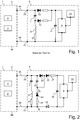
Figur 1 eine Schaltung gemäß dem Stand der Technik; -
Figur 2 eine erste Ausführungsform der erfindungsgemäßen Schaltung; -
Figur 3 eine zweite Ausführungsform der erfindungsgemäßen Schaltung; -
Figur 4 eine dritte Ausführungsform der erfindungsgemäßen Schaltung; und -
Figur 5 eine vierte Ausführungsform der erfindungsgemäßen Schaltung. - In
Figur 1 ist eine Schaltung gezeigt, wie sie auch aus den vorstehend genannten Dokumenten aus dem Stand der Technik, insbesondere derJP 5589870 B2 Figur 2 , bekannt ist. - Auf Fahrzeugseite ist eine ECU (Electronic Control Unit) 1 vorgesehen. Diese ECU hat einen Antennenbetriebsteil 2 und einen Stromversorgungsteil 3. Die ECU 1 ist außerdem mit der Fahrzeugmasse und der Bordspannungsversorgung des Kraftfahrzeugs gekoppelt. Die ECU 1 führt zwei Kabel 4A und 4B zu dem Fahrzeugtürgriff-Schaltung 5. Ein erster Kontakt 20 der Fahrzeugtürgriff-Schaltung 5 ist mit dem Kabel 4A gekoppelt, und ein zweiter Kontakt 22 der Fahrzeugtürgriff-Schaltung 5 ist mit dem Kabel 4B gekoppelt.
- Die innerhalb des Fahrzeugtürgriffes angeordnete Fahrzeugtürgriff-Schaltung 5 weist einen AntennenSerienschwingkreis mit einer Kapazität 7 und einer Induktivität 8 und eine Steuerschaltung 9 auf (der Widerstand 6 bezeichnet den ohmschen Widerstand der Wicklung der Induktivität). Es ist ersichtlich, dass für den Fall, dass an den Kontakten 20, 21 eine Gleichspannung anliegt, der Schwingkreis mit dem Kapazität 7 und der Induktivität 8 sperrt und eine Versorgung der Steuerschaltung 9 über eine Diode 10 erfolgt. Ein Pufferkondensator 11 dient der Stabilisierung der Versorgungsspannung. Wird hingegen eine Wechselspannung an die Kontakte 20, 21 angelegt, so wird der Serienschwingkreis leitend, wobei - insbesondere bei Annäherung an die Resonanzfrequenz - keine ausreichende Spannung mehr an der Steuerschaltung 9 anliegt. Die an den Abgriff zwischen dem Kondensator 7 und der Induktivität 8 angekoppelte Diode 12 ermöglicht es jedoch, die zwischen dem Kondensator 7 und der Induktivität 8 überhöhte Spannung zur Versorgung der Steuerschaltung 9 auch während des Betriebs in der Sendephase der Antenne zu nutzen.
- Der Sensor 13 ist mit der Steuerschaltung 9 gekoppelt. Es kann sich dabei um einen kapazitiven Sensor oder auch einen Tastschalter handelt. Die Steuerschaltung 9 wertet die Signale des Sensors 13 aus, um eine Betätigung am Fahrzeuggriff zu erfassen. Ein diese Erfassung anzeigendes Signal wird ebenfalls über die Leitungen 4A und 4B von der Fahrzeugtürgriff-Schaltung 5 an das Steuergerät 1 weitergeleitet und dort ausgewertet.
-
Figur 2 zeigt ein erstes Ausführungsbeispiel der erfindungsgemäßen Fahrzeugtürgriff-Schaltung 5. Auf Fahrzeugseite ist - wie im Stand der Technik - eine ECU (Electronic Control Unit) 1 mit einem Antennenbetriebsteil 2 und einem Stromversorgungsteil 3 vorgesehen. Die ECU 1 ist außerdem mit der Fahrzeugmasse und einer Bordspannungsversorgung des Kraftfahrzeugs gekoppelt. Die ECU 1 ist über zwei Kabel oder Anschlussleitungen 4A und 4B mit der Fahrzeugtürgriff-Schaltung 5 verbunden. Ein erster Kontakt 20 der Fahrzeugtürgriff-Schaltung 5 ist mit dem Kabel 4A gekoppelt, das hier die Spannungsversorgungsleitung darstellt. Ein zweiter Kontakt 22 der Fahrzeugtürgriff-Schaltung 5 ist mit dem Kabel 4B gekoppelt, das hier eine Fahrzeugtürgriff-Masse darstellt. Die Fahrzeugtürgriff-Masse des Kontakts 21 kann der Fahrzeugmasse des Steuergeräts entsprechen, kann aber auch im Potential geringfügig davon abweichen. - Der Serienschwingkreis der Fahrzeugtürgriff-Schaltung 5 mit der Kapazität 7, der Induktivität 8 und dem ohmschen Widerstand 6 ist zwischen die Kontakte 20 und 21 eingekoppelt. Parallel zu dem Serienschwingkreis ist eine Speise-Vierpolschaltung mit angekoppelter Steuerschaltung 9 geschaltet. Wiederum ist der Sensor 13 mit der Steuerschaltung 9 gekoppelt.
- Die Speise-Vierpolschaltung umfasst eine Reihenschaltung von einem ersten Gleichrichter 24 (Diode), einem ersten Kondensator 25 und einem Widerstand 28, die parallel zu dem Serienschwingkreis mit den Kontakten 20 und 21 verbunden ist. Diese Reihenschaltung weist einen zwischen dem ersten Kondensator 25 und der Kathode des ersten Gleichrichters 24 angeordneten Abgriff 29 auf. Mit dem Abgriff 29 ist die Anode eines zweiten Gleichrichters 23 verbunden. Die Kathode des zweiten Gleichrichters 23 ist über einen Strombegrenzungswiderstand 27 mit einem der beiden Spannungsversorgungsanschlüsse der Steuerschaltung 9 verbunden. Parallel zu den Spannungsversorgungsanschlüssen der Steuerschaltung 9 ist eine Puffer-Kondensator 26 geschaltet. Zwischen dem Knoten, der den ersten Kondensator 25 mit dem Kontakt 20 verbindet, und dem Knoten, der den Abgriff 29 mit der Anode des zweiten Gleichrichters verbindet, ist ein dritter Gleichrichter 22 derart eingekoppelt, dass er bei Speisung der Fahrzeugtürgriff-Schaltung 5 mit Gleichspannung in Durchlassrichtung geschaltet ist.
- Bei einer anliegenden Gleichspannung zwischen dem ersten Kontakt 20 und dem zweiten Kontakt 21 sperrt der Serienschwingkreis, und die Steuerschaltung 9 wird über die Gleichrichter 22 und 23 gespeist. Wird jedoch eine Wechselspannung in Gestalt einer (gleichspannungsfreien) Rechteckspannung mit einer sich der Schwingkreis-Resonanzfrequenz annähernden Frequenz angelegt, wird der Schwingkreis aus dem Kondensator 7 und der Induktivität 8 angeregt. Angesichts der Rechteckspannung sind jedoch zumindest die Oberwellen nicht in Resonanz mit dem Schwingkreis. Diese können über die Schaltung dieser Ausführungsform genutzt werden, um die Steuerschaltung 9 mit einer Gleichspannung zu versorgen. Der dritte Gleichrichter 22 stellt einen Verpolschutz zum Schutz der Steuerschaltung dar. Der Kondensator 25 in Kombination mit dem Gleichrichter 23 und dem Gleichrichter 24 ermöglicht es, die aus den Oberwellen resultierende Spannung zu verstärken und als Gleichspannung über den Pufferkondensator 26 an die Steuerschaltung 9 bereitzustellen. Der Kondensator 25 und die Gleichrichter 23, 24 bilden eine Spannungsverdopplungsschaltung und erzeugen aus zugeführter Wechselspannung eine betragsmäßig höhere Gleichspannung (einstufige Kaskade).
- Dies ist möglich, da keine perfekte Anpassung zwischen der Anregungsspannung und dem Schwingkreis vorliegt. Dies ist insbesondere dann der Fall, wenn eine Rechteckspannung eingespeist wird. Ansonsten kann der Schwingkreis auch gezielt fehlabgestimmt zu der Eingangsfrequenz sein, um eine ausreichende Spannungsversorgung der Steuerschaltung 9 bereitzustellen.
- Die Erfindung funktioniert also insbesondere dann, wenn die anliegende Spannung keine perfekte Sinusspannung mit einer perfekten Anpassung auf den Schwingkreis ist.
-
Figur 3 zeigt ein alternatives Ausführungsbeispiel der erfindungsgemäßen Schaltung. Auch hier umfasst die Speise-Vierpolschaltung eine Reihenschaltung eines ersten Gleichrichters 24, eines ersten Kondensator 25 und eines Widerstands 28, die parallel zu dem Serienschwingkreis mit den Kontakten 20 und 21 verbunden ist. Diese Reihenschaltung weist wiederum einen zwischen dem ersten Kondensator 25 und der Kathode des ersten Gleichrichters 24 angeordneten Abgriff 29 auf. Mit dem Abgriff 29 ist die Anode eines zweiten Gleichrichters 31 verbunden. Die Kathode des zweiten Gleichrichters 31 ist über einen Strombegrenzungswiderstand 27 mit einem der beiden Spannungsversorgungsanschlüsse der Steuerschaltung 9 verbunden. Parallel zu den Spannungsversorgungsanschlüssen der Steuerschaltung 9 ist eine Puffer-Kondensator 26 geschaltet. - Bei diesem zweiten Ausführungsbeispiel ist jedoch der dritte Gleichrichter 22, der bei Speisung der Fahrzeugtürgriff-Schaltung 5 mit Gleichspannung in Durchlassrichtung geschaltet ist, zwischen dem Knoten, der den ersten Kondensator 25 mit dem Kontakt 20 verbindet, und dem Knoten, der die Kathode des zweiten Gleichrichters 31 mit dem Strombegrenzungswiderstand 27 verbindet, eingekoppelt.
- Der Gleichrichter 22 liegt somit parallel zu einer Serienschaltung des Kondensators 25 und des Gleichrichters 31. Dies führt dazu, dass der Kondensator 25 zeitweise (während jedes zweiten Halbzyklus) einseitig potenzialfrei ist.
- In
Figur 4 ist eine Abwandlung des zweiten Ausführungsbeispiels ausFigur 3 gezeigt. Dort ist der ohmsche Widerstand 35 der Reihenschaltung zwischen den Kondensator 30 und den ersten Kontakt 20 geschaltet. Außerdem ist die Kathode des zweiten Gleichrichters 31 direkt mit dem Spannungsversorgungsanschluss der Steuerschaltung 9 verbunden, so dass der Strombegrenzungswiderstand 36 in Reihe mit dem dritten Gleichrichter 22 zwischen dem Knoten, der den ersten Kondensator 25 mit dem Kontakt 20 verbindet, und dem Knoten, der mit dem Spannungsversorgungsanschluss der Steuerschaltung 9 verbunden ist, eingekoppelt. -
Figur 5 zeigt ein viertes Ausführungsbeispiel der erfindungsgemäßen Fahrzeugtürgriff-Schaltung 5, die mit einer minimalen Anzahl von Bauelementen auskommt. Der Serienschwingkreis mit der Kapazität 7, der Induktivität 8 und dem ohmschen Widerstand 6 ist wiederum zwischen die Kontakte 20 und 21 eingekoppelt. Parallel zu dem Serienschwingkreis ist die Speise-Vierpolschaltung mit angekoppelter Steuerschaltung 9 geschaltet. Wiederum ist der Sensor 13 ist mit der Steuerschaltung 9 gekoppelt. Die Speise-Vierpolschaltung, die hier mit einer minimalen Anzahl von Bauelementen auskommt, umfasst eine Reihenschaltung des ersten Gleichrichters 24 und des ersten Kondensators 25, die hier über einen Widerstand 37 mit dem Kontakt 20 verbunden ist. Diese Reihenschaltung weist wiederum einen zwischen dem ersten Kondensator 25 und der Kathode des ersten Gleichrichters 24 angeordneten Abgriff 29 auf. Mit dem Abgriff 29 ist die Anode des zweiten Gleichrichters 31 verbunden. Die Kathode des zweiten Gleichrichters 31 ist direkt mit einem der beiden Spannungsversorgungsanschlüsse der Steuerschaltung 9 verbunden. Parallel zu den Spannungsversorgungsanschlüssen der Steuerschaltung 9 ist der Puffer-Kondensator 26 geschaltet. Der dritte Gleichrichter 22, der bei Speisung der Fahrzeugtürgriff-Schaltung 5 mit Gleichspannung in Durchlassrichtung geschaltet ist, ist zwischen dem Knoten, der den ersten Kondensator 25 mit dem Widerstand 37 verbindet, und dem Knoten, der die Kathode des zweiten Gleichrichters 31 mit dem Spannungsversorgungsanschluss der Steuerschaltung 9 verbindet, eingekoppelt. Der dem Speise-Vierpol vorgeschaltete Strombegrenzungswiderstand 37 begrenzt dem Strom sowohl im Gleichspannungsbetrieb als auch bei Wechselsignalspeisung. Bei diesem Ausführungsbeispiel umfasst der Speise-Vierpol mit dem ersten, zweiten und dritten Gleichrichter 24, 31 und 25, dem ersten und zweiten Kondensator 25 und 26 und dem einzigen Vorwiderstand 37 nur insgesamt sechs Bauelemente. - Die Dimensionierung der verschiedenen Bauteile ist auf die gewünschte Sendefrequenz sowie auch die erwarteten Betriebsspannungen abzustimmen. In sämtlichen gezeigten Ausführungsbeispielen kann das System beispielweise bei einer Frequenz von 134,2 kHz mit einer Spannung 6,8 V gespeist werden. Der erste Kondensator 25 kann beispielsweise eine Kapazität von 100 nF aufweisen. Der Pufferkondensator 26 kann beispielsweise eine Kapazität von 4,7 µF aufweisen. Die Widerstände 27, 28, 35, 36 und 37 können beispielsweise Widerstandwerte von 560 Ω haben.
Claims (9)
- Fahrzeugtürgriff, enthaltend eine Fahrzeugtürgriff-Schaltung (5), die zur Kopplung mit einem fahrzeugseitigen Steuergerät (1) ausgebildet ist, wobei die Fahrzeugtürgriff-Schaltung (5) eine Antennenschaltung (6, 7, 8) zum Abstrahlen eines zu sendenden Signals, eine Steuerschaltung (9) und wenigstens einen Betätigungssensor (13) umfasst, wobei die Steuerschaltung (9) mit dem Betätigungssensor (13) zur Erfassung einer Betätigung gekoppelt ist, wobei die Antennenschaltung (6, 7, 8) einen Serienschwingkreis mit einer Schwingkreis-Induktivität (8) und einer Schwingkreis-Kapazität (7) umfasst,
wobei die Fahrzeugtürgriff-Schaltung (5) zwei Kontakte (20, 21) aufweist zur Ankopplung an das fahrzeugseitige Steuergerät (1) über nur zwei Anschlussleitungen (4A, 4B), über die die Fahrzeugtürgriff-Schaltung (5) von dem fahrzeugseitigen Steuergerät (1) eine Versorgungsgleichspannung zur Versorgung der Steuerschaltung (9) oder ein Wechselspannungssignal zum Ansteuern der Antennenschaltung (6, 7, 8) empfangen kann,
wobei die Antennenschaltung (6, 7, 8) zwischen die beiden Kontakte (20, 21) eingekoppelt ist,
wobei die Steuerschaltung (9) zwei mit den beiden Kontakten (20, 21) gekoppelte Spannungsversorgungsanschlüsse aufweist,
dadurch gekennzeichnet,
dass zum Zwecke der Nutzung eines Teils des Wechselspannungssignals zur Spannungsversorgung der Steuerschaltung (9)zwischen die beiden Kontakte (20, 21) und parallel zu der Antennenschaltung (6, 7, 8) eine Reihenschaltung, die einen ersten Kondensator (25) mit einem in Reihe geschalteten ersten Gleichrichter (24) umfasst, geschaltet ist, wobei der erste Gleichrichter (24) in Bezug auf die Versorgungsgleichspannung in Sperrrichtung geschaltet ist, undein zwischen dem ersten Kondensator (25) und dem ersten Gleichrichter (24) angeordneter Abgriff (29) der Reihenschaltung mit einem ersten Spannungsversorgungsanschluss der Steuerschaltung (9) gekoppelt ist,wobei wenigstens ein zweiter Gleichrichter (23; 23'; 31) zwischen dem Abgriff (29) und dem ersten Spannungsversorgungsanschluss und/oder zwischen dem zweiten Spannungsversorgungsanschluss und demjenigen Knoten (30) eingekoppelt ist, der einen der beiden Kontakte (20, 21) mit der Reihenschaltung auf der Seite des ersten Gleichrichters (24) verbindet, wobei der zweite Gleichrichter (23; 23'; 31) in der gegenüber dem ersten Gleichrichter (24) entgegengesetzten Polung mit dem Abgriff (29) beziehungsweise mit dem Knoten (30) gekoppelt ist, unddass zur Einspeisung der Versorgungsgleichspannung des fahrzeugseitigen Steuergeräts (1) zwischen demjenigen Kontakt (20) der beiden Kontakte, der mit der Reihenschaltung auf der Seite des ersten Kondensators (25) verbunden ist, und dem ersten Spannungsversorgungsanschluss der Steuerschaltung (9) ein dritter Gleichrichter (22) eingekoppelt ist, wobei der dritte Gleichrichter (22) in Bezug auf die Versorgungsgleichspannung in Durchlassrichtung geschaltet ist. - Fahrzeugtürgriff nach Anspruch 1, wobei der Abgriff (29) mit dem dritten Gleichrichter (22) derart gekoppelt ist, dass der dritte Gleichrichter (22) parallel zu dem ersten Kondensator (25) geschaltet ist, wobei der zweite Gleichrichter (23; 23') zwischen dem Abgriff (29) und dem ersten Spannungsversorgungsanschluss oder zwischen dem zweiten Spannungsversorgungsanschluss und demjenigen Knoten (30) eingekoppelt ist, der einen der beiden Kontakte (20, 21) mit der Reihenschaltung auf der Seite des ersten Gleichrichters (24) verbindet.
- Fahrzeugtürgriff nach Anspruch 1, wobei der Abgriff (29) über den zweiten Gleichrichter (31) mit dem dritten Gleichrichter (22) derart gekoppelt ist, dass der dritte Gleichrichter (22) parallel zu einer Reihenschaltung des ersten Kondensators (25) und des zweiten Gleichrichters (31) geschaltet ist.
- Fahrzeugtürgriff nach einem der Ansprüche 1 bis 3, wobei die den ersten Kondensator (25) und den ersten Gleichrichter (24) umfassende Reihenschaltung einen ersten ohmschen Widerstand (28; 35) umfasst.
- Fahrzeugtürgriff nach Anspruch 4, wobei der dritte Gleichrichter (22) mit wenigstens einem zweiten ohmschen Widerstand (27; 36) in Reihe geschaltet ist.
- Fahrzeugtürgriff nach Anspruch 3, wobei ein ohmscher Widerstand (37) zwischen einem der beiden Kontakte (20) und dem die Reihenschaltung mit dem dritten Gleichrichter (22) verbindenden Knoten (38) eingekoppelt ist.
- Fahrzeugtürgriff nach einem der vorangehenden Ansprüche, wobei ein zweiter Kondensator (26) zwischen die Spannungsversorgungsanschlüsse der Steuerschaltung (9) geschaltet ist.
- Fahrzeugtürgriff nach einem der vorangehenden Ansprüche, wobei der erste Kondensator (25) eine Kapazität von 10 nF bis 500 nF hat.
- Fahrzeugtürgriff nach einem der Ansprüche 7 oder 8, wobei der zweite Kondensator (26) eine Kapazität von 0,5 µF bis 50 µF hat.
Applications Claiming Priority (2)
| Application Number | Priority Date | Filing Date | Title |
|---|---|---|---|
| DE102016106385.1A DE102016106385A1 (de) | 2016-04-07 | 2016-04-07 | Fahrzeugtürgriff mit Steuerschaltung |
| PCT/EP2017/058290 WO2017174745A1 (de) | 2016-04-07 | 2017-04-06 | Fahrzeugtürgriff mit steuerschaltung |
Publications (2)
| Publication Number | Publication Date |
|---|---|
| EP3440639A1 EP3440639A1 (de) | 2019-02-13 |
| EP3440639B1 true EP3440639B1 (de) | 2020-02-05 |
Family
ID=58632355
Family Applications (1)
| Application Number | Title | Priority Date | Filing Date |
|---|---|---|---|
| EP17719187.1A Active EP3440639B1 (de) | 2016-04-07 | 2017-04-06 | Fahrzeugtürgriff mit steuerschaltung |
Country Status (6)
| Country | Link |
|---|---|
| US (1) | US10767398B2 (de) |
| EP (1) | EP3440639B1 (de) |
| JP (1) | JP2019516884A (de) |
| CN (1) | CN108885807B (de) |
| DE (1) | DE102016106385A1 (de) |
| WO (1) | WO2017174745A1 (de) |
Family Cites Families (27)
| Publication number | Priority date | Publication date | Assignee | Title |
|---|---|---|---|---|
| GB2100075B (en) * | 1981-05-19 | 1984-07-18 | Tokyo Shibaura Electric Co | Rectifier circuit |
| EP0203262A3 (de) * | 1985-05-28 | 1987-09-30 | David Arlasky | Diebstahlsicherung für Kraftfahrzeuge |
| US4731605A (en) * | 1987-02-20 | 1988-03-15 | Nixon James E | Remote garage door opener conversion |
| GB8816774D0 (en) * | 1988-07-14 | 1988-08-17 | Bsr Int Plc | Power supplies |
| US4971549A (en) * | 1988-08-23 | 1990-11-20 | Robertshaw Controls Company | Fuel control unit for a gas furnace and method of making the same |
| JPH0628531A (ja) * | 1992-02-01 | 1994-02-04 | A I Technol:Kk | 信号発生装置 |
| CN2174533Y (zh) * | 1993-05-04 | 1994-08-17 | 扬润企业股份有限公司 | 车辆用天线式钥匙遥控装置 |
| FR2737622B1 (fr) * | 1995-08-02 | 1997-09-12 | Em Microelectronic Marin Sa | Dispositif d'interface radiofrequence pour transpondeur |
| FR2756953B1 (fr) * | 1996-12-10 | 1999-12-24 | Innovatron Ind Sa | Objet portatif telealimente pour la communication sans contact avec une borne |
| US6501192B1 (en) * | 2001-11-16 | 2002-12-31 | Eni Technology, Inc. | Three phase rectifier circuit with virtual neutral |
| WO2003050370A1 (en) * | 2001-12-10 | 2003-06-19 | Omron Co., Ltd. | Object sensor and controller |
| CA2544337A1 (en) * | 2003-11-13 | 2005-05-26 | Intier Automotive Closures Inc. | E-latch with microcontroller onboard latch and integrated backup energy |
| US7602274B2 (en) * | 2004-04-23 | 2009-10-13 | Microchip Technology Incorporated | Dynamic configuration of a radio frequency transponder |
| DE102005032379A1 (de) * | 2005-07-08 | 2007-01-11 | Conti Temic Microelectronic Gmbh | Zugangskontrollsystem für ein Kraftfahrzeug |
| JP5138327B2 (ja) * | 2006-10-06 | 2013-02-06 | 株式会社半導体エネルギー研究所 | 整流回路及び該整流回路を用いた半導体装置 |
| US8583065B2 (en) * | 2007-06-07 | 2013-11-12 | Vishay Intertechnology, Inc. | Digitally controlled antenna tuning circuit for radio frequency receivers |
| JP4998582B2 (ja) * | 2010-04-16 | 2012-08-15 | 株式会社日本自動車部品総合研究所 | 無線通信装置 |
| TW201251255A (en) * | 2010-12-27 | 2012-12-16 | Atmel Corp | Passive transponder with a charging circuit and method for generating a supply voltage for a passive transponder |
| JP5589870B2 (ja) | 2011-01-27 | 2014-09-17 | アイシン精機株式会社 | 車両用ドアハンドル装置 |
| JP5589869B2 (ja) | 2011-01-27 | 2014-09-17 | アイシン精機株式会社 | 車両用ドアハンドル装置 |
| WO2013030941A1 (ja) * | 2011-08-30 | 2013-03-07 | トヨタ自動車株式会社 | 車両の電源システム |
| RU2623093C2 (ru) * | 2012-02-24 | 2017-06-22 | Филипс Лайтинг Холдинг Б.В. | Модифицированная светодиодная лампа с шунтирующими конденсаторами, параллельными выпрямляющим диодам, для использования с балластом |
| JP5974693B2 (ja) * | 2012-07-10 | 2016-08-23 | アイシン精機株式会社 | アンテナ駆動装置 |
| WO2014028441A2 (en) * | 2012-08-13 | 2014-02-20 | Massachusetts Institute Of Technology | Multi-step, switched-capacitor rectifier and dc-dc converter circuits and related techniques |
| US9484626B2 (en) * | 2013-06-10 | 2016-11-01 | Magna Mirrors Of America, Inc. | Vehicle door handle assembly with antenna circuit |
| US9600012B2 (en) * | 2013-07-26 | 2017-03-21 | Siemens Aktiengesellschaft | Internal power supply of a device |
| CN104484932B (zh) * | 2014-12-30 | 2017-12-22 | 广州视声智能科技有限公司 | 一种门铃开锁控制电路 |
-
2016
- 2016-04-07 DE DE102016106385.1A patent/DE102016106385A1/de not_active Withdrawn
-
2017
- 2017-04-06 JP JP2018551118A patent/JP2019516884A/ja active Pending
- 2017-04-06 EP EP17719187.1A patent/EP3440639B1/de active Active
- 2017-04-06 WO PCT/EP2017/058290 patent/WO2017174745A1/de not_active Ceased
- 2017-04-06 CN CN201780020131.8A patent/CN108885807B/zh active Active
- 2017-04-06 US US16/091,016 patent/US10767398B2/en not_active Expired - Fee Related
Non-Patent Citations (1)
| Title |
|---|
| None * |
Also Published As
| Publication number | Publication date |
|---|---|
| US10767398B2 (en) | 2020-09-08 |
| EP3440639A1 (de) | 2019-02-13 |
| CN108885807B (zh) | 2021-06-18 |
| DE102016106385A1 (de) | 2017-10-12 |
| JP2019516884A (ja) | 2019-06-20 |
| CN108885807A (zh) | 2018-11-23 |
| US20190063118A1 (en) | 2019-02-28 |
| WO2017174745A1 (de) | 2017-10-12 |
Similar Documents
| Publication | Publication Date | Title |
|---|---|---|
| EP1275208B1 (de) | Anordnung zur kontaktlosen übertragung elektrischer signale bzw. energie | |
| EP0298562B1 (de) | Schaltungsanordnung zum Übertragen elektrischer Energie | |
| EP1261844B1 (de) | Anordnung zur erzeugung elektrischer energie aus einem magnetfeld | |
| DE112016004763T5 (de) | Energieempfangsvorrichtung und kontaktloses energieübertragungssystem | |
| DE102009057935B4 (de) | Einrichtung und Verfahren zur Detektion eines Umgreifens eines Handgeräts durch eine Hand | |
| EP2803143B1 (de) | Induktive energieversorgungseinrichtung | |
| DE102013012937A1 (de) | Zweimodiger Wireless-Power-Empfänger | |
| WO2002039379A1 (de) | Kontaktloser datenträger | |
| DE69801800T2 (de) | Verfahren zum Prüfen einer induktiven Resonanzschaltung | |
| EP2803142B1 (de) | Modulares datensystem mit induktiver energieübertragung | |
| DE202013105107U1 (de) | Bidirektionales drahtloses Lade-/Entladegerät mit einer Bypass-Steuerung | |
| EP2561167A1 (de) | Türaussengriff mit passive-entry-baugruppen und einer beleuchtungsbaugruppe | |
| DE102005003985B4 (de) | Detektionssensor für menschliche Körper | |
| DE102011115721B4 (de) | System zur drahtlosen Energieübertragung | |
| EP3621178B1 (de) | Wechselspannungsversorgungseinrichtung | |
| EP3824561B1 (de) | Vorrichtung für ein fahrzeug zur kontaktlosen datenübertragung | |
| DE102020118402A1 (de) | Fremdkörperdetektionsvorrichtung | |
| EP1929424B1 (de) | Mit einem transponder betätigbare schaltvorrichtung | |
| EP3440639A1 (de) | Fahrzeugtürgriff mit steuerschaltung | |
| DE4422069C1 (de) | Schaltungsanordnung zur Ansteuerung einer Hochfrequenz-Schaltdiode | |
| EP2108222B1 (de) | Vorrichtung | |
| DE102008031534B4 (de) | Transponder und Anordnung mit einem solchen Transponder | |
| DE102021119240A1 (de) | Verfahren zur Energieübertragung und Energieüberträger, Überwachungseinrichtung, Batterie und Fahrzeug | |
| DE102010062462A1 (de) | Antennensystem, Sendeanordnung und Verfahren zum Betrieb einer Sendeanordnung | |
| DE102018213181B4 (de) | Anordnung zum Messen zumindest einer Spannung bei einer Wechselspannungs-Energieübertragungsvorrichtung, deren Ausgangsanschlüsse mit einer Gleichrichterschaltung verbunden sind |
Legal Events
| Date | Code | Title | Description |
|---|---|---|---|
| STAA | Information on the status of an ep patent application or granted ep patent |
Free format text: STATUS: UNKNOWN |
|
| STAA | Information on the status of an ep patent application or granted ep patent |
Free format text: STATUS: THE INTERNATIONAL PUBLICATION HAS BEEN MADE |
|
| PUAI | Public reference made under article 153(3) epc to a published international application that has entered the european phase |
Free format text: ORIGINAL CODE: 0009012 |
|
| STAA | Information on the status of an ep patent application or granted ep patent |
Free format text: STATUS: REQUEST FOR EXAMINATION WAS MADE |
|
| 17P | Request for examination filed |
Effective date: 20181107 |
|
| AK | Designated contracting states |
Kind code of ref document: A1 Designated state(s): AL AT BE BG CH CY CZ DE DK EE ES FI FR GB GR HR HU IE IS IT LI LT LU LV MC MK MT NL NO PL PT RO RS SE SI SK SM TR |
|
| AX | Request for extension of the european patent |
Extension state: BA ME |
|
| DAV | Request for validation of the european patent (deleted) | ||
| DAX | Request for extension of the european patent (deleted) | ||
| GRAP | Despatch of communication of intention to grant a patent |
Free format text: ORIGINAL CODE: EPIDOSNIGR1 |
|
| STAA | Information on the status of an ep patent application or granted ep patent |
Free format text: STATUS: GRANT OF PATENT IS INTENDED |
|
| INTG | Intention to grant announced |
Effective date: 20190925 |
|
| GRAS | Grant fee paid |
Free format text: ORIGINAL CODE: EPIDOSNIGR3 |
|
| GRAA | (expected) grant |
Free format text: ORIGINAL CODE: 0009210 |
|
| STAA | Information on the status of an ep patent application or granted ep patent |
Free format text: STATUS: THE PATENT HAS BEEN GRANTED |
|
| AK | Designated contracting states |
Kind code of ref document: B1 Designated state(s): AL AT BE BG CH CY CZ DE DK EE ES FI FR GB GR HR HU IE IS IT LI LT LU LV MC MK MT NL NO PL PT RO RS SE SI SK SM TR |
|
| REG | Reference to a national code |
Ref country code: GB Ref legal event code: FG4D Free format text: NOT ENGLISH |
|
| REG | Reference to a national code |
Ref country code: AT Ref legal event code: REF Ref document number: 1230419 Country of ref document: AT Kind code of ref document: T Effective date: 20200215 |
|
| REG | Reference to a national code |
Ref country code: DE Ref legal event code: R096 Ref document number: 502017003711 Country of ref document: DE |
|
| REG | Reference to a national code |
Ref country code: IE Ref legal event code: FG4D Free format text: LANGUAGE OF EP DOCUMENT: GERMAN |
|
| REG | Reference to a national code |
Ref country code: CH Ref legal event code: EP |
|
| REG | Reference to a national code |
Ref country code: NL Ref legal event code: MP Effective date: 20200205 |
|
| PG25 | Lapsed in a contracting state [announced via postgrant information from national office to epo] |
Ref country code: FI Free format text: LAPSE BECAUSE OF FAILURE TO SUBMIT A TRANSLATION OF THE DESCRIPTION OR TO PAY THE FEE WITHIN THE PRESCRIBED TIME-LIMIT Effective date: 20200205 Ref country code: NO Free format text: LAPSE BECAUSE OF FAILURE TO SUBMIT A TRANSLATION OF THE DESCRIPTION OR TO PAY THE FEE WITHIN THE PRESCRIBED TIME-LIMIT Effective date: 20200505 Ref country code: RS Free format text: LAPSE BECAUSE OF FAILURE TO SUBMIT A TRANSLATION OF THE DESCRIPTION OR TO PAY THE FEE WITHIN THE PRESCRIBED TIME-LIMIT Effective date: 20200205 Ref country code: PT Free format text: LAPSE BECAUSE OF FAILURE TO SUBMIT A TRANSLATION OF THE DESCRIPTION OR TO PAY THE FEE WITHIN THE PRESCRIBED TIME-LIMIT Effective date: 20200628 |
|
| PGFP | Annual fee paid to national office [announced via postgrant information from national office to epo] |
Ref country code: FR Payment date: 20200421 Year of fee payment: 4 |
|
| REG | Reference to a national code |
Ref country code: LT Ref legal event code: MG4D |
|
| PG25 | Lapsed in a contracting state [announced via postgrant information from national office to epo] |
Ref country code: BG Free format text: LAPSE BECAUSE OF FAILURE TO SUBMIT A TRANSLATION OF THE DESCRIPTION OR TO PAY THE FEE WITHIN THE PRESCRIBED TIME-LIMIT Effective date: 20200505 Ref country code: GR Free format text: LAPSE BECAUSE OF FAILURE TO SUBMIT A TRANSLATION OF THE DESCRIPTION OR TO PAY THE FEE WITHIN THE PRESCRIBED TIME-LIMIT Effective date: 20200506 Ref country code: SE Free format text: LAPSE BECAUSE OF FAILURE TO SUBMIT A TRANSLATION OF THE DESCRIPTION OR TO PAY THE FEE WITHIN THE PRESCRIBED TIME-LIMIT Effective date: 20200205 Ref country code: IS Free format text: LAPSE BECAUSE OF FAILURE TO SUBMIT A TRANSLATION OF THE DESCRIPTION OR TO PAY THE FEE WITHIN THE PRESCRIBED TIME-LIMIT Effective date: 20200605 Ref country code: LV Free format text: LAPSE BECAUSE OF FAILURE TO SUBMIT A TRANSLATION OF THE DESCRIPTION OR TO PAY THE FEE WITHIN THE PRESCRIBED TIME-LIMIT Effective date: 20200205 Ref country code: HR Free format text: LAPSE BECAUSE OF FAILURE TO SUBMIT A TRANSLATION OF THE DESCRIPTION OR TO PAY THE FEE WITHIN THE PRESCRIBED TIME-LIMIT Effective date: 20200205 |
|
| PG25 | Lapsed in a contracting state [announced via postgrant information from national office to epo] |
Ref country code: NL Free format text: LAPSE BECAUSE OF FAILURE TO SUBMIT A TRANSLATION OF THE DESCRIPTION OR TO PAY THE FEE WITHIN THE PRESCRIBED TIME-LIMIT Effective date: 20200205 |
|
| PG25 | Lapsed in a contracting state [announced via postgrant information from national office to epo] |
Ref country code: DK Free format text: LAPSE BECAUSE OF FAILURE TO SUBMIT A TRANSLATION OF THE DESCRIPTION OR TO PAY THE FEE WITHIN THE PRESCRIBED TIME-LIMIT Effective date: 20200205 Ref country code: LT Free format text: LAPSE BECAUSE OF FAILURE TO SUBMIT A TRANSLATION OF THE DESCRIPTION OR TO PAY THE FEE WITHIN THE PRESCRIBED TIME-LIMIT Effective date: 20200205 Ref country code: ES Free format text: LAPSE BECAUSE OF FAILURE TO SUBMIT A TRANSLATION OF THE DESCRIPTION OR TO PAY THE FEE WITHIN THE PRESCRIBED TIME-LIMIT Effective date: 20200205 Ref country code: CZ Free format text: LAPSE BECAUSE OF FAILURE TO SUBMIT A TRANSLATION OF THE DESCRIPTION OR TO PAY THE FEE WITHIN THE PRESCRIBED TIME-LIMIT Effective date: 20200205 Ref country code: SK Free format text: LAPSE BECAUSE OF FAILURE TO SUBMIT A TRANSLATION OF THE DESCRIPTION OR TO PAY THE FEE WITHIN THE PRESCRIBED TIME-LIMIT Effective date: 20200205 Ref country code: RO Free format text: LAPSE BECAUSE OF FAILURE TO SUBMIT A TRANSLATION OF THE DESCRIPTION OR TO PAY THE FEE WITHIN THE PRESCRIBED TIME-LIMIT Effective date: 20200205 Ref country code: SM Free format text: LAPSE BECAUSE OF FAILURE TO SUBMIT A TRANSLATION OF THE DESCRIPTION OR TO PAY THE FEE WITHIN THE PRESCRIBED TIME-LIMIT Effective date: 20200205 Ref country code: EE Free format text: LAPSE BECAUSE OF FAILURE TO SUBMIT A TRANSLATION OF THE DESCRIPTION OR TO PAY THE FEE WITHIN THE PRESCRIBED TIME-LIMIT Effective date: 20200205 |
|
| REG | Reference to a national code |
Ref country code: DE Ref legal event code: R097 Ref document number: 502017003711 Country of ref document: DE |
|
| PG25 | Lapsed in a contracting state [announced via postgrant information from national office to epo] |
Ref country code: MC Free format text: LAPSE BECAUSE OF FAILURE TO SUBMIT A TRANSLATION OF THE DESCRIPTION OR TO PAY THE FEE WITHIN THE PRESCRIBED TIME-LIMIT Effective date: 20200205 |
|
| REG | Reference to a national code |
Ref country code: CH Ref legal event code: PL |
|
| PLBE | No opposition filed within time limit |
Free format text: ORIGINAL CODE: 0009261 |
|
| STAA | Information on the status of an ep patent application or granted ep patent |
Free format text: STATUS: NO OPPOSITION FILED WITHIN TIME LIMIT |
|
| 26N | No opposition filed |
Effective date: 20201106 |
|
| PG25 | Lapsed in a contracting state [announced via postgrant information from national office to epo] |
Ref country code: CH Free format text: LAPSE BECAUSE OF NON-PAYMENT OF DUE FEES Effective date: 20200430 Ref country code: IT Free format text: LAPSE BECAUSE OF FAILURE TO SUBMIT A TRANSLATION OF THE DESCRIPTION OR TO PAY THE FEE WITHIN THE PRESCRIBED TIME-LIMIT Effective date: 20200205 Ref country code: LU Free format text: LAPSE BECAUSE OF NON-PAYMENT OF DUE FEES Effective date: 20200406 Ref country code: LI Free format text: LAPSE BECAUSE OF NON-PAYMENT OF DUE FEES Effective date: 20200430 |
|
| REG | Reference to a national code |
Ref country code: BE Ref legal event code: MM Effective date: 20200430 |
|
| PG25 | Lapsed in a contracting state [announced via postgrant information from national office to epo] |
Ref country code: SI Free format text: LAPSE BECAUSE OF FAILURE TO SUBMIT A TRANSLATION OF THE DESCRIPTION OR TO PAY THE FEE WITHIN THE PRESCRIBED TIME-LIMIT Effective date: 20200205 Ref country code: BE Free format text: LAPSE BECAUSE OF NON-PAYMENT OF DUE FEES Effective date: 20200430 Ref country code: PL Free format text: LAPSE BECAUSE OF FAILURE TO SUBMIT A TRANSLATION OF THE DESCRIPTION OR TO PAY THE FEE WITHIN THE PRESCRIBED TIME-LIMIT Effective date: 20200205 |
|
| PG25 | Lapsed in a contracting state [announced via postgrant information from national office to epo] |
Ref country code: IE Free format text: LAPSE BECAUSE OF NON-PAYMENT OF DUE FEES Effective date: 20200406 |
|
| GBPC | Gb: european patent ceased through non-payment of renewal fee |
Effective date: 20210406 |
|
| PG25 | Lapsed in a contracting state [announced via postgrant information from national office to epo] |
Ref country code: FR Free format text: LAPSE BECAUSE OF NON-PAYMENT OF DUE FEES Effective date: 20210430 Ref country code: GB Free format text: LAPSE BECAUSE OF NON-PAYMENT OF DUE FEES Effective date: 20210406 |
|
| PG25 | Lapsed in a contracting state [announced via postgrant information from national office to epo] |
Ref country code: TR Free format text: LAPSE BECAUSE OF FAILURE TO SUBMIT A TRANSLATION OF THE DESCRIPTION OR TO PAY THE FEE WITHIN THE PRESCRIBED TIME-LIMIT Effective date: 20200205 Ref country code: MT Free format text: LAPSE BECAUSE OF FAILURE TO SUBMIT A TRANSLATION OF THE DESCRIPTION OR TO PAY THE FEE WITHIN THE PRESCRIBED TIME-LIMIT Effective date: 20200205 Ref country code: CY Free format text: LAPSE BECAUSE OF FAILURE TO SUBMIT A TRANSLATION OF THE DESCRIPTION OR TO PAY THE FEE WITHIN THE PRESCRIBED TIME-LIMIT Effective date: 20200205 |
|
| PG25 | Lapsed in a contracting state [announced via postgrant information from national office to epo] |
Ref country code: MK Free format text: LAPSE BECAUSE OF FAILURE TO SUBMIT A TRANSLATION OF THE DESCRIPTION OR TO PAY THE FEE WITHIN THE PRESCRIBED TIME-LIMIT Effective date: 20200205 Ref country code: AL Free format text: LAPSE BECAUSE OF FAILURE TO SUBMIT A TRANSLATION OF THE DESCRIPTION OR TO PAY THE FEE WITHIN THE PRESCRIBED TIME-LIMIT Effective date: 20200205 |
|
| P01 | Opt-out of the competence of the unified patent court (upc) registered |
Effective date: 20230507 |
|
| REG | Reference to a national code |
Ref country code: AT Ref legal event code: MM01 Ref document number: 1230419 Country of ref document: AT Kind code of ref document: T Effective date: 20220406 |
|
| PG25 | Lapsed in a contracting state [announced via postgrant information from national office to epo] |
Ref country code: AT Free format text: LAPSE BECAUSE OF NON-PAYMENT OF DUE FEES Effective date: 20220406 |
|
| PGFP | Annual fee paid to national office [announced via postgrant information from national office to epo] |
Ref country code: DE Payment date: 20250430 Year of fee payment: 9 |