EP3438762A2 - Timepiece oscillator having flexible guides with wide angular travel - Google Patents
Timepiece oscillator having flexible guides with wide angular travel Download PDFInfo
- Publication number
- EP3438762A2 EP3438762A2 EP18185138.7A EP18185138A EP3438762A2 EP 3438762 A2 EP3438762 A2 EP 3438762A2 EP 18185138 A EP18185138 A EP 18185138A EP 3438762 A2 EP3438762 A2 EP 3438762A2
- Authority
- EP
- European Patent Office
- Prior art keywords
- blade
- blades
- plane
- oscillation
- flexible
- Prior art date
- Legal status (The legal status is an assumption and is not a legal conclusion. Google has not performed a legal analysis and makes no representation as to the accuracy of the status listed.)
- Pending
Links
Images


Classifications
-
- G—PHYSICS
- G04—HOROLOGY
- G04B—MECHANICALLY-DRIVEN CLOCKS OR WATCHES; MECHANICAL PARTS OF CLOCKS OR WATCHES IN GENERAL; TIME PIECES USING THE POSITION OF THE SUN, MOON OR STARS
- G04B31/00—Bearings; Point suspensions or counter-point suspensions; Pivot bearings; Single parts therefor
-
- G—PHYSICS
- G04—HOROLOGY
- G04B—MECHANICALLY-DRIVEN CLOCKS OR WATCHES; MECHANICAL PARTS OF CLOCKS OR WATCHES IN GENERAL; TIME PIECES USING THE POSITION OF THE SUN, MOON OR STARS
- G04B17/00—Mechanisms for stabilising frequency
- G04B17/04—Oscillators acting by spring tension
- G04B17/045—Oscillators acting by spring tension with oscillating blade springs
-
- B—PERFORMING OPERATIONS; TRANSPORTING
- B81—MICROSTRUCTURAL TECHNOLOGY
- B81B—MICROSTRUCTURAL DEVICES OR SYSTEMS, e.g. MICROMECHANICAL DEVICES
- B81B3/00—Devices comprising flexible or deformable elements, e.g. comprising elastic tongues or membranes
- B81B3/0035—Constitution or structural means for controlling the movement of the flexible or deformable elements
- B81B3/004—Angular deflection
- B81B3/0045—Improve properties related to angular swinging, e.g. control resonance frequency
-
- G—PHYSICS
- G04—HOROLOGY
- G04B—MECHANICALLY-DRIVEN CLOCKS OR WATCHES; MECHANICAL PARTS OF CLOCKS OR WATCHES IN GENERAL; TIME PIECES USING THE POSITION OF THE SUN, MOON OR STARS
- G04B31/00—Bearings; Point suspensions or counter-point suspensions; Pivot bearings; Single parts therefor
- G04B31/02—Shock-damping bearings
Definitions
- the invention relates to a clockwork mechanical oscillator comprising, between a rigid support member and a solid inertial element, a flexible guide with at least two first flexible blades which support said massive inertial element and are arranged to return it to a rest position.
- said solid inertial element being arranged to oscillate angularly along a plane of oscillation around said rest position, said two first flexible blades not touching each other and their projections on said oscillation plane intersecting, in the rest position, a point of intersection, in the immediate vicinity of which or through which the axis of rotation of said solid inertial element perpendicular to said plane of oscillation passes, and the recesses of said first flexible blades with said rigid support element and said massive inertial element defining at least two directions of blades parallel to said plane of oscillation.
- the invention also relates to a watch movement comprising at least one such mechanical oscillator.
- the invention also relates to a watch comprising such a clockwork movement.
- the invention relates to the field of mechanical clockwork oscillators comprising flexible blade guides providing the functions of holding and recall of moving elements.
- flexible guides particularly with flexible blades, in mechanical clock oscillators
- methods of production such as "MEMS", “LIGA” or similar, of micro-machinable materials, such as silicon and its oxides, which allow a very reproducible manufacture of components that have constant elastic characteristics over time and a high insensitivity to external agents such as temperature and humidity.
- Flexible guide pins as described in the applications EP1419039 or EP16155039 of the same depositor, allow in particular to replace the pivot of a conventional balance wheel, and the spiral spring which is usually associated. The elimination of the friction of pivots makes it possible to increase substantially the quality factor of an oscillator.
- the flexible guide pins generally have a small angular travel, of the order of 10 ° to 20 °, which is very low compared to the usual amplitude of 300 ° of a balance-spring, and which not allow their direct combination with conventional exhaust mechanisms, including conventional stoppers such as a Swiss anchor or the like, which require a large angular stroke to ensure their proper operation.
- the document EP3035127A1 in the name of the same applicant SWATCH GROUP RESEARCH & DEVELOPMENT Ltd describes a watch oscillator comprising a time base with at least one resonator constituted by a tuning fork which comprises at least two oscillating mobile parts, said movable parts being fixed to a connecting element , which comprises said oscillator, by flexible elements whose geometry determines a virtual pivot axis of position determined with respect to said connecting element, about which virtual pivot axis oscillates said respective moving part, whose center of mass is merged into position resting with said respective virtual pivot axis.
- said flexible elements consist of crossed elastic blades and extending at a distance from one another in two parallel planes, and whose projections of the directions on one of said parallel planes intersect at the same level.
- said virtual pivot axis, said movable part considered.
- the document US3628781A in the name of GRIB describes a tuning fork, in the form of a double cantilevered structure, to allow an increased rotational movement of a pair of moving elements, relative to a fixed reference plane
- a tuning fork in the form of a double cantilevered structure, to allow an increased rotational movement of a pair of moving elements, relative to a fixed reference plane
- a first resiliently-deformable body having at least two elastically-like elongated flexible portions, the ends of each of said flexible portions respectively being secured to enlarged rigid portions of said member, the first of said rigid portions being fixed to define a reference plane and the second being supported elastically to have an increased rotational movement with respect to the first, a second deformable body elastically substantially identical to the first deformable body resiliently, and means for rigidly securing the first of said respective rigid portions of said elastically deformable bodies in spaced relation to provide a tuning fork structure in which each of the tuning fork teeth comprises the free end of one of said elastic
- the document EP3130966A1 in the name of ETA Manufacture Horlogère Suisse describes a mechanical watchmaking movement that includes at least one barrel, a set of gear wheels driven at one end by the barrel, and a mechanism of escape of a local oscillator with a resonator in the form of a balance-spring and a feedback system of the watch movement.
- the exhaust mechanism is driven to another end of the set of gear wheels.
- the feedback system includes at least one accurate reference oscillator, combined with a step comparator for comparing the operation of the two oscillators, and a local oscillator resonator tuning mechanism for slowing or accelerating the resonator based on the oscillator. a result of the comparison in the walking comparator.
- the document CH709536A2 in the name of ETA Manufacture Horlogère Suisse describes a watchmaking mechanism comprising, mounted mobile, at least pivotally relative to a plate, an escape wheel arranged to receive a motor torque via a train, and a first oscillator comprising a first rigid structure connected to said plate by first elastic return means.
- This regulator mechanism comprises a second oscillator comprising a second rigid structure connected to said first rigid structure by second elastic return means, and which comprises guide means arranged to cooperate with complementary guiding means that comprises said escape wheel, synchronizing said first oscillator and said second oscillator with said wheel.
- the invention proposes to develop a mechanical oscillator with flexible guides, whose angular travel is compatible with existing exhaust mechanisms, and whose flexible guides behave regularly regardless of their deformation.
- the invention relates to a mechanical oscillator according to claim 1.
- the invention also relates to a watch movement comprising at least one such mechanical oscillator.
- the invention also relates to a watch comprising such a clockwork movement.
- the invention relates to a mechanical clock oscillator 100, comprising at least one rigid support element 4 fixed directly or indirectly to a plate 900, and a solid inertial element 5.
- This oscillator 100 comprises, between the rigid support element 4 and the solid inertial element 5, a flexible guide mechanism 200.
- This flexible guide mechanism comprises at least two first flexible blades 31, 32, which support the solid inertial element 5 and are arranged to return it to a rest position.
- This massive inertial element 5 is arranged to oscillate angularly according to a plane of oscillation around this rest position.
- the first two flexible blades 31 and 32 do not touch each other, and, in the rest position, their projections on the plane of oscillation intersect at a point of intersection P, in the immediate vicinity of which or through which the axis of rotation passes.
- the massive inertial element 5 perpendicular to the plane of oscillation. All the geometric elements described below mean, unless otherwise stated, as considered in the rest position of the oscillator stopped.
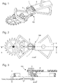
- FIGS. 1 to 4 illustrate a first variant with a rigid support element 4 and a massive inertial element connected by two first flexible blades 31, 32.
- the embedding of the first flexible blades 31, 32, with the rigid support element 4 and the solid inertial element 5 define at least two directions of blades DL1, DL2, which are parallel to the plane of oscillation and which are in projection on the plane of oscillation, an angle at the apex ⁇ .
- the value of the ratio D / L is between 0 and 1, and the apex angle ⁇ is less than or equal to 70 °.
- both the angle at the apex ⁇ is less than or equal to 60 °, and, for each first flexible blade 31, 32, the embedding ratio D1 / L1, D2 / L2 is between 0.15 and 0.85, terminals included.
- the center of mass of the oscillator 100 in its rest position is distant from the crossover point P a difference ⁇ which is between 10% and 20% of the total length L of the projection, on the plane of oscillation, of the blade 31, 32. More particularly, the difference ⁇ is between 12% and 18% of the total length L of the projection, on the plane of oscillation, of the blade 31, 32.
- the first blades 31, 32, and their recesses together define a pivot 1 which, in projection on the plane of oscillation, is symmetrical with respect to an axis of symmetry AA passing through the crossing point P.
- the center of mass of the massive inertial element 5 is located on the axis of symmetry AA of the pivot 1. In projection, this center of mass can be confused or not with the crossover point P.
- the center of mass of the massive inertial element 5 is situated at a non-zero distance from the point of intersection P corresponding to the axis of rotation of the massive inertial element 5, as visible on the Figures 2 to 4 .
- the center of mass of the massive inertial element 5 is located on the axis of symmetry AA of the pivot 1, and is situated at a non-zero distance from the crossover point P of which is between 0.1 times and 0.2 times the total length L of the projection, on the plane of oscillation, of the blade 31, 32.
- the first blades 31 and 32 are straight blades.
- the apex angle ⁇ is less than or equal to 50 °, or is less than or equal to 40 °, or less than or equal to 35 °, or even less than or equal to 30 °.
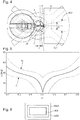
- the embedding ratio D1 / L1, D2 / L2 is between 0.15 and 0.49, including terminals, or between 0.51 and 0.85, including terminals, as visible on the figure 5 .
- the apex angle ⁇ is less than or equal to 50 °
- the embedding ratio D1 / L1, D2 / L2 is between 0.25 and 0.75, inclusive.
- the apex angle ⁇ is less than or equal to 40 °
- the embedding ratio D1 / L1, D2 / L2 is between 0.30 and 0.70, inclusive.
- the apex angle ⁇ is less than or equal to 35 °
- the embedding ratio D1 / L1, D2 / L2 is between 0.40 and 0.60, including terminals.
- the first flexible blades 31 and 32 have the same length L, and the same distance D.
- these first flexible blades 31 and 32 are identical.
- FIGS. 6 to 8 illustrate a second variant of mechanical oscillator 100, wherein the rigid support element 4 is also movable, directly or indirectly with respect to a fixed structure that this oscillator 100 comprises, and is carried by a third rigid element 6, via two second flexible blades 33, 34, arranged similarly to the first flexible blades 31, 32.
- the projections of the first flexible blades 31, 32, and second flexible blades 33, 34, on the oscillation plane intersect at the same crossover point P.
- the projections of the first flexible blades 31, 32, and second flexible blades 33, 34, on the oscillation plane. intersect at two distinct points both located on the axis of symmetry AA of the pivot 1, when the pivot 1 is symmetrical with respect to the axis of symmetry AA.
- the embedding of the second flexible blades 33, 34, with the rigid support element 4 and the third rigid element 6, define two directions of blades parallel to the plane of oscillation and forming between them, in projection on the plane of oscillation, an angle at the apex of the same bisector as the angle ⁇ at the top that the first flexible blades 31, 32. More particularly, these two directions of the second flexible blades 33, 34 have the same angle at the top ⁇ as the first flexible blades 31, 32.
- the second flexible blades 33, 34 are identical to the first flexible blades 31, 32, as in the non-limiting example of the figures.
- the center of mass of the massive inertial element 5 is located on the axis of symmetry AA of the pivot 1.
- both the mass center of the massive inertial element 5 and the center of mass of the rigid support element 4 are located on the axis of symmetry AA of the pivot 1. More particularly, the projections of the center of mass of the massive inertial element 5 and the center of mass of the rigid support element 4, on the axis of symmetry AA of the pivot 1, are confused.
- a particular configuration illustrated by the figures for such superposed pivots is that where the projections of the first flexible blades 31, 32, and second flexible blades 33, 34, on the oscillation plane intersect at the same point of intersection P, which also corresponds to the projection of the center of mass of the massive inertial element 5, or at least which is as close as possible to it. More particularly, this same point also corresponds to the projection of the center of mass of the rigid support element 4. More particularly, this same point also corresponds to the projection of the center of mass of the entire oscillator 100.
- the mass center of the massive inertial element 5 is located, in projection on the plane of oscillation, on the axis of symmetry AA of the pivot 1 and at a non-zero distance from the point of intersection corresponding to the axis of rotation of the rigid support element 4 which non-zero distance is between 0.1 times and 0.2 times the total length L of the projection, on the plane of oscillation, of the blade 31, 32.
- the center of mass of the rigid support element 4 is located, in projection on the plane of oscillation, on the axis of symmetry AA of the pivot 1 and at a non-zero distance from the crossing point P corresponding to the axis of rotation of the massive inertial element 5.
- this non-zero distance is between 0.1 times and 0.2 times the total length L of the projecting, on the plane of oscillation, the blade 33, 34.
- the center of mass of the rigid support element 4 is located, in projection on the plane of oscillation, on the axis of symmetry AA of the pivot 1 and at a non-zero distance from the point of intersection corresponding to the axis of rotation of the rigid support element 4 which non-zero distance is between 0.1 times and 0.2 times the total length L of the projection, on the plane of oscillation, of the blade 31, 32.
- the center of mass of the rigid support member 4 is located on the axis of symmetry AA of the pivot 1 and the non-zero distance of the crossover point P which is between 0.1 times and 0.2 times the total length L of the projection, on the plane of oscillation, of the blade 33, 34.
- the massive inertial element 5 is elongate in the direction of the axis of symmetry AA of the pivot 1, when the pivot 1 is symmetrical with respect to the axis of symmetry AA.
- the inertial element 5 comprises a base on which is fixed a traditional long-arm balancer provided with sections of serge or flyweights in an arc.
- the objective is to minimize the influence of external angular accelerations around the axis of symmetry of the pivot, because the blades have a low rigidity in rotation around this axis because of the small angle ⁇ .
- the invention lends itself well to a monolithic execution of the blades and the solid components they join, made of micro-machinable material or at least partially amorphous, with an implementation by "MEMS" or "LIGA” method or the like.
- the oscillator 100 is advantageously thermally compensated by adding silicon dioxide to flexible silicon strips.
- the blades can be assembled, for example embedded in grooves, or other.
- the illustrated variants comprise all pivot axes, blade crossings, and mass centers, coplanar, which is a special case that is advantageous, but not limiting.
- each of the elementary blades has an aspect ratio limited to a threshold value.
- the aspect ratio of each elementary plate is reduced to find the optimum of isochronism and insensitivity to the positions.
- the oscillator 100 comprises a first number N1 of first blades called primary blades 31 extending in a first blade direction DL1, and a second number N2 of first secondary blades 32 extending in a second blade direction DL2 the first number N1 and the second number N2 each being greater than or equal to two.
- the first number N1 is equal to the second number N2.
- the oscillator 100 comprises at least one pair formed of a primary blade 31 extending in a first blade direction DL1, and a secondary blade 32 extending in a second blade direction DL2. And, in each pair, the primary blade 31 is identical to the secondary blade 32 in the orientation.
- the oscillator 100 has only pairs each formed of a primary blade 31 extending in a first blade direction DL1, and a secondary blade 32 extending in a second blade direction DL2 and in each pair, the primary blade 31 is identical to the secondary blade 32 in the orientation.
- the oscillator 100 comprises at least one group of blades formed of a primary blade 31 extending in a first blade direction DL1, and a plurality of secondary blades 32 extending in a second direction DL2 blade direction. And, in this case, in each group of blades, the elastic behavior of the primary blade 31 is identical to the elastic behavior resulting from the accumulation of the plurality of secondary blades 32 to the orientation.
- the invention also relates to a watch movement 1000 comprising at least one such mechanical oscillator 100.
- the invention also relates to a watch 2000 comprising at least one such watch movement 1000.
- DRIE Deep Reactive Ion Etching
- Standard methods of manufacturing by DRIE etching of silicon do not yet make it easy to manufacture a monolithic pivot having more than two distinct levels. It is therefore easier to manufacture separate parts which are then assembled.
- the sensitivity to assembly errors requires a precision greater than one micrometer, to obtain the optimal properties of isochronism and / or insensitivity to the positions. In order to solve this problem, it is necessary to adopt a manufacturing strategy which is described below.
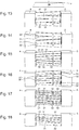
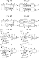
- the invention proposes to dividing the flexible guide, or pivot, into subunits composed of two-blade pivots, for example an upper subunit and a lower subunit, in the case of a flexible guide comprising four blades, as visible on the figure 19 , with four alternate blades, which is broken down into two subunits of two-blade pivots.
- the Figures 21 and 22 illustrate a similar decomposition in the case of framed blades rather than alternate blades.
- Each subunit is manufactured by two-level DRIE etching (SOI wafer attacked from above and below) to ensure sufficient alignment accuracy.
- the upper subunit is then assembled to the lower subunit.
- This assembly can be performed by any conventional method: alignment pinning and screwing, or bonding, or "wafer fusion bonding", or solder, or solder, or any other method known to those skilled in the art.
- the mechanism comprises at least one translation table, whose free movement can absorb the disagreement between the two rotations of separate axes. At least one of the translation tables must be sufficiently flexible so that the movement mismatch does not degrade the isochronism. In the case where two identical translation tables are introduced, as shown in FIG. figure 23 they must be sufficiently flexible so that the motion discrepancy does not degrade the isochronism, and sufficiently rigid so that the position of the pivot is well determined.
- the flexible guiding mechanism 200 comprises, superimposed on one another, at least one upper stage 28 and at least one lower stage 29.
- the upper subunit comprises an upper stage 28, which comprises, between an upper support 48 and an upper inertial element 58, at least one upper primary blade 318 extending in a first upper blade direction DL1S and an upper secondary blade 328. extending in a second upper blade direction DL2S, intersected in projection at an upper crossing point PS.
- the lower subunit comprises a lower stage 29, which comprises, between a lower support 49 and a lower inertial element 59, at least one lower primary blade 319 extending in a first lower blade direction DL1I and a lower secondary blade 329. extending in a second lower blade direction DL2I crossed in projection at a lower crossover point PI, at rest at the upper crossover point PS of a difference ⁇ .
- At least the upper stage 28 or the lower stage 29 comprises, between the plate 900 and the upper support 48, or respectively the lower support 49, an upper translation table 308, or respectively a lower translation table 309, which has at least one elastic connection which allows the translation along one or two axes of freedom in the plane of oscillation, and whose translational stiffness along these two axes is less than that of each flexible blade 31, 32, 333, 34, 318, 319, 328, 329, which comprises the flexible guide mechanism 200.
- the upper directions DL1S and DL2S of the upper stage 28 are identical to the lower directions DL1I and DL2I of the lower stage 29. Preferably, they have the same bisectors.
- the point P through which the axis of rotation of the inertial element 5 passes is situated between the upper point of intersection PS and the lower point of intersection P1, exactly in the middle if the flexible guide mechanism 200 comprises two tables. higher translations 308 and lower 309 which are identical.
- this point P is located exactly on the lower crossing point PI if the lower stage 29 does not have a translation table, or on the upper point of intersection PS if the upper stage 28 does not have a table translation.
- the oscillator 100 comprises, for each flexible guide mechanism 200 that it comprises, a massive inertial element 5 is unique. More particularly, the flexible guide mechanism 200 is unique, and the solid inertial element 5 is unique.
- translation tables 308 and 309 illustrated by the figures is not limiting. These translation tables 308 and 309 can also be between the inertial element 5 and the recesses of the inertial element side.
- the combination of the tables in translation, along the X axis and along the Y axis must be more flexible than the flexible pivot according to the same axes. This rule is valid regardless of the number of stages, the cumulation due to the combination of all the tables, in translation, along the X axis and along the Y axis, must be more flexible than the flexible pivot.
- the elastic connection of the upper translation table 308, or respectively of the lower translation table 309, along one or two axes of freedom in the oscillation plane, is thus preferably an elastic connection along these axes X and Y.
- the upper stage 28 and the lower stage 29 each comprise, between the plate 900 and the upper support 48, and respectively the lower support 49, an upper translation table 308, or respectively a lower translation table 309, comprising at least one elastic connection in one or two axes of freedom in the plane of oscillation, and whose stiffness is less than that of each flexible blade.
- An alternative is to use two different translation tables, the first being flexible so that the movement mismatch does not degrade the isochronism, and the second is rigid to ensure the positioning of the pivot.
- one stage may comprise a translation table, and the other stage may have a rigid attachment
- the upper inertial element 58 and the lower inertial element 59 constitute all or part of the massive inertial element 5, and are rigidly connected, directly or indirectly, to each other.
- the upper support 48 and the lower support 49 are connected, as appropriate, directly or through an upper translation table 308, or respectively a lower translation table 309, to an upper rigid part 480, respectively a lower rigid portion 490, which are rigidly connected to the rigid support member 4, or to the plate 900.
- An upper translation table 308 comprises, between the upper support 48 and an upper intermediate mass 68, first flexible elastic links 78 extending in the direction X, and, between the upper intermediate mass 68 and the upper rigid portion 480, second flexible elastic links 88 extending in the direction Y.
- a lower translation table 309 comprises, between the lower support 49 and a lower intermediate mass 69, first flexible elastic links 79 extending in the direction X and, between the lower intermediate mass 69 and the lower rigid portion 490, second resilient flexible links 89 extending in the Y direction.
- each translation table contributes to the protection of the mechanism against strong accelerations, during a fall or percussion for example.
- This particular arrangement with at least one translation table makes it possible, in short, to guarantee the alignment between the upper and lower stages, and to avoid the large stresses that the blades would suffer if the upper and lower stages did not follow the same trajectory. .
- Yet another alternative is to equip the mechanism with an upper translation table 308 and a lower translation table 309, with an upper support 48 and a lower support 49 which are no longer rigidly connected to the rigid support element 4, or platinum 900, but which are forced to planar movements, inverse X and Y, by a crankshaft type connection or the like, with respect to a fixed axis of the rigid support element 4, or platinum 900
- This solution has the advantage of allowing the anisochronism to be adjusted without slightly displacing the axis of rotation of the resonator.
- the figure 28 illustrates a simplified example with a translation table with collar connection: the upper support 48 is connected to an intermediate element 488 suspended by a first elastic neck 880 to a second intermediate element 889 to a second neck 890 which performs the elastic connection with the lower rigid portion 490, rigidly connected to the plate 900.
- the upper inertial element 58 and the lower inertial element 59 are connected to another intermediate element 589 to constitute with it the massive inertial element 5.
Abstract
Oscillateur mécanique (100) d'horlogerie, comportant, entre un support (4) et un élément inertiel (5), un guidage à lames flexibles (31; 32) croisées en projection, comportant, superposés, un étage supérieur (28) définissant un pivot supérieur et comportant, entre un support (48) et un élément inertiel (58) supérieurs, une lame primaire supérieure (318) selon une première direction (DL1) et une lame secondaire supérieure (328) selon une deuxième direction (DL2), et un étage inférieur (29) définissant un pivot inférieur et comportant, entre un support (49) et un élément inertiel (59) inférieurs, une lame primaire inférieure (319) selon la première direction (DL1) et une lame secondaire inférieure (329) selon la deuxième direction (DL2), lequel étage supérieur (28) et/ou inférieur (29) comporte, entre le support (4) et le support supérieur (48), ou respectivement inférieur (49), une table de translation (308 ; 309) avec liaison élastique selon un ou deux axes de liberté dans le plan d'oscillation, de raideur en translation inférieure à celle de chaque pivot.Mechanical clock oscillator (100) comprising, between a support (4) and an inertial element (5), a guide with flexible blades (31; 32) crossed in projection, comprising, superimposed, an upper stage (28) defining an upper pivot and having, between a support (48) and a higher inertial element (58), an upper primary blade (318) in a first direction (DL1) and an upper secondary blade (328) in a second direction (DL2) , and a lower stage (29) defining a lower pivot and having, between a lower support (49) and a lower inertial element (59), a lower primary blade (319) in the first direction (DL1) and a lower secondary blade ( 329) in the second direction (DL2), which upper (28) and / or lower (29) stage comprises, between the support (4) and the upper support (48), or respectively lower (49), a translation table (308; 309) with elastic connection in one or two axes of freedom in the plane of oscillation, stiffness in translation less than that of each pivot.
Description
L'invention concerne un oscillateur mécanique d'horlogerie, comportant entre un élément support rigide et un élément inertiel massif, un guidage flexible avec au moins deux premières lames flexibles qui supportent ledit élément inertiel massif et sont agencées pour le rappeler vers une position de repos, ledit élément inertiel massif étant agencé pour osciller angulairement selon un plan d'oscillation autour de ladite position de repos, lesdites deux premières lames flexibles ne se touchant pas et leurs projections sur ledit plan d'oscillation se croisant, en position de repos, en un point de croisement, au voisinage immédiat duquel ou par lequel passe l'axe de rotation dudit élément inertiel massif perpendiculairement audit plan d'oscillation, et les encastrements desdites premières lames flexibles avec ledit élément support rigide et ledit élément inertiel massif définissant au moins deux directions de lames parallèles audit plan d'oscillation.The invention relates to a clockwork mechanical oscillator comprising, between a rigid support member and a solid inertial element, a flexible guide with at least two first flexible blades which support said massive inertial element and are arranged to return it to a rest position. said solid inertial element being arranged to oscillate angularly along a plane of oscillation around said rest position, said two first flexible blades not touching each other and their projections on said oscillation plane intersecting, in the rest position, a point of intersection, in the immediate vicinity of which or through which the axis of rotation of said solid inertial element perpendicular to said plane of oscillation passes, and the recesses of said first flexible blades with said rigid support element and said massive inertial element defining at least two directions of blades parallel to said plane of oscillation.
L'invention concerne encore un mouvement d'horlogerie comportant au moins un tel oscillateur mécanique.The invention also relates to a watch movement comprising at least one such mechanical oscillator.
L'invention concerne encore une montre comportant un tel mouvement d'horlogerie.The invention also relates to a watch comprising such a clockwork movement.
L'invention concerne le domaine des oscillateurs mécaniques d'horlogerie comportant des guidages à lames flexibles assurant les fonctions de maintien et de rappel d'éléments mobiles.The invention relates to the field of mechanical clockwork oscillators comprising flexible blade guides providing the functions of holding and recall of moving elements.
L'utilisation de guidages flexibles, notamment à lames souples, dans des oscillateurs mécaniques d'horlogerie, est rendue possible par des procédés d'élaboration, tels que « MEMS », « LIGA » ou similaires, de matériaux micro-usinables, tels que le silicium et ses oxydes, qui permettent une fabrication très reproductible de composants qui présentent des caractéristiques élastiques constantes dans le temps et une grande insensibilité aux agents extérieurs tels que température et humidité. Des pivots à guidage flexible, tels que décrits dans les demandes
Lors du
Le document
Le document
Le document
Le document
La demande de brevet
L'invention se propose de mettre au point un oscillateur mécanique à guidages flexibles, dont la course angulaire soit compatible avec des mécanismes d'échappement existants, et dont les guidages flexibles se comportent de façon régulière quelle que soit leur déformation.The invention proposes to develop a mechanical oscillator with flexible guides, whose angular travel is compatible with existing exhaust mechanisms, and whose flexible guides behave regularly regardless of their deformation.
Ce résonateur à guidage flexible en rotation doit posséder les propriétés suivantes :
- un facteur de qualité élevé ;
- une grande course angulaire ;
- un bon isochronisme ;
- une grande insensibilité aux positions dans l'espace.
- a high quality factor;
- a large angular stroke;
- good isochronism;
- a great insensitivity to positions in space.
En considérant le cas particulier d'un guidage flexible à lames croisées en projection dans un plan parallèle au plan d'oscillation, où ces lames joignent une masse fixe et une masse mobile, la course angulaire possible θ du pivot dépend du rapport X= D/L entre, d'une part la distance D du point d'encastrement d'une lame dans la masse fixe et le point de croisement, et d'autre part la longueur totale L de cette même lame, dans son élongation, entre ses deux encastrements opposés. Les travaux cités ci-dessus de l'équipe de M. H. Kahrobaiyan montrent que cette course angulaire possible θ est, pour un couple de lames donné et d'angle au sommet α donné au point de croisement, ici de 90°, maximale pour X= D/L= 0.5, et décroît rapidement quand on s'écarte de cette valeur, selon une courbe sensiblement symétrique. Or un tel pivot à lames croisées avec X= D/L= 0.5 et α=90° n'est pas isochrone.Considering the particular case of a flexible guide with crossed blades in projection in a plane parallel to the plane of oscillation, where these blades join a fixed mass and a moving mass, the possible angular travel θ of the pivot depends on the ratio X = D / L between, on the one hand the distance D of the point of embedding a blade in the fixed mass and the point of intersection, and on the other hand the total length L of this same blade, in its elongation, between its two opposite recesses. The works quoted above from the team of MH Kahrobaiyan show that this possible angular course θ is, for a given pair of blades and of angle at the vertex α given at the point of intersection, here of 90 °, maximum for X = D / L = 0.5, and decreases rapidly when one deviates from this value, according to a substantially symmetrical curve. However, such a crossed-blade pivot with X = D / L = 0.5 and α = 90 ° is not isochronous.
L'invention explore de ce fait les domaines de combinaisons favorables entre les valeurs d'angle au sommet α au croisement des lames, et les valeurs du rapport X= D/L, pour obtenir des pivots isochrones, ainsi que les valeurs optimales du rapport d'aspect de chacune des lames.The invention thus explores the areas of favorable combinations between the values of α-vertex angle at the intersection of the blades, and the values of the X = D / L ratio, to obtain isochronous pivots, as well as the optimal values of the ratio. appearance of each of the blades.
A cet effet, l'invention concerne un oscillateur mécanique selon la revendication 1.For this purpose, the invention relates to a mechanical oscillator according to
Et notamment l'invention montre que l'on peut obtenir un oscillateur isochrone avec des pivots qui vérifient à la fois les deux inégalités : 0.15≤(X= D/L)≤0.85, et α≤60°.And in particular the invention shows that it is possible to obtain an isochronous oscillator with pivots which satisfy both the inequalities: 0.15 ((X = D / L) ≤ 0.85, and α 6060 °.
Naturellement les configurations avec α=0° sont écartées, les lames n'étant alors plus sécantes en projection, mais parallèles.Naturally, the configurations with α = 0 ° are discarded, the blades being no longer intersecting in projection, but parallel.
L'invention concerne encore un mouvement d'horlogerie comportant au moins un tel oscillateur mécanique.The invention also relates to a watch movement comprising at least one such mechanical oscillator.
L'invention concerne encore une montre comportant un tel mouvement d'horlogerie.The invention also relates to a watch comprising such a clockwork movement.
D'autres caractéristiques et avantages de l'invention apparaîtront à la lecture de la description détaillée qui va suivre, en référence aux dessins annexés, où :
- la
figure 1 représente, de façon schématisée, et en perspective, une première variante d'oscillateur mécanique, qui comporte un élément support rigide, de forme allongée, pour sa fixation à une platine du mouvement ou similaire, auquel est suspendu un élément inertiel massif par deux premières flexibles disjointes, croisées en projection sur le plan d'oscillation de cet élément inertiel, lequel coopère avec un mécanisme d'échappement classique avec ancre suisse et roue d'échappement standard ; - la
figure 2 représente, de façon schématisée, et en plan, l'oscillateur de lafigure 1 ; - la
figure 3 représente, de façon schématisée, et en coupe passant par l'axe de croisement des lames, l'oscillateur de lafigure 1 ; - la
figure 4 représente, de façon schématisée, un détail de lafigure 2 , montrant le décalage entre le croisement des lames et la projection du centre de masse du résonateur, ce détail avec décalage étant applicable de la même façon aux différentes variantes décrites ci-après; - la
figure 5 est un graphe, avec en abscisse rapport X= D/L entre, d'une part la distance D du point d'encastrement d'une lame dans la masse fixe et le point de croisement, et d'autre part la longueur totale L de cette même lame entre ses deux encastrements opposés, et en ordonnées l'angle au sommet de croisement des lames flexibles, et qui définit deux courbes, inférieure et supérieure, en trait interrompu, qui bornent le domaine convenable entre ces paramètres pour assurer l'isochronisme, la courbe en trait plein correspondant à une valeur avantageuse ; - la
figure 6 représente, de façon similaire à lafigure 1 , une deuxième variante d'oscillateur mécanique, où l'élément support rigide, de forme allongée, est aussi mobile par rapport à une structure fixe, et est porté par un troisième élément rigide, par l'intermédiaire d'un second jeu de lames flexibles, agencées de façon similaire au premières lames flexibles, l'élément inertiel étant encore agencé pour coopérer avec un mécanisme d'échappement classique non représenté ; - la
figure 7 représente, de façon schématisée, et en plan, l'oscillateur de lafigure 6 ; - la
figure 8 représente, de façon schématisée, et en coupe passant par l'axe de croisement des lames, l'oscillateur de lafigure 1 ; - la
figure 9 est un schéma-blocs représentant une montre qui comporte un mouvement avec un tel résonateur ; - la
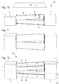
figure 10 représente, de façon schématisée et en perspective, un guidage à lames flexibles croisées en projection, entre une structure fixe et un élément inertiel ; - la
figure 11 représente, de façon similaire à lafigure 10 , un guidage flexible théorique dont chaque lame a un rapport d'aspect supérieur à celui des lames de lafigure 10 ; - la
figure 12 représente, de façon similaire à lafigure 10 , un guidage flexible, équivalent en termes de rappel élastique au guidage théorique de lafigure 11 , mais comportant un nombre supérieur de lames, dont chacune a un rapport d'aspect inférieur à 10, dans cette variante deux lames élémentaires d'un premier type sont superposées dans une première direction, et croisent en projection deux lames élémentaires d'un deuxième type qui sont aussi superposées entre elles et s'étendent dans une deuxième direction ; - la
figure 13 représente, de façon similaire à lafigure 12 , un autre guidage flexible, dont les quatre lames sont en quinconce ; - la
figure 14 représente, de façon similaire à lafigure 12 , encore un autre guidage flexible, dont les quatre lames comportent deux lames élémentaires d'un premier type dans une première direction, qui encadrent deux lames élémentaires d'un deuxième type qui sont superposées entre elles et s'étendent dans une deuxième direction ; - la
figure 15 représente, de façon similaire à lafigure 12 , un autre guidage flexible, comportant six lames superposées par trois ; - la
figure 16 représente, de façon similaire à lafigure 13 , un autre guidage flexible, dont les six lames sont en quinconce ; - la
figure 17 représente, de façon similaire à lafigure 14 , un autre guidage flexible, dont les huit lames comportent une première et une deuxième superposition de deux lames élémentaires d'un premier type dans une première direction, qui encadrent quatre lames élémentaires d'un deuxième type qui sont superposées entre elles et s'étendent dans une deuxième direction ; - la
figure 18 représente, de façon similaire à lafigure 12 , encore un autre guidage flexible, à nombre inégal de lames, dont les cinq lames comportent deux lames élémentaires d'un premier type dans une première direction, qui encadrent trois lames élémentaires d'un deuxième type qui sont superposées entre elles et s'étendent dans une deuxième direction ; - la
figure 19 est identique à lafigure 13 , et lafigure 20 montre la décomposition de ce guidage flexible à quatre lames alternées en deux sous-unités de pivots à deux lames ; - la
figure 21 est identique à lafigure 14 , et lafigure 22 montre la décomposition de ce guidage flexible à quatre lames encadrées en deux sous-unités de pivots à deux lames ; - la
figure 23 représente, de façon schématisée, et, ramenés dans le même plan, la partie supérieure et la partie inférieure d'un oscillateur avec un tel guidage flexible décomposé en plusieurs sous-unités, dans le cas d'espèce un étage supérieur et un étage inférieur, avec des tables de translation interposées entre le support fixe et l'appui des lames vers l'élément inertiel, ces tables de translation comportant des guidages élastiques souples selon les directions X et Y des bissectrices aux directions en projection des lames ; - la
figure 24 est similaire à lafigure 23 , et comporte un réglage de position en X sur une partie rigide inférieure, de façon à modifier l'écart entre les projections des croisements des lames supérieures et inférieures ; - les
figures 25 à 27 illustrent d'autres variantes de tables de translation ; - la
figure 28 représente, de façon schématisée, et en vue de côté, la partie supérieure et la partie inférieure d'un oscillateur avec un guidage flexible décomposé en deux sous-unités, dans le cas d'espèce un étage supérieur et un étage inférieur, avec une table de translation interposée entre le support fixe et l'appui supérieur des lames supérieures vers l'élément inertiel.
- the
figure 1 schematically represents, in perspective, a first variant of mechanical oscillator, which comprises a rigid support element, of elongated shape, for its attachment to a plate of the movement or the like, to which is suspended a massive inertial element by two first flexible disjoint, crossed in projection on the plane of oscillation of this inertial element, which cooperates with a classic escapement mechanism with Swiss anchor and standard escape wheel; - the
figure 2 represents, schematically, and in plan, the oscillator of thefigure 1 ; - the
figure 3 represents, schematically, and in section passing through the axis of crossing of the blades, the oscillator of thefigure 1 ; - the
figure 4 represents, in a schematic form, a detail of thefigure 2 , showing the offset between the crossing of the blades and the projection of the center of mass of the resonator, this offset detail being applicable in the same way to the various variants described below; - the
figure 5 is a graph, with abscissa X = D / L ratio between, on the one hand the distance D of the embedding point of a blade in the fixed mass and the point of intersection, and on the other hand the total length L the same blade between its two opposite recesses, and ordinate the angle at the crossing vertex of the flexible blades, and which defines two curves, lower and upper, in broken lines, which limit the appropriate range between these parameters to ensure the isochronism, the curve in solid line corresponding to an advantageous value; - the
figure 6 represents, similarly to thefigure 1 a second variant of a mechanical oscillator, in which the rigid support member, of elongate shape, is also movable relative to a fixed structure, and is carried by a third rigid element, via a second set of blades flexible, arranged similarly to the first flexible blades, the inertial element being further arranged to cooperate with a conventional exhaust mechanism not shown; - the
figure 7 represents, schematically, and in plan, the oscillator of thefigure 6 ; - the
figure 8 represents, schematically, and in section passing through the axis of crossing of the blades, the oscillator of thefigure 1 ; - the
figure 9 is a block diagram showing a watch that has movement with such a resonator; - the
figure 10 represents, schematically and in perspective, a guide with flexible blades crossed in projection, between a fixed structure and an inertial element; - the
figure 11 represents, similarly to thefigure 10 , a theoretical flexible guide whose each blade has an aspect ratio greater than that of the blades of thefigure 10 ; - the
figure 12 represents, similarly to thefigure 10 , a flexible guide, equivalent in terms of elastic return to the theoretical guidance of thefigure 11 , but having a greater number of blades, each of which has an aspect ratio of less than 10, in this variant two elementary blades of a first type are superimposed in a first direction, and intersect in projection two elementary blades of a second type which are also superimposed between them and extend in a second direction; - the
figure 13 represents, similarly to thefigure 12 another flexible guide whose four blades are staggered; - the
figure 14 represents, similarly to thefigure 12 , yet another flexible guide, the four blades comprise two elementary blades of a first type in a first direction, which frame two elementary blades of a second type which are superimposed between them and extend in a second direction; - the
figure 15 represents, similarly to thefigure 12 , another flexible guide, comprising six blades superimposed by three; - the
figure 16 represents, similarly to thefigure 13 another flexible guide whose six blades are staggered; - the
figure 17 represents, similarly to thefigure 14 another flexible guide, the eight blades of which comprise a first and a second superposition of two elementary blades of a first type in a first direction, which frame four elementary blades of a second type which are superimposed between them and extend in a second direction; - the
figure 18 represents, similarly to thefigure 12 , yet another flexible guide, with unequal number of blades, whose five blades comprise two elementary blades of a first type in a first direction, which frame three elementary blades of a second type which are superimposed between them and extend in a second direction; - the
figure 19 is identical to thefigure 13 , and thefigure 20 shows the decomposition of this flexible guide with four alternate blades into two sub-units of two-blade pivots; - the
figure 21 is identical to thefigure 14 , and thefigure 22 shows the decomposition of this flexible guide with four framed blades in two sub-units of pivots with two blades; - the
figure 23 represents, schematically, and, brought in the same plane, the upper part and the lower part of an oscillator with such a flexible guide decomposed into several subunits, in the case in point an upper stage and a lower stage , with translational tables interposed between the fixed support and the support of the blades to the inertial element, these translational tables having flexible elastic guides along the X and Y directions of the bisectors to the projection directions of the blades; - the
figure 24 is similar to thefigure 23 , and has an X-position adjustment on a lower rigid portion, so as to change the gap between the projections of the crossings of the upper and lower blades; - the
Figures 25 to 27 illustrate other variants of translation tables; - the
figure 28 schematically shows, in side view, the upper part and the lower part of an oscillator with a flexible guide decomposed into two subunits, in this case an upper stage and a lower stage, with a translation table interposed between the fixed support and the upper support of the upper blades towards the inertial element.
L'invention concerne un oscillateur mécanique 100 d'horlogerie, comportant au moins un élément support rigide 4 fixé directement ou indirectement sur une platine 900, et un élément inertiel massif 5. Cet oscillateur 100 comporte, entre l'élément support rigide 4 et l'élément inertiel massif 5, un mécanisme de guidage flexible 200. Ce mécanisme de guidage flexible comporte au moins deux premières lames flexibles 31, 32, qui supportent l'élément inertiel massif 5 et sont agencées pour le rappeler vers une position de repos. Cet élément inertiel massif 5 est agencé pour osciller angulairement selon un plan d'oscillation autour de cette position de repos.The invention relates to a
Les deux premières lames flexibles 31 et 32 ne se touchent pas, et, en position de repos, leurs projections sur le plan d'oscillation se croisent en un point de croisement P, au voisinage immédiat duquel ou par lequel passe l'axe de rotation de l'élément inertiel massif 5 perpendiculairement au plan d'oscillation. Tous les éléments géométriques décrits ci-après s'entendent, sauf mention contraire, comme étant considérés dans la position de repos de l'oscillateur à l'arrêt.The first two
Les
Les encastrements des premières lames flexibles 31, 32, avec l'élément support rigide 4 et l'élément inertiel massif 5 définissent au moins deux directions de lames DL1, DL2, qui sont parallèles au plan d'oscillation et qui font entre elles, en projection sur le plan d'oscillation, un angle au sommet α.The embedding of the first
La position du point de croisement P est définie par le rapport X= D/L où D est la distance entre la projection, sur le plan d'oscillation, de l'un des points d'encastrement des premières lames 31, 32, dans le premier élément de support rigide 4 et le point de croisement P, et où L est la longueur totale de la projection, sur le plan d'oscillation, de la lame 31, 32, concernée. Et la valeur du rapport D/L est comprise entre 0 et 1, et l'angle au sommet α est inférieur ou égal à 70°.The position of the crossing point P is defined by the ratio X = D / L where D is the distance between the projection, on the plane of oscillation, of one of the insertion points of the
De façon avantageuse, à la fois l'angle au sommet α est inférieur ou égal à 60°, et, pour chaque première lame flexible 31, 32, le rapport d'encastrement D1/L1, D2/L2, est compris entre 0.15 et 0.85, bornes comprises.Advantageously, both the angle at the apex α is less than or equal to 60 °, and, for each first
De façon particulière, tel que visible sur les
Plus particulièrement, et tel qu'illustré sur les figures, les premières lames 31, 32, et leurs encastrements définissent ensemble un pivot 1 qui, en projection sur le plan d'oscillation, est symétrique par rapport à un axe de symétrie AA passant par le point de croisement P.More particularly, and as shown in the figures, the
Plus particulièrement, quand le pivot 1 est symétrique par rapport à l'axe de symétrie AA, en position de repos, en projection sur le plan d'oscillation, le centre de masse de l'élément inertiel massif 5 est situé sur l'axe de symétrie AA du pivot 1. En projection, ce centre de masse peut être confondu ou non avec le point de croisement P.More particularly, when the
Plus particulièrement encore, le centre de masse de l'élément inertiel massif 5 est situé à une distance non nulle du point de croisement P correspondant à l'axe de rotation de l'élément inertiel massif 5, tel que visible sur les
De façon particulière, en projection sur le plan d'oscillation, le centre de masse de l'élément inertiel massif 5 est situé sur l'axe de symétrie AA du pivot 1, et est situé à distance non nulle du point de croisement P laquelle est comprise entre 0.1 fois et 0.2 fois la longueur totale L de la projection, sur le plan d'oscillation, de la lame 31, 32.In particular, in projection on the oscillation plane, the center of mass of the massive
Plus particulièrement, les premières lames 31 et 32 sont des lames droites.More particularly, the
Plus particulièrement encore, l'angle au sommet α est inférieur ou égal à 50°, ou encore est inférieur ou égal à 40°, ou encore inférieur ou égal à 35°, ou encore inférieur ou égal à 30°.More particularly, the apex angle α is less than or equal to 50 °, or is less than or equal to 40 °, or less than or equal to 35 °, or even less than or equal to 30 °.
Plus particulièrement, le rapport d'encastrement D1/L1, D2/L2, est compris entre 0.15 et 0.49, bornes comprises, ou entre 0.51 et 0.85, bornes comprises, tel que visible sur la
Dans une variante, et plus particulièrement selon l'exécution selon la
Dans une variante, et plus particulièrement selon l'exécution selon la
Dans une variante, et plus particulièrement selon l'exécution selon la
De façon avantageuse, et tel que visible sur la ![]()
![]()
![]()
![]()
![]()
![]()
![]()
![]()
![]()
![]()
![]()
![]()
![]()
![]()
Plus particulièrement, et notamment dans l'exécution non limitative illustrée par les figures, les premières lames flexibles 31 et 32 ont la même longueur L, et la même distance D.More particularly, and particularly in the non-limiting embodiment illustrated by the figures, the first
Plus particulièrement, entre leurs encastrements, ces premières lames flexibles 31 et 32 sont identiques.More particularly, between their recesses, these first
Les
Plus particulièrement, dans la réalisation non limitative illustrée par les figures, les projections des premières lames flexibles 31, 32, et des secondes lames flexibles 33, 34, sur le plan d'oscillation se croisent au même point de croisement P.More particularly, in the nonlimiting embodiment illustrated by the figures, the projections of the first
Dans une autre forme particulière d'exécution non illustrée, en position de repos, en projection sur le plan d'oscillation, les projections des premières lames flexibles 31, 32, et des secondes lames flexibles 33, 34, sur le plan d'oscillation se croisent en deux points distincts tous deux situés sur l'axe de symétrie AA du pivot 1, quand le pivot 1 est symétrique par rapport à l'axe de symétrie AA.In another particular embodiment not shown, in the rest position, in projection on the plane of oscillation, the projections of the first
Plus particulièrement, les encastrements des secondes lames flexibles 33, 34, avec l'élément support rigide 4 et le troisième élément rigide 6, définissent deux directions de lames parallèles au plan d'oscillation et faisant entre elles, en projection sur le plan d'oscillation, un angle au sommet de même bissectrice que l'angle au sommet α que les premières lames flexibles 31, 32. Plus particulièrement encore, ces deux directions des secondes lames flexibles 33, 34, présentent le même angle au sommet α que les premières lames flexibles 31, 32.More particularly, the embedding of the second
Plus particulièrement, les secondes lames flexibles 33, 34, sont identiques aux premières lames flexibles 31, 32, comme dans l'exemple non limitatif des figures.More particularly, the second
Plus particulièrement, quand le pivot 1 est symétrique par rapport à l'axe de symétrie AA, en position de repos, en projection sur le plan d'oscillation, le centre de masse de l'élément inertiel massif 5 est situé sur l'axe de symétrie AA du pivot 1.More particularly, when the
De façon similaire et particulière, quand le pivot 1 est symétrique par rapport à l'axe de symétrie AA, en position de repos, le centre de masse de l'élément support rigide 4 est situé, en projection sur le plan d'oscillation, sur l'axe de symétrie AA du pivot 1.In a similar and particular way, when the
Dans une variante particulière, quand le pivot 1 est symétrique par rapport à l'axe de symétrie AA, en position de repos, en projection sur le plan d'oscillation, à la fois le centre de masse du élément inertiel massif 5 et le centre de masse du élément support rigide 4 sont situés sur l'axe de symétrie AA du pivot 1. Plus particulièrement encore, les projections du centre de masse de l'élément inertiel massif 5 et du centre de masse de l'élément support rigide 4, sur l'axe de symétrie AA du pivot 1, sont confondues.In a particular variant, when the
Une configuration particulière illustrée par les figures pour de tels pivots superposés est celle où les projections des premières lames flexibles 31, 32, et des secondes lames flexibles 33, 34, sur le plan d'oscillation se croisent au même point de croisement P, qui correspond aussi à la projection du centre de masse de l'élément inertiel massif 5, ou du moins qui en est la plus proche possible. Plus particulièrement ce même point correspond aussi à la projection du centre de masse de l'élément support rigide 4. Plus particulièrement encore, ce même point correspond aussi à la projection du centre de masse de l'oscillateur 100 tout entier.A particular configuration illustrated by the figures for such superposed pivots is that where the projections of the first
Dans une variante particulière de cette configuration de pivots superposés, quand le pivot 1 est symétrique par rapport à l'axe de symétrie AA, en position de repos, en projection sur le plan d'oscillation, le centre de masse de l'élément inertiel massif 5 est situé sur l'axe de symétrie AA du pivot 1, et à une distance non nulle du point de croisement correspondant à l'axe de rotation de l'élément inertiel massif 5, laquelle distance non nulle est comprise entre 0.1 fois et 0.2 fois la longueur totale L de la projection, sur le plan d'oscillation, de la lame 33, 34, avec un écart similaire à l'écart ε des
De façon similaire et particulière, quand le pivot 1 est symétrique par rapport à l'axe de symétrie AA, le centre de masse de l'élément inertiel massif 5 est situé, en projection sur le plan d'oscillation, sur l'axe de symétrie AA du pivot 1 et à une distance non nulle du point de croisement correspondant à l'axe de rotation de l'élément support rigide 4 laquelle distance non nulle est comprise entre 0.1 fois et 0.2 fois la longueur totale L de la projection, sur le plan d'oscillation, de la lame 31, 32.In a similar and particular way, when the
De façon similaire et particulière, quand le pivot 1 est symétrique par rapport à l'axe de symétrie AA, le centre de masse de l'élément support rigide 4 est situé, en projection sur le plan d'oscillation, sur l'axe de symétrie AA du pivot 1 et à une distance non nulle du point de croisement P correspondant à l'axe de rotation de l'élément inertiel massif 5. Notamment cette distance non nulle est comprise entre 0.1 fois et 0.2 fois la longueur totale L de la projection, sur le plan d'oscillation, de la lame 33, 34.In a similar and particular way, when the
De façon similaire et particulière, quand le pivot 1 est symétrique par rapport à l'axe de symétrie AA, le centre de masse de l'élément support rigide 4 est situé, en projection sur le plan d'oscillation, sur l'axe de symétrie AA du pivot 1 et à une distance non nulle du point de croisement correspondant à l'axe de rotation de l'élément support rigide 4 laquelle distance non nulle est comprise entre 0.1 fois et 0.2 fois la longueur totale L de la projection, sur le plan d'oscillation, de la lame 31, 32.In a similar and particular way, when the
De façon similaire et particulière, le centre de masse de l'élément support rigide 4 est situé sur l'axe de symétrie AA du pivot 1 et à la distance non nulle du point de croisement P laquelle est comprise entre 0.1 fois et 0.2 fois la longueur totale L de la projection, sur le plan d'oscillation, de la lame 33, 34.Similarly and particularly, the center of mass of the
Plus particulièrement, et tel que visible sur la variante des figures, quand le pivot 1 est symétrique par rapport à l'axe de symétrie AA, en projection sur le plan d'oscillation, le centre de masse de l'oscillateur 100 dans sa position de repos est situé sur l'axe de symétrie AA.More particularly, and as visible in the variant of the figures, when the
Plus particulièrement, l'élément inertiel massif 5 est allongé selon la direction de l'axe de symétrie AA du pivot 1, quand le pivot 1 est symétrique par rapport à l'axe de symétrie AA. C'est par exemple le cas des
L'invention se prête bien à une exécution monolithique des lames et des composants massifs qu'elles joignent, en matériau micro-usinable ou au moins partiellement amorphe, avec une mise en oeuvre par procédé « MEMS » ou « LIGA » ou similaire. En particulier, dans le cas d'une exécution en silicium, l'oscillateur 100 est avantageusement compensé thermiquement par ajout de dioxyde de silicium sur des lames flexibles en silicium. Dans une variante, les lames peuvent être assemblées, par exemple encastrées dans des rainures, ou autre.The invention lends itself well to a monolithic execution of the blades and the solid components they join, made of micro-machinable material or at least partially amorphous, with an implementation by "MEMS" or "LIGA" method or the like. In particular, in the case of a silicon embodiment, the
Lorsque on a deux pivots en série, comme dans le cas de
Les variantes illustrées comportent tous les axes de pivotement, croisements de lames, et centres de masse, coplanaires, ce qui est un cas particulier avantageux, mais non limitatif.The illustrated variants comprise all pivot axes, blade crossings, and mass centers, coplanar, which is a special case that is advantageous, but not limiting.
On comprend qu'il est ainsi possible d'obtenir une course angulaire qui est grande: en tous les cas supérieure à 30°, elle peut même atteindre 50° voire 60°, ce qui la rend compatible en combinaison avec tous les échappements mécaniques usuels, ancre suisse, détente, co-axial, ou autre.It is understood that it is thus possible to obtain an angular stroke which is large: in all cases greater than 30 °, it can even reach 50 ° or even 60 °, which makes it compatible in combination with all the usual mechanical exhausts , Swiss anchor, relaxation, co-axial, or other.
Il s'agit, encore, de déterminer une solution pratique qui soit équivalente à l'utilisation théorique d'une grande valeur du rapport d'aspect des lames.It is still necessary to determine a practical solution that is equivalent to the theoretical use of a large value of the aspect ratio of the blades.
A cet effet, il est avantageux de subdivises les lames dans le sens de la longueur, en substituant à une lame unique une pluralité de lames élémentaires dont le comportement global soit équivalent, et où chacune des lames élémentaires a un rapport d'aspect limité à une valeur seuil. On diminue ainsi, par rapport à une lame unique de référence, le rapport d'aspect de chaque lame élémentaire, pour retrouver l'optimum d'isochronisme et d'insensibilité aux positions.For this purpose, it is advantageous to subdivide the blades lengthwise, substituting for a single blade a plurality of elementary blades whose overall behavior is equivalent, and where each of the elementary blades has an aspect ratio limited to a threshold value. Thus, compared to a single reference plate, the aspect ratio of each elementary plate is reduced to find the optimum of isochronism and insensitivity to the positions.
Chaque lame 31, 32, a un rapport d'aspect RA = H/E, où H est la hauteur de la lame 31,32, perpendiculairement à la fois au plan d'oscillation et à l'élongation de la lame 31, 32, selon la longueur L, et où E est l'épaisseur de la lame 31, 32, dans le plan d'oscillation et perpendiculairement à l'élongation de la lame 31, 32, selon la longueur L.Each
De façon préférée, le rapport d'aspect RA = H/E est inférieur à 10 pour chaque lame 31, 32. Plus particulièrement ce rapport d'aspect est inférieur à 8. Et le nombre total des lames flexibles 31, 32, est strictement supérieur à deux.Preferably, the aspect ratio RA = H / E is less than 10 for each
Plus particulièrement, l'oscillateur 100 comporte un premier nombre N1 de premières lames appelées lames primaires 31 s'étendant selon une première direction de lame DL1, et un deuxième nombre N2 de premières lames secondaires 32 s'étendant selon une deuxième direction de lame DL2, le premier nombre N1 et le deuxième nombre N2 étant chacun supérieur ou égal à deux.More particularly, the
Plus particulièrement, le premier nombre N1 est égal au deuxième nombre N2.More particularly, the first number N1 is equal to the second number N2.
Plus particulièrement encore, l'oscillateur 100 comporte au moins une paire formée d'une lame primaire 31 s'étendant selon une première direction de lame DL1, et d'une lame secondaire 32 s'étendant selon une deuxième direction de lame DL2. Et, dans chaque paire, la lame primaire 31 est identique à la lame secondaire 32 à l'orientation près.More particularly, the
Dans une variante particulière, l'oscillateur 100 ne comporte que des paires chacune formée d'une lame primaire 31 s'étendant selon une première direction de lame DL1, et d'une lame secondaire 32 s'étendant selon une deuxième direction de lame DL2, et, dans chaque paire, la lame primaire 31 est identique à la lame secondaire 32 à l'orientation près.In a particular variant, the
Dans une autre variante, l'oscillateur100 comporte au moins un groupe de lames formé d'une lame primaire 31 s'étendant selon une première direction de lame DL1, et d'une pluralité de lames secondaires 32 s'étendant selon une deuxième direction de lame DL2. Et, dans ce cas, dans chaque groupe de lames, le comportement élastique de la lame primaire 31 est identique au comportement élastique résultant du cumul de la pluralité de lames secondaires 32 à l'orientation près.In another variant, the
On remarque encore que, si le comportement d'une lame flexible dépend de son rapport d'aspect RA, il dépend également de la valeur de la courbure qui lui est imprimée. Sa déformée dépend à la fois de la valeur du rapport d'aspect et de la valeur locale du rayon de courbure, notamment à l'encastrement. C'est la raison pour laquelle on adopte, de préférence, une disposition des lames en symétrie en projection plane.Note also that, if the behavior of a flexible blade depends on its RA aspect ratio, it also depends on the value of the curvature that is printed on it. Its deformity depends both on the value of the aspect ratio and the local value of the radius of curvature, especially on embedding. This is the reason why one adopts, preferably, a disposition of the blades in plane projection symmetry.
L'invention concerne encore un mouvement d'horlogerie 1000 comportant au moins un tel oscillateur 100 mécanique.The invention also relates to a
L'invention concerne encore une montre 2000 comportant au moins un tel mouvement d'horlogerie 1000.The invention also relates to a
Un procédé de fabrication convenable consiste à effectuer, pour les différents types de pivots ci-dessous, les opérations suivantes :
Pour un type de pivot AABB :
- a. utiliser un substrat avec au moins quatre couches, résultant par exemple mais non limitativement de l'assemblage de deux wafers SOI ;
- b. graver par procédé de gravure "DRIE" face avant pour obtenir AA, avec notamment gravure des deux couches d'un seul tenant ;
- c. graver par procédé de gravure "DRIE" face arrière pour obtenir BB, avec notamment gravure des deux couches d'un seul tenant ;
- d. effectuer la séparation partielle des quatre couches par gravure de l'oxyde enterré.
For a pivot type AABB:
- at. using a substrate with at least four layers, resulting for example but not limited to the assembly of two SOI wafers;
- b. engraving by "DRIE" engraving process front face to obtain AA, with particular engraving of the two layers in one piece;
- c. engraving by a "DRIE" engraving process on the back side to obtain BB, in particular engraving of the two layers in one piece;
- d. perform the partial separation of the four layers by etching the buried oxide.
La grande précision du procédé "DRIE", c'est-à-dire gravure ionique réactive profonde (en anglais Deep Reactive Ion Etching DRIE) garantit une très bonne précision en positionnement et en alignement, inférieure ou égale à 5 micromètres, grâce à un alignement optique, ce qui garantit un très bon alignement face à face. Naturellement des procédés équivalents peuvent être mis en oeuvre selon le matériau choisi.The high precision of the "DRIE" process, that is to say deep reactive ion etching (in English Deep Reactive Ion Etching DRIE) guarantees a very good accuracy in positioning and alignment, less than or equal to 5 micrometers, thanks to a optical alignment, which guarantees a very good face-to-face alignment. Of course, equivalent processes can be implemented depending on the chosen material.
Il est possible de mettre en oeuvre des substrats avec un nombre supérieur de couches, notamment un substrat à six couches disponibles, par exemple par assemblage de deux DSOI, pour obtenir une structure de type AAABBB.It is possible to implement substrates with a greater number of layers, in particular a substrate with six available layers, for example by assembling two DSOIs, to obtain a structure of the AAABBB type.
Une variante pour l'obtention d'un même type de pivot AABB consiste à :
- a. utiliser deux substrats SOI standard à deux couches ;
- b. graver par procédé de gravure "DRIE" le premier substrat, sur la face avant pour obtenir A, sur la face arrière pour obtenir A ;
- c. graver par procédé de gravure "DRIE" le deuxième substrat, sur la face avant pour obtenir B, sur la face arrière pour obtenir B ; en alternative des opérations b et c on peut, sur le premier substrat et sur le deuxième substrat effectuer la gravure outre des deux couches en une fois, sans effectuer une gravure face avant et face arrière ;
- d. effectuer l'assemblage « wafer à wafer » des deux substrats ou « pièce à pièce » des composants individuels, pour obtenir AABB. Le bon alignement des géométries est alors lié à la spécification de la machine de bonding « wafer à wafer » ou au process « pièce à pièce », de façon bien connue de l'homme du métier.
- at. use two standard two-layer SOI substrates;
- b. engraving by the "DRIE" engraving method the first substrate, on the front face to obtain A, on the rear face to obtain A;
- c. engraving by the "DRIE" engraving method the second substrate, on the front face to obtain B, on the rear face to obtain B; as an alternative to operations b and c, it is possible, on the first substrate and on the second substrate, to etch off the two layers at once, without performing etching front and back;
- d. perform the "wafer wafer" assembly of the two substrates or "piece by piece" of the individual components, to obtain AABB. The proper alignment of the geometries is then linked to the specification of the "wafer to wafer" bonding machine or the "piece-to-piece" process, as is well known to those skilled in the art.
Pour un type de pivot ABAB :
- a. utiliser deux substrats SOI standard à deux couches ;
- b. graver par procédé de gravure "DRIE" le premier substrat, sur la face avant pour obtenir A, sur la face arrière pour obtenir B ;
- c. graver par procédé de gravure "DRIE" le deuxième substrat, sur la face avant pour obtenir A, sur la face arrière pour obtenir B ;
- d. effectuer l'assemblage « wafer à wafer » des deux substrats ou « pièce à pièce » des composants individuels, pour obtenir ABAB. Comme précédemment, Le bon alignement des géométries est lié à la spécification de la machine de bonding « wafer à wafer » ou au process « pièce à pièce ».
- at. use two standard two-layer SOI substrates;
- b. engraving by the "DRIE" engraving method the first substrate, on the front face to obtain A, on the rear face to obtain B;
- c. engraving by the "DRIE" engraving method the second substrate, on the front face to obtain A, on the rear face to obtain B;
- d. perform the "wafer wafer" assembly of the two substrates or "piece-by-piece" of the individual components, to obtain ABAB. As before, the correct alignment of the geometries is related to the specification of the "wafer to wafer" bonding machine or the "piece-to-piece" process.
Bien d'autres variantes de procédé peuvent être mises en oeuvre, selon le nombre de lames et l'équipement disponible.Many other process variants can be implemented, depending on the number of blades and the equipment available.
Les méthodes standard de fabrication par gravure DRIE du silicium ne permettent pas encore de fabriquer facilement un pivot monolithique ayant plus de deux niveaux distincts. Il est donc plus facile fabriquer des pièces séparées qui sont ensuite assemblées. Toutefois, la sensibilité aux erreurs d'assemblage nécessite une précision supérieure au micromètre, pour obtenir les propriétés optimales d'isochronisme et/ou d'insensibilité aux positions. Afin de résoudre ce problème, il est nécessaire d'adopter une stratégie de fabrication qui est décrite ci-dessous.Standard methods of manufacturing by DRIE etching of silicon do not yet make it easy to manufacture a monolithic pivot having more than two distinct levels. It is therefore easier to manufacture separate parts which are then assembled. However, the sensitivity to assembly errors requires a precision greater than one micrometer, to obtain the optimal properties of isochronism and / or insensitivity to the positions. In order to solve this problem, it is necessary to adopt a manufacturing strategy which is described below.
Dans une première démarche, il s'agit d'assembler avec une grande précision deux lames ayant des directions différentes. L'invention se propose de diviser le guidage flexible, ou pivot, en sous-unités composées de pivots à deux lames, par exemple une sous-unité supérieure et une sous-unité inférieure, dans le cas d'un guidage flexible comportant quatre lames, tel que visible sur la
La sous-unité supérieure est ensuite assemblée à la sous-unité inférieure.The upper subunit is then assembled to the lower subunit.
Cet assemblage peut être effectué par toute méthode traditionnelle: goupillage d'alignement et vissage, ou collage, ou « wafer fusion bonding », ou soudure, ou brasure, ou toute autre méthode connue de l'homme du métier.This assembly can be performed by any conventional method: alignment pinning and screwing, or bonding, or "wafer fusion bonding", or solder, or solder, or any other method known to those skilled in the art.
Le défaut d'assemblage se manifeste par un petit décalage Δ des axes de rotation des sous-unités supérieure et inférieure. De sorte que le mouvement de rotation du résonateur dicté par la sous-unité supérieure n'est pas en accord avec le mouvement de rotation dicté par la sous-unité inférieure. Pour éviter que ce décalage ne produise une sur-contrainte, le mécanisme comporte au moins une table de translation, dont le mouvement libre permet d'absorber le désaccord entre les deux rotations d'axes distincts. Au moins une des tables de translation doit être suffisamment souple pour que le désaccord de mouvement ne dégrade pas l'isochronisme. Dans le cas où l'on introduit deux tables de translation identiques, comme représenté dans la
Plus particulièrement, tel que visible sur les figures, le mécanisme de guidage flexible 200 comporte, superposés l'un sur l'autre, au moins un étage supérieur 28 et au moins un étage inférieur 29.More particularly, as can be seen in the figures, the flexible guiding mechanism 200 comprises, superimposed on one another, at least one
La sous-unité supérieure comporte un étage supérieur 28, qui comporte, entre un support supérieur 48 et un élément inertiel supérieur 58, au moins une lame primaire supérieure 318 s'étendant selon une première direction de lame supérieure DL1S et une lame secondaire supérieure 328 s'étendant selon une deuxième direction de lame supérieure DL2S, croisées en projection en un point de croisement supérieur PS.The upper subunit comprises an
La sous-unité inférieure comporte un étage inférieur 29, qui comporte, entre un support inférieur 49 et un élément inertiel inférieur 59, au moins une lame primaire inférieure 319 s'étendant selon une première direction de lame inférieure DL1I et une lame secondaire inférieure 329 s'étendant selon une deuxième direction de lame inférieure DL2I croisées en projection en un point de croisement inférieur PI, distant au repos du point de croisement supérieur PS d'un écart Δ.The lower subunit comprises a
Et au moins l'étage supérieur 28 ou l'étage inférieur 29 comporte, entre la platine 900 et le support supérieur 48, ou respectivement le support inférieur 49, une table de translation supérieure 308, ou respectivement une table de translation inférieure 309, qui comporte au moins une liaison élastique qui autorise la translation selon un ou deux axes de liberté dans le plan d'oscillation, et dont la raideur en translation selon ces deux axes est inférieure à celle de chaque lame flexible 31, 32, 333, 34, 318, 319, 328, 329, que comporte le mécanisme de guidage flexible 200.And at least the
Notons que cette liaison élastique n'autorise pas les rotations d'axe parallèle à celui du résonateur.Note that this elastic connection does not allow rotations of axis parallel to that of the resonator.
On notera qu'il n'est pas nécessaire que les directions supérieures DL1S et DL2S de l'étage supérieur 28 soient identiques aux directions inférieures DL1I et DL2I de l'étage inférieur 29. De préférence, elles possèdent les mêmes bissectrices.Note that it is not necessary that the upper directions DL1S and DL2S of the
Plus particulièrement, le point P par lequel passe l'axe de rotation de l'élément inertiel 5 est situé entre le point de croisement supérieur PS et le point de croisement inférieur PI, exactement au milieu si le mécanisme de guidage flexible 200 comporte deux tables de translations supérieure 308 et inférieure 309 qui sont identiques. Dans une variante, ce point P est situé exactement sur le point de croisement inférieur PI si l'étage inférieur 29 ne possède pas de table de translation, ou sur le point de croisement supérieur PS si l'étage supérieur 28 ne possède pas de table de translation.More particularly, the point P through which the axis of rotation of the
De préférence, l'oscillateur 100 comporte, pour chaque mécanisme de guidage flexible 200 qu'il comporte, un élément inertiel massif 5 est unique. Plus particulièrement, le mécanisme de guidage flexible 200 est unique, et l'élément inertiel massif 5 est unique.Preferably, the
Naturellement, la configuration préférée des tables de translation 308 et 309 illustrée par les figures n'est pas limitative. Ces tables de translation 308 et 309 peuvent aussi se trouver entre l'élément inertiel 5 et les encastrements du côté élément inertiel.Naturally, the preferred configuration of the translation tables 308 and 309 illustrated by the figures is not limiting. These translation tables 308 and 309 can also be between the
Si l'on définit par X et Y les axes des bissectrices des angles que font entre elles les projections des lames flexibles sur un plan parallèle commun, la combinaison des tables en translation, selon l'axe X et selon l'axe Y, doit être plus souple que le pivot flexible selon les mêmes axes. Cette règle est valable quel que soit le nombre d'étages, le cumul dû à la combinaison de toutes les tables, en translation, selon l'axe X et selon l'axe Y, doit être plus souple que le pivot flexible. La liaison élastique de la table de translation supérieure 308, ou respectivement de la table de translation inférieure 309, selon un ou deux axes de liberté dans le plan d'oscillation, est ainsi de préférence une liaison élastique selon ces axes X et Y.If we define by X and Y the axes of the bisectors of the angles between the projections of the flexible blades on a common parallel plane, the combination of the tables in translation, along the X axis and along the Y axis, must be more flexible than the flexible pivot according to the same axes. This rule is valid regardless of the number of stages, the cumulation due to the combination of all the tables, in translation, along the X axis and along the Y axis, must be more flexible than the flexible pivot. The elastic connection of the upper translation table 308, or respectively of the lower translation table 309, along one or two axes of freedom in the oscillation plane, is thus preferably an elastic connection along these axes X and Y.
Le stockage supplémentaire d'énergie élastique dans la ou les tables de translation, qui résulte du désaccord de mouvement, s'ajoute au stockage principal d'énergie du pivot, et tend à perturber l'isochronisme, sauf si la valeur du stockage supplémentaire est très inférieure à celle du stockage principal. C'est pourquoi les liaisons élastiques dans les tables de translation doivent être beaucoup plus souples que celles du pivot flexible.The additional storage of elastic energy in the translation table (s), which results from the movement mismatch, adds to the main energy storage of the pivot, and tends to disturb the isochronism, unless the value of the additional storage is much lower than the main storage. This is why the elastic connections in the translation tables must be much more flexible than those of the flexible pivot.
Plus particulièrement, l'étage supérieur 28 et l'étage inférieur 29 comportent chacun, entre la platine 900 et le support supérieur 48, et respectivement le support inférieur 49, une table de translation supérieure 308, ou respectivement une table de translation inférieure 309, comportant au moins une liaison élastique selon un ou deux axes de liberté dans le plan d'oscillation, et dont la raideur est inférieure à celle de chaque lame flexible.More particularly, the
Quand il existe une table de translation par étage, elles ne sont pas nécessairement identiques entre elles.When there is a translation table per floor, they are not necessarily identical to each other.
Une variante consiste à utiliser deux tables de translation différentes, la première étant souple afin que le désaccord de mouvement ne dégrade pas l'isochronisme, et la seconde étant rigide afin d'assurer le positionnement du pivot.An alternative is to use two different translation tables, the first being flexible so that the movement mismatch does not degrade the isochronism, and the second is rigid to ensure the positioning of the pivot.
Dans une autre variante, un étage peut comporter une table de translation, et l'autre étage avoir une fixation rigideIn another variant, one stage may comprise a translation table, and the other stage may have a rigid attachment
L'élément inertiel supérieur 58 et l'élément inertiel inférieur 59 constituent tout ou partie de l'élément inertiel massif 5, et sont rigidement liés, directement ou indirectement, entre eux. Le support supérieur 48 et le support inférieur 49 sont quant à eux, liés, selon le cas directement ou au travers d'une table de translation supérieure 308, ou respectivement une table de translation inférieure 309, à une partie rigide supérieure 480, respectivement une partie rigide inférieure 490, qui elles sont rigidement liées à l'élément support rigide 4, ou à la platine 900.The upper
Les
Ainsi, le mouvement de la table de translation, ou avantageusement des tables de translation, permet d'absorber le désaccord éventuel entre les rotations de la sous-unité supérieure et de la sous-unité inférieure. De plus, Chaque table de translation participe à la protection du mécanisme contre les fortes accélérations, lors d'une chute ou percussion par exemple.Thus, the movement of the translation table, or preferably translation tables, can absorb the possible disagreement between the rotations of the upper subunit and the lower subunit. In addition, each translation table contributes to the protection of the mechanism against strong accelerations, during a fall or percussion for example.
On comprend que l'assemblage tel que décrit ci-dessus dans le cadre de la première démarche permet de rendre négligeable l'anisochronisme ajouté, à condition que le défaut d'assemblage Δ soit suffisamment petit.It will be understood that the assembly as described above in the context of the first step makes it possible to make the added anisochronism negligible, provided that the assembly defect Δ is sufficiently small.
A contrario, on peut décider d'exagérer volontairement le défaut d'assemblage Δ, afin d'introduire de l'anisochronisme de façon contrôlée, par exemple pour compenser un retard à l'échappement. Il est alors avantageux de rendre mobile, et réglable, au moins l'un des encastrements à la platine, c'est-à-dire le support supérieur 48 et/ou le support inférieur 49 dans le cas de la variante particulière non limitative illustrée. En effet, en ajustant la position relative de ces deux encastrements, on modifie la rigidité des tables de translation 308, 309, ce qui a pour effet de permettre le réglage de l'anisochronisme ajouté. Un tel réglage peut être effectué facilement avec la combinaison d'une gorge et d'un excentrique, ou par toute autre solution connue de l'horloger.Conversely, it may be decided to deliberately exaggerate the assembly fault Δ, in order to introduce anisochronism in a controlled manner, for example to compensate for an exhaust delay. It is then advantageous to make mobile, and adjustable, at least one of the recesses to the plate, that is to say the
En somme, en déplaçant la position d'au moins un des encastrements à la platine, tel que visible sur la
Cet agencement particulier avec au moins une table de translation permet, en somme, de garantir l'alignement entre les étages supérieur et inférieur, et d'éviter les grandes contraintes que subiraient les lames si les étages supérieur et inférieur ne suivaient pas la même trajectoire.This particular arrangement with at least one translation table makes it possible, in short, to guarantee the alignment between the upper and lower stages, and to avoid the large stresses that the blades would suffer if the upper and lower stages did not follow the same trajectory. .
Une autre alternative encore consiste à équiper le mécanisme avec une table de translation supérieure 308 et d'une table de translation inférieure 309, avec un support supérieur 48 et un support inférieur 49 qui ne sont plus rigidement liés à l'élément support rigide 4, ou à la platine 900, mais qui sont contraints à des mouvements plans, inverses en X et en Y, par une liaison de type vilebrequin ou similaire, par rapport à un axe fixe de l'élément support rigide 4, ou de la platine 900. Cette solution a l'avantage de permettre d'ajuster l'anisochronisme sans pour autant déplacer légèrement l'axe de rotation du résonateur.Yet another alternative is to equip the mechanism with an upper translation table 308 and a lower translation table 309, with an
On comprend que les tables de translation, qui constituent des guidages flexibles en translation, peuvent être réalisées de bien des manières différentes. L'homme du métier en trouvera des exemples dans les références suivantes : [1]
La
Claims (19)
pour
for
Priority Applications (7)
| Application Number | Priority Date | Filing Date | Title |
|---|---|---|---|
| EP18185138.7A EP3438762A3 (en) | 2017-07-28 | 2018-07-24 | Timepiece oscillator having flexible guides with wide angular travel |
| EP18205260.5A EP3561607B1 (en) | 2018-04-23 | 2018-11-08 | Collision protection of a resonator mechanism with rotatable flexible guiding |
| JP2019124349A JP6843191B2 (en) | 2018-07-24 | 2019-07-03 | Timekeeping oscillator with flexor bearings with long square strokes |
| US16/511,191 US10935933B2 (en) | 2018-07-24 | 2019-07-15 | Timepiece oscillator with flexure bearings having a long angular stroke |
| CN201910670433.0A CN110780572B (en) | 2018-07-24 | 2019-07-24 | Mechanical timepiece oscillator, and timepiece movement and watch including the same |
| JP2019195910A JP6828117B2 (en) | 2018-04-23 | 2019-10-29 | Impact protection for resonant mechanisms with rotary deflection supports |
| CN201911081303.XA CN111158230B (en) | 2018-04-23 | 2019-11-07 | Anti-seismic protection for resonator mechanism with rotating compliant bearing |
Applications Claiming Priority (3)
| Application Number | Priority Date | Filing Date | Title |
|---|---|---|---|
| EP17183666.1A EP3435170B1 (en) | 2017-07-28 | 2017-07-28 | Timepiece oscillator having flexible guides with wide angular travel |
| EP18179623.6A EP3451073B1 (en) | 2017-07-28 | 2018-06-25 | Timepiece oscillator having flexible guides with wide angular travel |
| EP18185138.7A EP3438762A3 (en) | 2017-07-28 | 2018-07-24 | Timepiece oscillator having flexible guides with wide angular travel |
Publications (2)
| Publication Number | Publication Date |
|---|---|
| EP3438762A2 true EP3438762A2 (en) | 2019-02-06 |
| EP3438762A3 EP3438762A3 (en) | 2019-03-13 |
Family
ID=68137772
Family Applications (1)
| Application Number | Title | Priority Date | Filing Date |
|---|---|---|---|
| EP18185138.7A Pending EP3438762A3 (en) | 2017-07-28 | 2018-07-24 | Timepiece oscillator having flexible guides with wide angular travel |
Country Status (1)
| Country | Link |
|---|---|
| EP (1) | EP3438762A3 (en) |
Cited By (3)
| Publication number | Priority date | Publication date | Assignee | Title |
|---|---|---|---|---|
| CN112711183A (en) * | 2019-10-24 | 2021-04-27 | 斯沃奇集团研究和开发有限公司 | Pivot guide device for a pivoting mass and timepiece resonator mechanism |
| EP3992728A1 (en) * | 2020-10-29 | 2022-05-04 | The Swatch Group Research and Development Ltd | Flexible guide with translation table for rotary resonator mechanism, in particular for a timepiece movement |
| EP4191346A1 (en) * | 2021-12-06 | 2023-06-07 | The Swatch Group Research and Development Ltd | Shock protection of a resonator mechanism with rotatable flexible guiding |
Citations (5)
| Publication number | Priority date | Publication date | Assignee | Title |
|---|---|---|---|---|
| US3628781A (en) | 1969-10-03 | 1971-12-21 | Philamon Inc | Compound tine for tuning fork or the like |
| EP1419039A1 (en) | 2000-10-03 | 2004-05-19 | Dan Appels Engineering BV | Method and apparatus for the recycling of bituminous materials, more in particular bituminous roofcovering materials |
| CH709536A2 (en) | 2014-02-17 | 2015-10-15 | Eta Sa Manufacture Horlogère Suisse | Clockwork mechanism regulator with two oscillators. |
| EP3035127A1 (en) | 2014-12-18 | 2016-06-22 | The Swatch Group Research and Development Ltd. | Clock oscillator with tuning fork |
| EP3130966A1 (en) | 2015-08-11 | 2017-02-15 | ETA SA Manufacture Horlogère Suisse | Mechanical clockwork provided with a motion feedback system |
Family Cites Families (3)
| Publication number | Priority date | Publication date | Assignee | Title |
|---|---|---|---|---|
| EP2998800B1 (en) * | 2014-09-16 | 2019-01-16 | Patek Philippe SA Genève | Timepiece component with flexible pivot |
| CH713165B1 (en) * | 2016-11-16 | 2021-10-29 | Swatch Group Res & Dev Ltd | Protection of the blades of a mechanical watch resonator in the event of an impact. |
| EP3327515B1 (en) * | 2016-11-23 | 2020-05-06 | ETA SA Manufacture Horlogère Suisse | Flexibly guided rotary resonator maintained by a free escapement with pallet |
-
2018
- 2018-07-24 EP EP18185138.7A patent/EP3438762A3/en active Pending
Patent Citations (5)
| Publication number | Priority date | Publication date | Assignee | Title |
|---|---|---|---|---|
| US3628781A (en) | 1969-10-03 | 1971-12-21 | Philamon Inc | Compound tine for tuning fork or the like |
| EP1419039A1 (en) | 2000-10-03 | 2004-05-19 | Dan Appels Engineering BV | Method and apparatus for the recycling of bituminous materials, more in particular bituminous roofcovering materials |
| CH709536A2 (en) | 2014-02-17 | 2015-10-15 | Eta Sa Manufacture Horlogère Suisse | Clockwork mechanism regulator with two oscillators. |
| EP3035127A1 (en) | 2014-12-18 | 2016-06-22 | The Swatch Group Research and Development Ltd. | Clock oscillator with tuning fork |
| EP3130966A1 (en) | 2015-08-11 | 2017-02-15 | ETA SA Manufacture Horlogère Suisse | Mechanical clockwork provided with a motion feedback system |
Non-Patent Citations (1)
| Title |
|---|
| LARRY L. HOWELL: "Handbook of compilant mechanisms", WILEY |
Cited By (8)
| Publication number | Priority date | Publication date | Assignee | Title |
|---|---|---|---|---|
| CN112711183A (en) * | 2019-10-24 | 2021-04-27 | 斯沃奇集团研究和开发有限公司 | Pivot guide device for a pivoting mass and timepiece resonator mechanism |
| EP3812842A1 (en) * | 2019-10-24 | 2021-04-28 | The Swatch Group Research and Development Ltd | Device for guiding the pivoting of a pivoting mass and timepiece resonator mechanism |
| JP2021067685A (en) * | 2019-10-24 | 2021-04-30 | ザ・スウォッチ・グループ・リサーチ・アンド・ディベロップメント・リミテッド | Pivoting guide device for pivoting mass and time measuring instrument resonator mechanism |
| JP7021326B2 (en) | 2019-10-24 | 2022-02-16 | ザ・スウォッチ・グループ・リサーチ・アンド・ディベロップメント・リミテッド | Pivot guidance device and timekeeper resonator mechanism for pivot mass |
| CN112711183B (en) * | 2019-10-24 | 2022-04-12 | 斯沃奇集团研究和开发有限公司 | Pivot guide device for a pivoting mass and timepiece resonator mechanism |
| US11789407B2 (en) | 2019-10-24 | 2023-10-17 | The Swatch Group Research And Development Ltd | Pivoting guide device for a pivoting mass and timepiece resonator mechanism |
| EP3992728A1 (en) * | 2020-10-29 | 2022-05-04 | The Swatch Group Research and Development Ltd | Flexible guide with translation table for rotary resonator mechanism, in particular for a timepiece movement |
| EP4191346A1 (en) * | 2021-12-06 | 2023-06-07 | The Swatch Group Research and Development Ltd | Shock protection of a resonator mechanism with rotatable flexible guiding |
Also Published As
| Publication number | Publication date |
|---|---|
| EP3438762A3 (en) | 2019-03-13 |
Similar Documents
| Publication | Publication Date | Title |
|---|---|---|
| EP3254158B1 (en) | Isochronous clock resonator | |
| EP3054358B1 (en) | Clock oscillator mechanism | |
| EP3438762A2 (en) | Timepiece oscillator having flexible guides with wide angular travel | |
| EP2917788A2 (en) | Method for the production of a multistable flexible element | |
| WO2011120180A1 (en) | Immobilizing device for a toothed wheel | |
| WO2012010408A1 (en) | Oscillating mechanism with elastic pivot and mobile for the transmission of energy | |
| EP3054356B1 (en) | Isochronous clock resonator | |
| EP3561607B1 (en) | Collision protection of a resonator mechanism with rotatable flexible guiding | |
| EP3435172B1 (en) | Method for producing a flexible guide mechanism for a timepiece mechanical oscillator | |
| CH714031A2 (en) | Clock oscillator with flexible guides with long angular travel. | |
| CH715526A2 (en) | Shock protection of a resonator mechanism with flexible rotary guide. | |
| WO2017032528A1 (en) | Bistable mechanical device, notably for horology | |
| EP3037893B1 (en) | Micromechanical or clock component with flexible guidance | |
| EP3451073B1 (en) | Timepiece oscillator having flexible guides with wide angular travel | |
| EP3435171B1 (en) | Timepiece oscillator having flexible guides with wide angular travel | |
| EP3637196B1 (en) | Mechanical oscillator | |
| EP3707564B1 (en) | Horological assembly comprising a horological component and a device for guiding the translation of a mobile component | |
| CH719206A2 (en) | Clockwork resonator mechanism with rotating flexible guide. | |
| CH713837B1 (en) | Regulation device based on an isotropic harmonic oscillator for a timepiece. | |
| EP3644129A1 (en) | Flexible guide member |
Legal Events
| Date | Code | Title | Description |
|---|---|---|---|
| PUAI | Public reference made under article 153(3) epc to a published international application that has entered the european phase |
Free format text: ORIGINAL CODE: 0009012 |
|
| STAA | Information on the status of an ep patent application or granted ep patent |
Free format text: STATUS: THE APPLICATION HAS BEEN PUBLISHED |
|
| AK | Designated contracting states |
Kind code of ref document: A2 Designated state(s): AL AT BE BG CH CY CZ DE DK EE ES FI FR GB GR HR HU IE IS IT LI LT LU LV MC MK MT NL NO PL PT RO RS SE SI SK SM TR |
|
| AX | Request for extension of the european patent |
Extension state: BA ME |
|
| PUAL | Search report despatched |
Free format text: ORIGINAL CODE: 0009013 |
|
| AK | Designated contracting states |
Kind code of ref document: A3 Designated state(s): AL AT BE BG CH CY CZ DE DK EE ES FI FR GB GR HR HU IE IS IT LI LT LU LV MC MK MT NL NO PL PT RO RS SE SI SK SM TR |
|
| AX | Request for extension of the european patent |
Extension state: BA ME |
|
| RIC1 | Information provided on ipc code assigned before grant |
Ipc: G04B 17/04 20060101AFI20190206BHEP Ipc: G04B 17/28 20060101ALI20190206BHEP |
|
| STAA | Information on the status of an ep patent application or granted ep patent |
Free format text: STATUS: REQUEST FOR EXAMINATION WAS MADE |
|
| 17P | Request for examination filed |
Effective date: 20190913 |
|
| RBV | Designated contracting states (corrected) |
Designated state(s): AL AT BE BG CH CY CZ DE DK EE ES FI FR GB GR HR HU IE IS IT LI LT LU LV MC MK MT NL NO PL PT RO RS SE SI SK SM TR |
|
| STAA | Information on the status of an ep patent application or granted ep patent |
Free format text: STATUS: EXAMINATION IS IN PROGRESS |
|
| 17Q | First examination report despatched |
Effective date: 20210407 |
|
| STAA | Information on the status of an ep patent application or granted ep patent |
Free format text: STATUS: EXAMINATION IS IN PROGRESS |
|
| P01 | Opt-out of the competence of the unified patent court (upc) registered |
Effective date: 20230615 |