EP3438468B1 - Construction machine with speed-up control section - Google Patents
Construction machine with speed-up control section Download PDFInfo
- Publication number
- EP3438468B1 EP3438468B1 EP16897038.2A EP16897038A EP3438468B1 EP 3438468 B1 EP3438468 B1 EP 3438468B1 EP 16897038 A EP16897038 A EP 16897038A EP 3438468 B1 EP3438468 B1 EP 3438468B1
- Authority
- EP
- European Patent Office
- Prior art keywords
- boom
- speed
- hydraulic
- pressure
- control valve
- Prior art date
- Legal status (The legal status is an assumption and is not a legal conclusion. Google has not performed a legal analysis and makes no representation as to the accuracy of the status listed.)
- Active
Links
- 238000010276 construction Methods 0.000 title claims description 78
- 238000009412 basement excavation Methods 0.000 claims description 43
- 239000012530 fluid Substances 0.000 claims description 41
- 230000004044 response Effects 0.000 claims description 32
- 238000010586 diagram Methods 0.000 description 20
- 230000007423 decrease Effects 0.000 description 11
- 238000006243 chemical reaction Methods 0.000 description 9
- 230000008859 change Effects 0.000 description 3
- 230000008602 contraction Effects 0.000 description 3
- 238000007796 conventional method Methods 0.000 description 3
- 230000008878 coupling Effects 0.000 description 2
- 238000010168 coupling process Methods 0.000 description 2
- 238000005859 coupling reaction Methods 0.000 description 2
- 230000003111 delayed effect Effects 0.000 description 2
- 238000006073 displacement reaction Methods 0.000 description 2
- 230000000694 effects Effects 0.000 description 2
- 230000009467 reduction Effects 0.000 description 2
- 230000006866 deterioration Effects 0.000 description 1
- 230000009977 dual effect Effects 0.000 description 1
- 238000012986 modification Methods 0.000 description 1
- 230000004048 modification Effects 0.000 description 1
- 238000007493 shaping process Methods 0.000 description 1
- 230000009466 transformation Effects 0.000 description 1
Images


Classifications
-
- E—FIXED CONSTRUCTIONS
- E02—HYDRAULIC ENGINEERING; FOUNDATIONS; SOIL SHIFTING
- E02F—DREDGING; SOIL-SHIFTING
- E02F9/00—Component parts of dredgers or soil-shifting machines, not restricted to one of the kinds covered by groups E02F3/00 - E02F7/00
- E02F9/20—Drives; Control devices
- E02F9/22—Hydraulic or pneumatic drives
- E02F9/2278—Hydraulic circuits
- E02F9/2292—Systems with two or more pumps
-
- E—FIXED CONSTRUCTIONS
- E02—HYDRAULIC ENGINEERING; FOUNDATIONS; SOIL SHIFTING
- E02F—DREDGING; SOIL-SHIFTING
- E02F9/00—Component parts of dredgers or soil-shifting machines, not restricted to one of the kinds covered by groups E02F3/00 - E02F7/00
- E02F9/20—Drives; Control devices
- E02F9/22—Hydraulic or pneumatic drives
- E02F9/2221—Control of flow rate; Load sensing arrangements
-
- E—FIXED CONSTRUCTIONS
- E02—HYDRAULIC ENGINEERING; FOUNDATIONS; SOIL SHIFTING
- E02F—DREDGING; SOIL-SHIFTING
- E02F3/00—Dredgers; Soil-shifting machines
- E02F3/04—Dredgers; Soil-shifting machines mechanically-driven
- E02F3/28—Dredgers; Soil-shifting machines mechanically-driven with digging tools mounted on a dipper- or bucket-arm, i.e. there is either one arm or a pair of arms, e.g. dippers, buckets
- E02F3/36—Component parts
- E02F3/42—Drives for dippers, buckets, dipper-arms or bucket-arms
- E02F3/43—Control of dipper or bucket position; Control of sequence of drive operations
-
- E—FIXED CONSTRUCTIONS
- E02—HYDRAULIC ENGINEERING; FOUNDATIONS; SOIL SHIFTING
- E02F—DREDGING; SOIL-SHIFTING
- E02F9/00—Component parts of dredgers or soil-shifting machines, not restricted to one of the kinds covered by groups E02F3/00 - E02F7/00
- E02F9/20—Drives; Control devices
- E02F9/2025—Particular purposes of control systems not otherwise provided for
- E02F9/2029—Controlling the position of implements in function of its load, e.g. modifying the attitude of implements in accordance to vehicle speed
-
- E—FIXED CONSTRUCTIONS
- E02—HYDRAULIC ENGINEERING; FOUNDATIONS; SOIL SHIFTING
- E02F—DREDGING; SOIL-SHIFTING
- E02F9/00—Component parts of dredgers or soil-shifting machines, not restricted to one of the kinds covered by groups E02F3/00 - E02F7/00
- E02F9/20—Drives; Control devices
- E02F9/22—Hydraulic or pneumatic drives
- E02F9/2221—Control of flow rate; Load sensing arrangements
- E02F9/2239—Control of flow rate; Load sensing arrangements using two or more pumps with cross-assistance
- E02F9/2242—Control of flow rate; Load sensing arrangements using two or more pumps with cross-assistance including an electronic controller
-
- E—FIXED CONSTRUCTIONS
- E02—HYDRAULIC ENGINEERING; FOUNDATIONS; SOIL SHIFTING
- E02F—DREDGING; SOIL-SHIFTING
- E02F9/00—Component parts of dredgers or soil-shifting machines, not restricted to one of the kinds covered by groups E02F3/00 - E02F7/00
- E02F9/20—Drives; Control devices
- E02F9/22—Hydraulic or pneumatic drives
- E02F9/2264—Arrangements or adaptations of elements for hydraulic drives
- E02F9/2267—Valves or distributors
-
- F—MECHANICAL ENGINEERING; LIGHTING; HEATING; WEAPONS; BLASTING
- F15—FLUID-PRESSURE ACTUATORS; HYDRAULICS OR PNEUMATICS IN GENERAL
- F15B—SYSTEMS ACTING BY MEANS OF FLUIDS IN GENERAL; FLUID-PRESSURE ACTUATORS, e.g. SERVOMOTORS; DETAILS OF FLUID-PRESSURE SYSTEMS, NOT OTHERWISE PROVIDED FOR
- F15B11/00—Servomotor systems without provision for follow-up action; Circuits therefor
- F15B11/02—Systems essentially incorporating special features for controlling the speed or actuating force of an output member
- F15B11/028—Systems essentially incorporating special features for controlling the speed or actuating force of an output member for controlling the actuating force
-
- F—MECHANICAL ENGINEERING; LIGHTING; HEATING; WEAPONS; BLASTING
- F15—FLUID-PRESSURE ACTUATORS; HYDRAULICS OR PNEUMATICS IN GENERAL
- F15B—SYSTEMS ACTING BY MEANS OF FLUIDS IN GENERAL; FLUID-PRESSURE ACTUATORS, e.g. SERVOMOTORS; DETAILS OF FLUID-PRESSURE SYSTEMS, NOT OTHERWISE PROVIDED FOR
- F15B11/00—Servomotor systems without provision for follow-up action; Circuits therefor
- F15B11/02—Systems essentially incorporating special features for controlling the speed or actuating force of an output member
- F15B11/04—Systems essentially incorporating special features for controlling the speed or actuating force of an output member for controlling the speed
- F15B11/044—Systems essentially incorporating special features for controlling the speed or actuating force of an output member for controlling the speed by means in the return line, i.e. "meter out"
-
- F—MECHANICAL ENGINEERING; LIGHTING; HEATING; WEAPONS; BLASTING
- F15—FLUID-PRESSURE ACTUATORS; HYDRAULICS OR PNEUMATICS IN GENERAL
- F15B—SYSTEMS ACTING BY MEANS OF FLUIDS IN GENERAL; FLUID-PRESSURE ACTUATORS, e.g. SERVOMOTORS; DETAILS OF FLUID-PRESSURE SYSTEMS, NOT OTHERWISE PROVIDED FOR
- F15B11/00—Servomotor systems without provision for follow-up action; Circuits therefor
- F15B11/08—Servomotor systems without provision for follow-up action; Circuits therefor with only one servomotor
-
- F—MECHANICAL ENGINEERING; LIGHTING; HEATING; WEAPONS; BLASTING
- F15—FLUID-PRESSURE ACTUATORS; HYDRAULICS OR PNEUMATICS IN GENERAL
- F15B—SYSTEMS ACTING BY MEANS OF FLUIDS IN GENERAL; FLUID-PRESSURE ACTUATORS, e.g. SERVOMOTORS; DETAILS OF FLUID-PRESSURE SYSTEMS, NOT OTHERWISE PROVIDED FOR
- F15B11/00—Servomotor systems without provision for follow-up action; Circuits therefor
- F15B11/16—Servomotor systems without provision for follow-up action; Circuits therefor with two or more servomotors
- F15B11/17—Servomotor systems without provision for follow-up action; Circuits therefor with two or more servomotors using two or more pumps
Definitions
- the present invention relates to a construction machine.
- a construction machine includes hydraulic actuators such as hydraulic cylinders that drive a front work device mounted on the construction machine, operation devices operated by an operator, a hydraulic pump, and a control valve that drives internal directional control valves by operation pilot pressures in response to operation amounts of the operation devices and that controls a flow rate and a direction of a hydraulic fluid supplied from the hydraulic pump to each hydraulic actuator.
- hydraulic actuators such as hydraulic cylinders that drive a front work device mounted on the construction machine, operation devices operated by an operator, a hydraulic pump, and a control valve that drives internal directional control valves by operation pilot pressures in response to operation amounts of the operation devices and that controls a flow rate and a direction of a hydraulic fluid supplied from the hydraulic pump to each hydraulic actuator.
- control valve is provided with a relief valve that prevents breakage of hydraulic devices.
- a load pressure in response to an excavation reaction force (excavation load) is generated within each of the hydraulic actuators that drive the front work device.
- the relief valve opens to relieve the hydraulic fluid to a tank when an internal pressure of a hydraulic circuit reaches a predetermined set pressure in such a manner that the internal pressure does not exceed withstanding pressures of the hydraulic devices due to an increase in the load pressure. Energy of the hydraulic fluid relieved from the relief valve is released as heat and, therefore, causes a loss.
- an ordinary control valve is configured such that directional control valves for different hydraulic actuators are disposed in the same pump line in parallel and a hydraulic fluid is delivered to the actuator at the relatively low load pressure (perform the so-called diversion of the hydraulic fluid) when the internal pressure of the hydraulic circuit increases. It is thereby possible to avoid the loss caused by a relief motion while suppressing an increase in the internal pressure of the hydraulic circuit.
- This locus controller for such a construction machine for allowing a tip end of a front work device to converge into a target locus via a satisfactory path that always matches human feeling, irrespective of the operation amount by an operator. (refer to, for example, Patent Document 1).
- This locus controller computes a position and a posture of the front work device on the basis of signals from angle sensors, and computes a target speed vector of the front work device on the basis of signals from operation lever devices.
- the locus controller corrects the target speed vector in such a manner that the target speed vector turns toward a point forward in an excavation travel direction by a predetermined distance from a point on the target locus at the shortest distance from the tip end of the front work device, and computes target pilot pressures for driving hydraulic control valves in such a manner that target pilot pressures correspond to the corrected target speed vector.
- the locus controller controls proportional solenoid valves provided in an operation hydraulic circuit to generate the computed target pilot pressures.
- controllers for a hydraulic construction machine that aims to improve a degree of freedom for matching among actuators that are operated by combined operation and to improve operability of the hydraulic construction machine, and that individually controls opening degrees of a plurality of control valves that control a flow of a hydraulic fluid to one of the actuators (refer to, for example, Patent Document 2).
- Proportional valves for generating pilot signals are attached to first and second boom control valves that control a flow of a hydraulic fluid to a boom cylinder and to first and second arm control valves that control a flow of a hydraulic fluid to an arm cylinder.
- This controller determines control signals in response to a boom lever stroke signal and an arm lever stroke signal by using a map set for every work mode, and controls the proportional valves by these control signals.
- the locus controller for the construction machine described in Patent Document 1 adjusts the opening degrees of the directional control valves disposed in the same pump line in parallel and allows the tip end of the front work device to converge into the target locus by controlling the operation pilot pressures by which the control valves that configure the conventional construction machine are controlled to be driven. Owing to this, when the excavation load increases, then a diversion amount changes to possibly cause the tip end of the front work device to deviate from the target locus, and the convergence of the tip end into the target locus after deviation may be delayed.
- a load pressure of the boom cylinder in an extension direction thereof is higher than that of the arm cylinder in the extension direction thereof. Owing to this, it is necessary to set lower the opening degree of the directional control valve for an arm and set higher the opening degree of the directional control valve for a boom.
- the load pressure of the arm cylinder increases in response to a reaction force from an object to be excavated, and the boom is eventually raised upward via the arm that receives the reaction force.
- the locus controller for the construction machine described above controls the operation pilot pressures in response to the deviation after the tip end of the front work device deviates from the target locus due to the change of the diversion amount. Owing to this, the convergence of the tip end of the front work device into the target locus may be delayed.
- the controller individually controls the opening degrees of the control valves that control the flow of the hydraulic fluid to each of the actuators by a pattern and a lever stroke set for every work mode. It is, therefore, supposed that the operability could improve.
- An object of the present invention is to provide a construction machine that can ensure predetermined finishing precision while avoiding a relief-caused loss even if an excavation load increases in leveling work, slope face shaping work, or the like.
- the present application includes a plurality of means for solving the problem.
- a construction machine including: a first hydraulic actuator; a second hydraulic actuator; a work implement driven by the first hydraulic actuator and the second hydraulic actuator; a first hydraulic pump; a second hydraulic pump; a first directional control valve provided in a first pump line that is a delivery hydraulic line of the first hydraulic pump and controlling a flow rate and a direction of a hydraulic fluid supplied to the first hydraulic actuator; a first speed-up directional control valve provided in a second pump line that is a delivery hydraulic line of the second hydraulic pump and controlling a flow rate and a direction of a hydraulic fluid supplied to the first hydraulic actuator; and a second directional control valve provided in the second pump line that is the delivery hydraulic line of the second hydraulic pump and controlling a flow rate and a direction of a hydraulic fluid supplied to the second hydraulic actuator.
- the construction machine includes: an excavation load sensor that detects an excavation load imposed on the work implement; and a first speed-up control section that drives the first speed-up directional control valve.
- the first speed-up control section is configured to control a driving amount of the first speed-up directional control valve in response to the excavation load detected by the excavation load sensor.
- the work implement includes a boom, an arm, a boom cylinder and an arm cylinder.
- the excavation load sensor is an arm cylinder bottom chamber side pressure sensor that measures a pressure of a bottom side hydraulic chamber of the arm cylinder and a boom cylinder bottom chamber side pressure sensor that measures a pressure of a bottom side hydraulic chamber of the boom cylinder.
- the first speed-up control section is configured to control the first speed-up directional control valve on the basis of a deviation between the pressure of the bottom side hydraulic chamber of the boom cylinder and pressure of the bottom side hydraulic actuator of the arm cylinder.
- the second directional control valve and the first speed-up directional control valve are configured to be able to divert the hydraulic fluid and the driving amount of the first speed-up directional control valve is controlled in response to the excavation load. Therefore, even when the excavation load increases, it is possible to suppress diversion and prevent a deviation from the target locus while avoiding a relief-caused loss. As a consequence, it is possible to ensure predetermined finishing precision.
- Fig. 1 is a perspective view showing a hydraulic excavator that includes a first embodiment of the construction machine according to the present invention.
- the hydraulic excavator includes a lower travel structure 9, an upper swing structure 10, and a work implement 15.
- the lower travel structure 9 has left and right crawler belt travel devices, which are driven by left and right travel hydraulic motors 3b and 3a (only the left track hydraulic motor 3b is shown).
- the upper swing structure 10 is swingably mounted on the lower travel structure 9 and driven to swing by a swing hydraulic motor 4.
- the upper swing structure 10 includes an engine 14 that serves as a prime mover and a hydraulic pump device 2 driven by the engine 14.
- the work implement 15 is attached to a front portion of the upper swing structure 10 in such a manner as to be able to be elevated.
- the upper swing structure 10 is provided with an operation room.
- Operation devices such as a travel right operation lever device 1a, a travel left operation lever device 1b, and a right operation lever device 1c and a left operation lever device 1d for instructing behavior of the work implement 15 and a swing motion are disposed in the operation room.
- the work implement 15 has a multijoint structure having a boom 11, an arm 12, and a bucket 8.
- the boom 11 rotates vertically with respect to the upper swing structure 10 by extension/contraction of a boom cylinder 5
- the arm 12 rotates vertically and longitudinally with respect to the boom 11 by extension/contraction of an arm cylinder 6
- the bucket 8 rotates vertically and longitudinally with respect to the arm 12 by extension/contraction of a bucket cylinder 7.
- the work implement 15 includes, for calculating a position of the work implement 15, an angle sensor 13a that is provided near a coupling portion between the upper swing structure 10 and the boom 11 and that detects an angle of the boom 11, an angle sensor 13b that is provided near a coupling portion between the boom 11 and the arm 12 and that detects an angle of the arm 12, and an angle sensor 13c that is provided near the arm 12 and the bucket 8 and that detects an angle of the bucket 8. Angle signals detected by these angle sensors 13a to 13c are inputted to a main controller 100 to be described later.
- a control valve 20 controls a flow (a flow rate and a direction) of a hydraulic fluid supplied from the hydraulic pump device 2 to each of hydraulic actuators including the boom cylinder 5, the arm cylinder 6, the bucket cylinder 7, and the left and right travel hydraulic motors 3b and 3a described above.
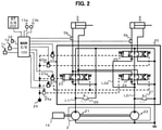
- Fig. 2 is a configuration diagram showing a hydraulic drive system for the construction machine including the first embodiment of the construction machine according to the present invention.
- the hydraulic drive system will be described while assuming that the hydraulic drive system is configured with only the boom cylinder 5 and the arm cylinder 6 as the hydraulic actuators, and a drain circuit and the like that are of no direct relevance to the embodiments of the present invention will not be shown in Fig. 2 and not described.
- a load check valve and the like similar in configuration and behavior to those provided in a conventional hydraulic drive system will not be described, either.
- the hydraulic drive system includes the hydraulic pump device 2, the boom cylinder 5 that serves as a first hydraulic actuator, the arm cylinder 6 that serves as a second hydraulic actuator, the right operation lever device 1c, the left operation lever device 1d, the control valve 20, the main controller 100, and an information controller 200.
- the hydraulic pump device 2 includes a first hydraulic pump 21 and a second hydraulic pump 22.
- the first hydraulic pump 21 and the second hydraulic pump 22 are driven by the engine 14, and deliver hydraulic fluids to a first pump line L1 and a second pump line L2, respectively. While the first hydraulic pump 21 and the second hydraulic pump 22 will be described as fixed displacement hydraulic pumps in the present embodiment, the present invention is not limited to this and the hydraulic pump device 2 may be configured with variable displacement hydraulic pumps.
- the control valve 20 is configured with a dual pump line system composed by the first pump line L1 and the second pump line L2.
- a boom directional control valve 23 that serves as a first directional control valve is connected to the first pump line L1, and the hydraulic fluid delivered by the first hydraulic pump 21 is supplied to the boom cylinder 5.
- a boom speed-up directional control valve 24 that serves as a first speed-up directional control valve and an arm directional control valve 25 that serves as a second directional control valve are connected to the second pump line L2, and the hydraulic fluid delivered by the second hydraulic pump 22 is supplied to the boom cylinder 5 and the arm cylinder 6.
- the boom speed-up directional control valve 24 and the arm directional control valve 25 are configured to be able to divert the hydraulic fluid by a parallel circuit L2a.
- the first pump line L1 and the second pump line L2 are individually provided with relief valves 26 and 27, respectively.
- the relief valve 26 or 27 opens to relieve the hydraulic fluid to a tank.
- the boom directional control valve 23 is driven to move by a pilot hydraulic fluid supplied to a pressure receiving section via solenoid proportional valves 23a and 23b.
- the boom speed-up directional control valve 24 moves by supplying a pilot hydraulic fluid to a pressure receiving section of the boom speed-up directional control valve 24 via solenoid proportional valves 24a and 23b (note that the solenoid proportional valve 23b is also used for moving the boom directional control valve 23), and the arm directional control valve 25 moves by supplying a pilot hydraulic fluid to a pressure receiving section of the arm directional control valve 25 via solenoid proportional valves 25a and 25b.
- solenoid proportional valves 23a, 23b, 24a, 25a, and 25b each output a secondary pilot hydraulic fluid, which is obtained by reducing a pressure of the pilot hydraulic fluid supplied from a pilot hydraulic fluid source 29 as an original pressure at a pressure in response to a command current from the main controller 100, to the directional control valves 23 to 25.
- the right operation lever device 1c outputs, as a boom operation signal, a voltage signal in response to an operation amount and an operation direction of an operation lever to the main controller 100.
- the left operation lever device 1d outputs, as an arm operation signal, a voltage signal in response to an operation amount and an operation direction of an operation lever to the main controller 100.
- the boom cylinder 5 is provided with a boom cylinder bottom-chamber-side pressure sensor 5b that detects a pressure of a bottom-side hydraulic chamber
- the arm cylinder 6 is provided with an arm cylinder bottom-chamber-side pressure sensor 6b that detects a pressure of a bottom-side hydraulic chamber and that serve as an excavation load sensor as in claims.
- the boom cylinder bottom-chamber-side pressure sensor 5b and the arm cylinder bottom-chamber-side pressure sensor 6b each output a detected pressure signal to the main controller 100.
- a mode setting switch 32 is disposed within the operation room, and enables an operator to select whether to enable or disable semiautomatic control in work conducted by the construction machine. That is, either True: the semiautomatic control enabled or False: the semiautomatic control disabled can be selected.
- the main controller 100 inputs a semiautomatic control enable flag transmitted from the mode setting switch 32, target surface information transmitted from the information controller 200, the boom angle signal and the arm angle signal transmitted from the angle sensors 13a and 13b, respectively, and the boom bottom pressure signal and the arm bottom pressure signal transmitted from the boom cylinder bottom-chamber-side pressure sensor 5b and the arm cylinder bottom-chamber-side pressure sensor 6b, respectively.
- the main controller 100 outputs command signals to the solenoid proportional valves 23a, 23b, 24a, 25a, and 25b for driving them respectively in response to these input signals. It is noted that computing performed by the information controller 200 is of no direct relevance to the present invention; thus, a description thereof will be omitted.
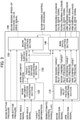
- Fig. 3 is a conceptual diagram showing a configuration of the main controller that configures the first embodiment of the construction machine according to the present invention.
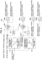
- Fig. 4 is a control block diagram showing an example of computing contents of a main spool control section in the main controller that configures the first embodiment of the construction machine according to the present invention.
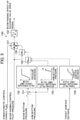
- Fig. 5 is a control block diagram showing an example of computing contents of a boom speed-up control section in the main controller that configures the first embodiment of the construction machine according to the present invention.
- the main controller 100 includes a target pilot pressure computing section 110, a work implement position acquisition section 120, a target surface distance acquisition section 130, a main spool control section 140, and a boom speed-up control section 150.
- the target pilot pressure computing section 110 input the boom operation amount signal from the right operation lever device 1c and the arm operation amount signal from the left operation lever device 1d.
- the target pilot pressure computing section 110 computes a boom raising target pilot pressure, a boom lowering target pilot pressure, an arm crowding target pilot pressure, and an arm dumping target pilot pressure in response to the input signals, and outputs the computed pressures to the main spool control section 140.
- the boom raising target pilot pressure is set higher as a boom operation amount is larger in a boom raising direction
- the boom lowering target pilot pressure is set higher as the boom operation amount is larger in a boom lowering direction.
- the arm crowding target pilot pressure is set higher as an arm operation amount is larger in an arm crowding direction
- the arm dumping target pilot pressure is set higher as the arm operation amount is larger in an arm dumping direction.
- the work implement position acquisition section 120 inputs the boom angle signal and the arm angle signal from the angle sensors 13a and 13b, computes a tip end position of the bucket 8 in response to the input signals by using preset geometric information on the boom 11 and the arm 12, and outputs the computed tip end position, as a work implement position signal, to the target surface distance acquisition section 130.
- the work implement position is computed as, for example, one point on a coordinate system fixed to the construction machine.
- the work implement position is not limited to this but may be computed as a plurality of point groups taking into account the shape of the work implement 15.
- the work implement position acquisition section 120 may perform computing similar to that performed by the locus controller for the construction machine described in Patent Document 1.
- the target surface distance acquisition section 130 inputs the target surface information transmitted from the information controller 200 and the work implement position signal from the work implement position acquisition section 120, computes a distance between the work implement 15 and a construction target surface (hereinafter, referred to as target surface distance), and outputs the target surface distance to the main spool control section 140 and the boom speed-up control section 150.
- target surface distance a distance between the work implement 15 and a construction target surface (hereinafter, referred to as target surface distance)
- the target surface information is given as, for example, two points on a two-dimensional plane coordinate system fixed to the construction machine.
- the target surface information is not limited to this but may be given as three points that configure a plane on a global three-dimensional coordinate system. In the latter case, however, it is required to perform coordinate transformation from the three-dimensional coordinate system into a coordinate system same as that on which the work implement position is defined.
- the target surface distance acquisition section 130 may compute the target surface distance using a point closest to the target surface information.
- the target surface distance acquisition section 130 may perform computing similar to that performed by the locus controller for the construction machine described in Patent Document 1 to compute a shortest distance ⁇ h.
- the main spool control section 140 inputs the semiautomatic control enable flag transmitted from the mode setting switch 32, the boom raising target pilot pressure, the boom lowering target pilot pressure, the arm crowding target pilot pressure, and the arm dumping target pilot pressure from the target pilot pressure computing section 110, and a target surface distance signal from the target surface distance acquisition section 130.
- the main spool control section 140 When the semiautomatic control enable flag is True, the main spool control section 140 performs computing to correct the target pilot pressures in response to the target surface distance, computes a boom raising solenoid valve drive signal, a boom lowering solenoid valve drive signal, an arm crowding solenoid valve drive signal, and an arm dumping solenoid valve drive signal, and outputs these signals as drive signals for driving the solenoid proportional valves 23a, 23b, 25a, and 25b corresponding to the drive signals. Details of the computing performed by the main spool control section 140 will be described later.
- the boom speed-up control section 150 inputs the semiautomatic control enable flag transmitted from the mode setting switch 32, a boom raising control pilot pressure from the main spool control section 140, the target surface distance signal from the target surface distance acquisition section 130, the boom cylinder bottom-side hydraulic chamber pressure signal (hereinafter, also referred to as boom bottom pressure signal) and the arm cylinder bottom-side hydraulic chamber pressure signal (hereinafter, also referred to as arm bottom pressure signal) transmitted from the pressure sensors 5b and 6b, respectively.
- the boom speed-up control section 150 performs computing to correct the boom raising target pilot pressure, computes a boom raising speed-up solenoid valve drive signal, and outputs the drive signal as a drive signal for driving the solenoid proportional valve 24a. Details of the computing performed by the boom speed-up control section 150 will be described later.
- the main spool control section 140 includes a boom raising corrected pilot pressure table 141, a maximum value selector 142, an arm crowding corrected pilot pressure gain table 143, a multiplier 144, selectors 145a and 145c, and solenoid valve drive signal tables 146a, 146b, 146c, and 146d.
- the boom raising corrected pilot pressure table 141 inputs the target surface distance signal, computes a boom raising corrected pilot pressure using a preset table, and outputs the boom raising corrected pilot pressure to the maximum value selector 142.
- the maximum value selector 142 inputs the boom raising target pilot pressure and the boom raising corrected pilot pressure, selects a maximum value between the boom raising target pilot pressure and the boom raising corrected pilot pressure, and outputs the maximum value to a second input terminal of the selector 145a.
- the boom raising corrected pilot pressure table 141 is set such that the boom raising corrected pilot pressure becomes higher as the target surface distance becomes larger in a negative direction, that is, as the work implement 15 gets deeper into the target surface. It is thereby possible to perform a boom raising motion in response to the target surface distance and prevent the work implement 15 from getting into the target surface.
- the selector 145a inputs the boom raising target pilot pressure signal through a first input terminal thereof, an output signal from the maximum value selector 142 described above through the second input terminal, and a semiautomatic control enable flag signal through a switched input terminal thereof.
- the selector 145a selects and outputs the boom raising target pilot pressure signal when the semiautomatic control enable flag signal is False, and selects and outputs the maximum value between the boom raising target pilot pressure signal and the boom raising corrected pilot pressure signal when the semiautomatic control enable flag signal is True.
- An output signal from the selector 145a is outputted, as a boom raising control pilot pressure signal, to the solenoid valve drive signal table 146a and the boom speed-up control section 150.
- the solenoid valve drive signal table 146a computes and outputs the solenoid valve drive signal in response to the input boom raising control pilot pressure signal by using a preset table to drive the solenoid proportional valve 23a.
- the solenoid valve drive signal table 146b computes and outputs the solenoid valve drive signal in response to the input boom raising/lowering target pilot pressure signal by using a preset table to drive the solenoid proportional valve 23b.
- the arm crowding corrected pilot pressure gain table 143 inputs the target surface distance signal, computes an arm crowding corrected pilot pressure gain in response to the target surface distance by using a preset table, and outputs the arm crowding corrected pilot pressure gain to the multiplier 144.
- the multiplier 144 inputs the arm crowding target pilot pressure and the arm crowding corrected pilot pressure gain, multiplies the input arm crowding target pilot pressure by the input arm crowding corrected pilot pressure gain, and outputs a multiplication result to a second input terminal of the selector 145c.
- the arm crowding corrected pilot pressure gain table 143 is set such that the arm crowding corrected pilot pressure becomes lower as the target surface distance becomes larger in the negative direction, that is, as the work implement 15 gets deeper into the target surface. It is thereby possible to reduce an arm crowding speed in response to the target surface distance and prevent the work implement 15 from getting into the target surface.
- the selector 145c inputs the arm crowding target pilot pressure signal through a first input terminal thereof, an output signal from the multiplier 144 described above through the second input terminal, and the semiautomatic control enable flag signal through a switched input terminal thereof.
- the selector 145c selects and outputs the arm crowding target pilot pressure signal when the semiautomatic control enable flag signal is False, and selects and outputs an arm crowding corrected pilot pressure signal obtained by multiplying the arm crowding target pilot pressure signal by the arm crowding corrected pilot pressure gain when the semiautomatic control enable flag signal is True.
- An output signal from the selector 145c is outputted, as the arm crowding control pilot pressure signal, to the solenoid valve drive signal table 146c.
- the solenoid valve drive signal table 146c computes and outputs the solenoid valve drive signal in response to the input arm crowding control pilot pressure signal by using a preset table to drive the solenoid proportional valve 25a.
- the solenoid valve drive signal table 146d computes and outputs the solenoid valve drive signal in response to the input arm dumping target pilot pressure signal by using a preset table to drive the solenoid proportional valve 25b.
- boom raising target pilot pressure and the arm crowding target pilot pressure may be corrected by vector direction correction described in Patent Document 1.
- the boom speed-up control section 150 includes a subtracter 151, a pilot pressure upper limit value table 152, a second pilot pressure upper limit value table 153, a third pilot pressure upper limit value table 154, a maximum value selector 155, a minimum value selector 156, a selector 157, and a solenoid valve drive signal table 158.
- the subtracter 151 inputs the boom bottom pressure signal and the arm bottom pressure signal, computes a pressure deviation by subtracting the arm bottom pressure signal from the boom bottom pressure signal, and outputs the pressure deviation to the pilot pressure upper limit value table 152. It is noted that the pressure deviation getting smaller indicates an increase of an arm bottom pressure relative to a boom bottom pressure, which in turn indicates an increase of an excavation load imposed on the work implement 15.
- the pilot pressure upper limit value table 152 computes a pilot pressure upper limit value in response to the input pressure deviation by using a preset table, and outputs the pilot pressure upper limit value to the maximum value selector 155.
- the pilot pressure upper limit value table 152 is set such that the pilot pressure upper limit value becomes lower as the pressure deviation between the boom bottom pressure signal and the arm bottom pressure signal becomes smaller, that is, the excavation load imposed on the work implement 15 becomes heavier.
- a boom raising speed-up pilot pressure delivered by the solenoid proportional valve 24a is suppressed to limit a meter-in opening of the boom speed-up directional control valve 24.
- the second pilot pressure upper limit value table 153 computes a second pilot pressure upper limit value in response to the input arm bottom pressure signal by using a preset table, and outputs the second pilot pressure upper limit value to the maximum value selector 155.
- the second pilot pressure upper limit value table 153 is set such that the second pilot pressure upper limit value becomes higher as the arm bottom pressure signal becomes higher. It is noted that the arm bottom pressure indicated by a dotted line A in Fig. 5 is approximately identical to the relief pressure and that the second pilot pressure upper limit value is raised up to a maximum value before the arm bottom pressure becomes approximately identical to the relief pressure.
- the boom raising speed-up pilot pressure delivered by the solenoid proportional valve 24a is increased to enlarge the meter-in opening of the boom speed-up directional control valve 24. It is, therefore, possible to divert the hydraulic fluid from the second hydraulic pump 22 to the boom cylinder 5 and avoid a relief-caused loss.
- the meter-in opening of the boom speed-up directional control valve 24 is limited to keep the speed balance between the arm cylinder 6 and the boom cylinder 5.
- the third pilot pressure upper limit value table 154 inputs the target surface distance signal, computes a third pilot pressure upper limit value using a preset table, and outputs the third pilot pressure upper limit value to the maximum value selector 155.
- the third pilot pressure upper limit value table 154 is set such that the second pilot pressure upper limit value becomes higher as the target surface distance becomes larger. This setting makes it possible to ensure the diversion of the hydraulic fluid from the second hydraulic pump 22 to the boom cylinder 5 and avoid the relief-caused loss when the work implement 15 is at a distant position from the target surface.
- the maximum value selector 155 inputs the pilot pressure upper limit value, the second pilot pressure upper limit value, and the third pilot pressure upper limit value, corrects the pilot pressure upper limit value by selecting a maximum value among the pilot pressure upper limit value, the second pilot pressure upper limit value, and the third pilot pressure upper limit value, and outputs the corrected pilot pressure upper limit value to the minimum value selector 156.
- the minimum value selector 156 inputs the boom raising control pilot pressure generated by operator's lever operation and the pilot pressure upper limit value from the maximum value selector 155, corrects the boom raising control pilot pressure by selecting a minimum value between the boom raising control pilot pressure and the pilot pressure upper limit value, and outputs the corrected boom raising control pilot pressure to a second input terminal of the selector 157.
- the selector 157 inputs the boom raising control pilot pressure signal through a first input terminal thereof, an output signal from the minimum value selector 156 described above through the second input terminal, and the semiautomatic control enable flag signal through a switched input terminal thereof.
- the selector 157 selects and outputs the boom raising control pilot pressure signal when the semiautomatic control enable flag signal is False, and selects and outputs a value obtained by correcting the boom raising control pilot pressure in response to the boom bottom pressure, the arm bottom pressure, and the target surface distance when the semiautomatic control enable flag signal is True.
- An output signal from the selector 157 is outputted to the solenoid valve drive signal table 158.
- the solenoid valve drive signal table 158 computes and outputs the boom raising speed-up solenoid valve drive signal in response to the boom raising control pilot pressure by using a preset table to drive the solenoid proportional valve 24a.
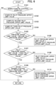
- Fig. 6 is a flowchart showing an example of a flow of computing by the boom speed-up control section in the main controller that configures the first embodiment of the construction machine according to the present invention.
- the boom speed-up control section 150 in the main controller 100 determines whether the semiautomatic control is enabled or disabled (Step S101). Specifically, the boom speed-up control section 150 determines whether the semiautomatic control enable flag signal is True or False. When the semiautomatic control enable flag signal is True, the flow goes to (Step S102); otherwise, the flow goes to RETURN.
- the boom speed-up control section 150 computes the pilot pressure upper limit value, the second pilot pressure upper limit value, and the third pilot pressure upper limit value (Steps S102, S103, and S104). Specifically, the pilot pressure upper limit value table 152, the second pilot pressure upper limit value table 153, and the third pilot pressure upper limit value table 154 execute the computing.
- the boom speed-up control section 150 determines whether the pilot pressure upper limit value exceeds the second pilot pressure upper limit value or not (Step S105). When the pilot pressure upper limit value exceeds the second pilot pressure upper limit value, the flow goes to (Step S107); otherwise, the flow goes to (Step S106).
- Step S105 When the pilot pressure upper limit value does not exceed the second pilot pressure upper limit value in (Step S105), the boom speed-up control section 150 sets the pilot pressure upper limit value to the second pilot pressure upper limit value (Step S106). The flow then goes to (Step S107) .
- the boom speed-up control section 150 determines whether the pilot pressure upper limit value exceeds the third pilot pressure upper limit value (Step S107). When the pilot pressure upper limit value exceeds the third pilot pressure upper limit value, the flow goes to (Step S109); otherwise, the flow goes to (Step S108).
- the boom speed-up control section 150 sets the pilot pressure upper limit value to the third pilot pressure upper limit value (Step S108). The flow then goes to (Step S109).
- the boom speed-up control section 150 determines whether the boom raising control pilot pressure is lower than the pilot pressure upper limit value (Step S109). When the boom raising control pilot pressure is lower than the pilot pressure upper limit value, the flow goes to RETURN and the boom raising speed-up solenoid valve 24a is controlled in response to the boom raising control pilot pressure. In this case, controlling a driving amount of the boom speed-up directional control valve 24 depending on the excavation load or the like, which is characteristic of the present invention, is not executed. When the boom raising control pilot pressure is not lower than the pilot pressure upper limit value, the flow goes to (Step S110).
- the boom speed-up control section 150 sets the boom raising control pilot pressure to the pilot pressure upper limit value (Step S110). Specifically, the boom raising speed-up solenoid valve 24a is controlled in response to the pilot pressure upper limit value. As a result, the controlling the driving amount of the boom speed-up directional control valve 24 depending on the excavation load or the like is executed; thus, it is possible to suppress the diversion and prevent the deviation from the target locus while avoiding the relief-caused loss even when the excavation load increases.
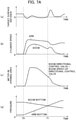
- Fig. 7A is a characteristic diagram showing an example of time-series behavior of a conventional construction machine.
- Fig. 7B is a characteristic diagram showing an example of time-series actions of the construction machine in the first embodiment of the construction machine according to the present invention.
- Fig. 7A shows an example of a case in which the boom directional control valve 23 and the boom speed-up directional control valve 24 are driven by the same pilot pressure
- Fig. 7B shows an example of a case in which the boom directional control valve 23 and the boom speed-up directional control valve 24 are driven by individual pilot pressures.
- a horizontal axis indicates time
- a vertical axis indicates the target surface distance in (a), a cylinder speed in (b), a meter-in opening area in (c), and the arm bottom pressure and the cylinder bottom pressure in (d).
- the target surface distance means the distance from the work implement 15 to the construction target surface.
- time T1 indicates time at which the arm bottom pressure of the arm cylinder 6 becomes higher than the boom bottom pressure of the boom cylinder 5.
- Fig. 7B the construction machine behaves similarly to that in a case of Fig. 7A before time T1'.
- the meter-in opening area of the boom speed-up directional control valve 24 decreases as shown in (c); thus, the diversion amount of the hydraulic fluid passing through the boom speed-up directional control valve 24 does not increase. This can keep the balance between the boom cylinder speed and the arm cylinder speed as shown in (b).
- the second directional control valve and the first speed-up directional control valve are configured to be able to divert the hydraulic fluid and the driving amount of the first speed-up directional control valve is controlled in response to the excavation load. Therefore, even when the excavation load increases, it is possible to suppress the diversion and prevent the deviation from the target locus while avoiding the relief-caused loss. As a consequence, it is possible to ensure predetermined finishing precision.
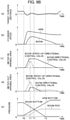
- FIG. 8A is an opening characteristic diagram showing an example of opening characteristics of the boom directional control valve and the boom speed-up directional control valve in the conventional construction machine.
- Fig. 8B is an opening characteristic diagram showing an example of opening characteristics of the boom directional control valve and the boom speed-up directional control valve that configure the second embodiment of the construction machine according to the present invention.
- While a configuration of a hydraulic drive system in the second embodiment of the construction machine according to the present invention is generally the same as that in the first embodiment, the second embodiment differs from the first embodiment in that opening area characteristics for the pilot pressures are changed from ordinary characteristics according to the conventional technique.
- FIG. 8A shows a boom raising-side opening area of the boom directional control valve 23 for the boom raising pilot pressure in the conventional construction machine, and (b) shows a boom raising-side opening area of the boom speed-up directional control valve 24 for the boom raising speed-up pilot pressure in the conventional construction machine.
- Fig. 8B shows a boom raising-side opening area of the boom directional control valve 23 for the boom raising pilot pressure in the second embodiment of the present invention, and (b) shows a boom raising-side opening area of the boom speed-up directional control valve 24 for the boom raising speed-up pilot pressure in the second embodiment of the present invention.
- a solid line indicates meter-in opening area characteristics and a broken line indicates meter-out opening area characteristics.
- the boom directional control valve 23 and the boom speed-up directional control valve 24 are generally set such that meter-in opening areas and meter-out opening areas open simultaneously for the respective boom raising pilot pressures.
- the boom directional control valve 23 is set such that the meter-in opening area starts to increase earlier than the meter-out opening area for the boom raising pilot pressure as shown in (a) of Fig. 8B .
- the boom speed-up directional control valve 24 is set such that the meter-out opening area starts to increase earlier than the meter-in opening area for the boom raising speed-up pilot pressure as shown in (b) of Fig. 8B .
- the boom directional control valve 23 and the boom speed-up directional control valve 24 are set such that the meter-out opening area of the boom speed-up directional control valve 24 starts to increase earlier than the meter-out opening area of the boom directional control valve 23.
- the pilot pressure at which the boom speed-up directional control valve 24 starts to open is set to a lower value than the pilot pressure at which the boom directional control valve 23 starts to open.
- a total meter-out opening area in the present embodiment is smaller than that in the conventional technique.
- the meter-out opening area of the boom speed-up directional control valve 24 can be reduced simultaneously with closing of the meter-in opening thereof; thus, it is possible to increase a boom rod pressure.
- This can prevent a reduction of the load pressure of the boom cylinder 5 in an extension direction thereof due to the excavation reaction force and, therefore, keep the speed balance between the arm cylinder 6 and the boom cylinder 5. As a consequence, it is possible to attain predetermined finishing precision.
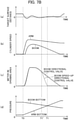
- Fig. 9A is a characteristic diagram showing an example of time-series behavior of the construction machine to which directional control valves having conventional opening area characteristics are applied in the second embodiment of the construction machine according to the present invention.
- Fig. 9B is a characteristic diagram showing an example of time-series behavior of the construction machine in the second embodiment of the construction machine according to the present invention.
- a horizontal axis indicates time
- a vertical axis indicates the target surface distance in (a), the cylinder speed in (b), the meter-in opening area in (c), the meter-out opening area in (d), and the arm bottom pressure and the cylinder bottom pressure in (e).
- the target surface distance means the distance from the work implement 15 to the construction target surface.
- time T1 indicates time at which the arm bottom pressure of the arm cylinder 6 becomes higher than the boom bottom pressure of the boom cylinder 5
- time T2 indicates time at which the boom bottom pressure of the boom cylinder 5 becomes approximately 0.
- Fig. 9A when the excavation starts at time T0, then the hydraulic fluid is supplied to the arm cylinder 6, and the arm cylinder speed increases as shown in (b).
- the meter-in openings of the boom directional control valve 23 and the boom speed-up directional control valve 24 sequentially open as shown in (c)
- the hydraulic fluid is supplied to the boom cylinder 5, and the boom cylinder speed increases.
- the meter-out openings of the boom directional control valve 23 and the boom speed-up directional control valve 24 sequentially open as shown in (d), and a rod-side pressure of the boom cylinder 5 (hereinafter, referred to as boom rod pressure) in response to the opening areas and the boom cylinder speed is generated as shown in (e).
- An increase of the boom cylinder speed enables the work implement 15 to move along the construction target surface to keep the target surface distance at around 0 as shown in (a).
- the arm bottom pressure increases by the excavation reaction force and the boom bottom pressure decreases conversely.
- the pilot pressure acting on the boom speed-up directional control valve 24 is limited as described above.
- the meter-in opening area of the boom speed-up directional control valve 24 decreases as shown in (c); thus, the diversion amount of the hydraulic fluid passing through the boom speed-up directional control valve 24 does not increase, and the balance is kept between the boom cylinder speed and the arm cylinder speed as shown in (b).
- the meter-out opening area of the boom speed-up directional control valve 24 also decreases as shown in (d).
- the meter-out opening area of the boom directional control valve 23 is relatively large and the total meter-out opening area, therefore, becomes relatively large; thus, an increment of the boom rod pressure shown in (e) is small.
- the boom cylinder 5 starts to extend at a speed equal to or higher than a flow rate of the supplied hydraulic fluid.
- the target surface distance shown in (a) increases. In other words, a problem occurs that the work implement 15 moves away from the construction target surface.
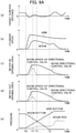
- Fig. 9B the construction machine behaves similarly to that in a case of Fig. 9A before time T1'.
- the meter-in opening areas shown in (c) behaves similarly to that in the case of Fig. 9A from time T1' to time T1, too.
- the meter-out opening area of the boom speed-up directional control valve 24 greatly decreases as shown in (d). Since the construction machine is configured such that the meter-out opening area of the boom speed-up directional control valve 24 is relatively large to the meter-out opening area of the boom directional control valve 23, the total meter-out opening area of the two valves becomes relatively small. The boom rod pressure thereby increases relatively greatly as shown in (e).
- the boom bottom pressure further decreases by the excavation reaction force and reaches approximately 0.
- the boom rod pressure is relatively high as shown in (e); thus, it is possible to prevent the boom cylinder 5 from extending at the speed equal to or higher than the flow rate of the supplied hydraulic fluid as shown in (b). As a result, the target surface distance is kept around 0 as shown in (a).
- the second embodiment of the construction machine according to the present invention described above can attain similar effects to those of the first embodiment.
- the present invention is not limited to the embodiments described above but encompasses various modifications.
- the present invention has been described while the boom cylinder 5 and the arm cylinder 6 are taken as an example in the above embodiments; however, the present invention is not limited to this.
Applications Claiming Priority (2)
| Application Number | Priority Date | Filing Date | Title |
|---|---|---|---|
| JP2016070130A JP6495857B2 (ja) | 2016-03-31 | 2016-03-31 | 建設機械 |
| PCT/JP2016/084103 WO2017168822A1 (ja) | 2016-03-31 | 2016-11-17 | 建設機械 |
Publications (3)
| Publication Number | Publication Date |
|---|---|
| EP3438468A1 EP3438468A1 (en) | 2019-02-06 |
| EP3438468A4 EP3438468A4 (en) | 2020-05-20 |
| EP3438468B1 true EP3438468B1 (en) | 2022-01-26 |
Family
ID=59962878
Family Applications (1)
| Application Number | Title | Priority Date | Filing Date |
|---|---|---|---|
| EP16897038.2A Active EP3438468B1 (en) | 2016-03-31 | 2016-11-17 | Construction machine with speed-up control section |
Country Status (6)
| Country | Link |
|---|---|
| US (1) | US10633825B2 (ja) |
| EP (1) | EP3438468B1 (ja) |
| JP (1) | JP6495857B2 (ja) |
| KR (1) | KR102110887B1 (ja) |
| CN (1) | CN108368861B (ja) |
| WO (1) | WO2017168822A1 (ja) |
Families Citing this family (18)
| Publication number | Priority date | Publication date | Assignee | Title |
|---|---|---|---|---|
| JP6633464B2 (ja) * | 2016-07-06 | 2020-01-22 | 日立建機株式会社 | 作業機械 |
| JP6707064B2 (ja) * | 2017-08-24 | 2020-06-10 | 日立建機株式会社 | 油圧式作業機械 |
| JP6966312B2 (ja) * | 2017-12-14 | 2021-11-10 | 日立建機株式会社 | 作業機械 |
| JP6817457B2 (ja) * | 2018-03-15 | 2021-01-20 | 日立建機株式会社 | 作業機械 |
| CN109083223B (zh) * | 2018-07-27 | 2023-11-21 | 山东临工工程机械有限公司 | 远程遥控装载机的液压系统 |
| JP7141894B2 (ja) * | 2018-09-05 | 2022-09-26 | 日立建機株式会社 | 作業機械 |
| JP7149140B2 (ja) * | 2018-09-18 | 2022-10-06 | 川崎重工業株式会社 | マルチコントロールバルブユニット及び油圧ショベル用油圧駆動装置 |
| JP7283910B2 (ja) * | 2019-02-01 | 2023-05-30 | 株式会社小松製作所 | 建設機械の制御システム、建設機械、及び建設機械の制御方法 |
| JP7268435B2 (ja) * | 2019-03-22 | 2023-05-08 | コベルコ建機株式会社 | 作業機械の油圧駆動装置 |
| JP7370724B2 (ja) * | 2019-04-05 | 2023-10-30 | 株式会社竹内製作所 | 作業用車両の作動制御装置 |
| JP7253478B2 (ja) * | 2019-09-25 | 2023-04-06 | 日立建機株式会社 | 作業機械 |
| JP2021095775A (ja) * | 2019-12-18 | 2021-06-24 | 株式会社神戸製鋼所 | 作業機械の作業補助装置および作業現場における施工面認識方法 |
| GB2593488A (en) * | 2020-03-24 | 2021-09-29 | Bamford Excavators Ltd | Hydraulic system |
| CN111764459A (zh) * | 2020-07-10 | 2020-10-13 | 三一重机有限公司 | 挖掘机的液压泵的启动控制方法 |
| CN112482485A (zh) * | 2020-11-10 | 2021-03-12 | 徐州徐工挖掘机械有限公司 | 执行机构轨迹控制方法、装置、控制器以及存储介质 |
| JP7444032B2 (ja) | 2020-11-16 | 2024-03-06 | コベルコ建機株式会社 | 建設機械 |
| JP2022154940A (ja) * | 2021-03-30 | 2022-10-13 | 株式会社小松製作所 | 油圧ショベルの油圧システム、油圧ショベル、及び油圧ショベルの制御方法 |
| CN113153844B (zh) * | 2021-05-31 | 2023-07-25 | 上海三一重机股份有限公司 | 液压系统及其控制方法、以及作业机械 |
Family Cites Families (21)
| Publication number | Priority date | Publication date | Assignee | Title |
|---|---|---|---|---|
| DE2656032B2 (de) * | 1976-12-10 | 1979-09-13 | Danfoss A/S, Nordborg (Daenemark) | Hydraulisches System mit mindestens zwei Verbrauchern |
| JP3767914B2 (ja) | 1993-12-27 | 2006-04-19 | 日立建機株式会社 | 油圧建設機械の制御装置 |
| JP3059378B2 (ja) * | 1996-04-17 | 2000-07-04 | 住友建機株式会社 | 油圧ショベルの制御回路 |
| JP3571142B2 (ja) | 1996-04-26 | 2004-09-29 | 日立建機株式会社 | 建設機械の軌跡制御装置 |
| JP3165048B2 (ja) * | 1996-12-19 | 2001-05-14 | 住友建機株式会社 | 油圧ショベル制御回路 |
| JPH11131532A (ja) * | 1997-10-28 | 1999-05-18 | Shin Caterpillar Mitsubishi Ltd | 建設機械の制御回路 |
| JP4209705B2 (ja) * | 2003-03-17 | 2009-01-14 | 日立建機株式会社 | 作業機の油圧回路 |
| JP4410512B2 (ja) * | 2003-08-08 | 2010-02-03 | 日立建機株式会社 | 油圧駆動装置 |
| KR100601458B1 (ko) * | 2004-12-16 | 2006-07-18 | 두산인프라코어 주식회사 | 굴삭기의 붐-암 복합동작 유압제어장치 |
| JP2007024103A (ja) * | 2005-07-13 | 2007-02-01 | Hitachi Constr Mach Co Ltd | 油圧駆動装置 |
| JP2007100779A (ja) * | 2005-10-03 | 2007-04-19 | Kayaba Ind Co Ltd | 油圧制御装置 |
| JP5275187B2 (ja) * | 2009-09-17 | 2013-08-28 | 住友建機株式会社 | 建設機械の油圧回路 |
| KR101652112B1 (ko) * | 2009-12-23 | 2016-08-29 | 두산인프라코어 주식회사 | 하이브리드 굴삭기 붐 구동시스템 및 그 제어방법 |
| JP5647052B2 (ja) * | 2011-03-25 | 2014-12-24 | 日立建機株式会社 | ハイブリッド式建設機械 |
| JP5356477B2 (ja) | 2011-09-06 | 2013-12-04 | 住友建機株式会社 | 建設機械 |
| JP5938356B2 (ja) | 2013-02-22 | 2016-06-22 | 日立建機株式会社 | 油圧ショベルの油圧駆動装置 |
| CN203614479U (zh) * | 2013-11-08 | 2014-05-28 | 宣化钢铁集团有限责任公司 | 一种具有高同步精度的中间包升降液压装置 |
| CN106104012B (zh) * | 2014-03-11 | 2019-07-23 | 住友重机械工业株式会社 | 挖土机 |
| US20170121930A1 (en) * | 2014-06-02 | 2017-05-04 | Komatsu Ltd. | Construction machine control system, construction machine, and method of controlling construction machine |
| CN204729370U (zh) * | 2015-07-02 | 2015-10-28 | 四川海洋特种技术研究所 | 一种水下液压系统浅水测试装置用液压动力单元 |
| US9834905B2 (en) * | 2015-09-25 | 2017-12-05 | Komatsu Ltd. | Work machine control device, work machine, and work machine control method |
-
2016
- 2016-03-31 JP JP2016070130A patent/JP6495857B2/ja active Active
- 2016-11-17 KR KR1020187014982A patent/KR102110887B1/ko active IP Right Grant
- 2016-11-17 CN CN201680070727.4A patent/CN108368861B/zh active Active
- 2016-11-17 US US16/074,132 patent/US10633825B2/en active Active
- 2016-11-17 EP EP16897038.2A patent/EP3438468B1/en active Active
- 2016-11-17 WO PCT/JP2016/084103 patent/WO2017168822A1/ja active Application Filing
Also Published As
| Publication number | Publication date |
|---|---|
| EP3438468A4 (en) | 2020-05-20 |
| CN108368861A (zh) | 2018-08-03 |
| JP6495857B2 (ja) | 2019-04-03 |
| US20190338494A1 (en) | 2019-11-07 |
| EP3438468A1 (en) | 2019-02-06 |
| KR102110887B1 (ko) | 2020-05-14 |
| US10633825B2 (en) | 2020-04-28 |
| JP2017180712A (ja) | 2017-10-05 |
| KR20180075624A (ko) | 2018-07-04 |
| WO2017168822A1 (ja) | 2017-10-05 |
| CN108368861B (zh) | 2019-10-18 |
Similar Documents
| Publication | Publication Date | Title |
|---|---|---|
| EP3438468B1 (en) | Construction machine with speed-up control section | |
| CN110392755B (zh) | 液压式作业机械 | |
| US10436229B2 (en) | Hydraulic drive system for work machine | |
| US10227997B2 (en) | Hydraulic drive system for work machine | |
| JP6545609B2 (ja) | 油圧建設機械の制御装置 | |
| US10563378B2 (en) | Hydraulic system for work machines | |
| US10526767B2 (en) | Construction machine | |
| US9951797B2 (en) | Work machine | |
| JP6807290B2 (ja) | 作業機械 | |
| US11286644B2 (en) | Hydraulic actuator for excavation work machine | |
| US11060261B2 (en) | Slewing hydraulic work machine | |
| US10889964B2 (en) | Drive system for construction machine | |
| JP6782852B2 (ja) | 建設機械 | |
| US20220364337A1 (en) | Construction Machine | |
| JP2013249900A (ja) | 油圧駆動回路 |
Legal Events
| Date | Code | Title | Description |
|---|---|---|---|
| STAA | Information on the status of an ep patent application or granted ep patent |
Free format text: STATUS: THE INTERNATIONAL PUBLICATION HAS BEEN MADE |
|
| PUAI | Public reference made under article 153(3) epc to a published international application that has entered the european phase |
Free format text: ORIGINAL CODE: 0009012 |
|
| STAA | Information on the status of an ep patent application or granted ep patent |
Free format text: STATUS: REQUEST FOR EXAMINATION WAS MADE |
|
| 17P | Request for examination filed |
Effective date: 20181031 |
|
| AK | Designated contracting states |
Kind code of ref document: A1 Designated state(s): AL AT BE BG CH CY CZ DE DK EE ES FI FR GB GR HR HU IE IS IT LI LT LU LV MC MK MT NL NO PL PT RO RS SE SI SK SM TR |
|
| AX | Request for extension of the european patent |
Extension state: BA ME |
|
| STAA | Information on the status of an ep patent application or granted ep patent |
Free format text: STATUS: REQUEST FOR EXAMINATION WAS MADE |
|
| DAV | Request for validation of the european patent (deleted) | ||
| DAX | Request for extension of the european patent (deleted) | ||
| A4 | Supplementary search report drawn up and despatched |
Effective date: 20200421 |
|
| RIC1 | Information provided on ipc code assigned before grant |
Ipc: E02F 3/43 20060101ALI20200415BHEP Ipc: E02F 9/22 20060101ALI20200415BHEP Ipc: F15B 11/02 20060101ALI20200415BHEP Ipc: F15B 11/044 20060101ALI20200415BHEP Ipc: F15B 11/17 20060101ALI20200415BHEP Ipc: F15B 11/08 20060101ALI20200415BHEP Ipc: E02F 9/20 20060101ALI20200415BHEP Ipc: F15B 11/028 20060101AFI20200415BHEP |
|
| RIC1 | Information provided on ipc code assigned before grant |
Ipc: E02F 9/20 20060101ALI20210715BHEP Ipc: F15B 11/17 20060101ALI20210715BHEP Ipc: F15B 11/08 20060101ALI20210715BHEP Ipc: F15B 11/044 20060101ALI20210715BHEP Ipc: F15B 11/02 20060101ALI20210715BHEP Ipc: E02F 9/22 20060101ALI20210715BHEP Ipc: E02F 3/43 20060101ALI20210715BHEP Ipc: F15B 11/028 20060101AFI20210715BHEP |
|
| GRAP | Despatch of communication of intention to grant a patent |
Free format text: ORIGINAL CODE: EPIDOSNIGR1 |
|
| STAA | Information on the status of an ep patent application or granted ep patent |
Free format text: STATUS: GRANT OF PATENT IS INTENDED |
|
| INTG | Intention to grant announced |
Effective date: 20210917 |
|
| RIN1 | Information on inventor provided before grant (corrected) |
Inventor name: TSURUGA YASUTAKA Inventor name: TANAKA HIROAKI Inventor name: SAKAMOTO HIROSHI Inventor name: MORIKI HIDEKAZU |
|
| GRAS | Grant fee paid |
Free format text: ORIGINAL CODE: EPIDOSNIGR3 |
|
| GRAA | (expected) grant |
Free format text: ORIGINAL CODE: 0009210 |
|
| STAA | Information on the status of an ep patent application or granted ep patent |
Free format text: STATUS: THE PATENT HAS BEEN GRANTED |
|
| AK | Designated contracting states |
Kind code of ref document: B1 Designated state(s): AL AT BE BG CH CY CZ DE DK EE ES FI FR GB GR HR HU IE IS IT LI LT LU LV MC MK MT NL NO PL PT RO RS SE SI SK SM TR |
|
| REG | Reference to a national code |
Ref country code: GB Ref legal event code: FG4D |
|
| REG | Reference to a national code |
Ref country code: CH Ref legal event code: EP |
|
| REG | Reference to a national code |
Ref country code: AT Ref legal event code: REF Ref document number: 1465493 Country of ref document: AT Kind code of ref document: T Effective date: 20220215 |
|
| REG | Reference to a national code |
Ref country code: IE Ref legal event code: FG4D |
|
| REG | Reference to a national code |
Ref country code: DE Ref legal event code: R096 Ref document number: 602016068768 Country of ref document: DE |
|
| REG | Reference to a national code |
Ref country code: LT Ref legal event code: MG9D |
|
| REG | Reference to a national code |
Ref country code: NL Ref legal event code: MP Effective date: 20220126 |
|
| REG | Reference to a national code |
Ref country code: AT Ref legal event code: MK05 Ref document number: 1465493 Country of ref document: AT Kind code of ref document: T Effective date: 20220126 |
|
| PG25 | Lapsed in a contracting state [announced via postgrant information from national office to epo] |
Ref country code: NL Free format text: LAPSE BECAUSE OF FAILURE TO SUBMIT A TRANSLATION OF THE DESCRIPTION OR TO PAY THE FEE WITHIN THE PRESCRIBED TIME-LIMIT Effective date: 20220126 |
|
| PG25 | Lapsed in a contracting state [announced via postgrant information from national office to epo] |
Ref country code: SE Free format text: LAPSE BECAUSE OF FAILURE TO SUBMIT A TRANSLATION OF THE DESCRIPTION OR TO PAY THE FEE WITHIN THE PRESCRIBED TIME-LIMIT Effective date: 20220126 Ref country code: RS Free format text: LAPSE BECAUSE OF FAILURE TO SUBMIT A TRANSLATION OF THE DESCRIPTION OR TO PAY THE FEE WITHIN THE PRESCRIBED TIME-LIMIT Effective date: 20220126 Ref country code: PT Free format text: LAPSE BECAUSE OF FAILURE TO SUBMIT A TRANSLATION OF THE DESCRIPTION OR TO PAY THE FEE WITHIN THE PRESCRIBED TIME-LIMIT Effective date: 20220526 Ref country code: NO Free format text: LAPSE BECAUSE OF FAILURE TO SUBMIT A TRANSLATION OF THE DESCRIPTION OR TO PAY THE FEE WITHIN THE PRESCRIBED TIME-LIMIT Effective date: 20220426 Ref country code: LT Free format text: LAPSE BECAUSE OF FAILURE TO SUBMIT A TRANSLATION OF THE DESCRIPTION OR TO PAY THE FEE WITHIN THE PRESCRIBED TIME-LIMIT Effective date: 20220126 Ref country code: HR Free format text: LAPSE BECAUSE OF FAILURE TO SUBMIT A TRANSLATION OF THE DESCRIPTION OR TO PAY THE FEE WITHIN THE PRESCRIBED TIME-LIMIT Effective date: 20220126 Ref country code: ES Free format text: LAPSE BECAUSE OF FAILURE TO SUBMIT A TRANSLATION OF THE DESCRIPTION OR TO PAY THE FEE WITHIN THE PRESCRIBED TIME-LIMIT Effective date: 20220126 Ref country code: BG Free format text: LAPSE BECAUSE OF FAILURE TO SUBMIT A TRANSLATION OF THE DESCRIPTION OR TO PAY THE FEE WITHIN THE PRESCRIBED TIME-LIMIT Effective date: 20220426 |
|
| PG25 | Lapsed in a contracting state [announced via postgrant information from national office to epo] |
Ref country code: PL Free format text: LAPSE BECAUSE OF FAILURE TO SUBMIT A TRANSLATION OF THE DESCRIPTION OR TO PAY THE FEE WITHIN THE PRESCRIBED TIME-LIMIT Effective date: 20220126 Ref country code: LV Free format text: LAPSE BECAUSE OF FAILURE TO SUBMIT A TRANSLATION OF THE DESCRIPTION OR TO PAY THE FEE WITHIN THE PRESCRIBED TIME-LIMIT Effective date: 20220126 Ref country code: GR Free format text: LAPSE BECAUSE OF FAILURE TO SUBMIT A TRANSLATION OF THE DESCRIPTION OR TO PAY THE FEE WITHIN THE PRESCRIBED TIME-LIMIT Effective date: 20220427 Ref country code: FI Free format text: LAPSE BECAUSE OF FAILURE TO SUBMIT A TRANSLATION OF THE DESCRIPTION OR TO PAY THE FEE WITHIN THE PRESCRIBED TIME-LIMIT Effective date: 20220126 Ref country code: AT Free format text: LAPSE BECAUSE OF FAILURE TO SUBMIT A TRANSLATION OF THE DESCRIPTION OR TO PAY THE FEE WITHIN THE PRESCRIBED TIME-LIMIT Effective date: 20220126 |
|
| PG25 | Lapsed in a contracting state [announced via postgrant information from national office to epo] |
Ref country code: IS Free format text: LAPSE BECAUSE OF FAILURE TO SUBMIT A TRANSLATION OF THE DESCRIPTION OR TO PAY THE FEE WITHIN THE PRESCRIBED TIME-LIMIT Effective date: 20220526 |
|
| REG | Reference to a national code |
Ref country code: DE Ref legal event code: R097 Ref document number: 602016068768 Country of ref document: DE |
|
| PG25 | Lapsed in a contracting state [announced via postgrant information from national office to epo] |
Ref country code: SM Free format text: LAPSE BECAUSE OF FAILURE TO SUBMIT A TRANSLATION OF THE DESCRIPTION OR TO PAY THE FEE WITHIN THE PRESCRIBED TIME-LIMIT Effective date: 20220126 Ref country code: SK Free format text: LAPSE BECAUSE OF FAILURE TO SUBMIT A TRANSLATION OF THE DESCRIPTION OR TO PAY THE FEE WITHIN THE PRESCRIBED TIME-LIMIT Effective date: 20220126 Ref country code: RO Free format text: LAPSE BECAUSE OF FAILURE TO SUBMIT A TRANSLATION OF THE DESCRIPTION OR TO PAY THE FEE WITHIN THE PRESCRIBED TIME-LIMIT Effective date: 20220126 Ref country code: EE Free format text: LAPSE BECAUSE OF FAILURE TO SUBMIT A TRANSLATION OF THE DESCRIPTION OR TO PAY THE FEE WITHIN THE PRESCRIBED TIME-LIMIT Effective date: 20220126 Ref country code: DK Free format text: LAPSE BECAUSE OF FAILURE TO SUBMIT A TRANSLATION OF THE DESCRIPTION OR TO PAY THE FEE WITHIN THE PRESCRIBED TIME-LIMIT Effective date: 20220126 Ref country code: CZ Free format text: LAPSE BECAUSE OF FAILURE TO SUBMIT A TRANSLATION OF THE DESCRIPTION OR TO PAY THE FEE WITHIN THE PRESCRIBED TIME-LIMIT Effective date: 20220126 |
|
| PG25 | Lapsed in a contracting state [announced via postgrant information from national office to epo] |
Ref country code: AL Free format text: LAPSE BECAUSE OF FAILURE TO SUBMIT A TRANSLATION OF THE DESCRIPTION OR TO PAY THE FEE WITHIN THE PRESCRIBED TIME-LIMIT Effective date: 20220126 |
|
| PLBE | No opposition filed within time limit |
Free format text: ORIGINAL CODE: 0009261 |
|
| STAA | Information on the status of an ep patent application or granted ep patent |
Free format text: STATUS: NO OPPOSITION FILED WITHIN TIME LIMIT |
|
| 26N | No opposition filed |
Effective date: 20221027 |
|
| PG25 | Lapsed in a contracting state [announced via postgrant information from national office to epo] |
Ref country code: SI Free format text: LAPSE BECAUSE OF FAILURE TO SUBMIT A TRANSLATION OF THE DESCRIPTION OR TO PAY THE FEE WITHIN THE PRESCRIBED TIME-LIMIT Effective date: 20220126 |
|
| PG25 | Lapsed in a contracting state [announced via postgrant information from national office to epo] |
Ref country code: MC Free format text: LAPSE BECAUSE OF FAILURE TO SUBMIT A TRANSLATION OF THE DESCRIPTION OR TO PAY THE FEE WITHIN THE PRESCRIBED TIME-LIMIT Effective date: 20220126 |
|
| REG | Reference to a national code |
Ref country code: CH Ref legal event code: PL |
|
| REG | Reference to a national code |
Ref country code: BE Ref legal event code: MM Effective date: 20221130 |
|
| PG25 | Lapsed in a contracting state [announced via postgrant information from national office to epo] |
Ref country code: LI Free format text: LAPSE BECAUSE OF NON-PAYMENT OF DUE FEES Effective date: 20221130 Ref country code: IT Free format text: LAPSE BECAUSE OF FAILURE TO SUBMIT A TRANSLATION OF THE DESCRIPTION OR TO PAY THE FEE WITHIN THE PRESCRIBED TIME-LIMIT Effective date: 20220126 Ref country code: CH Free format text: LAPSE BECAUSE OF NON-PAYMENT OF DUE FEES Effective date: 20221130 |
|
| PG25 | Lapsed in a contracting state [announced via postgrant information from national office to epo] |
Ref country code: LU Free format text: LAPSE BECAUSE OF NON-PAYMENT OF DUE FEES Effective date: 20221117 |
|
| PG25 | Lapsed in a contracting state [announced via postgrant information from national office to epo] |
Ref country code: IE Free format text: LAPSE BECAUSE OF NON-PAYMENT OF DUE FEES Effective date: 20221117 |
|
| PGFP | Annual fee paid to national office [announced via postgrant information from national office to epo] |
Ref country code: GB Payment date: 20230928 Year of fee payment: 8 |
|
| PG25 | Lapsed in a contracting state [announced via postgrant information from national office to epo] |
Ref country code: FR Free format text: LAPSE BECAUSE OF NON-PAYMENT OF DUE FEES Effective date: 20221130 Ref country code: BE Free format text: LAPSE BECAUSE OF NON-PAYMENT OF DUE FEES Effective date: 20221130 |
|
| PGFP | Annual fee paid to national office [announced via postgrant information from national office to epo] |
Ref country code: DE Payment date: 20230929 Year of fee payment: 8 |
|
| PG25 | Lapsed in a contracting state [announced via postgrant information from national office to epo] |
Ref country code: HU Free format text: LAPSE BECAUSE OF FAILURE TO SUBMIT A TRANSLATION OF THE DESCRIPTION OR TO PAY THE FEE WITHIN THE PRESCRIBED TIME-LIMIT; INVALID AB INITIO Effective date: 20161117 |
|
| PG25 | Lapsed in a contracting state [announced via postgrant information from national office to epo] |
Ref country code: CY Free format text: LAPSE BECAUSE OF FAILURE TO SUBMIT A TRANSLATION OF THE DESCRIPTION OR TO PAY THE FEE WITHIN THE PRESCRIBED TIME-LIMIT Effective date: 20220126 |