EP3437897B1 - Rad mit integriertem lenksystem für fahrbare rahmengestelle - Google Patents
Rad mit integriertem lenksystem für fahrbare rahmengestelle Download PDFInfo
- Publication number
- EP3437897B1 EP3437897B1 EP18187400.9A EP18187400A EP3437897B1 EP 3437897 B1 EP3437897 B1 EP 3437897B1 EP 18187400 A EP18187400 A EP 18187400A EP 3437897 B1 EP3437897 B1 EP 3437897B1
- Authority
- EP
- European Patent Office
- Prior art keywords
- wheel
- axle
- wheel hub
- control head
- steering
- Prior art date
- Legal status (The legal status is an assumption and is not a legal conclusion. Google has not performed a legal analysis and makes no representation as to the accuracy of the status listed.)
- Active
Links
Images


Classifications
-
- B—PERFORMING OPERATIONS; TRANSPORTING
- B60—VEHICLES IN GENERAL
- B60B—VEHICLE WHEELS; CASTORS; AXLES FOR WHEELS OR CASTORS; INCREASING WHEEL ADHESION
- B60B33/00—Castors in general ; Anti-clogging castors
- B60B33/02—Castors in general ; Anti-clogging castors with disengageable swivel action, i.e. comprising a swivel locking mechanism
-
- B—PERFORMING OPERATIONS; TRANSPORTING
- B60—VEHICLES IN GENERAL
- B60B—VEHICLE WHEELS; CASTORS; AXLES FOR WHEELS OR CASTORS; INCREASING WHEEL ADHESION
- B60B27/00—Hubs
- B60B27/02—Hubs adapted to be rotatably arranged on axle
-
- B—PERFORMING OPERATIONS; TRANSPORTING
- B60—VEHICLES IN GENERAL
- B60B—VEHICLE WHEELS; CASTORS; AXLES FOR WHEELS OR CASTORS; INCREASING WHEEL ADHESION
- B60B33/00—Castors in general ; Anti-clogging castors
- B60B33/006—Castors in general ; Anti-clogging castors characterised by details of the swivel mechanism
-
- B—PERFORMING OPERATIONS; TRANSPORTING
- B60—VEHICLES IN GENERAL
- B60B—VEHICLE WHEELS; CASTORS; AXLES FOR WHEELS OR CASTORS; INCREASING WHEEL ADHESION
- B60B33/00—Castors in general ; Anti-clogging castors
- B60B33/02—Castors in general ; Anti-clogging castors with disengageable swivel action, i.e. comprising a swivel locking mechanism
- B60B33/028—Castors in general ; Anti-clogging castors with disengageable swivel action, i.e. comprising a swivel locking mechanism being actuated automatically
-
- B—PERFORMING OPERATIONS; TRANSPORTING
- B62—LAND VEHICLES FOR TRAVELLING OTHERWISE THAN ON RAILS
- B62K—CYCLES; CYCLE FRAMES; CYCLE STEERING DEVICES; RIDER-OPERATED TERMINAL CONTROLS SPECIALLY ADAPTED FOR CYCLES; CYCLE AXLE SUSPENSIONS; CYCLE SIDECARS, FORECARS, OR THE LIKE
- B62K21/00—Steering devices
- B62K21/005—Steering pivot axis arranged within the wheel, e.g. for a hub center steering arrangement
-
- B—PERFORMING OPERATIONS; TRANSPORTING
- B60—VEHICLES IN GENERAL
- B60B—VEHICLE WHEELS; CASTORS; AXLES FOR WHEELS OR CASTORS; INCREASING WHEEL ADHESION
- B60B33/00—Castors in general ; Anti-clogging castors
- B60B33/04—Castors in general ; Anti-clogging castors adjustable, e.g. in height; linearly shifting castors
-
- B—PERFORMING OPERATIONS; TRANSPORTING
- B60—VEHICLES IN GENERAL
- B60Y—INDEXING SCHEME RELATING TO ASPECTS CROSS-CUTTING VEHICLE TECHNOLOGY
- B60Y2200/00—Type of vehicle
- B60Y2200/80—Other vehicles not covered by groups B60Y2200/10 - B60Y2200/60
- B60Y2200/83—Perambulators; Buggies; Strollers
-
- B—PERFORMING OPERATIONS; TRANSPORTING
- B62—LAND VEHICLES FOR TRAVELLING OTHERWISE THAN ON RAILS
- B62K—CYCLES; CYCLE FRAMES; CYCLE STEERING DEVICES; RIDER-OPERATED TERMINAL CONTROLS SPECIALLY ADAPTED FOR CYCLES; CYCLE AXLE SUSPENSIONS; CYCLE SIDECARS, FORECARS, OR THE LIKE
- B62K21/00—Steering devices
Definitions
- the invention relates to a wheel for mobile frames with an axle and a wheel hub running around the axle.
- Mobile frameworks in particular prams, joggers and multifunctional children's trailers, are usually steered via swiveling front and/or rear wheels or have non-steerable wheels mounted on rigid forks.
- FIG. 1 shows an embodiment of swiveling front and/or rear wheels and their geometric data.
- the wheel is guided over a fork.
- This fork is mounted pivotably on the steering head (16) relative to the frame via its steering axis (15).
- the caster (19) of the wheels (distance between the contact point of the wheel and the point at which the steering axle (15) hits the ground) is realized by an angled design of the fork relative to the steering axle (15).
- the change of direction of the mobile frame is carried out by the operator exerting force on the control handle laterally to the direction of travel (17), which results in a pivoting movement of the fork and wheels and thus a change in direction of the mobile frame. This pivoting movement is possible due to the overrun (19).
- a positive caster (19) is also necessary to automatically align the wheels in the direction of travel (17).
- the wheel In order to move the mobile frame in all directions, the wheel can be swiveled 360°. In order to achieve this, it is necessary to align the steering head angle (18) (angle between the ground and the steering axis (15) at an angle of approx. 90° perpendicular to the ground. The potential energy of the wheel is the same in each of its swivel positions.
- a steering head angle (18) as shown in figure 1 shown is used greater than 90° (or correspondingly less than 90° if the angle between the ground in the direction of travel behind the wheel and the steering axle).
- a steering head angle (18) greater than 90° a maximum of the potential energy arises at the wheel exactly when the wheel is in the straight-ahead position, which advantageously brings the vehicle into what is known as a stable equilibrium for straight-ahead travel.
- this equilibrium does not exist.
- the swiveling wheels tend at higher speeds, e.g. B. at running speed, to flutter. They move sideways to and fro uncontrollably.
- front wheels are made larger and/or suspended from rigid one- or two-sided forks.
- the wheel is therefore not steerable, but allows a stable directional stability, which z. B. for runners who take their children to run training in a jogger or stroller is necessary.
- Multifunctional children's trailers can e.g. B. can be converted to accommodate larger wheels by means of optionally mountable rigid forks in order to use them as joggers.
- it is only possible to steer mobile frames with rigidly installed wheels by raising the wheels, then turning the mobile frame in the desired direction of travel and setting the wheels down again.
- the advantages of stable straight-line stability are compensated for by the use of one or more larger wheels and a steering system that is not available.
- the invention is based on the use of a wheel with an integrated steering system in which a pivoting/steering movement can be realized within the wheel hub via positive trailing and a steering head angle (18) unequal to 90° and in particular greater than 90°.
- the invention enables the combination of stable straight-line stability, even at higher speeds, and a real steering function.
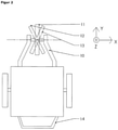
- FIG. 2 shows an embodiment of a mobile frame with an integrated steering system in a plan view.
- the steering process is initiated by the operator.
- a force is exerted laterally to the direction of travel via the operating handle (14) of the mobile frame, which causes the wheel to rotate from its neutral position (11) for a left (12) or right turn (13).
- the operator can reduce the steering force on the operating handle (14) and the wheel moves back to its neutral position (11), i.e. straight-ahead, in a stable manner. This is the case with a neutral weight distribution of the mobile frame and its payload.
- a resetting mechanism is implemented.
- the invention is based on the integration of a steering system within the wheel hub. This means that there is no need for an external rotating fork and steering head construction, which has a positive effect on the overall construction of the mobile frame in a space-saving manner.
- a further advantage of the invention is that the wheel with an integrated steering mechanism can be used on existing products with mobile frames.
- the wheel or wheels with an integrated steering function can be retrofitted to existing wheel mounts. In this way, existing mobile frames can be easily and inexpensively converted.
- FIG. 3 shows an axis (1) in which a pivot pin is received in a bore.
- the bore and the pivot bolt act as the steering head (2) of the steering function.
- the hole in the axle (1) is laid out at a corresponding steering head angle to the ground. This achieves the positive caster of the wheel.
- the axle (1) is provided with a rectangular cross-section at its axle attachment (8), which fixes the axle attachment (8) relative to the axle mount on a fork so that it cannot rotate.
- An annular pivoting element (3) is pivotably attached to the pivot pin.
- the pivoting element (3) is guided over two planar surfaces on the axle (1).
- the pivot pin fixes the pivoting element (3) to the axis (1) and at the same time allows a pivoting movement.
- the ring-shaped design of the pivoting element (3) leaves enough space for pivoting about the steering axis, ie through the bore and axis defined by the steering head bolts.
- the pivoting element (3) accommodates a bearing unit (4) on its outer contour.
- the wheel hub (5) is attached to the bearing unit (4).
- the bearing unit (4) thus enables the wheel hub (5) and thus the wheel to rotate about the axis (1).
- the design allows the entire wheel to swivel around the steering axis via the inner steering head (2).
- a spring element (6) is attached on both sides between the axle (1) and the swivel element (3). Both spring elements (6) are pivotally attached to the pivot element (3) and are guided at the other end through openings in the axle (1). Both spring elements (6) exert an even force on the swivel element (3) and thus on the wheel and thus position the wheel in a vertical neutral position.
- the spring elements (6) can either be designed using rubber-elastic materials or using coil springs or the like.
- both spring elements (6) are designed in such a way that the spring element (6) compresses, but rebound over the defined length of the elastic part of the spring element (6 ) is limited. In this way, both spring elements (6) only exert a restoring force on the pivoting element (3) until the neutral position is reached, without the operator exerting any force.
- the spring preload can be varied depending on the application and axle load.
- a cover disc (7) can be slid onto both sides of the axle (1) to protect the internal components from the effects of moisture and dust.
- FIG 4 shows the wheel with the wheel hub (5), the bearing element (4) and the pivoting element (3) and the pin (20) connecting the axle (1) and the pivoting element (3) as part of the control head (2) in a side view.
- the end (21) of the axle (1) has an angular cross-section with two opposite, essentially horizontally running contact edges (22, 23), which are used to contact, for example, a surface in a dropout of a wheel fork, so that the axle (1) in can be mounted in a defined position in a wheel fork.
- the contact surfaces (22, 23) are at an angle of about 70° to the geometric axis (24) of the bolt (20) in the example shown. If the axle (1) is mounted in a wheel fork in such a way that the contact surfaces (22, 23) run approximately parallel to the ground, there is a caster (19).
- the steering head angle 18 of the in 4 shown configuration of the wheel is about 110 °.
- the wheel can be mounted in a wheel fork in such a way that a suitable caster results.
- Optical markings on the side of the wheel are also conceivable as an assembly aid (for example arrows to indicate where in the direction of travel is in front and where is down), in order to simplify positioning of the axle end or ends in the wheel fork.
Landscapes
- Engineering & Computer Science (AREA)
- Mechanical Engineering (AREA)
- Automatic Cycles, And Cycles In General (AREA)
- Vehicle Body Suspensions (AREA)
- Steering-Linkage Mechanisms And Four-Wheel Steering (AREA)
Description
- Die Erfindung betrifft ein Rad für fahrbare Rahmengestelle mit einer Achse und einer um die Achse umlaufenden Radnabe.
- Fahrbare Rahmengestelle, insbesondere Kinderwagen, Jogger und Multifunktionskinderanhänger, werden üblicherweise über schwenkbare Vorder- und/oder Hinterräder gelenkt oder verfügen über nicht lenkbare an starren Gabeln montierte Räder.
-
Fig. 1 zeigt eine Ausprägung von schwenkbaren Vorder- und/oder Hinterräder und deren geometrischen Daten. - In
Fig. 1 ist das Rad über eine Gabel geführt. Diese Gabel ist relativ zum Rahmen über seine Lenkachse (15) am Steuerkopf (16) schwenkbar gelagert. Der Nachlauf (19) der Räder (Abstand zwischen Aufstandspunkt Rad und dem Punkt in dem die Lenkachse (15) den Boden trifft) wird über eine winkelige Gestaltung der Gabel relativ zur Lenkachse (15) realisiert. Die Richtungsänderung des fahrbaren Rahmengestelles wird durch eine Kraftausübung des Bedieners am Bediengriff seitlich zur Richtung der Fahrt (17) ausgeführt, was zur Folge einer Schwenkbewegung der Gabel und der Räder und somit eine Richtungsänderung des fahrbaren Rahmengestells ermöglicht. Diese Schwenkbewegung ist durch den Nachlauf (19) möglich. Ein positiver Nachlauf (19) ist auch notwendig, um die Räder automatisch in Richtung der Fahrt (17) auszurichten. Um das fahrbare Rahmengestell in alle Richtungen zu bewegen, ist das Rad 360° schwenkbar ausgelegt. Um dies zu realisieren, ist es notwendig den Steuerkopfwinkel (18) (Winkel zwischen Boden und Lenkachse (15) in einen Winkel von ca. 90° senkrecht zum Boden auszurichten. Die potentielle Energie des Rades ist in jeder seiner Schwenkstellungen gleich. - Bei Fahrzeugen, welche für höhere Geschwindigkeiten ausgelegt sind, wie Fahrräder und Motorräder, wird üblicherweise ein Steuerkopfwinkel (18), wie er in
Figur 1 dargestellt ist, größer als 90° eingesetzt (oder dementsprechend kleiner 90°, wenn der Winkel zwischen dem Boden in Fahrtrichtung hinter dem Rad und der Lenkachse). Bei einem Steuerkopfwinkel (18) größer als 90° entsteht am Rad ein Maximum der potentiellen Energie genau in Geradeauslage des Rades, was das Fahrzeug für den Geradeauslauf vorteilhaft in ein sogenanntes stabiles Gleichgewicht bringt. Bei Fahrzeugen und fahrbaren Rahmengestellen mit senkrecht zum Boden ausgelegten Steuerkopfwinkeln (18), wie inFig. 1 dargestellt, ist dieses Gleichgewicht nicht gegeben. Die schwenkbaren Räder neigen bei höheren Geschwindigkeiten, z. B. bei Laufgeschwindigkeit, zum Flattern. Sie bewegen sich unkontrolliert seitlich hin und her. - Ein weiterer Nachteil von schwenkbaren Vorder- und/oder Hinterräder ist, dass die Konstruktion mit außen liegendem Steuerkopf (16) und Steuerkopfhalter relativ viel Platz vorhalten muss. Das vergrößert unnötig den Radstand und damit die Gesamtlänge des fahrbaren Rahmengestells. Speziell bei zusammenklappbaren Kinderwagen und Joggern oder Multifunktionskinderanhängern erhöht das zusätzlich das Packmaß. Um einen Kompromiss zu finden, kommen häufig nur Räder mit kleinem Durchmesser zum Einsatz, z. B. mit einem Außendurchmesser kleiner als 12 Zoll. Der Einsatz von kleinen Rädern führt zu erhöhten Vibrationen bei Fahrten auf nicht asphaltierten Wegen, was wiederum den Einsatzbereich einschränkt.
- Um fahrbare Rahmengestelle als Kompromiss auch bei Geschwindigkeiten über der Schrittgeschwindigkeit komfortabel zu bewegen, werden Vorderräder größer gestaltet und/oder an starren ein- oder zweiseitige Gabeln aufgehängt. Das Rad ist somit nicht lenkbar, ermöglicht aber einen stabilen Geradeauslauf, was z. B. bei Läufern, welche Ihre Kinder zum Lauftraining in einem Jogger oder Sportkinderwagen mitnehmen, notwendig ist. Multifunktionskinderanhänger können z. B. mittels optional montierbaren starren Gabeln für die Aufnahme größerer Räder umgebaut werden, um sie als Jogger zu verwenden. Ein Lenken von fahrbaren Rahmengestellen mit starr eingebauten Rädern ist jedoch nur noch möglich über ein Anheben der Räder, danach Drehen des fahrbaren Rahmengestells in die gewünschte Fahrtrichtung und Wiederabsetzen der Räder. Bei dieser konstruktiven Variante werden die Vorteile eines stabilen Geradeauslaufes durch den Einsatz eines oder mehrerer größerer Räder, durch ein nicht gegebenes Lenksystem wieder kompensiert.
- Die genannten Probleme werden mit einem Rad mit den in Anspruch 1 aufgeführten Merkmalen zumindest teilweise gelöst. Weitere bevorzugte Ausgestaltungen der Erfindungen ergeben sich aus den Unteransprüchen.
- Die Erfindung basiert auf dem Einsatz eines Rades mit einem integrierten Lenksystem, in dem innerhalb der Radnabe eine Schwenk-/Lenkbewegung über einen positiven Nachlauf und einen Steuerkopfwinkel (18) ungleich 90° und insbesondere größer 90° realisiert werden kann. Die Erfindung ermöglicht die Kombination von einem stabilen Geradeauslauf, auch bei höheren Geschwindigkeiten, und einer echten Lenkfunktion.
-
Fig. 2 zeigt eine Ausprägung eines fahrbaren Rahmengestelles mit einem integrierten Lenksystem in einer Draufsicht. - Der Lenkvorgang wird vom Bediener eingeleitet. Über den Bediengriff (14) des fahrbaren Rahmengestelles wird eine Kraft seitlich zur Fahrtrichtung ausgeübt, welche das Rad von seiner Neutralposition (11) in eine Drehbewegung für eine Links- (12) oder Rechtskurve (13) veranlasst. Nach erfolgter Richtungskorrektur kann der Bediener die Lenkkraft am Bediengriff (14) reduzieren und das Rad bewegt sich eigen stabil wieder in seine Neutralposition (11), den Geradeauslauf, zurück. Dies ist bei neutraler Gewichtsverteilung des fahrbaren Rahmengestells und seiner Nutzlast gegeben. Um auch bei nicht neutraler Gewichtsverteilung oder unebenem Gelände einen stabilen Geradeauslauf des Rades zu erzielen, ist in einer vorteilhaften Ausgestaltung der Erfindung gemäß Anspruch 3 ein Rückstellmechanismus realisiert.
- Die Erfindung basiert auf der Integration eines Lenksystems innerhalb der Radnabe. So kann konstruktiv auf eine äußere drehbare Gabel- und Steuerkopfkonstruktion verzichtet werden, was platzsparend auf die Gesamtkonstruktion des fahrbaren Rahmengestells positiv einwirkt. Ein weiterer Vorteil der Erfindung ist, dass das Rad mit integriertem Lenkmechanismus auf bereits bestehende Produkte von fahrbaren Rahmengestellen einsetzbar ist. Das Rad bzw. die Räder mit integrierter Lenkfunktion können in vorhandene Radaufnahmen als Nachrüstung eingebracht werden. So können vorhandene fahrbare Rahmengestelle einfach und kostengünstig umgerüstet werden.
- Ein besonderes bevorzugtes Ausführungsbeispiel wird anhand der
Fig. 3 erläutert. Es zeigen: - Fig. 3
- den Aufbau eines erfindungsgemäßen Rads mit integrierter Lenkung in Schnittdarstellung, Schnitt senkrecht zur Lenkachse; und
- Fig. 4
- das in
Fig. 3 dargestellte Rad in Seitenansicht. -
Fig. 3 zeigt eine Achse (1), in der in einer Bohrung ein Drehbolzen aufgenommen wird. Die Bohrung und der Drehbolzen fungieren als Steuerkopf (2) der Lenkfunktion. Die Bohrung in der Achse (1) wird in einem entsprechenden Steuerkopfwinkel zum Boden ausgelegt. Dadurch wird der positive Nachlauf des Rades erzielt. Um den Steuerkopfwinkel relativ zum Fahrgestell und Boden sicherzustellen, ist die Achse (1) an seiner Achsenbefestigung (8) mit einem rechteckigen Querschnitt versehen, welche die Achsenbefestigung (8) relativ zur Achsaufnahme an einer Gabel verdrehsicher fixiert. Am Drehbolzen ist ein ringförmiges Schwenkelement (3) schwenkbar befestigt. Das Schwenkelement (3) wird über zwei planare Flächen auf der Achse (1) geführt. Der Drehbolzen fixiert dabei das Schwenkelement (3) mit der Achse (1) und lässt gleichzeitig eine Schwenkbewegung zu. Die ringförmige Gestaltung des Schwenkelementes (3) lässt genügend Freiraum zum Schwenken um die Lenkachse, also die durch die Bohrung und den Bolzen des Steuerkopfs definierte Achse. Das Schwenkelement (3) nimmt an seiner äußeren Kontur eine Lagereinheit (4) auf. An der Lagereinheit (4) ist die Radnabe (5) befestigt. Die Lagereinheit (4) ermöglicht so eine Rotationsbewegung der Radnabe (5) und somit des Rades um die Achse (1). Gleichzeitig ermöglicht die Konstruktion über den innen liegenden Steuerkopf (2) das Schwenken des gesamten Rades um die Lenkachse. - Um das gesamte Rad bzw. die Radnabe (5) ohne Krafteinwirkung sicher in seine Neutralposition zu bringen, sind zwischen Achse (1) und dem Schwenkelement (3) zu beiden Seiten jeweils ein Federelement (6) angebracht. Beide Federelemente (6) sind am Schwenkelement (3) schwenkbar angebracht und werden am anderem Ende durch Öffnungen in der Achse (1) geführt. Beide Federelemente (6) üben auf das Schwenkelement (3) und damit auf das Rad eine gleichmäßige Kraft aus und positionieren das Rad somit in einer senkrechten Neutralposition. Die Federelemente (6) können wahlweise über gummi- elastische Materialien ausgeführt werden oder über Schraubenfedern oder Ähnliches. Um stets eine stabile Neutralposition des Rades, ohne Krafteinwirkung des Bedieners, zu erreichen, sind beide Federelemente (6) so ausgeführt, dass ein Einfedern des Federelementes (6) gegeben ist, aber das Ausfedern über die definierte Länge des elastischen Teils des Federelementes (6) begrenzt ist. So üben immer, ohne Krafteinwirkung des Bedieners, beide Federelemente (6) nur so lange eine Rückstellkraft auf das Schwenkelement (3) aus, bis die Neutralposition erreicht ist. Die Federvorspannung kann je nach Anwendungsbereich und Achslast variiert werden. Wahlweise kann eine Abdeckscheibe (7) auf beiden Seiten der Achse (1) aufgeschoben werden, um die inneren Komponenten vor Feuchtigkeit- und Staubeinwirkung zu schützen.
- In
Figur 4 ist das Rad mit der Radnabe (5), dem Lagerelement (4) und dem Schwenkelement (3) und des die Achse (1) und das Schwenkelement (3) verbindenden Bolzens (20) als Bestandteil des Steuerkopfs (2) in Seitenansicht dargestellt. Das Ende (21) der Achse (1) hat einen eckigen Querschnitt mit zwei gegenüberliegenden, im Wesentlichen waagerecht verlaufenden Anlagekanten (22, 23), die zu Anlage beispielsweise einer Fläche in einem Ausfallende einer Radgabel dienen, so dass die Achse (1) in einer definierten Position in einer Radgabel montiert werden kann. Die Anlageflächen (22, 23) stehen in einem Winkel von im dargestellten Beispiel etwa 70° zur geometrischen Achse (24) des Bolzens (20). Wird die Achse (1) so in einer Radgabel montiert, dass die Anlageflächen (22, 23) etwa parallel zum Boden verlaufen, ergibt sich ein Nachlauf (19). Der Steuerkopfwinkel 18 der inFig. 4 dargestellten Konfiguration des Rades beträgt etwa 110°. - Man kann aber ohne weiteres auch auf die Anlageflächen (22, 23) an den Enden der Achse (1) verzichten. Auch ohne derartige Anlageflächen lässt sich das Rad in einer Radgabel so montieren, dass sich ein geeigneter Nachlauf ergibt. Als Montagehilfe sind auch optische Markierungen an der Seite des Rades denkbar (beispielsweise Pfeile zur Anzeige, wo in Fahrtrichtung vorn und wo unten ist), um eine Positionierung des oder der Achsenden in der Radgabel zu vereinfachen.
-
- 1
- Achse
- 2
- Steuerkopf
- 3
- Schwenkelement
- 4
- Lagereinheit
- 5
- Radnabe
- 6
- Federelement
- 7
- Abdeckscheibe
- 8
- Achsenbefestigung
- 10
- Gabel
- 11
- Vorderrad/Neutralposition
- 12
- Vorderrad/Linkskurve
- 13
- Vorderrad/Rechtskurve
- 14
- Bediengriff
- 15
- Lenkachse
- 16
- Steuerkopf
- 17
- Richtung der Fahrt
- 18
- Steuerkopfwinkel
- 19
- Nachlauf
- 20
- Bolzen des Steuerkopfes
- 21
- Achsende
- 22
- Anlagekante
- 23
- Anlagekante
- 24
- geometrische Achse des Steuerkopfes/Lenkachse
Claims (8)
- Rad für fahrbare Rahmengestelle mit einer Achse (1), einer um die Achse (1) umlaufenden Radnabe (5) und einen innerhalb der Radnabe (5) an der Achse (1) angeordneten Steuerkopf (2), der mit der Radnabe (5) gekoppelt und um den die Radnabe (5) schwenkbar ist, dadurch gekennzeichnet, dass die Achse (1) an ihren äußeren Enden (21) im Querschnitt eckig ausgebildet ist, um einen Steuerkopfwinkel (18) des Rades im Zusammenwirken mit einer Radaufnahme an einem Rahmengestell zu definieren.
- Rad nach Anspruch 1, dadurch gekennzeichnet, dass der Steuerkopf (2) aus einer Bohrung durch die Achse (1) und einem darin aufgenommenen Drehbolzen besteht.
- Rad nach den Ansprüchen 1 und 2, dadurch gekennzeichnet, dass der Winkel zwischen einer durch den eckigen Querschnitt gebildeten Anlegekante (22, 23) am äußeren Ende der Achse (1) und der Längsachse der Achse (1) gebildeten Ebene und einer durch die Bohrung und den Bolzen des Steuerkopfs definierten Achse ungleich 90°, insbesondere in einem Bereich zwischen >90° und < 120°, ist.
- Rad nach einem der vorhergehenden Ansprüche, dadurch gekennzeichnet, dass ein Schwenkelement (3) vorgesehen ist, das mit dem Steuerkopf (2) gekoppelt und auf dem die Radnabe (5) umlaufend drehbar gelagert ist.
- Rad nach einem der vorhergehenden Ansprüche, gekennzeichnet durch mindestens ein Federelement (6), über das das Rad ohne äußere Krafteinwirkung, eine Neutralposition zur Realisierung des Geradeauslaufes einnehmen kann.
- Rad nach den Ansprüche4 und 5, dadurch gekennzeichnet, dass zwischen der Achse (1) und dem Schwenkelement (3) mindestens zwei Federelemente (6) vorgesehen sind, die derart angeordnet sind, dass sie die Radnabe (5) in eine Neutralposition zur Realisierung des Geradeauslaufes bringen können.
- Rad nach einem der Ansprüche 5 oder 6, dadurch gekennzeichnet, dass der elastische Teil des Federelementes (6) unter Einhaltung einer Vorspannung in seiner maximalen Länge begrenzt ist.
- Rad nach einem der vorhergehenden Ansprüche, dadurch gekennzeichnet, dass eine Lagereinheit (4) zwischen dem Schwenkelement (3) und der Radnabe (5) vorgesehen ist, und dass die Lagereinheit (4) und das Schwenkelement (3) als ein integriertes Bauteil ausgeführt ist.
Priority Applications (1)
| Application Number | Priority Date | Filing Date | Title |
|---|---|---|---|
| PL18187400T PL3437897T3 (pl) | 2017-08-04 | 2018-08-03 | Koło ze zintegrowanym układem kierowniczym do mobilnych ram |
Applications Claiming Priority (1)
| Application Number | Priority Date | Filing Date | Title |
|---|---|---|---|
| DE202017004094.8U DE202017004094U1 (de) | 2017-08-04 | 2017-08-04 | Rad mit integriertem Lenksystem für fahrbare Rahmengestelle |
Publications (2)
| Publication Number | Publication Date |
|---|---|
| EP3437897A1 EP3437897A1 (de) | 2019-02-06 |
| EP3437897B1 true EP3437897B1 (de) | 2022-02-23 |
Family
ID=60021354
Family Applications (1)
| Application Number | Title | Priority Date | Filing Date |
|---|---|---|---|
| EP18187400.9A Active EP3437897B1 (de) | 2017-08-04 | 2018-08-03 | Rad mit integriertem lenksystem für fahrbare rahmengestelle |
Country Status (4)
| Country | Link |
|---|---|
| EP (1) | EP3437897B1 (de) |
| DE (1) | DE202017004094U1 (de) |
| ES (1) | ES2910118T3 (de) |
| PL (1) | PL3437897T3 (de) |
Families Citing this family (2)
| Publication number | Priority date | Publication date | Assignee | Title |
|---|---|---|---|---|
| EP3332987B1 (de) * | 2016-12-09 | 2020-07-01 | Permobil AB | Lenkrollenanordnung und rollstuhl mit derselben anordnung |
| CN109907697A (zh) * | 2019-01-15 | 2019-06-21 | 尚科宁家(中国)科技有限公司 | 一种具有限位转动结构的扫地机器人 |
Family Cites Families (3)
| Publication number | Priority date | Publication date | Assignee | Title |
|---|---|---|---|---|
| GB151649A (en) * | 1919-09-29 | 1921-11-17 | Charles Marius Motte | An improved resilient hub for vehicle wheels |
| GB1274441A (en) * | 1968-07-02 | 1972-05-17 | John Difazio | Improvements in or relating to motor cycle front wheel steering and suspension units |
| IT1235936B (it) * | 1989-11-08 | 1992-12-09 | Bimota Spa | Dispositivo di orientamento della ruota anteriore direttrice di motoveicoli |
-
2017
- 2017-08-04 DE DE202017004094.8U patent/DE202017004094U1/de active Active
-
2018
- 2018-08-03 EP EP18187400.9A patent/EP3437897B1/de active Active
- 2018-08-03 PL PL18187400T patent/PL3437897T3/pl unknown
- 2018-08-03 ES ES18187400T patent/ES2910118T3/es active Active
Also Published As
| Publication number | Publication date |
|---|---|
| EP3437897A1 (de) | 2019-02-06 |
| DE202017004094U1 (de) | 2017-09-19 |
| PL3437897T3 (pl) | 2022-05-30 |
| ES2910118T3 (es) | 2022-05-11 |
Similar Documents
| Publication | Publication Date | Title |
|---|---|---|
| EP2661391B1 (de) | Kickboard | |
| DE102010037180C5 (de) | Verstellvorrichtung mit einem Aktuator und einer Federvorrichtung | |
| EP0965517B1 (de) | Klappbares Fahrrad | |
| DE7929072U1 (de) | Leichtfahrzeug | |
| DE3342355A1 (de) | Fahrzeugaufhaengung | |
| DE102012011868A1 (de) | Radaufhängung | |
| DE102022102115A1 (de) | Radaufhängung, eine Achse sowie ein Fahrzeug | |
| DE102012102630A1 (de) | Vorrichtung zur Aufhängung eines lenkbaren Rades | |
| DE102016110346A1 (de) | Fahrgestell für ein dreirädriges Fahrzeug und dreirädriges Fahrzeug, insbesondere Lastenfahrrad | |
| DE202019107142U1 (de) | Umgekehrtes Hochgeschwindigkeits-Dreirad | |
| EP3877064B1 (de) | Rollbrett | |
| EP3437897A1 (de) | Rad mit integriertem lenksystem für fahrbare rahmengestelle | |
| DE1957145B2 (de) | Einzelradaufhängung für die Hinterräder an Kraftfahrzeugen | |
| EP3354548A1 (de) | Neigungsgesteuerte lenkung und fahrzeug mit neigungsgesteuerter lenkung | |
| DE102012014196A1 (de) | Radaufhängung für die Hinterachse eines Fahrzeugs | |
| DE102018213802A1 (de) | Verbindungsaufbau zum verbinden einer radnabenmotoreinheit mit einer aufhängungsvorrichtung vom federbeintyp | |
| EP3056252A1 (de) | Kick Scooter | |
| WO2025257237A1 (de) | Radaufhängung für ein fahrzeug | |
| EP2907734B1 (de) | Vorderradaufhängung eines fahrzeugs | |
| DE102007025598A1 (de) | Fahrzeug mit pendelbeweglicher Achse | |
| DE102012011864A1 (de) | Radaufhängung | |
| DE102012110004A1 (de) | Fahrgerät mit bogenförmigem Rahmenelement | |
| DE202016008625U1 (de) | Adaptives Vorsatzrad für Rollstühle | |
| DE1298013B (de) | Dreirad mit Tretkurbel- oder Kraftantrieb | |
| DE10205289A1 (de) | Vorderradaufhängung für Zwei- und Dreiradfahrzeuge |
Legal Events
| Date | Code | Title | Description |
|---|---|---|---|
| PUAI | Public reference made under article 153(3) epc to a published international application that has entered the european phase |
Free format text: ORIGINAL CODE: 0009012 |
|
| STAA | Information on the status of an ep patent application or granted ep patent |
Free format text: STATUS: THE APPLICATION HAS BEEN PUBLISHED |
|
| AK | Designated contracting states |
Kind code of ref document: A1 Designated state(s): AL AT BE BG CH CY CZ DE DK EE ES FI FR GB GR HR HU IE IS IT LI LT LU LV MC MK MT NL NO PL PT RO RS SE SI SK SM TR |
|
| AX | Request for extension of the european patent |
Extension state: BA ME |
|
| STAA | Information on the status of an ep patent application or granted ep patent |
Free format text: STATUS: REQUEST FOR EXAMINATION WAS MADE |
|
| 17P | Request for examination filed |
Effective date: 20190805 |
|
| RBV | Designated contracting states (corrected) |
Designated state(s): AL AT BE BG CH CY CZ DE DK EE ES FI FR GB GR HR HU IE IS IT LI LT LU LV MC MK MT NL NO PL PT RO RS SE SI SK SM TR |
|
| RIC1 | Information provided on ipc code assigned before grant |
Ipc: B60B 27/02 20060101AFI20210723BHEP Ipc: B62K 21/00 20060101ALI20210723BHEP Ipc: B60B 33/02 20060101ALN20210723BHEP Ipc: B60B 33/04 20060101ALN20210723BHEP Ipc: B60B 33/00 20060101ALN20210723BHEP |
|
| GRAP | Despatch of communication of intention to grant a patent |
Free format text: ORIGINAL CODE: EPIDOSNIGR1 |
|
| STAA | Information on the status of an ep patent application or granted ep patent |
Free format text: STATUS: GRANT OF PATENT IS INTENDED |
|
| INTG | Intention to grant announced |
Effective date: 20210908 |
|
| RAP3 | Party data changed (applicant data changed or rights of an application transferred) |
Owner name: CROOZER GMBH |
|
| GRAS | Grant fee paid |
Free format text: ORIGINAL CODE: EPIDOSNIGR3 |
|
| GRAA | (expected) grant |
Free format text: ORIGINAL CODE: 0009210 |
|
| STAA | Information on the status of an ep patent application or granted ep patent |
Free format text: STATUS: THE PATENT HAS BEEN GRANTED |
|
| AK | Designated contracting states |
Kind code of ref document: B1 Designated state(s): AL AT BE BG CH CY CZ DE DK EE ES FI FR GB GR HR HU IE IS IT LI LT LU LV MC MK MT NL NO PL PT RO RS SE SI SK SM TR |
|
| REG | Reference to a national code |
Ref country code: GB Ref legal event code: FG4D Free format text: NOT ENGLISH |
|
| REG | Reference to a national code |
Ref country code: CH Ref legal event code: EP |
|
| REG | Reference to a national code |
Ref country code: DE Ref legal event code: R096 Ref document number: 502018008834 Country of ref document: DE |
|
| REG | Reference to a national code |
Ref country code: AT Ref legal event code: REF Ref document number: 1470168 Country of ref document: AT Kind code of ref document: T Effective date: 20220315 |
|
| REG | Reference to a national code |
Ref country code: IE Ref legal event code: FG4D Free format text: LANGUAGE OF EP DOCUMENT: GERMAN |
|
| REG | Reference to a national code |
Ref country code: ES Ref legal event code: FG2A Ref document number: 2910118 Country of ref document: ES Kind code of ref document: T3 Effective date: 20220511 |
|
| REG | Reference to a national code |
Ref country code: LT Ref legal event code: MG9D |
|
| REG | Reference to a national code |
Ref country code: NL Ref legal event code: MP Effective date: 20220223 |
|
| PG25 | Lapsed in a contracting state [announced via postgrant information from national office to epo] |
Ref country code: SE Free format text: LAPSE BECAUSE OF FAILURE TO SUBMIT A TRANSLATION OF THE DESCRIPTION OR TO PAY THE FEE WITHIN THE PRESCRIBED TIME-LIMIT Effective date: 20220223 Ref country code: RS Free format text: LAPSE BECAUSE OF FAILURE TO SUBMIT A TRANSLATION OF THE DESCRIPTION OR TO PAY THE FEE WITHIN THE PRESCRIBED TIME-LIMIT Effective date: 20220223 Ref country code: PT Free format text: LAPSE BECAUSE OF FAILURE TO SUBMIT A TRANSLATION OF THE DESCRIPTION OR TO PAY THE FEE WITHIN THE PRESCRIBED TIME-LIMIT Effective date: 20220623 Ref country code: NO Free format text: LAPSE BECAUSE OF FAILURE TO SUBMIT A TRANSLATION OF THE DESCRIPTION OR TO PAY THE FEE WITHIN THE PRESCRIBED TIME-LIMIT Effective date: 20220523 Ref country code: NL Free format text: LAPSE BECAUSE OF FAILURE TO SUBMIT A TRANSLATION OF THE DESCRIPTION OR TO PAY THE FEE WITHIN THE PRESCRIBED TIME-LIMIT Effective date: 20220223 Ref country code: LT Free format text: LAPSE BECAUSE OF FAILURE TO SUBMIT A TRANSLATION OF THE DESCRIPTION OR TO PAY THE FEE WITHIN THE PRESCRIBED TIME-LIMIT Effective date: 20220223 Ref country code: HR Free format text: LAPSE BECAUSE OF FAILURE TO SUBMIT A TRANSLATION OF THE DESCRIPTION OR TO PAY THE FEE WITHIN THE PRESCRIBED TIME-LIMIT Effective date: 20220223 Ref country code: BG Free format text: LAPSE BECAUSE OF FAILURE TO SUBMIT A TRANSLATION OF THE DESCRIPTION OR TO PAY THE FEE WITHIN THE PRESCRIBED TIME-LIMIT Effective date: 20220523 |
|
| PG25 | Lapsed in a contracting state [announced via postgrant information from national office to epo] |
Ref country code: LV Free format text: LAPSE BECAUSE OF FAILURE TO SUBMIT A TRANSLATION OF THE DESCRIPTION OR TO PAY THE FEE WITHIN THE PRESCRIBED TIME-LIMIT Effective date: 20220223 Ref country code: GR Free format text: LAPSE BECAUSE OF FAILURE TO SUBMIT A TRANSLATION OF THE DESCRIPTION OR TO PAY THE FEE WITHIN THE PRESCRIBED TIME-LIMIT Effective date: 20220524 Ref country code: FI Free format text: LAPSE BECAUSE OF FAILURE TO SUBMIT A TRANSLATION OF THE DESCRIPTION OR TO PAY THE FEE WITHIN THE PRESCRIBED TIME-LIMIT Effective date: 20220223 |
|
| PG25 | Lapsed in a contracting state [announced via postgrant information from national office to epo] |
Ref country code: IS Free format text: LAPSE BECAUSE OF FAILURE TO SUBMIT A TRANSLATION OF THE DESCRIPTION OR TO PAY THE FEE WITHIN THE PRESCRIBED TIME-LIMIT Effective date: 20220623 |
|
| PG25 | Lapsed in a contracting state [announced via postgrant information from national office to epo] |
Ref country code: SM Free format text: LAPSE BECAUSE OF FAILURE TO SUBMIT A TRANSLATION OF THE DESCRIPTION OR TO PAY THE FEE WITHIN THE PRESCRIBED TIME-LIMIT Effective date: 20220223 Ref country code: SK Free format text: LAPSE BECAUSE OF FAILURE TO SUBMIT A TRANSLATION OF THE DESCRIPTION OR TO PAY THE FEE WITHIN THE PRESCRIBED TIME-LIMIT Effective date: 20220223 Ref country code: RO Free format text: LAPSE BECAUSE OF FAILURE TO SUBMIT A TRANSLATION OF THE DESCRIPTION OR TO PAY THE FEE WITHIN THE PRESCRIBED TIME-LIMIT Effective date: 20220223 Ref country code: EE Free format text: LAPSE BECAUSE OF FAILURE TO SUBMIT A TRANSLATION OF THE DESCRIPTION OR TO PAY THE FEE WITHIN THE PRESCRIBED TIME-LIMIT Effective date: 20220223 Ref country code: DK Free format text: LAPSE BECAUSE OF FAILURE TO SUBMIT A TRANSLATION OF THE DESCRIPTION OR TO PAY THE FEE WITHIN THE PRESCRIBED TIME-LIMIT Effective date: 20220223 Ref country code: CZ Free format text: LAPSE BECAUSE OF FAILURE TO SUBMIT A TRANSLATION OF THE DESCRIPTION OR TO PAY THE FEE WITHIN THE PRESCRIBED TIME-LIMIT Effective date: 20220223 |
|
| REG | Reference to a national code |
Ref country code: DE Ref legal event code: R097 Ref document number: 502018008834 Country of ref document: DE |
|
| PG25 | Lapsed in a contracting state [announced via postgrant information from national office to epo] |
Ref country code: AL Free format text: LAPSE BECAUSE OF FAILURE TO SUBMIT A TRANSLATION OF THE DESCRIPTION OR TO PAY THE FEE WITHIN THE PRESCRIBED TIME-LIMIT Effective date: 20220223 |
|
| PLBE | No opposition filed within time limit |
Free format text: ORIGINAL CODE: 0009261 |
|
| STAA | Information on the status of an ep patent application or granted ep patent |
Free format text: STATUS: NO OPPOSITION FILED WITHIN TIME LIMIT |
|
| 26N | No opposition filed |
Effective date: 20221124 |
|
| PG25 | Lapsed in a contracting state [announced via postgrant information from national office to epo] |
Ref country code: SI Free format text: LAPSE BECAUSE OF FAILURE TO SUBMIT A TRANSLATION OF THE DESCRIPTION OR TO PAY THE FEE WITHIN THE PRESCRIBED TIME-LIMIT Effective date: 20220223 |
|
| PG25 | Lapsed in a contracting state [announced via postgrant information from national office to epo] |
Ref country code: MC Free format text: LAPSE BECAUSE OF FAILURE TO SUBMIT A TRANSLATION OF THE DESCRIPTION OR TO PAY THE FEE WITHIN THE PRESCRIBED TIME-LIMIT Effective date: 20220223 |
|
| REG | Reference to a national code |
Ref country code: CH Ref legal event code: PL |
|
| PG25 | Lapsed in a contracting state [announced via postgrant information from national office to epo] |
Ref country code: LU Free format text: LAPSE BECAUSE OF NON-PAYMENT OF DUE FEES Effective date: 20220803 Ref country code: LI Free format text: LAPSE BECAUSE OF NON-PAYMENT OF DUE FEES Effective date: 20220831 Ref country code: CH Free format text: LAPSE BECAUSE OF NON-PAYMENT OF DUE FEES Effective date: 20220831 |
|
| REG | Reference to a national code |
Ref country code: BE Ref legal event code: MM Effective date: 20220831 |
|
| P01 | Opt-out of the competence of the unified patent court (upc) registered |
Effective date: 20230526 |
|
| PG25 | Lapsed in a contracting state [announced via postgrant information from national office to epo] |
Ref country code: IE Free format text: LAPSE BECAUSE OF NON-PAYMENT OF DUE FEES Effective date: 20220803 |
|
| PG25 | Lapsed in a contracting state [announced via postgrant information from national office to epo] |
Ref country code: BE Free format text: LAPSE BECAUSE OF NON-PAYMENT OF DUE FEES Effective date: 20220831 |
|
| PG25 | Lapsed in a contracting state [announced via postgrant information from national office to epo] |
Ref country code: HU Free format text: LAPSE BECAUSE OF FAILURE TO SUBMIT A TRANSLATION OF THE DESCRIPTION OR TO PAY THE FEE WITHIN THE PRESCRIBED TIME-LIMIT; INVALID AB INITIO Effective date: 20180803 |
|
| PG25 | Lapsed in a contracting state [announced via postgrant information from national office to epo] |
Ref country code: MK Free format text: LAPSE BECAUSE OF FAILURE TO SUBMIT A TRANSLATION OF THE DESCRIPTION OR TO PAY THE FEE WITHIN THE PRESCRIBED TIME-LIMIT Effective date: 20220223 Ref country code: CY Free format text: LAPSE BECAUSE OF FAILURE TO SUBMIT A TRANSLATION OF THE DESCRIPTION OR TO PAY THE FEE WITHIN THE PRESCRIBED TIME-LIMIT Effective date: 20220223 |
|
| PG25 | Lapsed in a contracting state [announced via postgrant information from national office to epo] |
Ref country code: MT Free format text: LAPSE BECAUSE OF FAILURE TO SUBMIT A TRANSLATION OF THE DESCRIPTION OR TO PAY THE FEE WITHIN THE PRESCRIBED TIME-LIMIT Effective date: 20220223 |
|
| PGFP | Annual fee paid to national office [announced via postgrant information from national office to epo] |
Ref country code: GB Payment date: 20240822 Year of fee payment: 7 |
|
| REG | Reference to a national code |
Ref country code: AT Ref legal event code: MM01 Ref document number: 1470168 Country of ref document: AT Kind code of ref document: T Effective date: 20230803 |
|
| PG25 | Lapsed in a contracting state [announced via postgrant information from national office to epo] |
Ref country code: AT Free format text: LAPSE BECAUSE OF NON-PAYMENT OF DUE FEES Effective date: 20230803 |
|
| PGFP | Annual fee paid to national office [announced via postgrant information from national office to epo] |
Ref country code: PL Payment date: 20240705 Year of fee payment: 7 |
|
| PG25 | Lapsed in a contracting state [announced via postgrant information from national office to epo] |
Ref country code: AT Free format text: LAPSE BECAUSE OF NON-PAYMENT OF DUE FEES Effective date: 20230803 |
|
| PGFP | Annual fee paid to national office [announced via postgrant information from national office to epo] |
Ref country code: IT Payment date: 20240830 Year of fee payment: 7 |
|
| PGFP | Annual fee paid to national office [announced via postgrant information from national office to epo] |
Ref country code: ES Payment date: 20250904 Year of fee payment: 8 |
|
| PGFP | Annual fee paid to national office [announced via postgrant information from national office to epo] |
Ref country code: DE Payment date: 20250826 Year of fee payment: 8 |
|
| PGFP | Annual fee paid to national office [announced via postgrant information from national office to epo] |
Ref country code: FR Payment date: 20250821 Year of fee payment: 8 |
|
| PG25 | Lapsed in a contracting state [announced via postgrant information from national office to epo] |
Ref country code: TR Free format text: LAPSE BECAUSE OF FAILURE TO SUBMIT A TRANSLATION OF THE DESCRIPTION OR TO PAY THE FEE WITHIN THE PRESCRIBED TIME-LIMIT Effective date: 20220223 |
|
| PGFP | Annual fee paid to national office [announced via postgrant information from national office to epo] |
Ref country code: AT Payment date: 20260410 Year of fee payment: 5 |
|
| GBPC | Gb: european patent ceased through non-payment of renewal fee |
Effective date: 20250803 |