EP3437681B1 - Vorrichtung zur verabreichung von medikamenten, verfahren zur verabreichung von medikamenten und verfahren zur herstellung einer vorrichtung zur verabreichung von medikamenten - Google Patents
Vorrichtung zur verabreichung von medikamenten, verfahren zur verabreichung von medikamenten und verfahren zur herstellung einer vorrichtung zur verabreichung von medikamenten Download PDFInfo
- Publication number
- EP3437681B1 EP3437681B1 EP17775172.4A EP17775172A EP3437681B1 EP 3437681 B1 EP3437681 B1 EP 3437681B1 EP 17775172 A EP17775172 A EP 17775172A EP 3437681 B1 EP3437681 B1 EP 3437681B1
- Authority
- EP
- European Patent Office
- Prior art keywords
- plunger
- syringe
- drug
- holding
- gasket
- Prior art date
- Legal status (The legal status is an assumption and is not a legal conclusion. Google has not performed a legal analysis and makes no representation as to the accuracy of the status listed.)
- Active
Links
- 239000003814 drug Substances 0.000 title claims description 29
- 229940079593 drug Drugs 0.000 title claims description 27
- 238000004519 manufacturing process Methods 0.000 title claims description 10
- 238000000034 method Methods 0.000 title claims description 10
- 239000000243 solution Substances 0.000 claims description 85
- 230000001954 sterilising effect Effects 0.000 claims description 29
- 238000004659 sterilization and disinfection Methods 0.000 claims description 27
- 238000002347 injection Methods 0.000 claims description 16
- 239000007924 injection Substances 0.000 claims description 16
- 239000007789 gas Substances 0.000 description 9
- 230000002093 peripheral effect Effects 0.000 description 9
- 239000007788 liquid Substances 0.000 description 7
- 239000000463 material Substances 0.000 description 4
- -1 polyethylene Polymers 0.000 description 4
- 238000003780 insertion Methods 0.000 description 3
- 230000037431 insertion Effects 0.000 description 3
- 230000005855 radiation Effects 0.000 description 3
- 229960005486 vaccine Drugs 0.000 description 3
- 238000003466 welding Methods 0.000 description 3
- IAYPIBMASNFSPL-UHFFFAOYSA-N Ethylene oxide Chemical compound C1CO1 IAYPIBMASNFSPL-UHFFFAOYSA-N 0.000 description 2
- 229920002292 Nylon 6 Polymers 0.000 description 2
- 239000004743 Polypropylene Substances 0.000 description 2
- FAPWRFPIFSIZLT-UHFFFAOYSA-M Sodium chloride Chemical compound [Na+].[Cl-] FAPWRFPIFSIZLT-UHFFFAOYSA-M 0.000 description 2
- PPBRXRYQALVLMV-UHFFFAOYSA-N Styrene Chemical compound C=CC1=CC=CC=C1 PPBRXRYQALVLMV-UHFFFAOYSA-N 0.000 description 2
- 125000004122 cyclic group Chemical group 0.000 description 2
- 230000007423 decrease Effects 0.000 description 2
- 230000000694 effects Effects 0.000 description 2
- 239000013013 elastic material Substances 0.000 description 2
- 229920001971 elastomer Polymers 0.000 description 2
- 229920000728 polyester Polymers 0.000 description 2
- 229920000306 polymethylpentene Polymers 0.000 description 2
- 229920000098 polyolefin Polymers 0.000 description 2
- 229920001155 polypropylene Polymers 0.000 description 2
- 239000011347 resin Substances 0.000 description 2
- 229920005989 resin Polymers 0.000 description 2
- 229920000178 Acrylic resin Polymers 0.000 description 1
- 239000004925 Acrylic resin Substances 0.000 description 1
- 208000035473 Communicable disease Diseases 0.000 description 1
- WQZGKKKJIJFFOK-GASJEMHNSA-N Glucose Natural products OC[C@H]1OC(O)[C@H](O)[C@@H](O)[C@@H]1O WQZGKKKJIJFFOK-GASJEMHNSA-N 0.000 description 1
- 244000043261 Hevea brasiliensis Species 0.000 description 1
- VQTUBCCKSQIDNK-UHFFFAOYSA-N Isobutene Chemical group CC(C)=C VQTUBCCKSQIDNK-UHFFFAOYSA-N 0.000 description 1
- JHWNWJKBPDFINM-UHFFFAOYSA-N Laurolactam Chemical compound O=C1CCCCCCCCCCCN1 JHWNWJKBPDFINM-UHFFFAOYSA-N 0.000 description 1
- 229920000299 Nylon 12 Polymers 0.000 description 1
- 239000004952 Polyamide Substances 0.000 description 1
- 239000004698 Polyethylene Substances 0.000 description 1
- 239000004793 Polystyrene Substances 0.000 description 1
- XECAHXYUAAWDEL-UHFFFAOYSA-N acrylonitrile butadiene styrene Chemical compound C=CC=C.C=CC#N.C=CC1=CC=CC=C1 XECAHXYUAAWDEL-UHFFFAOYSA-N 0.000 description 1
- 229920000122 acrylonitrile butadiene styrene Polymers 0.000 description 1
- 239000004676 acrylonitrile butadiene styrene Substances 0.000 description 1
- 150000001336 alkenes Chemical class 0.000 description 1
- 230000003444 anaesthetic effect Effects 0.000 description 1
- 239000002246 antineoplastic agent Substances 0.000 description 1
- 230000003115 biocidal effect Effects 0.000 description 1
- 229920005549 butyl rubber Polymers 0.000 description 1
- 229940039231 contrast media Drugs 0.000 description 1
- 239000002872 contrast media Substances 0.000 description 1
- 229920001577 copolymer Polymers 0.000 description 1
- 238000012937 correction Methods 0.000 description 1
- YWJUZWOHLHBWQY-UHFFFAOYSA-N decanedioic acid;hexane-1,6-diamine Chemical compound NCCCCCCN.OC(=O)CCCCCCCCC(O)=O YWJUZWOHLHBWQY-UHFFFAOYSA-N 0.000 description 1
- 229940042399 direct acting antivirals protease inhibitors Drugs 0.000 description 1
- 239000003792 electrolyte Substances 0.000 description 1
- 239000000839 emulsion Substances 0.000 description 1
- 230000002349 favourable effect Effects 0.000 description 1
- 239000008103 glucose Substances 0.000 description 1
- 229940095529 heparin calcium Drugs 0.000 description 1
- 206010022000 influenza Diseases 0.000 description 1
- 239000003978 infusion fluid Substances 0.000 description 1
- 239000000203 mixture Substances 0.000 description 1
- 238000012986 modification Methods 0.000 description 1
- 230000004048 modification Effects 0.000 description 1
- 238000000465 moulding Methods 0.000 description 1
- 210000003928 nasal cavity Anatomy 0.000 description 1
- 229920003052 natural elastomer Polymers 0.000 description 1
- 229920001194 natural rubber Polymers 0.000 description 1
- JRZJOMJEPLMPRA-UHFFFAOYSA-N olefin Natural products CCCCCCCC=C JRZJOMJEPLMPRA-UHFFFAOYSA-N 0.000 description 1
- 239000000137 peptide hydrolase inhibitor Substances 0.000 description 1
- 229920002647 polyamide Polymers 0.000 description 1
- 239000004417 polycarbonate Substances 0.000 description 1
- 229920000515 polycarbonate Polymers 0.000 description 1
- 229920000573 polyethylene Polymers 0.000 description 1
- 229920000139 polyethylene terephthalate Polymers 0.000 description 1
- 239000005020 polyethylene terephthalate Substances 0.000 description 1
- 229920002223 polystyrene Polymers 0.000 description 1
- 239000004800 polyvinyl chloride Substances 0.000 description 1
- 229920000915 polyvinyl chloride Polymers 0.000 description 1
- PHZLMBHDXVLRIX-UHFFFAOYSA-M potassium lactate Chemical compound [K+].CC(O)C([O-])=O PHZLMBHDXVLRIX-UHFFFAOYSA-M 0.000 description 1
- 239000001521 potassium lactate Substances 0.000 description 1
- 229960001304 potassium lactate Drugs 0.000 description 1
- 235000011085 potassium lactate Nutrition 0.000 description 1
- 238000002360 preparation method Methods 0.000 description 1
- 238000012545 processing Methods 0.000 description 1
- 238000005096 rolling process Methods 0.000 description 1
- 229920002379 silicone rubber Polymers 0.000 description 1
- 239000004945 silicone rubber Substances 0.000 description 1
- 239000011780 sodium chloride Substances 0.000 description 1
- 229960002668 sodium chloride Drugs 0.000 description 1
- 235000002639 sodium chloride Nutrition 0.000 description 1
- 150000003431 steroids Chemical class 0.000 description 1
- 229920002725 thermoplastic elastomer Polymers 0.000 description 1
- 239000011782 vitamin Substances 0.000 description 1
- 229940088594 vitamin Drugs 0.000 description 1
- 229930003231 vitamin Natural products 0.000 description 1
- 235000013343 vitamin Nutrition 0.000 description 1
Images


Classifications
-
- A—HUMAN NECESSITIES
- A61—MEDICAL OR VETERINARY SCIENCE; HYGIENE
- A61M—DEVICES FOR INTRODUCING MEDIA INTO, OR ONTO, THE BODY; DEVICES FOR TRANSDUCING BODY MEDIA OR FOR TAKING MEDIA FROM THE BODY; DEVICES FOR PRODUCING OR ENDING SLEEP OR STUPOR
- A61M5/00—Devices for bringing media into the body in a subcutaneous, intra-vascular or intramuscular way; Accessories therefor, e.g. filling or cleaning devices, arm-rests
- A61M5/178—Syringes
- A61M5/31—Details
- A61M5/3129—Syringe barrels
- A61M5/3135—Syringe barrels characterised by constructional features of the proximal end
-
- A—HUMAN NECESSITIES
- A61—MEDICAL OR VETERINARY SCIENCE; HYGIENE
- A61M—DEVICES FOR INTRODUCING MEDIA INTO, OR ONTO, THE BODY; DEVICES FOR TRANSDUCING BODY MEDIA OR FOR TAKING MEDIA FROM THE BODY; DEVICES FOR PRODUCING OR ENDING SLEEP OR STUPOR
- A61M5/00—Devices for bringing media into the body in a subcutaneous, intra-vascular or intramuscular way; Accessories therefor, e.g. filling or cleaning devices, arm-rests
- A61M5/001—Apparatus specially adapted for cleaning or sterilising syringes or needles
-
- A—HUMAN NECESSITIES
- A61—MEDICAL OR VETERINARY SCIENCE; HYGIENE
- A61M—DEVICES FOR INTRODUCING MEDIA INTO, OR ONTO, THE BODY; DEVICES FOR TRANSDUCING BODY MEDIA OR FOR TAKING MEDIA FROM THE BODY; DEVICES FOR PRODUCING OR ENDING SLEEP OR STUPOR
- A61M5/00—Devices for bringing media into the body in a subcutaneous, intra-vascular or intramuscular way; Accessories therefor, e.g. filling or cleaning devices, arm-rests
- A61M5/178—Syringes
- A61M5/31—Details
- A61M5/315—Pistons; Piston-rods; Guiding, blocking or restricting the movement of the rod or piston; Appliances on the rod for facilitating dosing ; Dosing mechanisms
- A61M5/31501—Means for blocking or restricting the movement of the rod or piston
-
- A—HUMAN NECESSITIES
- A61—MEDICAL OR VETERINARY SCIENCE; HYGIENE
- A61M—DEVICES FOR INTRODUCING MEDIA INTO, OR ONTO, THE BODY; DEVICES FOR TRANSDUCING BODY MEDIA OR FOR TAKING MEDIA FROM THE BODY; DEVICES FOR PRODUCING OR ENDING SLEEP OR STUPOR
- A61M5/00—Devices for bringing media into the body in a subcutaneous, intra-vascular or intramuscular way; Accessories therefor, e.g. filling or cleaning devices, arm-rests
- A61M5/178—Syringes
- A61M5/31—Details
- A61M2005/3117—Means preventing contamination of the medicament compartment of a syringe
- A61M2005/3121—Means preventing contamination of the medicament compartment of a syringe via the proximal end of a syringe, i.e. syringe end opposite to needle cannula mounting end
-
- A—HUMAN NECESSITIES
- A61—MEDICAL OR VETERINARY SCIENCE; HYGIENE
- A61M—DEVICES FOR INTRODUCING MEDIA INTO, OR ONTO, THE BODY; DEVICES FOR TRANSDUCING BODY MEDIA OR FOR TAKING MEDIA FROM THE BODY; DEVICES FOR PRODUCING OR ENDING SLEEP OR STUPOR
- A61M5/00—Devices for bringing media into the body in a subcutaneous, intra-vascular or intramuscular way; Accessories therefor, e.g. filling or cleaning devices, arm-rests
- A61M5/178—Syringes
- A61M5/31—Details
- A61M5/3129—Syringe barrels
- A61M2005/3142—Modular constructions, e.g. supplied in separate pieces to be assembled by end-user
-
- A—HUMAN NECESSITIES
- A61—MEDICAL OR VETERINARY SCIENCE; HYGIENE
- A61M—DEVICES FOR INTRODUCING MEDIA INTO, OR ONTO, THE BODY; DEVICES FOR TRANSDUCING BODY MEDIA OR FOR TAKING MEDIA FROM THE BODY; DEVICES FOR PRODUCING OR ENDING SLEEP OR STUPOR
- A61M5/00—Devices for bringing media into the body in a subcutaneous, intra-vascular or intramuscular way; Accessories therefor, e.g. filling or cleaning devices, arm-rests
- A61M5/178—Syringes
- A61M5/31—Details
- A61M5/315—Pistons; Piston-rods; Guiding, blocking or restricting the movement of the rod or piston; Appliances on the rod for facilitating dosing ; Dosing mechanisms
- A61M5/31501—Means for blocking or restricting the movement of the rod or piston
- A61M2005/31508—Means for blocking or restricting the movement of the rod or piston provided on the piston-rod
-
- A—HUMAN NECESSITIES
- A61—MEDICAL OR VETERINARY SCIENCE; HYGIENE
- A61M—DEVICES FOR INTRODUCING MEDIA INTO, OR ONTO, THE BODY; DEVICES FOR TRANSDUCING BODY MEDIA OR FOR TAKING MEDIA FROM THE BODY; DEVICES FOR PRODUCING OR ENDING SLEEP OR STUPOR
- A61M2207/00—Methods of manufacture, assembly or production
Definitions
- the present invention relates to a drug-solution administration device including a syringe that can be filled with a drug solution and a gasket slidably inserted into the syringe, a method of using the drug-solution administration device, and a method of manufacturing the drug-solution administration device.
- a drug-solution administration device includes: a syringe that can be filled with a drug solution; a gasket slidably inserted into the syringe; and a plunger member that pushes the gasket (see, for example,
- JP 2011-212185A JP 2011-212185A .
- the steam or gases for sterilization hardly reaches an inner wall of the syringe in close contact with the gasket and a space surrounded by two peak portions formed in the gasket and the inner wall of the syringe so that there is a risk that the syringe and gasket are not sufficiently sterilized.
- conventionally when sterilizing the syringe using the high-temperature steam or gases, it is necessary to separately sterilize the syringe and the gasket and then to assemble the syringe and the gasket as a drug-solution administration device.
- the present invention has been made in view of the above problems, and an object thereof is to provide a drug-solution administration device, a method of using a drug-solution administration device, and a method of manufacturing a drug-solution administration device capable of reliably perform sterilization using steam or gases in a state where a syringe and a gasket are assembled in advance as the drug-solution administration device.
- a drug-solution administration device according to claim 1 and a method of manufacturing a drug-solution administration device according to claim 8 are provided.
- the drug-solution administration device and the method of manufacturing the drug-solution administration device of the present invention it is possible to reliably perform sterilization in the state where the syringe and the gasket are assembled in advance as the drug-solution administration device when performing the sterilization treatment using steam or gases.
- the present embodiment a configuration of an embodiment (hereinafter referred to as "the present embodiment") of the drug-solution administration device of the present invention will be described with reference to Figs. 1 to 6 .
- Fig. 1 is a perspective view illustrating the drug-solution administration device according to the present embodiment.
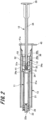
- Fig. 2 is a cross-sectional view illustrating administration parts of the drug-solution administration device of the present embodiment.
- Fig. 3 is an explanatory view illustrating states of a plunger member, a gasket, and a syringe of the present embodiment.
- a drug-solution administration device 1 includes a syringe 11, a plunger member 12, a syringe holder 13 that holds the syringe 11, and a temporary holding portion 51 that temporarily holds the plunger member.
- the syringe 11 is a syringe filled with a drug solution M1 to be described later.
- the syringe 11 has a body portion 21 formed in a substantially cylindrical shape and a discharge portion 22 formed at a distal end portion of the body portion 21.
- a gasket 31 to be described later is slidably inserted into the cylindrical hole 21a of the body portion 21.
- a space of the body portion 21 closer to the discharge portion 22 than the gasket 31 and a space inside the discharge portion 22 form a liquid chamber to be filled with the drug solution M1.
- Examples of the drug solution M1 may include various vaccines to prevent various infectious diseases, such as influenza, but the drug solution is not limited to the vaccine.
- Examples of drug solutions M1 other than the vaccine may include a sugar injection solution like glucose, an injection solution for correction of electrolyte, such as sodium chloride or potassium lactate, vitamins, antibiotic infusion solutions, contrast media, steroids, protease inhibitors, fat emulsions, anticancer agents, anesthetic, heparin calcium, antibody preparations, and the like.
- a flange portion 24 is provided at a proximal end portion of the body portion 21.
- the flange portion 24 protrudes radially outward from an outer peripheral surface of the proximal end portion of the body portion 21.
- the flange portion 24 is engaged with a through-hole 42 provided in the syringe holder 13 to be described later. As a result, the syringe 11 is held by the syringe holder 13.
- an opening 24a communicating with the cylindrical hole 21a of the body portion 21 is formed in the flange portion 24.
- the opening 24a is open in a circular shape.
- the opening 24a is opposed to the gasket 31 to be described later in the state before performing the sterilization treatment as illustrated in Figs. 2 and 3 .
- the gasket 31 and a plunger body 34 which will be described later, are inserted into the opening 24a at the time of use.
- the discharge portion 22 is continuous with one end of the body portion 21 and formed in a substantially cylindrical shape coaxial with the body portion 21.
- the discharge portion 22 is formed in a tapered shape whose diameter continuously decreases toward a distal end opposite to the body portion 21.
- a cylindrical hole 22a of the discharge portion 22 communicates with the cylindrical hole 21a of the body portion 21.
- a luer lock portion 26 which is an example of a screw portion, is joined to the discharge portion 22.
- a needle hub 82 having a suction needle tube 81 configured to suction a drug solution and a needle hub having a needle tube that can pierce a living body are releasably attached to the luer lock portion 26.
- Examples of a material of the syringe 11 may include various types of resin such as polyvinyl chloride, polyethylene, polypropylene, cyclic polyolefin, polystyrene, poly-(4-methylpentene-1), polycarbonate, acrylic resin, an acrylonitrile-butadiene-styrene copolymer, polyester such as polyethylene terephthalate, a butadiene-styrene copolymer, and polyamide (for example, nylon 6, nylon 6/6, nylon 6/10, and nylon 12).
- resin such as polypropylene, cyclic polyolefin, polyester, and poly-(4-methylpentene-1) from the viewpoint that molding is easy.
- the material of the syringe 11 be substantially transparent in order to secure the visibility of the interior.
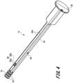
- Fig. 4 is a perspective view illustrating the plunger member 12.
- the plunger member 12 includes the gasket 31, the plunger body 34 that presses the gasket 31, an operation portion 35, a plunger-side engaging portion 36, and a plunger-side retaining portion 38.
- the gasket 31 is formed in a substantially columnar shape.
- One end portion of the gasket 31 is formed in a tapered shape whose diameter continuously decreases toward a distal end.
- This tapered shape corresponds to a shape of an inner surface at the distal end portion of the body portion 21. Therefore, when the gasket 31 is moved toward the distal end portion of the body portion 21, the one end portion of the gasket 31 contacts the inner surface of the distal end portion of the body portion 21 so as not to generate a gap.
- a connecting hole 31a is formed at the other end portion of the gasket 31 as illustrated in Fig. 2 .
- a connecting portion 34a of the plunger body 34 is inserted into the connecting hole 31a so that the gasket 31 and the plunger body 34 are connected.
- two peak portions 32 and 32 are provided on an outer peripheral surface of the gasket 31.
- the two peak portions 32 and 32 are convex portions protruding in a ring shape from the outer peripheral surface of the gasket 31.
- the two peak portions 32 and 32 are provided with a gap therebetween in the axial direction of the gasket 31.
- a material of the gasket 31 is not particularly limited, but it is preferable to use an elastic material in order to obtain favorable liquid tightness with the body portion 21.
- the elastic material may include various rubber materials, such as natural rubber, isobutylene rubber, butyl rubber, and silicone rubber, various thermoplastic elastomers, such as an olefin type and a styrene type, or mixtures thereof.
- the plunger body 34 is formed in a substantially rod shape, and a sectional shape in a direction orthogonal to an axial direction of the plunger body 34 is formed in a substantially cross shape. Further, the plunger body 34 is constituted by four plunger pieces 34b protruding in a direction orthogonal to the axial direction. The four plunger pieces 34b are continuous to be substantially vertical to each other.
- the plunger body 34 is opposed to the opening 24a of the syringe 11 in the state of being held by the temporary holding portion 51 to be described later in the state before performing the sterilization treatment. After performing the sterilization treatment, the plunger body 34 is inserted into the body portion 21 from the opening 24a of the syringe 11 at the time of use, and the most thereof is arranged inside the body portion 21 of the syringe 11 (see Fig. 8 ).
- the connecting portion 34a is provided at the distal end portion of the plunger body 34.
- the connecting portion 34a is inserted into the connecting hole 31a of the gasket 31 and is connected to the gasket 31.
- the gasket 31 is attached to the distal end portion of the plunger body 34.
- the operation portion 35 is provided at a proximal end portion of the plunger body 34.
- the operation portion 35 is formed in a substantially disc shape.
- the gasket 31 arranged at the distal end of the plunger body 34 moves inside the cylindrical hole 21a of the body portion 21 of the syringe 11.
- the plunger-side engaging portion 36 and the plunger-side retaining portion 38 are provided on a shaft portion of the plunger body 34.
- the plunger-side engaging portion 36 is provided on a distal end side in the axial direction of the plunger body 34.
- the plunger-side engaging portion 36 is provided between two plunger pieces 34b and 34b adjacent to each other among the four plunger pieces 34b of the plunger body 34 formed in the cross shape.
- the plunger-side engaging portion 36 is provided at two places symmetric with each other in a direction orthogonal to the axial direction of the plunger body 34 with an axial center of the plunger body 34 interposed between the two places.
- the plunger-side engaging portion 36 has a first engaging portion 36a and a second engaging portion 36b.
- the first engaging portion 36a and the second engaging portion 36b are arranged with a predetermined gap therebetween in the axial direction of the plunger body 34.
- the first engaging portion 36a is arranged to be closer to the distal end side in the axial direction of the plunger body 34 than the second engaging portion 36b.
- the plunger-side retaining portion 38 is provided to be closer to a proximal end side in the axial direction of the plunger body 34 than the plunger-side engaging portion 36.
- the plunger-side retaining portion 38 is formed between two plunger pieces 34b and 34b. which are different from a space between the two plunger pieces 34b and 34b where the plunger-side engaging portion 36 is provided among the four plunger pieces 34b of the plunger body 34.
- the syringe holder 13 has a barrel body portion 41, a through-hole 42, a viewing window 46, a locking hole 47, and a holder collar 48.
- the barrel body portion 41 is formed in a substantially cylindrical shape and covers outer peripheral surfaces of the body portion 21 and the flange portion 24 of the syringe 11 and an outer peripheral surface of the luer lock portion 26.
- the barrel body portion 41 is configured to be grippable by a user.
- a holder opening 41a into which the syringe 11 and the plunger member 12 can be inserted is formed at a proximal end portion of the barrel body portion 41.
- the holder opening 41a is positioned to be closer to the distal end side, which is the proximal end portion of the plunger body 34 inserted into the syringe holder 13, than the operation portion 35. Incidentally, it suffices that the barrel body portion 41 covers at least the outer peripheral surface of the flange portion 24.
- the viewing window 46 is opened at a distal end portion of the barrel body portion 41.
- the viewing window 46 is provided at a position where the liquid chamber formed in the body portion 21 of the syringe 11 is visible from the outside of the syringe holder 13 when the syringe 11 is attached to the syringe holder 13. Accordingly, it is possible to secure the visibility of the interior even if the syringe holder 13 is attached to the syringe 11.
- the holder collar 48 is provided at the proximal end portion of the barrel body portion 41.
- the holder collar 48 protrudes to be substantially vertical from a part of the outer peripheral surface of the barrel body portion 41. Since the holder collar 48 is provided, it is possible to prevent a finger gripping the syringe holder 13 from slipping toward the proximal end direction when the user grips the syringe holder 13 and administers the drug solution. In addition, it is also possible to prevent the drug-solution administration device 1 from rolling when placing the drug-solution administration device 1 on a desk or the like.
- the through-hole 42 and the locking hole 47 are opened in the barrel body portion 41.
- the through-hole 42 and the locking hole 47 are formed to be closer to the proximal end portion side in the axial direction of the barrel body portion 41 than the viewing window 46.
- the flange portion 24 of the syringe 11 is locked by the through-hole 42. As a result, the syringe 11 is held inside the barrel body portion 41.
- the locking hole 47 is formed in the vicinity of the through-hole 42 to be closer to the proximal end portion side in the axial direction of the barrel body portion 41 than the through-hole 42.
- the locking hole 47 is formed to be closer to the proximal end side in the axial direction of the barrel body portion 41 than the flange portion 24 of the syringe 11 held by the barrel body portion 41.
- a locking portion of the temporary holding portion 51 is locked by the locking hole 47.
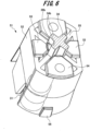
- Fig. 5 is a perspective view illustrating the temporary holding portion 51.
- Fig. 6 is a perspective view illustrating the temporary holding portion 51 and the plunger member 12.
- the temporary holding portion 51 includes a cylindrical body 52, two holding-portion-side engaging portions 53 and 53, two holding-portion-side retaining portions 54 and 54, a plurality of support ribs 55, and a locking portion 56.
- the cylindrical body 52 is formed in a cylindrical shape. One axial end of the cylindrical body 52 is open.
- the two holding-portion-side engaging portions 53 and 53 and two holding-portion-side retaining portions 54 and 54 are provided on the other axial end portion of the cylindrical body 52.
- the two holding-portion-side engaging portions 53 and 53 are arranged at positions opposed to each other at an edge portion of an opening formed at the other end portion of the cylindrical body 52.
- the two holding-portion-side engaging portions 53 and 53 are bent to be substantially vertical from the edge portion of the cylindrical body 52 toward the inside of a cylindrical hole of the cylindrical body 52.
- the holding-portion-side engaging portion 53 is releasably engaged with the plunger-side engaging portion 36 provided on the plunger body 34. That is, the holding-portion-side engaging portion 53 is arranged between the first engaging portion 36a and the second engaging portion 36b of the plunger-side engaging portion 36. Then, the first engaging portion 36a is engaged with the holding-portion-side engaging portion 53 from the distal end side, and the second engaging portion 36b is engaged with the holding-portion-side engaging portion 53 from the proximal end side Match. As a result, the plunger member 12 is temporarily held by the temporary holding portion 51 in a releasable manner.
- the two holding-portion-side retaining portions 54 and 54 illustrating one example of a retaining portion are formed at the edge portion of the opening formed at the other end portion of the cylindrical body 52 between the two holding-portion-side engaging portions 53 and 53.
- the two holding-portion-side retaining portions 54 and 54 are arranged at positions opposed to each other.
- the two holding-portion-side retaining portions 54 and 54 are bent to be substantially vertical from the edge portion of the cylindrical body 52 toward the inside of the cylindrical hole of the cylindrical body 52. Then, insertion holes through which the plunger body 34 is inserted are formed by distal end portions of the two holding-portion-side engaging portions 53 and 53 and the two holding-portion-side retaining portions 54 and 54.
- the present invention is not limited thereto, and the retaining portion and the temporary holding portion 51 may be formed using different members.
- the plurality of support ribs 55 (four in the present embodiment) illustrating one example of a support portion are formed between the holding-portion-side engaging portion 53 and the holding-portion-side retaining portion 54.
- the plurality of support ribs 55 protrude from an inner wall of the cylindrical body 52 toward the inside of the cylindrical hole with a predetermined length.
- the plurality of support ribs 55 extend from the other end portion of the cylindrical body 52 to a midway portion in the axial direction.
- the plunger body 34 when the plunger body 34 is inserted into the temporary holding portion 51, the plurality of support ribs 55 contacts the plunger piece 34b of the plunger body 34. Therefore, the plunger body 34 is held by the plurality of support ribs 55. Thereby, the plunger member 12 can be held by the temporary holding portion 51 without rattling.
- the gasket 31 is covered by the cylindrical body 52 of the temporary holding portion 51 in the state before performing sterilization treatment as illustrated in Figs. 3 and 6 . As a result, it is possible to prevent the user's finger from contacting the gasket 31, and it is possible to prevent the gasket 31 that has been subjected to the sterilization treatment from being contaminated.
- the locking portion 56 is provided at the distal end portion on an outer peripheral surface of the cylindrical body 52 as illustrated in Fig. 5 .
- the locking portion 56 protrudes outward from the outer peripheral surface of the cylindrical body 52.
- the locking portion 56 is locked by the locking hole 47 of the syringe holder 13 when the cylindrical body 52 is inserted into the cylindrical hole of the barrel body portion 41 of the syringe holder 13.
- the temporary holding portion 51 is opposed to the flange portion 24 of the syringe 11 as illustrated in Figs. 2 and 3 . Further, the plunger member 12 is temporarily held by the temporary holding portion 51 in a state where the gasket 31 is opposed to the opening 24a of the syringe 11 with a gap between the gasket 31 and the opening 24a.
- Fig. 7 is a perspective view illustrating the drug-solution administration device 1 at the time of sucking the drug solution
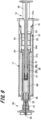
- Fig. 8 is a cross-sectional view illustrating the drug-solution administration device 1 after the sterilization treatment.
- Fig. 9 is a cross-sectional view illustrating a state after sucking the drug solution
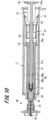
- Fig. 10 is a cross-sectional view illustrating a state after administering the drug solution.
- the syringe 11 is attached to the syringe holder 13 as illustrated in Figs. 1 and 2 .
- the plunger body 34 is inserted in the insertion hole formed at the distal end portions of the two holding-portion-side engaging portions 53 and 53 and the two holding-portion-side retaining portions 54 and 54 in the temporary holding portion 51 as illustrated in Fig. 6 .
- the plunger-side engaging portion 36 is engaged with the holding-portion-side engaging portion 53 of the temporary holding portion 51.
- the gasket 31 is connected to the connecting portion 34a (see Fig. 2 ) of the plunger body 34.
- the gasket 31 is covered by the cylindrical body 52 of the temporary holding portion 51, and the plunger member 12 is temporarily held by the temporary holding portion 51.
- the temporary holding portion 51 and the plunger member 12 are inserted into the cylindrical hole of the barrel body portion 41 of the syringe holder 13. Then, the locking portion 56 of the temporary holding portion 51 is locked by the locking hole 47 of the syringe holder 13 as illustrated in Figs. 1 and 3 . As a result, the plunger member 12 is temporarily held by the temporary holding portion 51 in a state where the gasket 31 is opposed to the opening 24a of the syringe 11.
- the sterilization treatment is performed using high-temperature steam or gases such as high-pressure steam sterilization (autoclave) and ethylene oxide gas (EOG) sterilization.
- the gasket 31 is not inserted into the cylindrical hole 21a of the syringe 11, and is arranged outside the syringe 11.
- a space between the two peak portions 32 of the gasket 31 is opened.
- a plurality of gaps is formed in the cylindrical body 52 of the temporary holding portion 51 at the distal end portion in the axial direction, between the holding-portion-side engaging portion 53 and the support rib 55, between the support rib 55 and the holding-portion-side retaining portion 54, and the like.
- the drug-solution administration device 1 may be wrapped in a state where the gasket 31 is opposed to the opening 24a of the syringe 11, or the drug-solution administration device 1 may be wrapped after inserting the gasket 31 into the cylindrical hole 21a of the syringe 11 to be described later.
- the plunger member 12 is operated to insert the gasket 31 into the cylindrical hole 21a of the syringe 11 at the time of wrapping the drug-solution administration device 1 or at the time of using the drug-solution administration device 1 as illustrated in Figs. 7 and 8 .
- FIG. 7 illustrates an example in which an injection needle assembly 80 having a suction needle tube 81 configured to suck a drug solution from a vial containing the drug solution is attached to the syringe 11 in order to fill the liquid chamber of the syringe 11 with the drug solution.
- the needle hub 82 of the injection needle assembly 80 is screwed into the luer lock portion 26 of the syringe 11.
- the cylindrical hole 21a of the syringe 11 and the suction needle tube 81 of the injection needle assembly 80 communicate with each other via the discharge portion 22.
- the injection needle assembly 80 illustrated in Fig. 7 may be attached to the syringe 11 after inserting the gasket 31 into the cylindrical hole 21a of the syringe 11 as illustrated in Fig. 8 .
- the gasket 31 may be inserted into the cylindrical hole 21a of the syringe 11 after the injection needle assembly 80 illustrated in Fig. 7 is attached to the syringe 11.
- the plunger-side retaining portion 38 climbs over the holding-portion-side retaining portion 54 to move toward the distal end side of the holding-portion-side retaining portion 54. Then, the plunger-side retaining portion 38 can abut on the holding-portion-side retaining portion 54 from the distal end portion side. As a result, it is possible to prevent the plunger member 12 from falling out of the temporary holding portion 51 that has been attached to the syringe holder 13. At this time, a distal end surface of the gasket 31 is spaced apart from the distal end surface of the cylindrical hole 22a of the body portion 21.
- the suction needle tube 81 of the injection needle assembly 80 pierces through the vial, and the plunger member 12 is pulled toward the proximal end of the syringe 11.
- the drug solution M1 is sucked through the suction needle tube 81 of the injection needle assembly 80 so that the liquid chamber of the syringe 11 is filled with the drug solution M1.
- the injection needle assembly 80 is removed from the luer lock portion 26.
- the injection needle assembly 90 having an administration needle tube 91 for piercing the living body is attached to the syringe 11 as illustrated in Fig. 9 . That is, the needle hub 92 of the injection needle assembly 90 is screwed into the luer lock portion 26 of the syringe 11 as illustrated in Fig. 9 . As a result, the administration needle tube 91 of the injection needle assembly 90 communicates with the cylindrical hole 21a of the syringe 11 via the discharge portion 22.
- the administration needle tube 91 pierces through the user's skin.
- the gasket 31 is slidably moved toward the distal end portion of the syringe 11 by operating the plunger member 12.
- the drug solution M1 filling the liquid chamber of the syringe 11 is pushed out of the administration needle tube 91 by the gasket 31.
- the administration of the drug solution to the living body using the drug-solution administration device 1 is completed.
- the embodiment of the present invention has been described including the operational effects thereof.
- the drug-solution administration device of the present invention is not limited to the above-described embodiment, and various modifications can be made within a scope not departing from the invention described in the claims.
- various other administration parts such as a needle-free syringe having no needle tube and an intranasal administration device for administering a drug solution to a nasal cavity or the like can be applied as an administration part to be attached to the drug-solution administration device 1 as long as the part is attached by screwing.
- a male screw portion may be provided in the discharge portion 22 to be screwed with a female screw portion provided in the administrate part.
- the temporary holding portion 51 and the syringe holder 13 may be integrally molded, or the syringe holder 13 is not necessarily provided.
- the temporary holding portion may be releasably attached to the flange portion or the like of the syringe, or the temporary holding portion may be fixed to the syringe by adhesion or welding.
- the temporary holding portion and the syringe may be integrally molded.
- the gasket 31 is covered by the cylindrical body 52 of the temporary holding portion 51 until the insertion of the gasket 31 into the syringe 11 after the sterilization treatment.
- the syringe holder 13 is not provided, it is possible to prevent the finger of the user from contacting the gasket 31.
- the plunger body of the plunger member and the cylinder body of the temporary holding portion may be fixed by ultrasonic welding or laser welding so as to temporarily hold the plunger member by the temporary holding portion.
- a fixing strength between the plunger body and the cylindrical body is set to a strength at which the plunger body and the cylindrical body are broken when the plunger member is pressed after the sterilization treatment.
- the temporary holding portion and the plunger member may be integrally molded by providing a thin portion which is broken when the plunger member is pressed.
Landscapes
- Health & Medical Sciences (AREA)
- Vascular Medicine (AREA)
- Engineering & Computer Science (AREA)
- Anesthesiology (AREA)
- Biomedical Technology (AREA)
- Heart & Thoracic Surgery (AREA)
- Hematology (AREA)
- Life Sciences & Earth Sciences (AREA)
- Animal Behavior & Ethology (AREA)
- General Health & Medical Sciences (AREA)
- Public Health (AREA)
- Veterinary Medicine (AREA)
- Infusion, Injection, And Reservoir Apparatuses (AREA)
Claims (8)
- Vorrichtung (1) zur Verabreichung einer Arzneimittellösung, umfassend:eine Spritze (11), die einen zylindrischen Körperabschnitt (21), der so konfiguriert ist, dass er darin mit einer Arzneimittellösung gefüllt werden kann, einen Auslassabschnitt (22), der an einem distalen Endabschnitt des Körperabschnitts (21) ausgebildet ist, und eine Öffnung (24a), die an einem proximalen Endabschnitt des Körperabschnitts (21) ausgebildet ist, umfasst;eine Dichtung (31), die im Inneren eines zylindrischen Loches (21a) des Körperabschnitts (21) verschiebbar ist;ein Kolbenelement (12), das einen Kolbenkörper (34) umfasst, an dem die Dichtung (31) angebracht ist;einen Spritzenhalterung (13) zum Halten der Spritze (11); undeinen vorübergehenden Halteabschnitt (51), der in der Spritzenhalterung (13) vorgesehen ist,dadurch gekennzeichnet, dassder vorübergehende Halteabschnitt (51) einen Verriegelungsabschnitt (56) umfasst, der so konfiguriert ist, dass er durch ein Verriegelungsloch (47) der Spritzenhalterung (13) verriegelt wird;ein auf der Seite des Halteabschnitts liegender Eingriffsabschnitt (53), der lösbar mit einem auf der Seite des Kolbens liegenden Eingriffsabschnitt (36) des Kolbenkörpers (34) derart in Eingriff steht, dass das Kolbenelement (12) lösbar durch den vorübergehenden Halteabschnitt (51) durch den Eingriff zwischen dem auf der Seite des Kolbens liegenden Eingriffsabschnitt (36) und dem auf der Seite des Halteabschnitts liegenden Eingriffsabschnitt (53) in einem Zustand lösbar gehalten wird, in welchem die Öffnung (24a) des Körperabschnitts (21) und eine distale Endfläche der Dichtung (31) einander mit einem Spalt dort dazwischen gegenüberliegen.
- Vorrichtung (1) zur Verabreichung einer Arzneimittellösung nach Anspruch 1, wobei eine Injektionsnadel-Anordnung (90), die ein Nadelrohr umfasst, das eine Nadelspitze aufweist, die so konfiguriert ist, dass sie in einen lebenden Körper einsticht, oder eine andere Injektionsnadel-Anordnung (80), die ein Saugnadelrohr (81) umfasst, das eine Nadelspitze aufweist, die so konfiguriert ist, dass sie die Arzneimittellösung ansaugt, abnehmbar an dem Auslassabschnitt (22) der Spritze (11) angebracht sind.
- Vorrichtung (1) zur Verabreichung einer Arzneimittellösung nach Anspruch 1 oder 2, wobei das Halten des Kolbenelements (12) durch den vorübergehenden Halteabschnitt (51) lösbar ist, wenn das Kolbenelement (12) in Richtung eines distalen Endes der Spritze (11) gedrückt wird.
- Vorrichtung (1) zur Verabreichung einer Arzneimittellösung nach Anspruch 1, wobei der auf der Seite des Kolbens liegende Eingriffsabschnitt (36) einen ersten Eingriffsabschnitt (36a), der von einer distalen Endseite her mit dem auf der Seite des Halteabschnitts liegenden Eingriffsabschnitt (53) in Eingriff steht, und einen zweiten Eingriffsabschnitt (36b) umfasst, der von einer proximalen Endseite her mit dem auf der Seite des Halteabschnitts liegenden Eingriffsabschnitt (53) in Eingriff steht, und wobei das Kolbenelement (12) durch den vorübergehenden Halteabschnitt (51) lösbar gehalten wird, wenn der auf der Seite des Halteabschnitts liegende Eingriffsabschnitt (53) zwischen dem ersten Eingriffsabschnitt (36a) und dem zweiten Eingriffsabschnitt (36b) positioniert ist.
- Vorrichtung (1) zur Verabreichung einer Arzneimittellösung nach Anspruch 4, wobei die auf der Seite des Kolbens liegenden Eingriffsabschnitte (36a, 36b) an zwei Stellen vorgesehen sind, die so positioniert sind, dass sie einander gegenüberliegen, wobei eine axiale Mitte des Kolbenkörpers (34) dazwischen angeordnet ist, und wobei der auf der Seite des Halteabschnitts liegende Eingriffsabschnitt (53) an zwei Stellen vorgesehen ist, die so positioniert sind, dass sie einander gegenüberliegen, wobei eine axiale Mitte des Körperabschnitts (21) dazwischen angeordnet ist.
- Vorrichtung (1) zur Verabreichung einer Arzneimittellösung nach einem der Ansprüche 4 bis 5, wobei der Kolbenkörper (34) einen auf der Seite des Kolbens liegenden Rückhalteabschnitt (38) aufweist, der an einer Position proximal des auf der Seite des Kolbens liegenden Eingriffsabschnitts (36) vorgesehen ist und sich von dem auf der Seite des Kolbens liegenden Eingriffsabschnitt (36) rund um die axiale Mitte des Kolbenkörpers (34) unterscheidet, wobei die Vorrichtung (1) zur Verabreichung einer Arzneimittellösung ferner einen Rückhalteabschnitt umfasst, der an einer Position vorgesehen ist, die sich von dem auf der Seite des Halteabschnitts liegenden Eingriffsabschnitt (53) rund um die axiale Mitte des Körperabschnitts (21) unterscheidet, und der so konfiguriert ist, dass er an einem auf der Seite des Kolbens liegenden Rückhalteabschnitt (38) von einer proximalen Endseite anliegt, wobei der auf der Seite des Kolbens liegende Rückhalteabschnitt (38) und ein Rückhalteabschnitt (54) so konfiguriert sind, dass sie eine Bewegung des Kolbenkörpers (34) in Richtung der proximalen Endseite einschränken, wenn der auf der Seite des Kolbens liegende Rückhalteabschnitt (38) über den Rückhalteabschnitt (54) von der proximalen Endseite klettert und der auf der Seite des Kolbens liegende Rückhalteabschnitt (38) und der Rückhalteabschnitt (54) aneinander anliegen, und wobei die distale Endfläche der Dichtung (31) von einer distalen Endfläche des zylindrischen Loches (21a, 22a) in dem Körperabschnitt (21) beabstandet ist, wenn der auf der Seite des Kolbens liegende Rückhalteabschnitt (38) und der Rückhalteabschnitt (54) aneinander anliegen.
- Vorrichtung zur Verabreichung einer Arzneimittellösung nach einem der Ansprüche 1 bis 6, wobei der vorübergehende Halteabschnitt (51) einen Stützabschnitt (55) umfasst, der den Kolbenkörper (34) stützt, und wobei eine Neigung einer Achse des Kolbenkörpers (34) in Bezug auf eine Achse des Körperabschnitts (21) durch den Stützabschnitt begrenzt ist.
- Verfahren zur Herstellung einer Vorrichtung (1) zur Verabreichung einer Arzneimittellösung nach einem der Ansprüche 1 bis 7,
wobei das Verfahren umfasst:einen Schritt des Anbringens der Spritze (11) an der Spritzenhalterung (13),einen Schritt des Eingreifens des auf der Seite des Kolbens liegenden Eingriffsabschnitts (36) mit dem auf der Seite des Halterungsabschnitts liegenden Eingriffsabschnitt (53) des temporären Halteabschnitts (51),einen Schritt des Anbringens der Dichtung (31) an dem Kolbenkörper (34) des Kolbenelements (12),einen Schritt des Einsetzens des temporären Halteabschnitts (51) und des Kolbenelements (12) in ein zylindrisches Loch eines Zylinderkörperabschnitts (41) der Spritzenhalterung (1),einen Schritt des Verriegelns des Verriegelungsabschnitts (56) des temporären Halteabschnitts (51) durch das Verriegelungsloch (47) der Spritzenhalterung (13),einen Schritt des Haltens des Kolbenelements (12) durch den temporären Halteabschnitt (51) in einem Zustand, in dem die Öffnung (24a), die in dem proximalen Endabschnitt des Körperabschnitts (21) der Spritze (11) ausgebildet ist, und die distale Endfläche der Dichtung (31) einander mit dem dazwischen liegenden Spalt gegenüberliegen;
undeinen Schritt des Sterilisierens der Spritze (11), der Dichtung (31), des Kolbenelements (12) und des temporären Halteabschnitts (51) mit einem Sterilisationsgas oder Hochdruckdampf in einem Zustand, in dem das Kolbenelement (12) durch den temporären Halteabschnitt (51) gehalten wird.
Applications Claiming Priority (2)
| Application Number | Priority Date | Filing Date | Title |
|---|---|---|---|
| JP2016066145 | 2016-03-29 | ||
| PCT/JP2017/012795 WO2017170635A1 (ja) | 2016-03-29 | 2017-03-29 | 薬液投与器具、薬液投与器具の使用方法及び薬液投与器具の製造方法 |
Publications (3)
| Publication Number | Publication Date |
|---|---|
| EP3437681A1 EP3437681A1 (de) | 2019-02-06 |
| EP3437681A4 EP3437681A4 (de) | 2019-09-04 |
| EP3437681B1 true EP3437681B1 (de) | 2024-04-03 |
Family
ID=59965803
Family Applications (1)
| Application Number | Title | Priority Date | Filing Date |
|---|---|---|---|
| EP17775172.4A Active EP3437681B1 (de) | 2016-03-29 | 2017-03-29 | Vorrichtung zur verabreichung von medikamenten, verfahren zur verabreichung von medikamenten und verfahren zur herstellung einer vorrichtung zur verabreichung von medikamenten |
Country Status (3)
| Country | Link |
|---|---|
| EP (1) | EP3437681B1 (de) |
| JP (1) | JP6914913B2 (de) |
| WO (1) | WO2017170635A1 (de) |
Families Citing this family (3)
| Publication number | Priority date | Publication date | Assignee | Title |
|---|---|---|---|---|
| KR102368459B1 (ko) * | 2017-10-18 | 2022-02-25 | 마에다 인더스트리 가부시키가이샤 | 주사기의 개스킷 빠짐 방지 기구 |
| TWI712431B (zh) * | 2018-03-19 | 2020-12-11 | 日商前田產業股份有限公司 | 注射器之墊片脫落防止機構 |
| AU2019262000B2 (en) * | 2018-05-01 | 2024-02-08 | Csp Technologies, Inc. | Medicament delivery device and method of using and making same |
Family Cites Families (6)
| Publication number | Priority date | Publication date | Assignee | Title |
|---|---|---|---|---|
| SE9101261D0 (sv) * | 1991-04-25 | 1991-04-25 | Kabi Pharmacia Ab | Injection container |
| US5785682A (en) * | 1995-03-22 | 1998-07-28 | Abbott Laboratories | Pre-filled syringe drug delivery system |
| JP4152104B2 (ja) * | 2001-12-28 | 2008-09-17 | テルモ株式会社 | シリンジおよびガスケット |
| JP2004313369A (ja) * | 2003-04-15 | 2004-11-11 | Menicon Co Ltd | カートリッジ注入器、カートリッジ及び該注入器を備えた眼科用注入器セット |
| SE529693C2 (sv) * | 2005-03-04 | 2007-10-30 | Millipore Ab | Steril spruta |
| JP6411097B2 (ja) * | 2014-07-03 | 2018-10-24 | テルモ株式会社 | プレフィルドシリンジ |
-
2017
- 2017-03-29 WO PCT/JP2017/012795 patent/WO2017170635A1/ja active Application Filing
- 2017-03-29 EP EP17775172.4A patent/EP3437681B1/de active Active
- 2017-03-29 JP JP2018508122A patent/JP6914913B2/ja active Active
Also Published As
| Publication number | Publication date |
|---|---|
| WO2017170635A1 (ja) | 2017-10-05 |
| JP6914913B2 (ja) | 2021-08-04 |
| JPWO2017170635A1 (ja) | 2019-02-07 |
| EP3437681A1 (de) | 2019-02-06 |
| EP3437681A4 (de) | 2019-09-04 |
Similar Documents
| Publication | Publication Date | Title |
|---|---|---|
| JP5746127B2 (ja) | 注入ポートを通って治療剤を送出するための方法および装置 | |
| EP0239673B1 (de) | Spritzenbehälter und hypodermatische Nadel | |
| AU2016237183B2 (en) | Syringe holder and medical solution administration set | |
| US5718690A (en) | Hypodermic injector system and method for maintaining the sterility thereof prior to use | |
| EP3042679B1 (de) | Aussenrohr für spritze und fertigspritze | |
| EP3437681B1 (de) | Vorrichtung zur verabreichung von medikamenten, verfahren zur verabreichung von medikamenten und verfahren zur herstellung einer vorrichtung zur verabreichung von medikamenten | |
| WO2012039276A1 (ja) | 薬剤注射装置の組立方法 | |
| RU2647441C2 (ru) | Узел, содержащий переходник для сопряжения с медицинским контейнером и блистерную упаковку | |
| EP3127570B1 (de) | Spritze | |
| WO2011122393A1 (ja) | プレフィルドシリンジ | |
| US9757526B2 (en) | Drug administration instrument | |
| WO2011068131A1 (ja) | プレフィルドシリンジ | |
| JP5411729B2 (ja) | 薬剤投与具 | |
| JPWO2012043161A1 (ja) | 針付医療器具 | |
| CN111670059B (zh) | 预填充式注射器和对预填充式注射器进行灭菌的方法 | |
| JP2011115345A (ja) | プレフィルドシリンジ | |
| JP2011212183A (ja) | プレフィルドシリンジ | |
| JPH10272181A (ja) | シリンジおよびシリンジ組立体 | |
| JP2000042106A (ja) | 薬液混合用注射器 | |
| WO2014061151A1 (ja) | 薬剤投与器具 | |
| WO2014033865A1 (ja) | 薬剤投与器具 | |
| JP2002078801A (ja) | 液体注入器具 |
Legal Events
| Date | Code | Title | Description |
|---|---|---|---|
| STAA | Information on the status of an ep patent application or granted ep patent |
Free format text: STATUS: THE INTERNATIONAL PUBLICATION HAS BEEN MADE |
|
| PUAI | Public reference made under article 153(3) epc to a published international application that has entered the european phase |
Free format text: ORIGINAL CODE: 0009012 |
|
| STAA | Information on the status of an ep patent application or granted ep patent |
Free format text: STATUS: REQUEST FOR EXAMINATION WAS MADE |
|
| 17P | Request for examination filed |
Effective date: 20181023 |
|
| AK | Designated contracting states |
Kind code of ref document: A1 Designated state(s): AL AT BE BG CH CY CZ DE DK EE ES FI FR GB GR HR HU IE IS IT LI LT LU LV MC MK MT NL NO PL PT RO RS SE SI SK SM TR |
|
| AX | Request for extension of the european patent |
Extension state: BA ME |
|
| DAV | Request for validation of the european patent (deleted) | ||
| DAX | Request for extension of the european patent (deleted) | ||
| A4 | Supplementary search report drawn up and despatched |
Effective date: 20190807 |
|
| RIC1 | Information provided on ipc code assigned before grant |
Ipc: A61M 5/00 20060101ALI20190801BHEP Ipc: A61M 5/31 20060101ALI20190801BHEP Ipc: A61M 5/315 20060101AFI20190801BHEP |
|
| STAA | Information on the status of an ep patent application or granted ep patent |
Free format text: STATUS: EXAMINATION IS IN PROGRESS |
|
| 17Q | First examination report despatched |
Effective date: 20200818 |
|
| STAA | Information on the status of an ep patent application or granted ep patent |
Free format text: STATUS: EXAMINATION IS IN PROGRESS |
|
| STAA | Information on the status of an ep patent application or granted ep patent |
Free format text: STATUS: EXAMINATION IS IN PROGRESS |
|
| GRAP | Despatch of communication of intention to grant a patent |
Free format text: ORIGINAL CODE: EPIDOSNIGR1 |
|
| STAA | Information on the status of an ep patent application or granted ep patent |
Free format text: STATUS: GRANT OF PATENT IS INTENDED |
|
| INTG | Intention to grant announced |
Effective date: 20231026 |
|
| GRAS | Grant fee paid |
Free format text: ORIGINAL CODE: EPIDOSNIGR3 |
|
| GRAA | (expected) grant |
Free format text: ORIGINAL CODE: 0009210 |
|
| STAA | Information on the status of an ep patent application or granted ep patent |
Free format text: STATUS: THE PATENT HAS BEEN GRANTED |
|
| AK | Designated contracting states |
Kind code of ref document: B1 Designated state(s): AL AT BE BG CH CY CZ DE DK EE ES FI FR GB GR HR HU IE IS IT LI LT LU LV MC MK MT NL NO PL PT RO RS SE SI SK SM TR |
|
| REG | Reference to a national code |
Ref country code: GB Ref legal event code: FG4D |
|
| REG | Reference to a national code |
Ref country code: CH Ref legal event code: EP |
|
| REG | Reference to a national code |
Ref country code: IE Ref legal event code: FG4D |
|
| REG | Reference to a national code |
Ref country code: DE Ref legal event code: R096 Ref document number: 602017080626 Country of ref document: DE |