EP3436740B1 - Eine wash light leuchte mit spezialeffekten - Google Patents
Eine wash light leuchte mit spezialeffekten Download PDFInfo
- Publication number
- EP3436740B1 EP3436740B1 EP17733564.3A EP17733564A EP3436740B1 EP 3436740 B1 EP3436740 B1 EP 3436740B1 EP 17733564 A EP17733564 A EP 17733564A EP 3436740 B1 EP3436740 B1 EP 3436740B1
- Authority
- EP
- European Patent Office
- Prior art keywords
- light
- lens
- light guide
- light engine
- engine module
- Prior art date
- Legal status (The legal status is an assumption and is not a legal conclusion. Google has not performed a legal analysis and makes no representation as to the accuracy of the status listed.)
- Active
Links
Images


Classifications
-
- F—MECHANICAL ENGINEERING; LIGHTING; HEATING; WEAPONS; BLASTING
- F21—LIGHTING
- F21V—FUNCTIONAL FEATURES OR DETAILS OF LIGHTING DEVICES OR SYSTEMS THEREOF; STRUCTURAL COMBINATIONS OF LIGHTING DEVICES WITH OTHER ARTICLES, NOT OTHERWISE PROVIDED FOR
- F21V14/00—Controlling the distribution of the light emitted by adjustment of elements
- F21V14/06—Controlling the distribution of the light emitted by adjustment of elements by movement of refractors
-
- F—MECHANICAL ENGINEERING; LIGHTING; HEATING; WEAPONS; BLASTING
- F21—LIGHTING
- F21S—NON-PORTABLE LIGHTING DEVICES; SYSTEMS THEREOF; VEHICLE LIGHTING DEVICES SPECIALLY ADAPTED FOR VEHICLE EXTERIORS
- F21S10/00—Lighting devices or systems producing a varying lighting effect
- F21S10/005—Lighting devices or systems producing a varying lighting effect using light guides
-
- F—MECHANICAL ENGINEERING; LIGHTING; HEATING; WEAPONS; BLASTING
- F21—LIGHTING
- F21V—FUNCTIONAL FEATURES OR DETAILS OF LIGHTING DEVICES OR SYSTEMS THEREOF; STRUCTURAL COMBINATIONS OF LIGHTING DEVICES WITH OTHER ARTICLES, NOT OTHERWISE PROVIDED FOR
- F21V13/00—Producing particular characteristics or distribution of the light emitted by means of a combination of elements specified in two or more of main groups F21V1/00 - F21V11/00
- F21V13/02—Combinations of only two kinds of elements
-
- F—MECHANICAL ENGINEERING; LIGHTING; HEATING; WEAPONS; BLASTING
- F21—LIGHTING
- F21V—FUNCTIONAL FEATURES OR DETAILS OF LIGHTING DEVICES OR SYSTEMS THEREOF; STRUCTURAL COMBINATIONS OF LIGHTING DEVICES WITH OTHER ARTICLES, NOT OTHERWISE PROVIDED FOR
- F21V7/00—Reflectors for light sources
- F21V7/0091—Reflectors for light sources using total internal reflection
-
- F—MECHANICAL ENGINEERING; LIGHTING; HEATING; WEAPONS; BLASTING
- F21—LIGHTING
- F21W—INDEXING SCHEME ASSOCIATED WITH SUBCLASSES F21K, F21L, F21S and F21V, RELATING TO USES OR APPLICATIONS OF LIGHTING DEVICES OR SYSTEMS
- F21W2131/00—Use or application of lighting devices or systems not provided for in codes F21W2102/00-F21W2121/00
- F21W2131/40—Lighting for industrial, commercial, recreational or military use
- F21W2131/406—Lighting for industrial, commercial, recreational or military use for theatres, stages or film studios
-
- F—MECHANICAL ENGINEERING; LIGHTING; HEATING; WEAPONS; BLASTING
- F21—LIGHTING
- F21Y—INDEXING SCHEME ASSOCIATED WITH SUBCLASSES F21K, F21L, F21S and F21V, RELATING TO THE FORM OR THE KIND OF THE LIGHT SOURCES OR OF THE COLOUR OF THE LIGHT EMITTED
- F21Y2115/00—Light-generating elements of semiconductor light sources
- F21Y2115/10—Light-emitting diodes [LED]
Definitions
- the present disclosure generally relates to a method for providing a wash light luminaire, specifically to optical systems and a method relating to providing single and multiple beams from a wash light luminaire.
- Luminaires with automated and remotely controllable functionality are well known in the entertainment and architectural lighting markets. Such products are commonly used in theatres, television studios, concerts, theme parks, night clubs, and other venues. A typical product will provide control over the functions of the luminaire allowing the operator to control the intensity and color of the light beam from the luminaire that is shining on the stage or in the studio. Many products also provide control over other parameters such as the position, focus, beam size, beam shape, and beam pattern. In such products that contain light emitting diodes (LEDs) to produce the light output it is common to use more than one color of LEDs and to be able to adjust the intensity of each color separately such that the output, which comprises the combined mixed output of all LEDs, can be adjusted in color. For example, such a product may use red, green, blue, and white LEDs with separate intensity controls for each of the four types of LEDs. This allows the user to mix almost limitless combinations and to produce nearly any color they desire.
- LEDs light emitting diodes
- FIG. 1 illustrates a typical multiparameter automated luminaire system 10.
- These systems typically include a plurality of multi parameter automated luminaires 12 which typically each contain on-board a light source (not shown), light modulation devices, electric motors coupled to mechanical drive systems, and control electronics (not shown).
- each automated luminaire 12 is connected in series or in parallel to data link 14 to one or more control desks 15.
- the luminaire system 10 is typically controlled by an operator through the control desk 15.
- Luminaires have been provided using non-LED light sources designed to produce a single narrow beam or a plurality of such beams. Such luminaires may use low etendue, High Intensity Discharge (HID) light sources with a small arc gap in order to facilitate the production of tight, almost parallel light beams.
- HID High Intensity Discharge
- U.S. Patent Application Nos. 14/042,758 and 14/042,759 provide examples of such a system.
- Single and multi-color LED sourced luminaires have also been produced with narrow beam capability using sophisticated collimation systems as, for example, disclosed in U.S. Patent Application No. 14/405,355 . LEDs however are high etendue light sources by comparison with HID and it is difficult to produce multiple beam systems using LED light sources.
- Prior art optical systems utilizing multiple LED emitters may be unforgiving when it is desired to produce a homogeneous image with a light output capable of being blended between units to provide seamless coverage. This mode of operation is often called a wash light as it washes the stage with light.
- Prior art systems will commonly utilize multiple LED light sources and attempt to blend them into a homogeneous whole. This approach is often unsuccessful because the individual differently colored LED emitters are still visible producing a multi-colored effect when viewing the light rather than the desired appearance of a single color.
- Other prior art systems use a secondary lens but that has the drawback that the output lens may not then be filled completely and all the light will appear to be emitted from a portion at the centre of the output lens. This reduces the performance of the luminaire as a wash light as it is an important feature of wash luminaires that the effective light source be as large as possible in order to soften and reduce shadowing.
- EP2177816 , WO2014031641 , WO 2010/113100 , WO 2015/022644 , and EP 1 550 908 which have been cited as relating to the state of the art of the present invention.
- the present disclosure generally relates to a method for providing special effects in wash light luminaires, specifically to a method relating to providing controllable lighting effects from a luminaire with a wash light distribution with a large effective source and true blending output distribution.
- Light emitting module 20 comprises a single LED or an array of LEDs, which may include a primary optic (not shown).
- Light emitting module 20 may contain a single color of LEDs or may contain multiple dies, each of which may be of common or differing colors.
- light emitting module 20 may comprise one each of a Red, Green, Blue and White LED.
- light emitting module 20 may comprise a single LED chip or package while in yet further embodiments light emitting module 20 may comprise multiple LED chips or packages either under a single primary optic or each package with its own primary optic.
- these LED die(s) may be paired with optical lens element(s) as part of the LED light-emitting module.
- light emitting module 20 may comprise more than four colors of LEDs. For example, seven colors may be used, one each of a Red, Green, Blue, White, Amber, Cyan, and Deep Blue/UV LED die.
- Light guide optic 22 may be a device utilizing internal reflection so as to collect, homogenize and constrain and conduct the light to exit port 23.
- Light guide optic 22 may be a hollow tube with a reflective inner surface such that light impinging into the entry port may be reflected multiple times along the tube before leaving at the exit port 23.
- Light guide optic 22 may be a square tube, a hexagonal tube, a heptagonal tube, an octagonal tube, a circular tube, or a tube of any other cross section.
- light guide optic 22 may be a solid rod constructed of glass, transparent plastic, or other optically transparent material where the reflection of the incident light beam within the rod is due to "total internal reflection" (TIR) from the interface between the material of the rod and the surrounding air.
- the integrating rod may be a square rod, a hexagonal rod, a heptagonal rod, an octagonal rod, a circular rod, or a rod of any other cross section.
- Light guide optic 22, whether solid or hollow, and with any number of sides, may have entry port 21 and exit port 23 that differ in cross sectional shape. For example, a square entry port 21 and an octagonal exit port 23.
- light guide optic 22 may have sides which are tapered so that the entrance aperture is smaller than the exit aperture.
- the advantage of such a structure is that the divergence angle of light exiting the light guide optic 22 at exit port 23 will be smaller than the divergence angle for light entering the light guide optic 22.
- the combination of a smaller divergence angle from a larger aperture serves to conserve the etendue of the system.
- a tapered light guide optic 22 may provide similar functionality to a condensing optical system.
- light guide optic 22 has both a square entry port 21 and a square exit port 23. For the desired flower reminiscent effect, it is advantageous to use shapes with opposing sides and to have the same shape cross section along the length of the light guide optic 22.
- Light guide optic 22 may have an aspect ratio where its length is much greater than its diameter. The greater the ratio between length and diameter, the better the resultant mixing and homogenization will be.
- Light guide optic 22 may be enclosed in a tube or protective sleeve 24 that provides mechanical protection against damage, scratches, and dust.
- light guide optic 22 is of such a length so as to collimate and direct but deliberately provide incomplete homogenization of the light coming from individual LEDs on light emitting module 20. This incomplete homogenization may be advantageously utilized in the remainder of the optical system.
- the exit port of light guide 22 is polished, rather than being diffused or textured, to maintain the incomplete homogenization of the input light beams. In one embodiment the beams are less than 50% homogenized such that individual beams or colors from separate LEDs are still clearly visible.
- Light guide optic 22 within its protective sleeve 24 is mounted such that it may be freely rotated along its long, optical, axis through gear 32 and motor (not shown) supported by bearing 66. Rotating light guide 22 will cause the emitted light beams from exit port 23 to also rotate around the optical axis of the system. In fact, the light beam movement and rotation will be complex, as a function of the rotation of the input port of light guide optic 22 across the array of LEDs in fixed light emitting module 20 and the total internal reflection within the rotating light guide. Thus, the light beams exiting the light guide optic 22 will present a complex and dynamic pattern of moving beams. Light guide optic 22 may be rotated in either direction and at any speed under control of the operator.
- the light from the exit port 23 of light guide optic 22 will be directed towards and through lens 40 that serves to further control the angle of the emitted light beam.
- Lens 40 may be moved towards and away from light guide optic 22 in the direction 43 along the optical axis of the system shown by line 41. In the position where lens 40 is at its furthest separation from the exit port 23 of light guide optic 22 the emitted light beam will have a narrow beam angle. In the position where lens 40 is at its closest separation from the exit port 23 of light guide optic 22 the emitted light beam will have a wide beam angle. Intermediate positions of lens 40 with respect to exit port 23 of light guide optic 22 will provide intermediate beam angles.
- Lens 40 may advantageously be configured as an achromat so as to minimize chromatic aberration of the emitted light beam or beams.
- the system illustrated herein utilizes a single lens element as lens 40 to provide output beam control.
- the disclosure is, however, not so limited, and further embodiments may contain different numbers and types of lenses or other optical systems as well known in the art.
- further embodiments may utilize systems where lens 40 comprises multiple elements.
- lens 40 may comprise a number of optical lens elements whose relationship to each other is not fixed, and can alter.
- the elements of lens 40 may be meniscus lenses, plano convex lenses, bi-convex lenses, holographic lenses, aspheric lenses, or other lenses as well known in the art.
- the elements of lens 40 may be constructed of glass, transparent plastic, or other optically transparent material as known in the art.
- lens 40 comprises a single element constructed, by the use of aspheric surfaces or otherwise, to exhibit achromatic properties such that the colors in the light beam remain homogenized and do not produce objectionable colored fringing to the light beam.
- the effect from the luminaire will be that of a complex pattern of a plurality of light beams created by the reflection of the individual beams from the LEDs in light emitting module 20 within light guide optic 22. As no diffusion or other homogenization is provided, these beams will remain in differing colors and patterns through projection lens system comprising lens 40. As the light guide optic 22 is rotated, and lens 40 is moved towards and away from the exit port 23 of light guide optic 22, the effect will be that of a flower or spreading pattern of beams that opens and closes as the lenses are moved.
- diffuser arm 26 may be swung across the light beam proximate to exit port 23 of light guide optic 22.
- Diffuser arm 26 may contain a number of diffusers each of which may have different diffusion properties.
- diffuser arm 26 is fitted with first diffuser 28 and second diffuser 30, however further embodiments may have differing numbers of diffusers.
- diffuser arm 26 is rotated such that one of the diffusers 28 or 30 is positioned proximate to exit port 23 of light guide optic 22 and will serve to diffuse and homogenize the light beams emitting from exit port 23 before they pass into the remainder of the optical system.
- the diffuser serves to merge the light beams into a single homogenized beam and to increase the spread of the light beam. Differing strengths or properties of diffuser 28 or 30 may provide narrow or wide homogenized beams without the flower effect or for lower powered diffusers a softening of the flower effect. In this mode of operation lens 40 will continue to control the overall size of the homogenized beam.
- Figure 3 illustrates more detail of some of the embodiments of the major components and layout of the light engine 120 illustrated in Figure 2 . More specifically, in Figure 3 , exit port 23 of light guide optic 22 and the means for moving diffuser 28 and 30 across that exit port can more clearly be seen.
- Sub Figure 3a illustrates the system in beam flower effect mode where diffuser arm 26 is rotated such that neither diffuser 28 nor diffuser 30 are positioned across exit port 23. In this position the undiffused light beam presents the flower effect.
- Motor 33 provides the motion for rotating light guide optic 22 through gear 32
- motor 35 provides the motion for diffuser arm 26. Similar motors and drive systems as well known in the art provide the motion for lens 40 along the optical axis of the luminaire.
- Motors 33 and 35 may be stepper motors, servo motors, linear actuators, solenoids, DC motors, or other mechanisms as well known in the art. In the embodiment shown, the motors 33 and 35 operate through gear systems. For example, motor 33 drives gear 32. Other mechanisms for actuating the desired movement as are well known in the art are also contemplated.
- Sub Figure 3b illustrates the system in wash light mode where diffuser arm 26 is rotated such that second diffuser 30 is positioned across exit port 23. In this position the light beam is diffused by second diffuser 30 and presents a homogenized beam without the flower effect.
- Figure 4 illustrates the light guide assembly including its support structure.
- Sub Figures 4a, 4b, 4c, and 4d show the assembly from fully exploded (4a) through fully assembled (4d) to aid comprehension of the structure.
- Light guide optic 22 with exit port 23 is inserted into protective sleeve 24.
- Protective sleeve 24 has, as part of its structure, bearing support surfaces 64 and 68. Bearing support surfaces 64 and 68 engage with bearings 66 and 70 respectively. This allows protective sleeve 24 (and thus light guide optic 22) to rotate within bearings 66 and 70.
- gear 62 which meshes with gear 32 shown in Figure 3 that is in tum driven by motor 33.
- This assembly also serves to maintain a small separation between entry port 21 of light guide optic 22 and light emitting module 20 such that light transfer from light emitting module 20 and light guide optic 22 is maximized but the two surfaces do not touch.
- light guide assemblies as shown in Figure 4 could be used in multiples or arrays within a single luminaire.
- an array of rotating light guide assemblies may be used where each light guide is positioned above its own light emitting module.
- a single motor may drive the rotation of multiple light drive assemblies.
- Figure 5 illustrates an embodiment of a light guide optic 22 without its support structure.
- Light guide optic 22 contains entry port 21 and exit port 23.
- light guide optic 22 is tapered and has both a square entry port 21 and a square exit port 23.
- Figure 6 illustrates detail of an embodiment of the optical softening diffuser arm 26.
- Diffuser arm 26 is shown in two positions in Figure 6 .
- position A diffuser arm 26 is positioned such that second diffuser 30 is across exit port 23 (shown dashed as it is under the diffuser).
- First diffuser 28 includes mask 29 which serves to constrain the light to a masked shape.
- Mask 29 is an opaque mask with a central open aperture with, in this case, a hexagonal shape.
- Mask 29 helps to constrain the projected beam into a more rounded, non square, shape.
- Mask 29 may be of any shape, not just the hexagon illustrated herein, including but not limited to circular, hexagonal, or octagonal.
- diffuser arm 26 In position B, diffuser arm 26 is positioned such that first diffuser 28 including mask 29 is across exit port 23 (shown dashed as it is under the diffuser).
- Diffusers 28 and 30 may offer differing amounts or types of diffusion producing different beam spreads in the output.
- Diffusers 28 and 30 may be patterned or molded glass, or plastic, or may be holographic diffusers or other diffuser types as well known in the art. Although two different diffusers 28 and 30 are shown here the disclosure is not so limited and any number of diffusers or homogenizers may be affixed and selected as part of diffuser arm 26.
- Figure 7 illustrates the layout of the optical support plate 100 of an alternative embodiment of a wash light with special effects luminaire employing an array of light engine modules.
- Optical support plate 100 includes a number of LED light sources each with their own associated light guide 104.
- 19 LED light sources arranged with a single centre LED light source having two concentric rings of 6 and 12 LED light sources around it are utilized but in practice use of any number is envisaged.
- the outer ring may be omitted providing a system with 7 LED light sources, or an extra ring or rings may be added providing larger numbers of LED light sources.
- the 19 LED light sources and light guides 104 are here arranged in concentric rings but may be also arranged in other configurations.
- LED light sources and light guides 104 may be fitted with the optical softening diffuser arm 26 system to provide a module as illustrated in Figures 2 through 6 .
- a single central LED light source is fitted with the system as light engine 120.
- any number of the light guides 104 may be fitted with optical softening diffuser system 120.
- the use of a single centrally mounted light engine 120 surrounded by LED light sources with "fully homogenizing" or at least more homogenizing light guides 104 provides a good combination of effects and standard wash light usage.
- Light guides 104 that are not fitted with optical softening diffuser system 120 may have the exit ports patterned, textured, or diffused or may have diffusion filters similar to diffusers 28 and 30 permanently attached to or constructed as part of the exit port of the light guide or the light guides may be otherwise designedly shaped to "fully homogenize" light such that these guides always produce a smooth, homogenized light output.
- light guides 104 that are fitted with optical softening diffuser system 120 may be remotely controlled to produce either a smooth homogenized output, or a harder edged flower effect as desired by inserting or removing the diffusers 28 and 30 across the beam.
- Figure 8 illustrates the system shown in Figure 7 with the optical support plate 100, this time fitted with output lens module 130.
- Output lens module 130 contains an array of lenses, equal in number to the LED light sources and associated light guides shown in Figure 7 .
- the lenses may be of differing outline shapes in order to fit together into an aesthetically pleasing design and also to minimize any space wasted in between lenses. Such gaps between lenses may reduce the output of the system, and produce undesirable visible gaps in light output when viewing the luminaire.
- the design presented here is similar to that of a spider's web and provides both functional purpose and aesthetic appeal.
- the lenses, although of differing shapes, may have substantially the same optical properties.
- central lens 132 may be the same optical strength and provide the same optical effect as edge lens 134.
- the lenses associated with LED light sources that are fitted with optical softening diffuser system 120 such as the central lens 132 associated with the central LED light source in Figure 7 , may have the same or different optical properties as the edge lenses 134 associated with standard light guide 104.
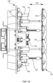
- Figures 9 and 10 illustrate side elevation views of the system as shown in Figure 8 .
- the output lens module 130 containing an array of lenses 134 and 132 is positioned close to the light guides 104 and optical softening diffuser system 120 on the central light engine module.
- the central light engine module (light engine 120) is of the reduced homogenization type in a center position. In other embodiments this type of module can be placed in a non central location. In further embodiments there may be more than one of these types of light engines 120.
- the reduced homogenizing module may include an electable diffusion module so that its light may be included in a full wash light mode
- a full wash light mode can be achieved by a reduced homogenizing light module without a diffuser but a system that dims to dim out such light modules during a full wash light mode. This dimming may be automatically tied in operation when the user selects a full wash mode or in other embodiments it might be manual.
- all of the modules are of the reduced homogenization type and they all have selectable diffusion module(s).
- the individual light engine modules are controlled individually and in other embodiments the modules are controlled in groups. The groups may be of like with like or of like geometric location in the array such as outer ring, inner ring, etc. These controls may include a color intensity diffusion flag if so equipped, image multiplier if so equipped, and zoom lens if mechanically configured to be independently controllable (not shown in the figures).
- optical diffusers 28 and 30 are not positioned across the beam in light engine 120 then the lens when it is in its distant, narrow angle, position may be focused on the LED and the multiple internal reflections in light guides optically multiply the chip shape which creates a sharp distinct flower effect. If the lens is moved to the close, wide angle, position then, even without the diffusers 28 and 30 in place, light engine 120 will produce a smoother wash style beam with a less distinct flower effect. In either case, with diffuser 28 or 30 in place the system in light engine 120 will produce a smooth homogenized effect, without the flower effect.
- the movement of output lens module 130 is produced by motors 106 acting on lead screws 108.
- motors 106 acting on lead screws 108.
- the output lens module 130 is supported by guides 110 such that the motion is constrained to be back and forth along the optical axis of the luminaire.
- any lenses associated with LED light sources that are fitted with optical softening diffuser system 120 such as the central light engine module in Figure 7 , may move with the output lens module 130, may be fitted with independent motor control separate from that for the output lens module 130, or may be static with a fixed beam angle.
- the design of lenses 132 and 134 in output lens module 130 is such that the individual homogenized beams of light from each of the light beams emitted from the light guides 104 are constrained to further overlap and mix as they leave the output lens module 130 providing a smooth, contiguous light beam with a wash light distribution with a large effective source (comprising the total output lens module 130) and true blending output distribution.
- Figure 11 illustrates a complete automated luminaire 150as may be used in a lighting system such as that illustrated in Figure 1 .
- Lens array 130 is visible on the external face of the automated luminaire 150.
- Figure 12 illustrates a further embodiment of the output lenses 134 or 132 as may be used in the described system.
- edge lens 134 comprises a single element constructed, by the use of aspheric surfaces or otherwise, to exhibit achromatic properties.
- the edge lens 134 does not have a smooth surface, instead there is a microstructure on the lens surface or surfaces. The lens surface or surfaces are covered with small engineered depressions similar to those on a golf ball.
- the depressions 140 are shown here larger than in reality for ease of illustration.
- the depressions 140 may be 0.3 mm (millimeter) - 0.4 mm in diameter with a depth of only 0.0001 mm.
- These depressions 140, along with the use of aspheric lens surfaces, may be used on one or both sides of edge lens 134 so as to provide achromatic operation of the lens.
- the LED sources feeding light guides 104 and optical softening diffuser system 120 may be individually or collectively controlled as to color and intensity to provide either a coordinated wash light or an effects unit as desired.
- any LED sources fitted with optical softening diffuser system 120 may be controlled such that either they produce the aforementioned dynamic flower effect, or produce a smooth wash beam to match standard light guides 104. The operator may choose to combine or mix these effects to achieve a desired result.
Landscapes
- Engineering & Computer Science (AREA)
- General Engineering & Computer Science (AREA)
- Non-Portable Lighting Devices Or Systems Thereof (AREA)
Claims (10)
- Eine automatische Leuchte, die Folgendes beinhaltet:ein erstes, mittiges Light-Engine-Modul (120), das Folgendes beinhaltet:eine erste Leuchtdioden(LED)-Array-Quelle (20), die dazu konfiguriert ist, eine erste Vielzahl von farbigen Lichtstrahlen auszustrahlen;einen ersten Lichtleiter (22), der optisch mit der ersten LED-Array-Quelle gekoppelt ist und dazu konfiguriert ist, die von der ersten LED-Array-Quelle ausgestrahlte erste Vielzahl von farbigen Lichtstrahlen zu empfangen und einen ersten homogenisierten Lichtstrahl auszustrahlen, wobei der erste homogenisierte Lichtstrahl eine sichtbare Trennung mindestens einiger der empfangenen ersten Vielzahl von farbigen Lichtstrahlen umfasst; undeine erste Linse (40, 132), die optisch mit dem ersten Lichtleiter gekoppelt ist und dazu konfiguriert ist, den ersten homogenisierten Lichtstrahl zu empfangen und sich entlang einer optischen Achse des ersten Lichtleiters zu bewegen, wobei die erste Linse (40, 132) dazu konfiguriert ist, ein Muster der sichtbar getrennten farbigen Lichtstrahlen in dem ersten homogenisierten Lichtstrahl zu projizieren, wobei das Muster seine Größe ändert, während sich die erste Linse entlang der optischen Achse des ersten Lichtleiters bewegt; undeine Vielzahl von zweiten, nicht mittigen Light-Engine-Modulen (104), die das erste Light-Engine-Modul umgeben, wobei die zweiten Light-Engine-Module jeweils Folgendes beinhalten:eine zweite LED-Array-Quelle (20), die dazu konfiguriert ist, eine zweite Vielzahl von farbigen Lichtstrahlen auszustrahlen;eine Vielzahl von zweiten Lichtleitern (22), die optisch mit den zweiten LED-Array-Lichtquellen gekoppelt sind und dazu konfiguriert sind, jeweils die von den zweiten LED-Array-Lichtquellen ausgestrahlte zweite Vielzahl von farbigen Lichtstrahlen zu empfangen und einen zweiten homogenisierten Lichtstrahl auszustrahlen, wobei die zweiten Lichtleiter homogenisierender sind als der erste Lichtleiter; undeine Vielzahl von zweiten Linsen (134), die optisch mit den zweiten Lichtleitem (22) gekoppelt sind und dazu konfiguriert sind, jeweils einen zweiten homogenisierten Lichtstrahl zu empfangen und sich entlang einer optischen Achse der zweiten Lichtleiter zu bewegen, wobei die zweiten Linsen jeweils einen Lichtstrahl projizieren, der einen durch einen Abstand der zweiten Line von dem zweiten Lichtleiter bestimmten Strahlwinkel aufweist;wobei die Vielzahl der Linsen (40,120) ein Zoom-Linsensystem definiert;wobei das Zoom-Linsensystem dazu konfiguriert ist, das empfangene Licht mit einem blumenähnlichen Effekt zu projizieren.
- Automatische Leuchte gemäß Anspruch 1, wobei der erste Lichtleiter (22) dazu konfiguriert ist, sich um die Lichtstrahlachse zu drehen.
- Automatische Leuchte gemäß Anspruch 1, wobei mindestens ein Light-Engine-Modul von dem ersten Light-Engine-Modul und der Vielzahl von zweiten Light-Engine-Modulen einen bildmultiplizierenden optischen Modulator beinhaltet, der dazu konfiguriert ist, in den von dem Lichtleiter des mindestens einen Light-Engine-Moduls ausgestrahlten Lichtstrahl bewegt zu werden.
- Automatische Leuchte gemäß Anspruch 1, wobei mindestens ein Light-Engine-Modul von dem ersten Light-Engine-Modul und der Vielzahl von zweiten Light-Engine-Modulen einen Diffusor (28, 30) beinhaltet, der dazu konfiguriert ist, in den von dem Lichtleiter (22) des mindestens einen Light-Engine-Moduls ausgestrahlten Lichtstrahl bewegt zu werden.
- Automatische Leuchte gemäß Anspruch 1, wobei mindestens eine Linse von der ersten Linse und den zweiten Linsen der Vielzahl von zweiten Light-Engine-Modulen eine eine Vielzahl von Vertiefungen (140) umfassende Oberfläche beinhaltet.
- Automatische Leuchte gemäß Anspruch 1, wobei die zweiten Linsen der Vielzahl von zweiten Light-Engine-Modulen mechanisch gekoppelt sind und sich miteinander relativ zu ihren zugehörigen zweiten Lichtleitern bewegen.
- Automatische Leuchte gemäß Anspruch 1, wobei das erste Light-Engine-Modul eines einer Vielzahl von ersten Light-Engine-Modulen ist.
- Automatische Leuchte gemäß einem der Ansprüche 1, 2, 3, 4, 6 oder 7, die ferner Folgendes beinhaltet:
Steuerelektronik, die mit dem ersten Light-Engine-Modul und der Vielzahl von zweiten Light-Engine-Modulen gekoppelt ist und dazu konfiguriert ist, das erste Light-Engine-Modul und die Vielzahl von zweiten Light-Engine-Modulen zu steuern. - Automatische Leuchte gemäß Anspruch 8, wobei die Steuerelektronik dazu konfiguriert ist, eine Helligkeit von einer oder mehreren LEDs in der ersten LED-Array-Quelle einzeln zu steuern und eine Helligkeit einer oder mehrerer LEDs in jeder der zweiten LED-Array-Quellen einzeln zu steuern.
- Automatische Leuchte gemäß Anspruch 1, wobei die Lichtleiter einen Kollimationsstab beinhalten.
Applications Claiming Priority (2)
| Application Number | Priority Date | Filing Date | Title |
|---|---|---|---|
| US15/089,116 US10132992B2 (en) | 2016-03-20 | 2016-04-01 | Special flower effects beam and washlight luminaire |
| PCT/US2017/025658 WO2017173429A1 (en) | 2016-04-01 | 2017-04-01 | A special flower effects beam and washlight luminaire |
Publications (2)
| Publication Number | Publication Date |
|---|---|
| EP3436740A1 EP3436740A1 (de) | 2019-02-06 |
| EP3436740B1 true EP3436740B1 (de) | 2025-05-28 |
Family
ID=59227804
Family Applications (1)
| Application Number | Title | Priority Date | Filing Date |
|---|---|---|---|
| EP17733564.3A Active EP3436740B1 (de) | 2016-04-01 | 2017-04-01 | Eine wash light leuchte mit spezialeffekten |
Country Status (3)
| Country | Link |
|---|---|
| EP (1) | EP3436740B1 (de) |
| CN (1) | CN109312902B (de) |
| WO (1) | WO2017173429A1 (de) |
Families Citing this family (2)
| Publication number | Priority date | Publication date | Assignee | Title |
|---|---|---|---|---|
| DE102020134279A1 (de) * | 2020-12-18 | 2022-06-23 | Bartenbach Holding Gmbh | Zoom-Strahler |
| CN217109290U (zh) * | 2022-03-31 | 2022-08-02 | 广州市浩洋电子股份有限公司 | 一种具有除雾装置的舞台灯 |
Citations (3)
| Publication number | Priority date | Publication date | Assignee | Title |
|---|---|---|---|---|
| EP2177816A2 (de) * | 2008-10-20 | 2010-04-21 | ROBE lighting s.r.o. | Lichtsammelsystem für eine LED-Leuchte |
| EP1550908B1 (de) * | 2002-10-09 | 2014-07-23 | Panasonic Corporation | Illuminator und projektionsbildanzeige damit |
| WO2015022644A1 (en) * | 2013-08-12 | 2015-02-19 | Clay Paky S.P.A. | Stage light fixture, in particular multisource stage light fixture |
Family Cites Families (7)
| Publication number | Priority date | Publication date | Assignee | Title |
|---|---|---|---|---|
| JP4494045B2 (ja) * | 2003-03-11 | 2010-06-30 | 株式会社半導体エネルギー研究所 | ビームホモジナイザ及びレーザ照射装置、並びに半導体装置の作製方法 |
| JP2012522349A (ja) * | 2009-03-31 | 2012-09-20 | コーニンクレッカ フィリップス エレクトロニクス エヌ ヴィ | Led平行化光学モジュール及び該モジュールを使用する照明器具 |
| CN102095086B (zh) * | 2009-12-11 | 2013-02-20 | 李金宗 | 匀光器及其光纤面板的用途 |
| DK177579B1 (en) * | 2010-04-23 | 2013-10-28 | Martin Professional As | Led light fixture with background lighting |
| EP2920507B1 (de) * | 2012-08-20 | 2018-04-18 | ROBE lighting s.r.o. | Leuchte mit gelenkigem länglichem lichtstrahlhomogenisierer |
| US20160298813A1 (en) * | 2013-10-01 | 2016-10-13 | Robe Lighting | Multiple color homogenization system for an led luminaire |
| US20160246040A1 (en) * | 2014-03-10 | 2016-08-25 | Robe Lighting Sro | Optical system for an led luminaire |
-
2017
- 2017-04-01 CN CN201780034567.2A patent/CN109312902B/zh active Active
- 2017-04-01 EP EP17733564.3A patent/EP3436740B1/de active Active
- 2017-04-01 WO PCT/US2017/025658 patent/WO2017173429A1/en not_active Ceased
Patent Citations (3)
| Publication number | Priority date | Publication date | Assignee | Title |
|---|---|---|---|---|
| EP1550908B1 (de) * | 2002-10-09 | 2014-07-23 | Panasonic Corporation | Illuminator und projektionsbildanzeige damit |
| EP2177816A2 (de) * | 2008-10-20 | 2010-04-21 | ROBE lighting s.r.o. | Lichtsammelsystem für eine LED-Leuchte |
| WO2015022644A1 (en) * | 2013-08-12 | 2015-02-19 | Clay Paky S.P.A. | Stage light fixture, in particular multisource stage light fixture |
Also Published As
| Publication number | Publication date |
|---|---|
| WO2017173429A1 (en) | 2017-10-05 |
| CN109312902A (zh) | 2019-02-05 |
| CN109312902B (zh) | 2020-10-20 |
| EP3436740A1 (de) | 2019-02-06 |
Similar Documents
| Publication | Publication Date | Title |
|---|---|---|
| US10690842B2 (en) | Wash light luminaire with special effects capabilities | |
| EP3433534B1 (de) | Beam- und washlight-leuchte mit speziellem blumeneffekt | |
| EP3052982B1 (de) | Kollimierungs- und homogenisierungssystem für eine led-leuchte | |
| EP4092316A1 (de) | Led-lichtmaschine mit integriertem farbsystem | |
| US10018338B2 (en) | Luminaire with articulated LEDS | |
| EP3227601B1 (de) | Kollimierungs- und homogenisierungssystem für eine led-leuchte | |
| US20160245490A1 (en) | Luminaire with articulated leds | |
| EP2856236A1 (de) | Kollimierungs- und homogenisierungssystem für eine led-leuchte | |
| EP3052981A2 (de) | Mehrfarbhomogenisierungssystem für eine led-leuchte | |
| US20170074489A1 (en) | System and method for controlling light output in a led luminaire | |
| US20160298829A1 (en) | System and method for controlling light output in a led luminaire | |
| US10408402B2 (en) | Optical system for a LED luminaire | |
| EP3436740B1 (de) | Eine wash light leuchte mit spezialeffekten | |
| US20180313521A1 (en) | System and method for controlling output in a led luminaire | |
| EP3433535B1 (de) | System und verfahren zur steuerung der lichtleistung in einem led licht | |
| WO2017165685A1 (en) | Optical system for an led luminaire | |
| WO2017165686A1 (en) | Luminaire with articulated leds |
Legal Events
| Date | Code | Title | Description |
|---|---|---|---|
| STAA | Information on the status of an ep patent application or granted ep patent |
Free format text: STATUS: UNKNOWN |
|
| STAA | Information on the status of an ep patent application or granted ep patent |
Free format text: STATUS: THE INTERNATIONAL PUBLICATION HAS BEEN MADE |
|
| PUAI | Public reference made under article 153(3) epc to a published international application that has entered the european phase |
Free format text: ORIGINAL CODE: 0009012 |
|
| STAA | Information on the status of an ep patent application or granted ep patent |
Free format text: STATUS: REQUEST FOR EXAMINATION WAS MADE |
|
| 17P | Request for examination filed |
Effective date: 20181019 |
|
| AK | Designated contracting states |
Kind code of ref document: A1 Designated state(s): AL AT BE BG CH CY CZ DE DK EE ES FI FR GB GR HR HU IE IS IT LI LT LU LV MC MK MT NL NO PL PT RO RS SE SI SK SM TR |
|
| AX | Request for extension of the european patent |
Extension state: BA ME |
|
| DAV | Request for validation of the european patent (deleted) | ||
| DAX | Request for extension of the european patent (deleted) | ||
| RAP1 | Party data changed (applicant data changed or rights of an application transferred) |
Owner name: ROBE LIGHTING S.R.O. |
|
| RIN1 | Information on inventor provided before grant (corrected) |
Inventor name: JURIK, PAVEL Inventor name: VALCHAR, JOSEF |
|
| REG | Reference to a national code |
Ref country code: HK Ref legal event code: DE Ref document number: 1259814 Country of ref document: HK |
|
| STAA | Information on the status of an ep patent application or granted ep patent |
Free format text: STATUS: EXAMINATION IS IN PROGRESS |
|
| 17Q | First examination report despatched |
Effective date: 20191210 |
|
| P01 | Opt-out of the competence of the unified patent court (upc) registered |
Effective date: 20230523 |
|
| RAP3 | Party data changed (applicant data changed or rights of an application transferred) |
Owner name: ROBE LIGHTING S.R.O. |
|
| GRAP | Despatch of communication of intention to grant a patent |
Free format text: ORIGINAL CODE: EPIDOSNIGR1 |
|
| STAA | Information on the status of an ep patent application or granted ep patent |
Free format text: STATUS: GRANT OF PATENT IS INTENDED |
|
| INTG | Intention to grant announced |
Effective date: 20241025 |
|
| GRAS | Grant fee paid |
Free format text: ORIGINAL CODE: EPIDOSNIGR3 |
|
| GRAA | (expected) grant |
Free format text: ORIGINAL CODE: 0009210 |
|
| STAA | Information on the status of an ep patent application or granted ep patent |
Free format text: STATUS: THE PATENT HAS BEEN GRANTED |
|
| AK | Designated contracting states |
Kind code of ref document: B1 Designated state(s): AL AT BE BG CH CY CZ DE DK EE ES FI FR GB GR HR HU IE IS IT LI LT LU LV MC MK MT NL NO PL PT RO RS SE SI SK SM TR |
|
| REG | Reference to a national code |
Ref country code: GB Ref legal event code: FG4D |
|
| REG | Reference to a national code |
Ref country code: CH Ref legal event code: EP |
|
| REG | Reference to a national code |
Ref country code: DE Ref legal event code: R096 Ref document number: 602017089671 Country of ref document: DE |
|
| REG | Reference to a national code |
Ref country code: IE Ref legal event code: FG4D |
|
| REG | Reference to a national code |
Ref country code: NL Ref legal event code: FP |
|
| PG25 | Lapsed in a contracting state [announced via postgrant information from national office to epo] |
Ref country code: FI Free format text: LAPSE BECAUSE OF FAILURE TO SUBMIT A TRANSLATION OF THE DESCRIPTION OR TO PAY THE FEE WITHIN THE PRESCRIBED TIME-LIMIT Effective date: 20250528 Ref country code: ES Free format text: LAPSE BECAUSE OF FAILURE TO SUBMIT A TRANSLATION OF THE DESCRIPTION OR TO PAY THE FEE WITHIN THE PRESCRIBED TIME-LIMIT Effective date: 20250528 |
|
| REG | Reference to a national code |
Ref country code: LT Ref legal event code: MG9D |
|
| PG25 | Lapsed in a contracting state [announced via postgrant information from national office to epo] |
Ref country code: NO Free format text: LAPSE BECAUSE OF FAILURE TO SUBMIT A TRANSLATION OF THE DESCRIPTION OR TO PAY THE FEE WITHIN THE PRESCRIBED TIME-LIMIT Effective date: 20250828 Ref country code: GR Free format text: LAPSE BECAUSE OF FAILURE TO SUBMIT A TRANSLATION OF THE DESCRIPTION OR TO PAY THE FEE WITHIN THE PRESCRIBED TIME-LIMIT Effective date: 20250829 |
|
| PG25 | Lapsed in a contracting state [announced via postgrant information from national office to epo] |
Ref country code: PL Free format text: LAPSE BECAUSE OF FAILURE TO SUBMIT A TRANSLATION OF THE DESCRIPTION OR TO PAY THE FEE WITHIN THE PRESCRIBED TIME-LIMIT Effective date: 20250528 |
|
| PG25 | Lapsed in a contracting state [announced via postgrant information from national office to epo] |
Ref country code: BG Free format text: LAPSE BECAUSE OF FAILURE TO SUBMIT A TRANSLATION OF THE DESCRIPTION OR TO PAY THE FEE WITHIN THE PRESCRIBED TIME-LIMIT Effective date: 20250528 |
|
| PG25 | Lapsed in a contracting state [announced via postgrant information from national office to epo] |
Ref country code: HR Free format text: LAPSE BECAUSE OF FAILURE TO SUBMIT A TRANSLATION OF THE DESCRIPTION OR TO PAY THE FEE WITHIN THE PRESCRIBED TIME-LIMIT Effective date: 20250528 |
|
| PG25 | Lapsed in a contracting state [announced via postgrant information from national office to epo] |
Ref country code: RS Free format text: LAPSE BECAUSE OF FAILURE TO SUBMIT A TRANSLATION OF THE DESCRIPTION OR TO PAY THE FEE WITHIN THE PRESCRIBED TIME-LIMIT Effective date: 20250828 |
|
| PG25 | Lapsed in a contracting state [announced via postgrant information from national office to epo] |
Ref country code: IS Free format text: LAPSE BECAUSE OF FAILURE TO SUBMIT A TRANSLATION OF THE DESCRIPTION OR TO PAY THE FEE WITHIN THE PRESCRIBED TIME-LIMIT Effective date: 20250928 |
|
| PG25 | Lapsed in a contracting state [announced via postgrant information from national office to epo] |
Ref country code: LV Free format text: LAPSE BECAUSE OF FAILURE TO SUBMIT A TRANSLATION OF THE DESCRIPTION OR TO PAY THE FEE WITHIN THE PRESCRIBED TIME-LIMIT Effective date: 20250528 |
|
| REG | Reference to a national code |
Ref country code: AT Ref legal event code: MK05 Ref document number: 1798756 Country of ref document: AT Kind code of ref document: T Effective date: 20250528 |
|
| PG25 | Lapsed in a contracting state [announced via postgrant information from national office to epo] |
Ref country code: DK Free format text: LAPSE BECAUSE OF FAILURE TO SUBMIT A TRANSLATION OF THE DESCRIPTION OR TO PAY THE FEE WITHIN THE PRESCRIBED TIME-LIMIT Effective date: 20250528 Ref country code: SM Free format text: LAPSE BECAUSE OF FAILURE TO SUBMIT A TRANSLATION OF THE DESCRIPTION OR TO PAY THE FEE WITHIN THE PRESCRIBED TIME-LIMIT Effective date: 20250528 Ref country code: AT Free format text: LAPSE BECAUSE OF FAILURE TO SUBMIT A TRANSLATION OF THE DESCRIPTION OR TO PAY THE FEE WITHIN THE PRESCRIBED TIME-LIMIT Effective date: 20250528 |
|
| PG25 | Lapsed in a contracting state [announced via postgrant information from national office to epo] |
Ref country code: CZ Free format text: LAPSE BECAUSE OF FAILURE TO SUBMIT A TRANSLATION OF THE DESCRIPTION OR TO PAY THE FEE WITHIN THE PRESCRIBED TIME-LIMIT Effective date: 20250528 |
|
| PG25 | Lapsed in a contracting state [announced via postgrant information from national office to epo] |
Ref country code: EE Free format text: LAPSE BECAUSE OF FAILURE TO SUBMIT A TRANSLATION OF THE DESCRIPTION OR TO PAY THE FEE WITHIN THE PRESCRIBED TIME-LIMIT Effective date: 20250528 |
|
| PG25 | Lapsed in a contracting state [announced via postgrant information from national office to epo] |
Ref country code: RO Free format text: LAPSE BECAUSE OF FAILURE TO SUBMIT A TRANSLATION OF THE DESCRIPTION OR TO PAY THE FEE WITHIN THE PRESCRIBED TIME-LIMIT Effective date: 20250528 Ref country code: SK Free format text: LAPSE BECAUSE OF FAILURE TO SUBMIT A TRANSLATION OF THE DESCRIPTION OR TO PAY THE FEE WITHIN THE PRESCRIBED TIME-LIMIT Effective date: 20250528 |
|
| PG25 | Lapsed in a contracting state [announced via postgrant information from national office to epo] |
Ref country code: IT Free format text: LAPSE BECAUSE OF FAILURE TO SUBMIT A TRANSLATION OF THE DESCRIPTION OR TO PAY THE FEE WITHIN THE PRESCRIBED TIME-LIMIT Effective date: 20250528 |
|
| REG | Reference to a national code |
Ref country code: DE Ref legal event code: R097 Ref document number: 602017089671 Country of ref document: DE |
|
| PLBE | No opposition filed within time limit |
Free format text: ORIGINAL CODE: 0009261 |
|
| STAA | Information on the status of an ep patent application or granted ep patent |
Free format text: STATUS: NO OPPOSITION FILED WITHIN TIME LIMIT |
|
| PGFP | Annual fee paid to national office [announced via postgrant information from national office to epo] |
Ref country code: GB Payment date: 20260319 Year of fee payment: 10 |
|
| REG | Reference to a national code |
Ref country code: CH Ref legal event code: L10 Free format text: ST27 STATUS EVENT CODE: U-0-0-L10-L00 (AS PROVIDED BY THE NATIONAL OFFICE) Effective date: 20260409 |
|
| PGFP | Annual fee paid to national office [announced via postgrant information from national office to epo] |
Ref country code: BE Payment date: 20260319 Year of fee payment: 10 |
|
| PGFP | Annual fee paid to national office [announced via postgrant information from national office to epo] |
Ref country code: NL Payment date: 20260319 Year of fee payment: 10 |
|
| PGFP | Annual fee paid to national office [announced via postgrant information from national office to epo] |
Ref country code: FR Payment date: 20260319 Year of fee payment: 10 |