EP3435798B1 - Vorrichtung zum erhitzen von aerosolerzeugendem material und patrone für die vorrichtung - Google Patents
Vorrichtung zum erhitzen von aerosolerzeugendem material und patrone für die vorrichtung Download PDFInfo
- Publication number
- EP3435798B1 EP3435798B1 EP17717339.0A EP17717339A EP3435798B1 EP 3435798 B1 EP3435798 B1 EP 3435798B1 EP 17717339 A EP17717339 A EP 17717339A EP 3435798 B1 EP3435798 B1 EP 3435798B1
- Authority
- EP
- European Patent Office
- Prior art keywords
- base
- cartridge
- cover
- aerosol generating
- heater
- Prior art date
- Legal status (The legal status is an assumption and is not a legal conclusion. Google has not performed a legal analysis and makes no representation as to the accuracy of the status listed.)
- Active
Links
Images


Classifications
-
- A—HUMAN NECESSITIES
- A24—TOBACCO; CIGARS; CIGARETTES; SIMULATED SMOKING DEVICES; SMOKERS' REQUISITES
- A24F—SMOKERS' REQUISITES; MATCH BOXES; SIMULATED SMOKING DEVICES
- A24F40/00—Electrically operated smoking devices; Component parts thereof; Manufacture thereof; Maintenance or testing thereof; Charging means specially adapted therefor
- A24F40/30—Devices using two or more structurally separated inhalable precursors, e.g. using two liquid precursors in two cartridges
-
- A—HUMAN NECESSITIES
- A24—TOBACCO; CIGARS; CIGARETTES; SIMULATED SMOKING DEVICES; SMOKERS' REQUISITES
- A24F—SMOKERS' REQUISITES; MATCH BOXES; SIMULATED SMOKING DEVICES
- A24F47/00—Smokers' requisites not otherwise provided for
-
- A—HUMAN NECESSITIES
- A24—TOBACCO; CIGARS; CIGARETTES; SIMULATED SMOKING DEVICES; SMOKERS' REQUISITES
- A24F—SMOKERS' REQUISITES; MATCH BOXES; SIMULATED SMOKING DEVICES
- A24F40/00—Electrically operated smoking devices; Component parts thereof; Manufacture thereof; Maintenance or testing thereof; Charging means specially adapted therefor
- A24F40/40—Constructional details, e.g. connection of cartridges and battery parts
- A24F40/42—Cartridges or containers for inhalable precursors
-
- A—HUMAN NECESSITIES
- A24—TOBACCO; CIGARS; CIGARETTES; SIMULATED SMOKING DEVICES; SMOKERS' REQUISITES
- A24F—SMOKERS' REQUISITES; MATCH BOXES; SIMULATED SMOKING DEVICES
- A24F40/00—Electrically operated smoking devices; Component parts thereof; Manufacture thereof; Maintenance or testing thereof; Charging means specially adapted therefor
- A24F40/40—Constructional details, e.g. connection of cartridges and battery parts
- A24F40/46—Shape or structure of electric heating means
-
- A—HUMAN NECESSITIES
- A61—MEDICAL OR VETERINARY SCIENCE; HYGIENE
- A61M—DEVICES FOR INTRODUCING MEDIA INTO, OR ONTO, THE BODY; DEVICES FOR TRANSDUCING BODY MEDIA OR FOR TAKING MEDIA FROM THE BODY; DEVICES FOR PRODUCING OR ENDING SLEEP OR STUPOR
- A61M11/00—Sprayers or atomisers specially adapted for therapeutic purposes
- A61M11/04—Sprayers or atomisers specially adapted for therapeutic purposes operated by the vapour pressure of the liquid to be sprayed or atomised
- A61M11/041—Sprayers or atomisers specially adapted for therapeutic purposes operated by the vapour pressure of the liquid to be sprayed or atomised using heaters
- A61M11/042—Sprayers or atomisers specially adapted for therapeutic purposes operated by the vapour pressure of the liquid to be sprayed or atomised using heaters electrical
-
- A—HUMAN NECESSITIES
- A61—MEDICAL OR VETERINARY SCIENCE; HYGIENE
- A61M—DEVICES FOR INTRODUCING MEDIA INTO, OR ONTO, THE BODY; DEVICES FOR TRANSDUCING BODY MEDIA OR FOR TAKING MEDIA FROM THE BODY; DEVICES FOR PRODUCING OR ENDING SLEEP OR STUPOR
- A61M15/00—Inhalators
- A61M15/0028—Inhalators using prepacked dosages, one for each application, e.g. capsules to be perforated or broken-up
-
- A—HUMAN NECESSITIES
- A61—MEDICAL OR VETERINARY SCIENCE; HYGIENE
- A61M—DEVICES FOR INTRODUCING MEDIA INTO, OR ONTO, THE BODY; DEVICES FOR TRANSDUCING BODY MEDIA OR FOR TAKING MEDIA FROM THE BODY; DEVICES FOR PRODUCING OR ENDING SLEEP OR STUPOR
- A61M15/00—Inhalators
- A61M15/06—Inhaling appliances shaped like cigars, cigarettes or pipes
-
- A—HUMAN NECESSITIES
- A24—TOBACCO; CIGARS; CIGARETTES; SIMULATED SMOKING DEVICES; SMOKERS' REQUISITES
- A24F—SMOKERS' REQUISITES; MATCH BOXES; SIMULATED SMOKING DEVICES
- A24F40/00—Electrically operated smoking devices; Component parts thereof; Manufacture thereof; Maintenance or testing thereof; Charging means specially adapted therefor
- A24F40/10—Devices using liquid inhalable precursors
-
- A—HUMAN NECESSITIES
- A61—MEDICAL OR VETERINARY SCIENCE; HYGIENE
- A61M—DEVICES FOR INTRODUCING MEDIA INTO, OR ONTO, THE BODY; DEVICES FOR TRANSDUCING BODY MEDIA OR FOR TAKING MEDIA FROM THE BODY; DEVICES FOR PRODUCING OR ENDING SLEEP OR STUPOR
- A61M15/00—Inhalators
- A61M15/0028—Inhalators using prepacked dosages, one for each application, e.g. capsules to be perforated or broken-up
- A61M15/003—Inhalators using prepacked dosages, one for each application, e.g. capsules to be perforated or broken-up using capsules, e.g. to be perforated or broken-up
- A61M15/0033—Details of the piercing or cutting means
- A61M15/0035—Piercing means
- A61M15/0036—Piercing means hollow piercing means
-
- A—HUMAN NECESSITIES
- A61—MEDICAL OR VETERINARY SCIENCE; HYGIENE
- A61M—DEVICES FOR INTRODUCING MEDIA INTO, OR ONTO, THE BODY; DEVICES FOR TRANSDUCING BODY MEDIA OR FOR TAKING MEDIA FROM THE BODY; DEVICES FOR PRODUCING OR ENDING SLEEP OR STUPOR
- A61M2205/00—General characteristics of the apparatus
- A61M2205/33—Controlling, regulating or measuring
- A61M2205/3331—Pressure; Flow
- A61M2205/3334—Measuring or controlling the flow rate
-
- A—HUMAN NECESSITIES
- A61—MEDICAL OR VETERINARY SCIENCE; HYGIENE
- A61M—DEVICES FOR INTRODUCING MEDIA INTO, OR ONTO, THE BODY; DEVICES FOR TRANSDUCING BODY MEDIA OR FOR TAKING MEDIA FROM THE BODY; DEVICES FOR PRODUCING OR ENDING SLEEP OR STUPOR
- A61M2205/00—General characteristics of the apparatus
- A61M2205/82—Internal energy supply devices
- A61M2205/8206—Internal energy supply devices battery-operated
Definitions
- the present invention relates to apparatus arranged to heat aerosol generating material and a cartridge for the apparatus.
- Smoking articles such as cigarettes, cigars and the like burn tobacco during use to create tobacco smoke. Attempts have been made to provide alternatives to these smoking articles by creating products that release compounds without actually combusting and hence which do not create smoke or an aerosol as a result of degradation of, for example, tobacco by combustion or the process of burning. Examples of such products are so-called heat-not-burn products, tobacco heating products or tobacco heating devices, which release compounds, which may form an aerosol, by heating, but not burning, aerosol generating material.
- the aerosol generating material may be for example tobacco or other non-tobacco products, which may or may not contain nicotine.
- WO2015/116934 describes a container pod comprising a chamber wall defining an internal volume within which an herbal composition is received.
- the container pod is received within a vaporizer device.
- CA2937974 describes an aerosol generating device and a removable cartridge.
- the device defines a cavity for receiving the cartridge.
- the cartridge comprises a cylindrical housing and contains capillary material comprising liquid aerosol forming substrate.
- the sheet of heat conductive material may be flexible and may comprise metal foil. In other example, the sheet of heat conductive material may be non-flexible.
- the first body may comprise a first cover attached to the first base, wherein the first cover and the first base define the first chamber.
- the first cover may comprise a plastics or polymide material.
- the first body comprises an inlet for enabling air to flow into the first chamber and an outlet, spaced apart from the inlet, to enable at least one volatilised component of the aerosol generating material and/or an aerosol to flow out of the first chamber.
- the first base and the second base may be connected together to enable relative pivotal movement of the first base and the second base so that a user can bring the first outer surface into contact with the first heating surface of the heater and the second outer surface into contact with the second heating surface of the heater.
- the first base and the second base may be connected along a first line of weakening to enable the relative pivotal movement.
- the first base and the second base may be, in a pre-use configuration, connected at respective sides of the first base and the second base that are substantially perpendicular to a longitudinal axis of the cartridge.
- the second body may comprise a second cover attached to the second base, wherein the second cover and the second base define the second chamber and wherein, the first cover and the second cover are, in the pre-use configuration, connected along a second line of weakening which ruptures when the first base and the second base undergo relative pivotable movement, whereby the first cover and the second cover are separated to provide an a volatilised material and/or aerosol outlet for the first cover and a volatilised material and/or aerosol outlet for the second cover.
- the first base may comprise a first piercer for piercing the second base to provide an air inlet for the second chamber and the second base may comprise a second piercer for piercing the first base to provide an air inlet for the first chamber.
- the first base and the second base may be, in a pre-use configuration, connected at respective sides of the first base and the second base that that are substantially parallel to a longitudinal axis of the cartridge.
- the heater may comprise a heating plate that comprises the first heating surface.
- the first heating surface may be convex.
- the apparatus may further comprise a mouthpiece having a mouthpiece outlet and wherein the housing comprises at least one air inlet, wherein in use, when a user draws on the outlet of the mouthpiece, air flows through the at least one air inlet of the housing and through an inlet of the first body and a mixture of air and at least one volatilised component of the aerosol generating material and/or aerosol flows out of an outlet of the first body.
- the apparatus may comprise a first piercer for piercing the first body when the cartridge is inserted in the apparatus to provide one of the inlet of the first body and the outlet of the first body.
- the apparatus may comprise a second piercer for piercing the first body when the cartridge is inserted in the apparatus to provide the other of the inlet of the first body and the outlet of the first body.
- the apparatus may comprise a second piercer for piercing the first body when the cartridge is inserted in the apparatus to provide the other of the inlet of the first body and the outlet of the first body.
- the heater may be a heater plate that defines the first heating surface and a second heating surface, wherein the first and second heating surfaces are opposite surfaces of the heater plate, and wherein the second heating surface is for contacting at least a major portion of a second heat conductive base of a second body of the cartridge that is insertable into the housing, whereby in use, the heater heats aerosol generating material in a chamber defined by the first body and a chamber defined by the second body to volatilise at least one component of the aerosol generating material in the chambers.
- the term "aerosol generating material” includes materials that provide volatilised components upon heating.
- “Aerosol generating material” includes any tobacco-containing material and may, for example, include one or more of tobacco, tobacco derivatives including tobacco extracts, expanded tobacco, reconstituted tobacco or tobacco substitutes.
- "Aerosol generating material” also may include other, non-tobacco, products, including for example flavourants, which, depending on the product, may or may not contain nicotine, filler materials such as chalk and/or sorbent materials, glycerol, propylene glycol or triacetin.
- the aerosol generating material may also include a binding material, for example, sodium alginate.
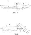
- FIG. 1 there is shown a first example of an apparatus 1 and a cartridge 100 that is insertable within the apparatus 1.
- the apparatus 1 is arranged to heat aerosol generating material (not shown) contained within the cartridge 100 when the cartridge 100 is inserted inside the apparatus 1 to volatilise at least one component of the aerosol generating material.
- the apparatus 1 is a so-called "tobacco-heating-product" apparatus.
- the apparatus 1 in this example is generally elongate and comprises a generally tubular housing 3.
- the tubular housing 3 comprises a main housing section 5, a heater support section 7, a lid section 9 and a mouth piece 11 comprising an outlet 11a.
- These sections of the apparatus 1 may comprise any suitable material or materials, for example, plastic or metal or combinations thereof.
- the mouthpiece 11 (or at least the tip of the mouthpiece 11) may comprise a material that feels comfortable to the lips, for example, suitable plastics or silicone rubber based materials.
- the main housing section 5 comprises first 5a and second 5b longitudinal ends.
- the first end 5a defines a distal end of the whole of the apparatus 1 and the second end 5b is located at approximately just over half of the way along the length of the apparatus 1.
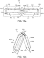
- the heater support section 7 extends from the second 5b longitudinal end of the main housing section 5 and defines a platform 7a (most clearly seen in Figures 3 , 4 and 5 ) that supports a heater13.
- the heater support section 7 may, as is the case in this example, comprise a plurality 7b, 7c of interconnected sections, one of which 7b is connected to the main housing section 5, or the heater support section 7 may be a single-piece section.
- the heater support section 7 and the lid section 9 are connected by a hinge arrangement 15 (best seen in Figure 4 ) that is arranged to enable the lid section 9 to pivot with respect to the heater support section 7, about the hinge arrangement 15, between a closed position shown in Figure 1 and an open position shown in Figures 2 to 5 .
- the lid section 9 may, as is the case in this example, comprise a plurality 9d, 9e of interconnected sections, one of which 9e is connected to the mouthpiece 11, or the lid section 9 may be a single piece section.
- the hinge arrangement 15 is arranged along an edge portion 7d of the heater support section 7 and is aligned transverse to a longitudinal axis of the apparatus 1.
- the lid section 9 When the lid section 9 is in the open position, the lid section 9 defines an open channel 8 (see Figure 3 ) into which a cartridge 100 can be inserted or from which it can be removed from by a user. When the lid section 9 is in the closed position, a cartridge 100 inserted into the channel 8 is held within the apparatus 1 against the heater 13.
- the apparatus 1 may further comprise one or more air inlets, in this example air inlet 7e formed through the section 7b, to allow air to flow into the housing 3 when a user draws on the mouthpiece 11.
- air inlet 7e formed through the section 7b
- the heater 13 comprises a thin elongate heating plate comprising a pair of opposite surfaces or faces (only one of which 13a is visible in the Figures).
- the heating plate may be formed of a heat conducting material, for example, a metal such as alumina.
- the heater 13 is arranged with its longitudinal axis parallel with that of the apparatus 1 with a first of the surfaces 13a exposed and a second of the surfaces resting flush against the support platform 7a.
- the exposed surface 13a may be curved, for example, convex or concave, and in this example, the exposed surface 13a is convex in shape.
- the heater 13 comprises a resistive heating element, for example circuitry (not shown) formed e.g. printed on the exposed surface 13a.
- the apparatus 1 further has an electronics/power chamber, within the main housing 5, which in this example contains a power source 19 and electrical control circuitry 21.
- the electrical control circuitry 21 may include a controller, such as a microprocessor arrangement, configured and arranged to control the heater 13 as discussed further below.
- the power source 19 may be a battery, which may be a rechargeable battery or a non-rechargeable battery. Examples include nickel cadmium batteries although any suitable batteries may be used.
- the battery 19 is electrically coupled to the heater 13 to supply electrical power when required and under control of the electrical control circuitry 21 to heat the aerosol generating material in the cartridge 100 (as discussed, to volatilise the aerosol generating material without causing the aerosol generating material to combust or undergo pyrolysis).
- the apparatus 1 further comprises a charging slot 5c (see Figure 3 ), in this example formed through the first end 5a of the main housing section 5 to allow a charger (not shown) to be electrically connected to the battery 19 if the battery 19 is a rechargeable battery or to connect an external device (e.g. a computer) to the control circuitry 21 to download data from the control circuitry or upload data or software to the control circuitry 21.
- a charging slot 5c in this example formed through the first end 5a of the main housing section 5 to allow a charger (not shown) to be electrically connected to the battery 19 if the battery 19 is a rechargeable battery or to connect an external device (e.g. a computer) to the control circuitry 21 to download data from the control circuitry or upload data or software to the control circuitry 21.
- the apparatus 1 may further comprise one or other or both of a manual actuator (not shown in the Figures) for example, a push button, and a control sensor (not shown in the Figures), for example an airflow sensor, each operably coupled to the control circuitry 21.
- a manual actuator for example, a push button
- a control sensor for example an airflow sensor
- the cartridge 100 comprises a protective cover 102 attached to, for example adhered to, a planar base 104.
- the cover 102 and the planar base 104 together form a first body that defines a chamber for containing the aerosol generating material (not shown).
- the base 104 is substantially parallel to a longitudinal axis of the first body.
- the planar base 104 comprises a main rectangular section 104a and identical first 104b and second 104c projections that project from respective opposite first 104d and second 104e sides of the main rectangular section 104a.
- the area of the first 104b and second 104c projections is relatively small compared to that of the main rectangular section 104a.
- the first 104b and second 104c projections are opposite each other and are arranged symmetrically about the longitudinal axis of the planar base 104.
- the protective cover 102 comprises a top surface 102a and a multi-faceted side surface 102b.
- the footprint of the protective cover 102 covers most of the planar base 104.
- the protective cover 102 covers substantially all of the first 104b and second 104c projections and most of the main rectangular section 104a.
- First 104h and second 104i relatively narrows strips of the main rectangular section 104a along third 104f and fourth 104g sides of the main rectangular section 104a are not covered by the protective cover 102.
- the planar base 104 is formed of a sheet of thermally conductive material, for example, metal foil such as aluminium foil.
- the protective cover 102 is formed of a plastic material, typically a thermoformed plastic material such as PVC or an Orientated Polyamide (OPA).
- the protective cover is multi-layered comprising an outer plastic material layer (e,g. an OPA) and an inner foil layer (e.g. Aluminium foil).
- the protective cover 102 is adhered to the planar base 104 using a suitable adhesive.
- the protective cover 102 is bonded to the planar base 104 by way of a layer of bonding lacquer, preferably a high heat resistant lacquer that is underneath the inner foil layer.
- a high heat resistant lacquer enables rapid heating at high temperatures.
- the bonding lacquer is only provided in regions where the protective cover 102 contacts the planar base 104 and is applied only on one or other of the protective cover 102 and the planar base 104. This minimises the amount of heat resistant lacquer used and makes it less likely that, in use, heating causes the lacquer to volatilise.
- the adhesive may be applied to the areas in which there is no aerosol generating material.
- the lid section 9 of the apparatus 1 comprises a pair of spaced apart parallel guide slots 9b, 9c formed in an inner surface of the lid section 9.
- One of the guide slots 9b is formed close to and runs along a first straight edge of the lid section 9 and the other of the guide slots 9c is formed close to and runs along a second straight edge of the lid section 9 that is opposite the first straight edge.
- a user aligns the third side 104f of the main rectangular section104a with the guide slot 9c and aligns the fourth side 104g of the main rectangular section 104a with the guide slot 9b (see Figure 3 ) and pushes the cartridge 100 into an inserted position in the open channel 8.
- Figure 4 shows the cartridge partially in the inserted position
- the third 104f and fourth 104g sides of the cartridge 100 are supported in the guide slots 9c, 9b.
- the lid section 9 further comprises an inner end face 9a that comprises a first protrusion 20 that extends into the inside of the lid section 9.
- the first protrusion 20 which has a sharp or pointed end, pierces a leading face of the protective cover 102.
- a second protrusion 23 is positioned on the heater support platform 7a at a location between the heater 13 and the main housing section 5.
- the second protrusion 23 extends upwardly from the heating support platform 7a.
- the second protrusion 23 which has a sharp or pointed end is brought into contact with and pierces the first projection 104b of the planar base 104.
- the closed lid section 9 effectively 'clamps' the inserted cartridge 100 against the first surface 13a of the heater 13 with at least a major portion or all of the bottom surface of the planar base 104 in contact with the first heating surface 13a.
- the planar base 104 which is flexible, deforms or curves slightly to adopt the convex shape of the heating surface 13a. This arrangement provides for a particularly good thermal contact between the first heating surface 13a and the planar base 104.
- the first protrusion 20 comprises one or more air passageways formed there through which are in fluid communication with the outlet 11a of the mouthpiece 11.
- the second protrusion 23 comprises one or more air passageways formed there through which are in fluid communication with the one or more air inlets 7e formed in the housing 3. Accordingly, the first protrusion 20 acts as an outlet of the cartridge 100 and the second protrusion 23 acts as an inlet of the cartridge 100.
- the control circuitry 21 is operated so that electrical current flows through the resistive heating element (not shown) formed on the first heating surface 13a causing the heater 13 to heat up.
- the base 104 is made of a thermally conductive material and is in good thermal contact with the first heating surface 13a. There is therefore a very efficient transfer of heat from the heating 13 to the interior of the cartridge 100 whereby the aerosol generating material in the cartridge 100 is heated. This causes at least one component of the aerosol generating material to volatilise without combusting the aerosol generating material.
- the aerosol generating material in the cartridge 100 can be heated efficiently and uniformly along substantially the entire length of the cartridge 100.
- this causes a reduction in pressure in the cartridge 100, which causes airflow to be drawn into the housing 3 through the one or more inlets 7e and airflow to be drawn into the cartridge 100 via the air passageway holes in the second protrusion 23.
- this airflow into the cartridge 100 causes the volatilised component(s) of the aerosol generating material 43 to be cooled, so that it/they condense(s) to form an aerosol.
- the user's continued drawing causes the airflow and aerosol to be drawn into the user's mouth via the mouthpiece 11. This can be repeated until the volatile component(s) is/are exhausted.
- the volatilised component(s) of the aerosol generating material cool to form the aerosol within the cartridge 100 itself and in other examples the volatilised component(s) of the aerosol generating material cool to form the aerosol in the mouthpiece 11 after having exited the cartridge 100 via the air passageways in the first protrusion 20.
- some of the aerosol is formed within the cartridge 100 and some of the aerosol is formed outside of the cartridge 100 in the mouthpiece 11.
- the user opens the lid section 9, removes the cartridge 100 and inserts another unspent cartridge 100 into the channel and repeats the above process.
- the apparatus 300 is a so-called "tobacco-heating-product" apparatus and is arranged to heat aerosol generating material (not shown) contained within the cartridge 400, when the cartridge 400 is inserted inside the apparatus 300 to volatilise at least one component of the aerosol generating material.
- the apparatus 300 in this second example is again generally elongate and comprises a generally tubular housing 303.
- the tubular housing 303 comprises a main housing section 305, a heater support section 307 connected to the main housing section 305, a lid section 309 connected to the heater support section 307 and a mouth piece 311 connected to the lid section 309.
- the mouthpiece 311 comprises an outlet 311a.
- the main housing section 305 comprises first 305a and second 305b longitudinal ends.
- the first end 305a defines a distal end of the whole of the apparatus 300 and the second end 305b is located at approximately just over half of the way along the length of the apparatus 300.
- the heater support section 307 extends from the second 305b longitudinal end of the main housing section 305 and defines a platform that supports a heater 313.
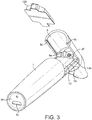
- the lid section 309 is slidably connected to the heater support section 307 so that it can be slid between a closed position shown in Figure 7 , in which the heater 313 is enclosed in the apparatus 300 and an open position shown in Figures 8 and 9 in which the heater 313 is exposed and in which a cartridge 400 can be inserted into the apparatus 300, as will be described in more detail below.
- the apparatus 300 may further comprise one or more air inlets 308, which in this example, are formed through the section 307 and which is/are in fluid communication with the outlet 311a of the mouthpiece 311.
- the apparatus 300 and its various sections may comprise any of the materials described above with respect to the first example.
- a heater 313 is in the form of a thin elongate plate comprising a pair of opposite first and second heating surfaces 313a or faces (only one of which is visible in the Figures).
- the heater 313 is arranged with its longitudinal axis parallel with that of the apparatus 300 and is supported in the heater support section 307 upright along one of its long edges so that both of the opposite first and second heating surfaces or faces 313a are exposed in the heater support section 307.
- each of the first and second heating surfaces 313a may also be curved, for example concave or convex in shape and may have formed thereon, e.g. printed, a respective resistive heating element, for example circuitry (not shown).
- the apparatus 300 further has an electronics/power chamber, within the main housing section 305, which in this example contains a power source 319 and electrical control circuitry 321.
- the electrical control circuitry 321 may include a controller, such as a microprocessor arrangement, configured and arranged to control the heater 313 as discussed further below.
- the power source 319 may be any of the power sources described above in respect of the apparatus 1. Again, the power source 319 is electrically coupled to the heater 313 to supply electrical power when required and under control of the electrical control circuitry 321 to heat the aerosol generating material in the cartridge 400 (as discussed, to volatize the aerosol generating material without causing the aerosol generating material to combust or undergo pyrolysis). Again, the apparatus 300 further comprises a charging slot 305c, which in this example, is formed through the first end 305a of the main housing section 305 to allow a charger (not shown) to be electrically connected to the power source 319 if the power source 319 is a rechargeable battery or to connect an external device (e.g. a computer) to the control circuitry 321 to download data from the control circuitry or upload data or software to the control circuitry 321.
- a charging slot 305c which in this example, is formed through the first end 305a of the main housing section 305 to allow a charger (not shown) to be electrical
- the apparatus 300 may further comprise any of the actuators and/or sensors as described above with respect to the apparatus 1 operably coupled to the control circuitry 321.
- the cartridge 400 is a dual-body arrangement comprising a first cartridge body 400a and a second cartridge body 400b.
- Each of the first cartridge body 400a and the second cartridge body 400b comprises a respective protective cover 402, 402' attached to, for example adhered to a respective planar base 404, 404'.
- Each cover 402, 402' and the planar base 404, 404' it is attached to together define a chamber for containing the aerosol generating material (not shown).
- the planar base 404 is substantially parallel to the longitudinal axis of the first cartridge body 400a and the planar base 404' is substantially parallel to the longitudinal axis of the second cartridge body 400b.
- each planar base 404, 404' is substantially rectangular in shape although other shapes are possible.
- Each protective cover 402, 402' comprises a main elongate central section 402a, 402a' and smaller first 402b, 402b' and second 402c, 402'c end sections at respective ends of the main elongate central section 402a, 402a'.
- the second 402c, 402'c end sections are offset with respect to each other about the longitudinal axis of the cartridge 400.
- Each central cover section 402a, 402a' defines an elongate recess 403, 403' along its upper surface.
- planar bases 404, 404' are connected together at opposing ends along a first line of weakening 408 and the first 402b, 402b' end sections are also connected together at opposing ends along a second line of weakening 410 that is aligned with the first line of weakening 408.
- the lines of weakening may be for example a perforated line, a serrated line or a cut line.
- the planar bases 404, 404' are formed of a sheet thermally conductive material, for example, metal foil such as aluminium foil, and the protective covers 402, 402' may be formed any of the materials described above with respect to the first example and adhered to the planar bases 404, 404' using a suitable adhesive as also described above with respect to the first example.
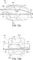
- a user takes a cartridge 400 in a 'prior to use' configuration shown in Figure 10a and folds the planar bases 404, 404' towards one another about the first weakening line 408.
- the folding causes the first cartridge body 400a and the second cartridge body 400b to separate from one another about the second weakening line 410 exposing the interior of the first cartridge body 400a through the aperture 402e and exposing the interior of the second cartridge body 400b through the aperture 402e', as best shown in Figure 10b .
- the aperture 402e provides an outlet for the first cartridge body 400a and the aperture 402e' provides an outlet for the second cartridge body 400b.
- the user may then arrange the cartridge 400 in the interior of the heater support section 307 with the heater 313 between the planar bases 404, 404' and continue to fold the planar bases 404, 404' together until the heater 313 is sandwiched between them.
- the heater 313 is sandwiched between them.
- at least a major portion or all of the bottom surface of the planar base 404 is against the first heating surface 313a of the heater 313 and at least a major portion or all of the bottom surface of the planar base 404' is against the second heating surface of the heater 313.
- Each of the first cartridge body 400a and the second cartridge body 400b comprises a respective member 412, 412', which in this example is in the form of a short tube that is open at both of its ends and extends through a planar base 404, 404' defining a passage through that planar base 404, 404' from one side to the other.
- Each member 412, 412' is located outside of a cover 402, 402' but directly adjacent to a central section 402a, 402a' and a second end section 402, 402'.
- Each member 412, 412' protrudes away from the underside of the planar base 404, 404' that it extends through.
- the ends of the members 412, 412' that puncture through the planar bases 404, 404' are preferably sharpened or pointed or the like in order to facilitate this puncturing.
- the member 412 acts as an inlet for the second cartridge body 400b and the member 412' acts as an inlet for the first cartridge body 400a.
- the heater support section 307 is generally 'U' shaped in cross section and comprises a first pair of parallel ridges 307a that run along its base and which define between them a first longitudinal slot 307b.
- the pair of parallel ridges 307b terminate in a raised cross piece 307c that straddles the parallel ridges 307a and which defines a second slot 307d that runs into the first longitudinal slot 307a such that the first 307a and second 307d slots meet at an angle of about 90 degrees.
- the heater 313 is supported in the second slot 307d and sits with an edge running parallel to and just above the first longitudinal slot 307b.
- respective first opposing sections (labelled 'A') of the planar bases 404, 404' are received in the first longitudinal slot 307b and each of the main elongate central cover sections 402a, 402a' are supported on a respective one of the parallel ridges 307a.
- Each of the parallel longitudinal edges 307e of the heater support section 307 defines a respective guide rail which extends slightly inwardly of the heater support section 307 and is used to slidably support the lid section 309.
- the lid section 309 is also substantially 'U' shaped in cross section.
- the lid section 309 defines a pair of parallel longitudinal slots 309a arranged at corresponding positions on opposite sides of the exterior surface of the lid section 309.
- the lid section 309 is slidably mounted on the heater support section 307 by means of each of the guide rails 307e of the heater support section 307 being received in a respective one of the parallel longitudinal slots 309a of the lid section 309.
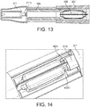
- lid section 309 This enables the lid section 309 to be slid between the open position shown in Figures 8, 9 and 13 in which a cartridge 400 can be inserted into or removed from the apparatus 300 and the closed position shown in Figure 7 in which, if inserted, a cartridge 400 is enclosed in the apparatus 400.
- the lid section 309 on its internal surface, defines a second longitudinal slot 309b which is parallel to and opposite the first longitudinal slot 307b in the heater support section 307.
- the second longitudinal slot 309b receives respective second opposing sections (labelled 'B') of the planar bases 404, 404', as is illustrated in Figure 12 .
- the lid section further defines, on its internal surface, a second pair 309c of parallel and opposing ridges.
- each of the second pair of ridges 309c is received in a respective recess 403, 403' defined in the main elongate central section 402a, 402a' of a protective cover 402, 402' of a respective one of the first 402a, 402b and second cartridge bodies.
- the mouthpiece 311 comprise a gasket 311b that has a generally circular cross section, which is located at the end of the mouthpiece 311 which connects to the lid section 309.
- the gasket 311b when the lid section 309 is moved into the closed position, engages the open end sections 402b, 402b' of the protective covers 402, 402'.
- the gasket 311b is in fluid communication with the outlet 311a of the mouthpiece 311.
- the control circuitry 321 is operated so that electrical current flows through the resistive heating elements (not shown) formed on the first 313a and second heating surfaces to cause the heater 313 to heat up so that the first heater surface 313a heats the aerosol generating material in the first cartridge body 400a and the second heater surface heats the aerosol generating material in the second cartridge body 400b.
- the planar bases 404, 404' are formed of a thermally conductive material and are in good thermal contact with the heater 313, heat is very efficiently transferred to the aerosol generating material in each cartridge body 400a, 400b. This causes at least one component of the aerosol generating material in each cartridge body 400a, 400b to volatilise without combusting the aerosol generating material.
- each cartridge body 400a, 400b When the user draws on the mouthpiece 311, this causes a reduction in pressure in each cartridge body 400a, 400b, which causes air to be drawn into each cartridge body 400a, 400b via the air inlet 308 of the section 307 and the respective air inlets defined by the members 412' and 412.
- this airflow causes the volatilised component(s) of the aerosol generating material to be cooled, so that it/they condense to form an aerosol either inside each cartridge body 400a, 400b, inside the mouthpiece 311 or inside both.
- the user's continued drawing causes the airflow and aerosol to be drawn into the user's mouth via the mouthpiece 311. This can be repeated until the volatile component(s) is/are exhausted.
- the airflow and volatilised component(s) of the aerosol generating material and/or aerosol exit the cartridge bodies 400a, 400b through the apertures 402e, 402e'.
- the user opens the lid section 309, removes the cartridge 400 and inserts another unspent cartridge 400 into the channel and repeats the above process.
- the resistive heating elements (not shown) formed on the first 313a and second heating surfaces can be controlled independently of each other so that the aerosol generating material in each cartridge body 400a, 400b can be heated independently of each other in different time intervals.
- the aerosol generating material may be different in each cartridge body 400a, 400b.
- one of the cartridge bodies 400a, 400b may comprise a flavoured material (e.g.
- the control circuitry 321 only activates the resistive heating element (not shown) on the one of the first and second heating surfaces contacting the planar base 404, 404' of the particular cartridge body 400a, 400b containing the flavoured material at times when the user would like to taste the flavour.
- the heater 313 may comprises a heat insulating layer (not shown) between, e.g. midway between, the first 313a and second heating surfaces to inhibit heat generated by an activated one of the resistive heating elements (not shown) being transferred through the body of the heater 313 to the heating surface on which the other non-activated one of the resistive heating elements is provided.
- a cartridge 400 may be provided in a pack (not shown) of such cartridges with any side of any given planar base being connected to any side of any other given planar base by a line of weakening to enable a cartridge to be separated (i.e. broken away from) by a user from the pack of cartridges.
- the first cartridge body 400a and the second cartridge body 400b are essentially mirror images of each other and so the second 402c, 402'c end sections are not offset with respect to each other about the longitudinal axis of the cartridge 400 but instead the second 402c, 402'c end sections are aligned and the respective members 412, 412' are aligned (e.g. the positions of the first end section 402c and the member 412 are reversed so that they mirror the positions of the of the first end section 402'c and the member 412' respectively).
- a cartridge 400 in a pack of such cartridges may be broken away from the pack by pivoting long sides of the bases 404, 404' about lines of weakening connecting those long sides of the bases 404, 404' to corresponding long sides of the bases of another such cartridge in the pack.
- the member 412 will puncture through the first planar base of the first cartridge body of the other such cartridge remaining on the pack in a region beneath the second end section of the cover of the first cartridge body of that other such cartridge and likewise the corresponding member of the first cartridge body of that other such cartridge will puncture through the first planar base 404 of the first cartridge body 400a in a region beneath the second end section 402c of the cover 402.
- the member 412' will puncture through the second planar base of the second cartridge body of the other such cartridge remaining on the pack in a region beneath the second end section of the cover of the second cartridge body of that cartridge and likewise the corresponding member of the second cartridge body of the other such cartridge will puncture through the second planar base 404' of the second cartridge body 400a' in a region beneath the second end section 402c' of the cover 402'.
- a user may then fold the planar bases 404, 404' towards one another about the first weakening line 408 to cause the first cartridge body 400a and the second cartridge body 400b to separate from one another about the second weakening line 410 similarly as discussed above with respect to Figures 10a and 10b .
- FIG. 15 to 19b there is shown a third example of an apparatus 500 and a cartridge 600 that is insertable within the apparatus 500.
- the apparatus 500 is similar to the apparatuses 1 and 300 described above and is another "tobacco-heating-product" apparatus arranged to heat aerosol generating material (not shown) contained within the cartridge 600 when the cartridge 600 is inserted inside the apparatus 500 to volatilise at least one component of the aerosol generating material.
- the apparatus 500 in this third example is again generally elongate and comprises a generally tubular housing 503.
- the tubular housing 503 comprises a main housing section 505, a heater support section 507 that supports a heater 513, a lid section 509 and a mouth piece 511.
- the main housing section 505 is very similar to the main housing sections of the two examples described above, and comprises a first longitudinal end 505a (which again defines a distal end of the whole of the apparatus 500) and a second longitudinal end 505b located at approximately just over half of the way along the length of the apparatus 500.
- the heater support section 507 extends from the second 505b longitudinal end of the main housing section 505 and defines a platform that supports a heater 513.
- the heater support section 507 may, as is the case in this example, comprise a plurality 507b, 507c of interconnected sections, one of which 507b is connected to the main housing section 505, or the heater support section 507 may be a single piece section.
- the apparatus 500 further comprises one or more air inlets 508, which in this example, are formed through the through the section 507c and which are in fluid communication with an outlet 511a of the mouthpiece 511.
- the heater support section 507 and the lid section 509 are connected by a hinge arrangement that is arranged to enable the lid section 509 to pivot with respect to the heater support section 507, between a closed position shown in Figures 15 and 16 and an open position shown in Figure 17 .
- the lid section 509 may, as is the case in this example, comprise a plurality 509d, 509e of interconnected sections, one of which 509e is connected to the mouthpiece 511, or the lid section 509 may be a single piece section.
- a heater 513 is similar to the heater in the second example, in that it is in the form of a thin elongate plate comprising a pair of opposite first and second heating surfaces 513a or faces (only one of which is visible) and is arranged with its longitudinal axis parallel with that of the apparatus 500 and is supported in the heater support section 507 upright along one of its long edges so that both of the opposite surfaces or faces 513a are exposed in the heater support section 507.
- each of the first and second heating surfaces 513a may also be curved, for example concave or convex in shape and may have formed thereon, e.g. printed, a respective resistive heating element, for example circuitry (not shown).
- an electronics/power chamber is provided within the main housing 505 containing a power source 519 (which may be any of the power sources described above) and electrical control circuitry 521 (which may comprise any of the control circuitry components described above) configured and arranged to control the heater 513.
- the apparatus 500 further comprises a charging slot 505b, which in this example, is formed through the first end 505a of the main housing section 505 to allow a charger (not shown) to be electrically connected to the power source 519 if the power source 519 is a rechargeable battery or to connect an external device (e.g. a computer) to the control circuitry 521 to download data from the control circuitry or upload data or software to the control circuitry 521.
- the apparatus 500 may further comprise any of the actuators and/or sensors as described above with respect to the apparatus operably coupled to the control circuitry 515.
- the cartridge 600 is a dual-body arrangement comprising a first cartridge body 600a and a second cartridge body 600b.
- Each of the first cartridge body 600a and the second cartridge body 600b comprises a respective protective cover 602, 602' attached to, for example adhered to, to a respective planar base 604, 604'.
- Each cover 602, 602' and the planar base 604, 604' to which it is attached together define a chamber for containing the aerosol generating material (not shown).
- the planar base 604 is substantially parallel to the longitudinal axis of the first cartridge body 600a and the planar base 604' is substantially parallel to the longitudinal axis of the second cartridge body 600b.
- Each planar base 604, 604' is substantially rectangular in shape.
- Each protective cover 602, 602' comprises a main elongate central section 602a, 602a' and smaller first 602b and second 602c end sections at respective ends of the main elongate central section 602a, 602a".
- the planar bases 604, 604' are formed of a sheet of thermally conductive material, for example, metal foil such as aluminium foil, and the protective covers 602, 602' may be formed any of the materials described above with respect to the first and second examples and adhered to the planar bases 604, 604' using a suitable adhesive as also described above with respect to the first and second examples.
- planar bases 604, 604' are joined in a 'side-to-side' relationship by being connected together at sides parallel to the longitudinal axis of the cartridge 600 along a line of weakening 608.
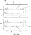
- a user takes a cartridge 600 in the 'prior to use' configuration shown in Figure 18a and folds the planar bases 604, 604' towards one another about the weakening line 608 until the planar bases 604, 604' are orientated in a position similar to that shown in Figure 18b .
- the user may then arrange the cartridge 600 in the interior of the heater support section 607 with the heater 513 between the planar bases 604, 604' and continue to fold the planar bases 604, 604' together until the heater 513 is sandwiched between them.
- at least a major portion or all of the bottom surface of the planar base 604 is against the first surface 513a of the heater513 and at least a major portion or all of the bottom surface of the planar base 604' is against the second surface of the heater513.
- Each of the first cartridge body 600a and the second cartridge body 600b comprises a respective member 612, 612', which in this example is in the form of a short tube that is open at both of its end and extends through a planar base 604, 604' defining a passage through that planar base 604, 604' from one side to the other.
- Each member 612, 612' is located outside of a cover 602, 602' but directly adjacent to a central section 602a, 602a' and a second end section 602, 602'.
- Each member 612, 612' protrudes away from the underside of the planar base 604, 604' that it extends through.
- the member 612' punctures through the planar base 604 of the first cartridge body 600a in a region beneath the second 602c end section of the cover 602 of the first cartridge body 600a.
- the member 612 punctures through the planar base 604' of the second cartridge body 600b in a region beneath the second 602c' end section of the cover 602' of the second cartridge body 600b'.
- the ends of the members 612, 612' that puncture through the planar bases 604, 604' are preferably sharpened or pointed or the like in order to facilitate this puncturing.
- the member 612 acts as an inlet for the second cartridge body 600b and the member 612' acts as an inlet for the first cartridge body 600a.
- the first cover end sections 602b, 602b' have respective open ends 602e, 602e' that act as respective outlets for the first cartridge body 600a and the second cartridge body 600b. These open ends 602e, 602e' may be provided with a protective layer (not shown), to keep the material inside fresh, and which is peeled away by a user prior to inserting the cartridge 600 in the apparatus 500.
- first cover end sections 602b, 602b' may be provided with lines of weakening (as described above with respect to the cartridge 400) and be connected to corresponding first cover end sections (not shown) of corresponding first and second cartridge bodies (not shown) of a corresponding dual body cartridge (not shown) in a pack of such dual body cartridges.
- the dual body cartridge 600 may be broken free, by a user, from such pack, prior to be being inserted into the apparatus 500. It will be appreciated that in such a pack, any side of any given planar base may be connected to any side of any other given planar base by a line of weakening to enable a cartridge to be separated by a user from the pack.
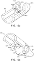
- the heater support section 507 is generally 'U' shaped in cross section and comprises a pair of opposing lobes 507a extending from opposite sides of one end 507b of the heater support section 507 parallel to its longitudinal axis.
- Each of the pair of lobes 507a defines a respective one of a pair of opposing recesses 507c (only one is visible in Figure 19a ).
- the recesses 507c have a generally circular cross section.
- the one end 507b also defines a first half 507d of a gasket for receiving the open ends 602e, 602e' of the cartridge 600.
- the lid section 509 is also substantially 'U' shaped in cross section.
- the lid section 509 and the mouthpiece 511 are both mounted on a joint 512 that enables the lid section 509 and mouthpiece 511 to be pivoted with respect to the heater support section 507 between the open and closed positions.
- the joint 512 comprises a part spherical body 512a that has a pair of circular end faces 512b (only one of which is visible in Figure 19b ).
- Each end face 512b has a respective lug 512c, which in this example is cylindrical in shape, extending therefrom.
- Each lug 512c is received in a respective one of the recesses 507c so that the joint 512 is supported between the opposing lobes 507a of the heater support section 507 and can rotate about an axis that is transverse to the longitudinal axis of the apparatus 500 to enable the lid section 509 and mouthpiece 511 to be pivoted between the open and closed positions.
- One end 509b of the lid section defines a second half 509d of the gasket for receiving the open ends 602e, 602e' the cartridge 600.
- Each of the halves 507d, 509d of the gasket is semi-circular in cross-section such that the gasket is circular in cross section when the two halves 507d, 509d are brought together (i.e. when that apparatus 600 is in the closed configuration).
- the gasket In the closed configuration, the gasket is aligned with an aperture 512d that is formed all of the way through the joint 512. Accordingly, the gasket is in fluid communication with the outlet 611a of the mouthpiece 611.
- the control circuitry 521 is operated so that electrical current flows through the resistive heating elements (not shown) formed on the first and second heating surfaces 513a to cause the heater 513 to heat up so that the first heater surface 513a heats the aerosol generating material in the first cartridge body 600a and the second heater surface heats the aerosol generating material in the second cartridge body 600b.
- the planar bases 604, 604' are formed of a thermally conductive material and are in good thermal contact with the heater 513, heat is very efficiently transferred to the aerosol generating material in each cartridge body 600a, 600b. This causes at least one component of the aerosol generating material in each cartridge body 600a, 600b to volatilise without combusting the aerosol generating material.
- each cartridge body 600a, 600b When the user draws on the mouthpiece 611, this causes a reduction in pressure in each cartridge body 600a, 600b, which causes air to be drawn into each cartridge body 600a, 600b via the air inlet 508 of the section 507b and the respective air inlets defined by the members 612' and 612.
- this air flow causes the volatilised component(s) of the aerosol generating material to be cooled, so that it/they condense to form an aerosol either inside each cartridge body 600a, 600b, inside the mouthpiece 511 or inside both.
- the user's continued drawing causes the airflow and aerosol to be drawn into the user's mouth via the mouthpiece 511. This can be repeated until the volatile component(s) is/are exhausted.
- the user opens the lid section 509, removes the cartridge 600 and inserts another unspent cartridge 600 into the channel and repeats the above process.
- the resistive heating elements (not shown) formed on the first and second heating surfaces 513a may be controlled independently of each other so that the aerosol generating material in each cartridge body 600a, 600b can be heated independently of each other in different time intervals.
- the aerosol generating material may be different in each cartridge body 600a, 600b, for example, one cartridge may contain a flavoured material.
- the heater 513 may comprises a heat insulating layer (not shown) to inhibit heat being transferred from one side of the heating 513 to the other.
- the heat conducting material of any of the above examples is a non-porous material, such as aluminium. Providing a non-porous material as the heat-conducting material means that the heater and the housing holding the heater stays clean, as upon heating, the aerosol produced does not pass to the heater and create a build-up of material.
- the planar base and/or the protective cover of any of the examples above is provided with one or more score lines and/or embossments, for example, at the position in which the protrusions are configured to pierce the planar base and/or protective cover.
- the score lines and/or embossments act to reduce the strength of the planar base and/or the protective cover the piercing location such that less force is required to pierce them.
- any of the protrusions discussed in the examples above may include a gasket to provide a seal to the pierced area.
- the aerosol generating material may be in the form of an aerosol generating material, for example a gel, that is a layer on, for example adhered to, the inner surface of the or each planar base of a cartridge. Furthermore, at least a portion of the inner surface of each planar base on which the aerosol generating material is received may be roughened. Surprisingly, it has been observed that having a rough surface on which the aerosol generating material is on may help prevent the aerosol generating material separating (e.g. de-laminating) from that surface during heating which would reduce the effectiveness of the heating process.
- Figures 20A and 20B show an example of a first inner surface 706 of the first sheet of heat conducting material 702 of a first base, in which the first inner surface is rough to provide an uneven or irregular surface.
- the aerosol forming material (not shown) will be located on the first inner surface 706 of the first sheet of heat conducting material 702.
- the first inner surface 706 is rough due to the fact that there are a plurality of protuberances 708.
- the first surface 206 is made rough by making a number of holes in the support layer 202. The holes may be made by penetrating the first surface 206 with a pin.
- the protuberances take the form of cylinders, however, any shape that projects from the first inner surface of the heat conducting material may be used, such as cubes, pyramids and irregular shapes. It is not necessary for the protuberances 708 to be formed of the same shape.
- the protuberance 708 in Figures 20A and 20B are shown as covering most of the first surface 706 of the heat conducting material 702, but in other examples, the protuberances 708 only cover part of the first surface 706 of the heat conducting material 702.
- the protuberances 708 have a height of between 0.1mm and 0.2mm and a width of between 0.2mm and 0.4mm, and more preferably have a height of 0.15mm and a width of 0.3mm.
- the first surface 706 of the heat conducting material is embossed to create the surface roughness.
- the protuberances 708 may also be formed by embossing. Embossing the first inner surface 706 of the heat conducting material is a simple and repeatable way of creating a rough surface.
- the embossment may take the form of one or more logos.
- the first inner surface 706 may be made rough by including one or more ridges, folds, indents and raised sections.
- the first inner surface 706 may be embossed using various patterns, such as one or more of spirals, lines; and/or squares.
- the rough first inner surface 706 of the heat conducting material 702 acts to increase the contact surface area between the aerosol generating material 704 and the heat conducting material 702.
- An example of article 700 formed from the heat conducting material 702 with a rough first inner surface 706 and aerosol generating material 704 is shown in Figure 20C .
- the increased surface area will increase the adhesion between the aerosol forming material 704 and the heat conducting material 702, and hence reduce the likelihood of the aerosol generating material 704 separating from the first inner surface 706 of the heat conducting material 702.
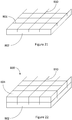
- the first inner surface 806 of the heat conducting material 802 is made rough by having one or more score lines 810 formed in the first inner surface 806.
- Figure 21 shows the heat conducting material 802 with six score lines 810 applied to the first inner surface 806, however, in some examples there are fewer than six score lines and in other examples there are more than six score lines 810 applied to the first inner surface 806.
- score lines 810 perform the function of adding a surface roughness to the first surface of the heat conducting material 806, which increases the adhesion between the aerosol generating material 804 and the layer 802.
- the surface roughness of the first inner surface 806 of the heat conducting material is provided by the score lines 810.
- the surface roughness of the first inner surface 806 of the heat conducting material is provided by a combination of the perturbations 708 and the score lines 810.
- the score lines 810 may also be applied to the aerosol generating material 804. Applying score lines 810 to the aerosol generating material 804 results in the aerosol generating material 804 being pooled into one or more separate sections delineated by the score lines 810. Separating the aerosol generating material 804 into separate sections provides more flow paths for any volatilised components and the outer surface of the aerosol generating material 804.
- the gel 704 and 804 may be formed from different tobacco extracts, such as Burley, Virgina and Oriental. Aerosol generating gels 704, 804 formed from different tobacco extracts may have different properties, for example, gels formed from Burley tobacco is more brittle, whereas gels formed from Virginia and Oriental is more pliable.
- Embodiments of the invention are configured to comply with applicable laws and/or regulations, such as, by way of non-limiting example, regulations relating to flavours, additives, emissions, constituents, and/or the like.
- the invention may be configured such that a device implementing the invention is compliant with applicable regulations before and after adjustment by a user.
- Such implementations may be configured to be compliant with applicable regulations in all user-selectable positions.
- the configuration is such that a device implementing the invention meets or exceeds required regulatory test(s) in all user-selectable positions, such as, by way of non-limiting example, the testing threshold(s)/ceiling(s) for emissions and/or smoke constituents.
Landscapes
- Health & Medical Sciences (AREA)
- Engineering & Computer Science (AREA)
- Anesthesiology (AREA)
- Biomedical Technology (AREA)
- Heart & Thoracic Surgery (AREA)
- Hematology (AREA)
- Life Sciences & Earth Sciences (AREA)
- Animal Behavior & Ethology (AREA)
- General Health & Medical Sciences (AREA)
- Public Health (AREA)
- Veterinary Medicine (AREA)
- Bioinformatics & Cheminformatics (AREA)
- Pulmonology (AREA)
- Disinfection, Sterilisation Or Deodorisation Of Air (AREA)
Claims (15)
- Patrone (400; 600) zur Verwendung mit einer Vorrichtung (300; 500) zum Erhitzen von aerosolerzeugendem Material, um mindestens eine Komponente des aerosolerzeugenden Materials zu verflüchtigen, wobei die Patrone umfasst:einen ersten Körper (400a; 600a), der eine erste Kammer definiert, wobei der erste Körper eine erste Basis (404; 604) umfasst, die eine Platte aus wärmeleitendem Material umfasst und eine erste Außenfläche aufweist; undaerosolerzeugendes Material, das sich in der ersten Kammer befindet; undwobei mindestens ein größerer Abschnitt der ersten Außenfläche der ersten Basis dazu eingerichtet ist, eine erste Heizfläche (313a; 512a) einer Heizvorrichtung (313; 513) der Vorrichtung zum Erhitzen des aerosolerzeugenden Materials innerhalb der ersten Kammer zu berühren, und wobei die erste Basis im Wesentlichen parallel zu einer Längsachse des ersten Körpers liegt;dadurch gekennzeichnet, dass
die Patrone ferner umfassteinen zweiten Körper (400b; 600b), der eine zweite Kammer definiert, wobei der zweite Körper eine zweite Basis (404'; 604') umfasst, die eine Platte aus wärmeleitendem Material umfasst und eine zweite Außenfläche aufweist; undaerosolerzeugendes Material, das sich in der zweiten Kammer befindet; undwobei mindestens ein größerer Abschnitt der zweiten Außenfläche der zweiten Basis dazu eingerichtet ist, mit einer zweiten Heizfläche (313a; 513a) der Heizvorrichtung der Vorrichtung in Kontakt zu kommen, und wobei die zweite Basis im wesentlichen parallel zu einer Längsachse des zweiten Körpers liegt. - Patrone nach Anspruch 1, wobei der erste Körper eine erste Abdeckung (402; 602) umfasst, die an der ersten Basis befestigt ist, wobei die erste Abdeckung und die erste Basis die erste Kammer definieren, und wobei die erste Abdeckung einen ersten Abschnitt und einen zweiten Abschnitt an einem Ende des ersten Abschnitts umfasst, wobei der erste Abschnitt breiter als der zweite Abschnitt ist.
- Patrone nach einem der vorhergehenden Ansprüche, wobei die erste Basis und die zweite Basis miteinander verbunden sind, um eine relative Schwenkbewegung der ersten Basis und der zweiten Basis zu ermöglichen, sodass ein Benutzer die erste Außenfläche in Kontakt mit der ersten Heizfläche der Heizvorrichtung und die zweite Außenfläche in Kontakt mit der zweiten Heizfläche der Heizvorrichtung bringen kann.
- Patrone nach Anspruch 3, wobei die erste Basis und die zweite Basis entlang einer ersten Schwächungslinie (408; 608) verbunden sind, um die relative Schwenkbewegung zu ermöglichen.
- Patrone nach einem der Ansprüche 3 oder 4, wobei die erste Basis und die zweite Basis in einer Vor-Gebrauch-Ausbildung an entsprechenden Seiten der ersten Basis und der zweiten Basis, die im Wesentlichen rechtwinklig zu einer Längsachse der Patrone liegen, verbunden sind.
- Patrone nach Anspruch 5, wobei der zweite Körper eine zweite Abdeckung (402') umfasst, die an der zweiten Basis befestigt ist, wobei die zweite Abdeckung und die zweite Basis die zweite Kammer definieren und wobei die erste Abdeckung und die zweite Abdeckung in der Vor-Gebrauch-Ausbildung entlang einer zweiten Schwächungslinie verbunden sind, die reißt, wenn die erste Basis und die zweite Basis eine relative Schwenkbewegung erfahren, wodurch die erste Abdeckung und die zweite Abdeckung getrennt werden, um einen Auslass für verflüchtigtes Material und/oder Aerosol für die erste Abdeckung und einen Auslass für verflüchtigtes Material und/oder Aerosol für die zweite Abdeckung bereitzustellen.
- Patrone nach Anspruch 6, wobei die erste Basis einen ersten Durchstecher (412) und die zweite Basis einen zweiten Durchstecher (412') umfasst.
- Patrone nach Anspruch 7, wobei der erste Durchstecher zum Durchstechen der zweiten Basis dient, um einen Lufteinlass für die zweite Kammer bereitzustellen, und der zweite Durchstecher zum Durchstechen der ersten Basis dient, um einen Lufteinlass für die erste Kammer bereitzustellen.
- Patrone nach Anspruch 8, wobei die erste Abdeckung einen ersten Abschnitt (402a) und einen zweiten Abschnitt (402c) an einem Ende des ersten Abschnitts umfasst, wobei der erste Abschnitt breiter als der zweite Abschnitt ist, wobei der zweite Durchstecher auf der zweiten Basis so positioniert ist, dass er die erste Basis an einer Stelle durchstößt, die durch den zweiten Abschnitt der ersten Abdeckung abgedeckt ist.
- Patrone nach Anspruch 8 oder 9, wobei die zweite Abdeckung einen ersten Abschnitt (402a') und einen zweiten Abschnitt (402c') an einem Ende des ersten Abschnitts umfasst, wobei der erste Abschnitt breiter als der zweite Abschnitt ist, wobei der erste Durchstecher auf der ersten Basis so positioniert ist, dass er die zweite Basis an einer Stelle durchstößt, die durch den zweiten Abschnitt der zweiten Abdeckung abgedeckt ist.
- Patrone nach einem der Ansprüche 3 oder 4, wobei die erste Basis und die zweite Basis in einer Vor-Gebrauch-Ausbildung an entsprechenden Seiten der ersten Basis und der zweiten Basis, die im Wesentlichen parallel zu einer Längsachse der Patrone liegen, verbunden sind.
- Patrone nach Anspruch 11, wobei der zweite Körper eine zweite Abdeckung (602') umfasst, die an der zweiten Basis befestigt ist, wobei die zweite Abdeckung und die zweite Basis die zweite Kammer definieren, wobei die erste Basis einen ersten Durchstecher (612) und die zweite Basis einen zweiten Durchstecher (612') umfasst.
- Patrone nach Anspruch 12, wobei die erste Abdeckung einen ersten Abschnitt (602a) und einen zweiten Abschnitt (602c) an einem Ende des ersten Abschnitts umfasst, wobei der erste Abschnitt breiter als der zweite Abschnitt ist, wobei der zweite Durchstecher auf der zweiten Basis so positioniert ist, dass er die erste Basis an einer Stelle durchstößt, die durch den zweiten Abschnitt der ersten Abdeckung abgedeckt ist.
- Vorrichtung (300; 500) zum Erhitzen von aerosolerzeugendem Material, um mindestens eine Komponente des aerosolerzeugenden Materials zu verflüchtigen, wobei die Vorrichtung umfasst:ein Gehäuse, das eine Heizvorrichtung (313; 513) umfasst, wobei die Heizvorrichtung mindestens eine erste Heizfläche (513a; 513a) umfasst, wobei die erste Heizfläche so ausgebildet ist, dass sie mindestens einen größeren Abschnitt einer wärmeleitenden Basis (404; 604) eines ersten Körpers (400a; 600a) einer Patrone (400; 600) berührt, die in das Gehäuse einführbar ist, und wobei sich die Heizvorrichtung im Wesentlichen parallel zu einer Längsachse der Vorrichtung erstreckt, wodurch die Heizvorrichtung im Gebrauch aerosolerzeugendes Material in einer durch den ersten Körper definierten Kammer erhitzt, um mindestens eine Komponente des aerosolerzeugenden Materials zu verflüchtigen;
dadurch gekennzeichnet, dass
die Vorrichtung ferner umfassteine zweite Heizfläche (313a; 513a), wobei die zweite Heizfläche zum Kontaktieren mindestens eines größeren Abschnitts der wärmeleitenden Basis (404'; 604') eines zweiten Körpers (400b; 600b) der Patrone dient, die in das Gehäuse einführbar ist, wobei die Heizvorrichtung im Gebrauch aerosolerzeugendes Material in einer durch den zweiten Körper definierten Kammer erhitzt, um mindestens eine Komponente des aerosolerzeugenden Materials zu verflüchtigen. - Vorrichtung nach Anspruch 14, wobei die Heizvorrichtung eine Heizplatte ist, die die erste Heizfläche und die zweite Heizfläche definiert, wobei die erste und die zweite Heizfläche gegenüberliegende Flächen der Heizplatte sind.
Priority Applications (2)
| Application Number | Priority Date | Filing Date | Title |
|---|---|---|---|
| PL17717339T PL3435798T3 (pl) | 2016-03-30 | 2017-03-30 | Urządzenie do podgrzewania materiału generującego aerozol i wkład do urządzenia |
| EP20169384.3A EP3725172B1 (de) | 2016-03-30 | 2017-03-30 | Vorrichtung zum erhitzen von aerosolerzeugendem material und patrone für die vorrichtung |
Applications Claiming Priority (2)
| Application Number | Priority Date | Filing Date | Title |
|---|---|---|---|
| GBGB1605357.1A GB201605357D0 (en) | 2016-03-30 | 2016-03-30 | Apparatus for heating aerosol generating material and a cartridge for the apparatus |
| PCT/EP2017/057630 WO2017167932A1 (en) | 2016-03-30 | 2017-03-30 | Apparatus for heating aerosol generating material and a cartridge for the apparatus |
Related Child Applications (1)
| Application Number | Title | Priority Date | Filing Date |
|---|---|---|---|
| EP20169384.3A Division EP3725172B1 (de) | 2016-03-30 | 2017-03-30 | Vorrichtung zum erhitzen von aerosolerzeugendem material und patrone für die vorrichtung |
Publications (2)
| Publication Number | Publication Date |
|---|---|
| EP3435798A1 EP3435798A1 (de) | 2019-02-06 |
| EP3435798B1 true EP3435798B1 (de) | 2020-04-29 |
Family
ID=56027603
Family Applications (2)
| Application Number | Title | Priority Date | Filing Date |
|---|---|---|---|
| EP20169384.3A Active EP3725172B1 (de) | 2016-03-30 | 2017-03-30 | Vorrichtung zum erhitzen von aerosolerzeugendem material und patrone für die vorrichtung |
| EP17717339.0A Active EP3435798B1 (de) | 2016-03-30 | 2017-03-30 | Vorrichtung zum erhitzen von aerosolerzeugendem material und patrone für die vorrichtung |
Family Applications Before (1)
| Application Number | Title | Priority Date | Filing Date |
|---|---|---|---|
| EP20169384.3A Active EP3725172B1 (de) | 2016-03-30 | 2017-03-30 | Vorrichtung zum erhitzen von aerosolerzeugendem material und patrone für die vorrichtung |
Country Status (12)
| Country | Link |
|---|---|
| US (2) | US11433191B2 (de) |
| EP (2) | EP3725172B1 (de) |
| JP (2) | JP6870892B2 (de) |
| CN (1) | CN109068733A (de) |
| CA (1) | CA3019243A1 (de) |
| ES (2) | ES2808002T3 (de) |
| GB (1) | GB201605357D0 (de) |
| LT (1) | LT3725172T (de) |
| PL (2) | PL3725172T3 (de) |
| PT (1) | PT3725172T (de) |
| RU (1) | RU2713476C1 (de) |
| WO (1) | WO2017167932A1 (de) |
Cited By (4)
| Publication number | Priority date | Publication date | Assignee | Title |
|---|---|---|---|---|
| US11730199B2 (en) | 2018-06-07 | 2023-08-22 | Juul Labs, Inc. | Cartridges for vaporizer devices |
| EP3490390B1 (de) * | 2016-07-29 | 2024-03-13 | Philip Morris Products S.A. | Aerosolerzeugungssystem mit einer kartusche mit einem gel |
| EP4295711A4 (de) * | 2021-02-17 | 2024-11-27 | Japan Tobacco Inc. | Heizeinheit für verbrennungsfreien heizgeschmacksinhalator und verbrennungsfreier heizgeschmacksinhalator |
| USD1095794S1 (en) | 2021-01-18 | 2025-09-30 | Altria Client Services Llc | Aerosol-generating capsule |
Families Citing this family (87)
| Publication number | Priority date | Publication date | Assignee | Title |
|---|---|---|---|---|
| PL3160552T3 (pl) | 2014-06-30 | 2020-03-31 | Syqe Medical Ltd. | Wkład z dawką leku dla urządzenia inhalacyjnego |
| US20170055574A1 (en) | 2015-08-31 | 2017-03-02 | British American Tobacco (Investments) Limited | Cartridge for use with apparatus for heating smokable material |
| US20180317554A1 (en) | 2015-10-30 | 2018-11-08 | British American Tobacco (Investments) Limited | Article for use with apparatus for heating smokable material |
| US20170119051A1 (en) | 2015-10-30 | 2017-05-04 | British American Tobacco (Investments) Limited | Article for Use with Apparatus for Heating Smokable Material |
| US20170119049A1 (en) | 2015-10-30 | 2017-05-04 | British American Tobacco (Investments) Limited | Article for Use with Apparatus for Heating Smokable Material |
| US20170119050A1 (en) | 2015-10-30 | 2017-05-04 | British American Tobacco (Investments) Limited | Article for Use with Apparatus for Heating Smokable Material |
| EP3851102B1 (de) | 2016-01-06 | 2025-04-16 | Syqe Medical Ltd. | Niedrigdosierte therapeutische behandlung |
| US12201767B2 (en) | 2016-04-22 | 2025-01-21 | Juul Labs, Inc. | Aerosol devices having compartmentalized materials |
| WO2018002085A1 (en) | 2016-06-29 | 2018-01-04 | British American Tobacco (Investments) Limited | Apparatus for heating smokable material |
| US12478096B2 (en) | 2016-06-29 | 2025-11-25 | Nicoventures Trading Limited | Apparatus for heating smokable material |
| JP6933323B2 (ja) | 2016-06-29 | 2021-09-08 | ニコベンチャーズ トレーディング リミテッド | 喫煙材を加熱するための装置 |
| US10791760B2 (en) | 2016-07-29 | 2020-10-06 | Altria Client Services Llc | Aerosol-generating system including a cartridge containing a gel |
| GB201615601D0 (en) * | 2016-09-14 | 2016-10-26 | British American Tobacco Investments Ltd | Receptacle section |
| GB201615602D0 (en) | 2016-09-14 | 2016-10-26 | British American Tobacco Investments Ltd | Receptacle Section |
| GB201615608D0 (en) | 2016-09-14 | 2016-10-26 | British American Tobacco Investments Ltd | A container |
| GB2556331A (en) | 2016-09-14 | 2018-05-30 | British American Tobacco Investments Ltd | A container |
| GB201615603D0 (en) | 2016-09-14 | 2016-10-26 | British American Tobacco Investments Ltd | Receptacle section |
| GB201700136D0 (en) | 2017-01-05 | 2017-02-22 | British American Tobacco Investments Ltd | Aerosol generating device and article |
| GB201700620D0 (en) | 2017-01-13 | 2017-03-01 | British American Tobacco Investments Ltd | Aerosol generating device and article |
| GB201705206D0 (en) | 2017-03-31 | 2017-05-17 | British American Tobacco Investments Ltd | Apparatus for a resonance circuit |
| GB201705152D0 (en) * | 2017-03-30 | 2017-05-17 | British American Tobacco Investments Ltd | An article for use with an apparatus for heating an aerosol generating agent |
| GB201705208D0 (en) * | 2017-03-31 | 2017-05-17 | British American Tobacco Investments Ltd | Temperature determination |
| AU2018334042B2 (en) | 2017-09-15 | 2022-01-06 | Nicoventures Trading Limited | Apparatus for heating smokable material |
| GB201716417D0 (en) * | 2017-10-06 | 2017-11-22 | Project Paradise Ltd | Inhalation device and substrate |
| GB201717484D0 (en) * | 2017-10-24 | 2017-12-06 | Nicoventures Holdings Ltd | Electronic aerosol provision device |
| GB201717486D0 (en) | 2017-10-24 | 2017-12-06 | Nicoventures Holdings Ltd | Mechanism for hatch of electronic aerosol provision device |
| GB201717479D0 (en) | 2017-10-24 | 2017-12-06 | Nicoventures Holdings Ltd | Hatch section for an electronic aerosol provision device |
| GB201717480D0 (en) | 2017-10-24 | 2017-12-06 | Nicoventures Holdings Ltd | Electronic aerosol provision device with seal |
| GB201717489D0 (en) * | 2017-10-24 | 2017-12-06 | Nicoventures Holdings Ltd | Electronic aerosol provision device |
| JP7206274B2 (ja) * | 2017-11-30 | 2023-01-17 | フィリップ・モーリス・プロダクツ・ソシエテ・アノニム | 内表面サセプタ材料を有するカートリッジ |
| GB201720338D0 (en) | 2017-12-06 | 2018-01-17 | British American Tobacco Investments Ltd | Component for an aerosol-generating apparatus |
| KR102761817B1 (ko) * | 2018-04-17 | 2025-02-03 | 필립모리스 프로덕츠 에스.에이. | 에어로졸 발생 시스템 |
| EA039744B1 (ru) | 2018-06-20 | 2022-03-05 | ДжейТи ИНТЕРНЕШНЛ СА | Устройство, генерирующее пар |
| CN108652086B (zh) * | 2018-07-11 | 2023-10-13 | 绿烟实业(深圳)有限公司 | 用于非燃烧烟具的烟盒及非燃烧烟具设备 |
| JP7399942B2 (ja) * | 2018-07-26 | 2023-12-18 | フィリップ・モーリス・プロダクツ・ソシエテ・アノニム | エアロゾルを発生させるための装置 |
| EP4694574A3 (de) | 2018-07-31 | 2026-03-25 | Juul Labs, Inc. | Kartuschenbasierter verdampfer mit nicht brennender wärme |
| GB2576712B (en) * | 2018-08-23 | 2022-06-01 | All Vape Ltd | A pod |
| US12048329B2 (en) * | 2018-09-14 | 2024-07-30 | Imperial Tobacco Limited | Consumable for a smoking substitute device |
| US12478112B2 (en) * | 2018-10-30 | 2025-11-25 | R.J. Reynolds Tobacco Company | Smoking article cartridge |
| IT201800010062A1 (it) * | 2018-11-06 | 2020-05-06 | Gd Spa | Dispositivo da fumo, kit da fumo e metodo di utilizzo di detto dispositivo |
| JP7502015B2 (ja) | 2018-11-08 | 2024-06-18 | ジュール・ラブズ・インコーポレイテッド | 1以上の加熱要素を備えた気化器デバイス |
| JP7292395B2 (ja) * | 2019-01-15 | 2023-06-16 | フィリップ・モーリス・プロダクツ・ソシエテ・アノニム | 閉鎖可能な空洞を有するエアロゾル発生装置 |
| WO2020154690A1 (en) | 2019-01-25 | 2020-07-30 | Juul Labs, Inc. | Vaporizer device and cartridge |
| JP7480159B2 (ja) * | 2019-02-08 | 2024-05-09 | サイケ メディカル リミテッド | 吸入装置における温度を制御するための装置および方法 |
| WO2020221674A1 (en) * | 2019-04-29 | 2020-11-05 | Philip Morris Products S.A. | Aerosol-generating device with movably attached mouthpiece |
| KR20250166353A (ko) * | 2019-05-06 | 2025-11-27 | 쥴 랩스, 인크. | 기화기 장치와 함께 사용하기 위한 인서트 |
| CN111588082A (zh) * | 2019-06-03 | 2020-08-28 | 深圳市艾维普思科技有限公司 | 电子烟的雾化装置及电子烟 |
| EP4585242A3 (de) | 2019-06-12 | 2025-08-20 | Juul Labs, Inc. | Aufdampfbarer materialeinsatz für verdampfervorrichtung |
| WO2021026443A1 (en) | 2019-08-08 | 2021-02-11 | Juul Labs, Inc. | Vaporizable material insert for vaporizer device |
| EP4025082A1 (de) * | 2019-09-06 | 2022-07-13 | JT International SA | Aerosolerzeugungsvorrichtung und heizkammer dafür |
| EP4674296A3 (de) | 2019-09-06 | 2026-03-18 | Juul Labs, Inc. | Kartuschenbasierter verdampfer mit nicht brennender wärme |
| US20230142595A1 (en) * | 2019-10-09 | 2023-05-11 | Jt International Sa | Aerosol Generation Device |
| EP4076058A1 (de) | 2019-12-17 | 2022-10-26 | Juul Labs, Inc. | Heizsystem für verdampfbaren materialeinsatz |
| KR102503841B1 (ko) * | 2019-12-19 | 2023-02-27 | 주식회사 케이티앤지 | 가열 요소를 포함하는 에어로졸 발생 장치 및 에어로졸 발생 시스템 |
| WO2021125561A1 (en) * | 2019-12-19 | 2021-06-24 | Kt&G Corporation | Aerosol generating device including heating element and aerosol generating system |
| US20230034238A1 (en) * | 2019-12-19 | 2023-02-02 | Jt International S.A. | Aerosol Generation Device |
| EP4114215A1 (de) * | 2020-03-04 | 2023-01-11 | JT International S.A. | Aerosolerzeugungsvorrichtung und zugehörige entfernbare kartusche und aerosolerzeugungsset |
| US11278688B2 (en) * | 2020-03-12 | 2022-03-22 | Max Azevedo | Inhaling device for heavy metal salts and a method of use thereof for medical treatment |
| WO2021233790A1 (en) * | 2020-05-22 | 2021-11-25 | Jt International Sa | Aerosol generating device |
| WO2021233794A1 (en) * | 2020-05-22 | 2021-11-25 | Jt International Sa | Aerosol generating device |
| GB202012177D0 (en) * | 2020-08-05 | 2020-09-16 | Nicoventures Trading Ltd | Aerosol provision device |
| WO2022070263A1 (ja) * | 2020-09-29 | 2022-04-07 | 日本たばこ産業株式会社 | 非燃焼式吸引器の電源ユニット、非燃焼式吸引器 |
| US11856986B2 (en) * | 2020-10-19 | 2024-01-02 | Rai Strategic Holdings, Inc. | Customizable panel for aerosol delivery device |
| EP4231863A1 (de) * | 2020-10-23 | 2023-08-30 | JT International SA | Dampferzeugungssystem |
| CN116568167A (zh) | 2020-12-07 | 2023-08-08 | 菲利普莫里斯生产公司 | 具有可移动上游盖和下游盖的气溶胶生成装置 |
| WO2022136151A1 (en) * | 2020-12-22 | 2022-06-30 | Philip Morris Products S.A. | Aerosol-generating device with cartridge insertion in a single orientation |
| WO2022134311A1 (zh) * | 2020-12-25 | 2022-06-30 | 云南中烟工业有限责任公司 | 一种手动定量添加烟油凝胶层的电子烟烟具套装及其使用方法 |
| US12053022B2 (en) * | 2021-01-04 | 2024-08-06 | Altria Client Services Llc | Capsules with integrated mouthpieces, heat-not-burn (HNB) aerosol-generating devices, and methods of generating an aerosol |
| US11910826B2 (en) | 2021-01-18 | 2024-02-27 | Altria Client Services Llc | Heat-not-burn (HNB) aerosol-generating devices and capsules |
| US12274295B2 (en) | 2021-01-18 | 2025-04-15 | Altria Client Services Llc | Heat-not-burn (HNB) aerosol-generating devices and capsules |
| WO2022175199A2 (en) * | 2021-02-19 | 2022-08-25 | Philip Morris Products S.A. | An aerosol-generating device having a movable housing portion |
| TW202235015A (zh) * | 2021-03-05 | 2022-09-16 | 瑞士商傑太日煙國際股份有限公司 | 用於包括固體氣溶膠產生基質的消耗品之加熱器 |
| JP2024511931A (ja) * | 2021-03-30 | 2024-03-18 | ジェイティー インターナショナル エスエイ | 櫛形電極を有するエアロゾル発生デバイス |
| CN115701332A (zh) * | 2021-08-02 | 2023-02-10 | 深圳市合元科技有限公司 | 气雾生成系统及气雾生成装置 |
| GB202111269D0 (en) * | 2021-08-04 | 2021-09-15 | Nicoventures Trading Ltd | A consumable for use with a non-combustible aerosol provisioin device |
| CA206074S (en) * | 2021-08-30 | 2023-03-28 | Blends Creative Inc | Oral vaporizer |
| US12127592B2 (en) | 2021-09-20 | 2024-10-29 | Altria Client Services Llc | Capsule validation for heat-not-burn (HNB) aerosol-generating devices |
| US20250261693A1 (en) * | 2021-10-27 | 2025-08-21 | Jt International Sa | Aerosol Generating Device Comprising a Supporting Structure Receiving Heating Plates |
| JP2025540532A (ja) * | 2022-12-15 | 2025-12-15 | フィリップ・モーリス・プロダクツ・ソシエテ・アノニム | 単一の誘導コイルを備えるハイブリッド式エアロゾル発生装置 |
| US20240277950A1 (en) * | 2023-02-20 | 2024-08-22 | Win Htay Fang | Reliable compact inhalation device for asthma and chronic obstructive pulmonary disease |
| WO2024236796A1 (ja) * | 2023-05-18 | 2024-11-21 | 日本たばこ産業株式会社 | 香味吸引器、消費材、及び香味吸引システム |
| WO2025016826A1 (en) * | 2023-07-18 | 2025-01-23 | Jt International Sa | A removeable cartridge for a vapour generating device |
| CN117158639A (zh) * | 2023-10-18 | 2023-12-05 | 湖北中烟工业有限责任公司 | 一种卷烟纸及其应用 |
| EP4609731A1 (de) * | 2024-02-28 | 2025-09-03 | JT International SA | Aerosolerzeugungssystem |
| WO2025202133A1 (en) * | 2024-03-26 | 2025-10-02 | Philip Morris Products S.A. | Aerosol-generating device with protrusions |
| WO2025202129A1 (en) * | 2024-03-26 | 2025-10-02 | Philip Morris Products S.A. | Aerosol-generating device with curved inner wall |
| WO2025202239A1 (en) * | 2024-03-26 | 2025-10-02 | Philip Morris Products S.A. | Aerosol-generating device comprising a connection mechanism |
Family Cites Families (28)
| Publication number | Priority date | Publication date | Assignee | Title |
|---|---|---|---|---|
| US5591368A (en) * | 1991-03-11 | 1997-01-07 | Philip Morris Incorporated | Heater for use in an electrical smoking system |
| US20080060663A1 (en) * | 2006-09-07 | 2008-03-13 | Bassam Hamade | Pre-sealed foil pouch containing such as flavored tobacco for use with a hookah pipe and head attachment assembly |
| US8991402B2 (en) * | 2007-12-18 | 2015-03-31 | Pax Labs, Inc. | Aerosol devices and methods for inhaling a substance and uses thereof |
| US20090293888A1 (en) * | 2008-05-30 | 2009-12-03 | Vapor For Life | Portable vaporizer for plant material |
| GB0813686D0 (en) * | 2008-07-25 | 2008-09-03 | Gamucci Ltd | A method and apparatus relating to electronic smoking-substitute devices |
| EP2340730A1 (de) * | 2009-12-30 | 2011-07-06 | Philip Morris Products S.A. | Geformtes Heizgerät für ein Aerosolerzeugungssystem |
| GB201001944D0 (en) * | 2010-02-05 | 2010-03-24 | Kind Consumer Ltd | A simulated smoking device |
| EA019736B1 (ru) * | 2010-12-01 | 2014-05-30 | Евгений Иванович Евсюков | Ингаляционное устройство |
| US9078473B2 (en) | 2011-08-09 | 2015-07-14 | R.J. Reynolds Tobacco Company | Smoking articles and use thereof for yielding inhalation materials |
| RU2608712C2 (ru) * | 2011-09-06 | 2017-01-23 | Бритиш Америкэн Тобэкко (Инвестментс) Лимитед | Изоляция |
| MY168355A (en) * | 2011-12-30 | 2018-10-31 | Philip Morris Products Sa | Aerosol generating device with improved temperature distribution |
| US8881737B2 (en) | 2012-09-04 | 2014-11-11 | R.J. Reynolds Tobacco Company | Electronic smoking article comprising one or more microheaters |
| DE202014011261U1 (de) | 2013-12-23 | 2018-11-13 | Juul Labs Uk Holdco Limited | Systeme für eine Verdampfungsvorrichtung |
| SG11201605380WA (en) * | 2013-12-31 | 2016-07-28 | Philip Morris Products Sa | An aerosol-generating device, and a capsule for use in an aerosol-generating device |
| EP3099363A4 (de) * | 2014-01-31 | 2018-03-28 | Cannakorp, Inc. | Verfahren und vorrichtung zur erzeugung von kräuterdampf |
| AU2014381785B2 (en) * | 2014-02-10 | 2019-03-14 | Philip Morris Products S.A. | Fluid permeable heater assembly for an aerosol-generating system and method for assembling a fluid permeable heater for an aerosol-generating system |
| UA121461C2 (uk) * | 2014-02-10 | 2020-06-10 | Філіп Морріс Продактс С.А. | Система, що генерує аерозоль, що містить пристрій і картридж, у якій пристрій забезпечує електричний контакт із картриджем |
| DE202014001718U1 (de) * | 2014-02-27 | 2015-05-28 | Xeo Holding GmbH | Rauchvorrichtung |
| CA3114677A1 (en) * | 2014-05-12 | 2015-11-19 | Loto Labs, Inc. | Improved vaporizer device |
| TWI669073B (zh) * | 2014-06-24 | 2019-08-21 | 瑞士商菲利浦莫里斯製品股份有限公司 | 氣溶膠產生系統、氣溶膠產生物件、氣溶膠產生裝置及控制反應化學計量的方法 |
| RU2690401C2 (ru) * | 2014-06-30 | 2019-06-03 | Сике Медикал Лтд. | Способ и устройство для испарения и ингаляции выделенных веществ |
| RS57811B1 (sr) * | 2014-07-11 | 2018-12-31 | Philip Morris Products Sa | Sistem za proizvodnju aerosola koji uključuje detekciju uloška |
| EP3166430B2 (de) * | 2014-07-11 | 2025-03-26 | Philip Morris Products S.A. | Aerosolbildungskartusche mit einem tabakhaltigen material |
| CN204120237U (zh) * | 2014-09-23 | 2015-01-28 | 梅笑雨 | 电子烟烟弹加热装置 |
| CN104605481B (zh) * | 2014-12-18 | 2016-03-02 | 深圳市劲嘉科技有限公司 | 一种内部加热式电子烟具 |
| GB201505592D0 (en) * | 2015-03-31 | 2015-05-13 | British American Tobacco Co | Apparatus for heating smokable material |
| JP6843760B2 (ja) * | 2015-04-07 | 2021-03-17 | フィリップ・モーリス・プロダクツ・ソシエテ・アノニム | エアロゾル形成基体のサシェ、その製造方法、およびサシェと併用するためのエアロゾル発生装置 |
| CN112702928B (zh) * | 2018-10-03 | 2024-08-27 | 菲利普莫里斯生产公司 | 用于气溶胶生成装置的液体供应系统 |
-
2016
- 2016-03-30 GB GBGB1605357.1A patent/GB201605357D0/en not_active Ceased
-
2017
- 2017-03-30 EP EP20169384.3A patent/EP3725172B1/de active Active
- 2017-03-30 JP JP2018548172A patent/JP6870892B2/ja active Active
- 2017-03-30 PT PT201693843T patent/PT3725172T/pt unknown
- 2017-03-30 PL PL20169384.3T patent/PL3725172T3/pl unknown
- 2017-03-30 CN CN201780018612.5A patent/CN109068733A/zh active Pending
- 2017-03-30 EP EP17717339.0A patent/EP3435798B1/de active Active
- 2017-03-30 WO PCT/EP2017/057630 patent/WO2017167932A1/en not_active Ceased
- 2017-03-30 US US16/086,991 patent/US11433191B2/en active Active
- 2017-03-30 CA CA3019243A patent/CA3019243A1/en not_active Abandoned
- 2017-03-30 RU RU2018134136A patent/RU2713476C1/ru active
- 2017-03-30 PL PL17717339T patent/PL3435798T3/pl unknown
- 2017-03-30 ES ES17717339T patent/ES2808002T3/es active Active
- 2017-03-30 LT LTEP20169384.3T patent/LT3725172T/lt unknown
- 2017-03-30 ES ES20169384T patent/ES2990047T3/es active Active
-
2020
- 2020-11-02 JP JP2020183793A patent/JP7031945B2/ja active Active
-
2022
- 2022-07-29 US US17/876,755 patent/US12233203B2/en active Active
Non-Patent Citations (1)
| Title |
|---|
| None * |
Cited By (5)
| Publication number | Priority date | Publication date | Assignee | Title |
|---|---|---|---|---|
| EP3490390B1 (de) * | 2016-07-29 | 2024-03-13 | Philip Morris Products S.A. | Aerosolerzeugungssystem mit einer kartusche mit einem gel |
| US11730199B2 (en) | 2018-06-07 | 2023-08-22 | Juul Labs, Inc. | Cartridges for vaporizer devices |
| US12543791B2 (en) | 2018-06-07 | 2026-02-10 | Juul Labs, Inc. | Cartridges for vaporizer devices |
| USD1095794S1 (en) | 2021-01-18 | 2025-09-30 | Altria Client Services Llc | Aerosol-generating capsule |
| EP4295711A4 (de) * | 2021-02-17 | 2024-11-27 | Japan Tobacco Inc. | Heizeinheit für verbrennungsfreien heizgeschmacksinhalator und verbrennungsfreier heizgeschmacksinhalator |
Also Published As
| Publication number | Publication date |
|---|---|
| ES2808002T3 (es) | 2021-02-25 |
| WO2017167932A1 (en) | 2017-10-05 |
| GB201605357D0 (en) | 2016-05-11 |
| US12233203B2 (en) | 2025-02-25 |
| JP6870892B2 (ja) | 2021-05-12 |
| EP3725172A1 (de) | 2020-10-21 |
| ES2990047T3 (es) | 2024-11-28 |
| JP2019513349A (ja) | 2019-05-30 |
| EP3725172B1 (de) | 2024-07-31 |
| US11433191B2 (en) | 2022-09-06 |
| LT3725172T (lt) | 2024-08-26 |
| US20220362492A1 (en) | 2022-11-17 |
| EP3435798A1 (de) | 2019-02-06 |
| JP7031945B2 (ja) | 2022-03-08 |
| PL3435798T3 (pl) | 2020-11-16 |
| PL3725172T3 (pl) | 2024-09-30 |
| US20190098930A1 (en) | 2019-04-04 |
| PT3725172T (pt) | 2024-08-27 |
| CA3019243A1 (en) | 2017-10-05 |
| RU2713476C1 (ru) | 2020-02-05 |
| JP2021036880A (ja) | 2021-03-11 |
| CN109068733A (zh) | 2018-12-21 |
Similar Documents
| Publication | Publication Date | Title |
|---|---|---|
| EP3435798B1 (de) | Vorrichtung zum erhitzen von aerosolerzeugendem material und patrone für die vorrichtung | |
| JP7339304B2 (ja) | エアロゾル発生材を加熱するための装置 | |
| CA3019228C (en) | Apparatus and method for heating smokable material and cartridge for use therewith | |
| EP3569080A2 (de) | Kartusche, beutel und verfahren zu herstellung des beutels zur verwendung mit einer vorrichtung zum erwärmen von rauchbarem material | |
| HK1245028A1 (en) | Cartridge, pouch and method of manufacture of pouch for use with apparatus for heating smokable material | |
| GB2534209A (en) | Aerosol-generating article | |
| JP7648617B2 (ja) | 貫通組立品を備えるエアロゾル発生装置 | |
| RU2815301C1 (ru) | Лоток с прокалывающим элементом для применения с кальянным устройством | |
| KR20260045913A (ko) | 에어로졸 생성 재료를 가열하기 위한 장치 |
Legal Events
| Date | Code | Title | Description |
|---|---|---|---|
| STAA | Information on the status of an ep patent application or granted ep patent |
Free format text: STATUS: UNKNOWN |
|
| STAA | Information on the status of an ep patent application or granted ep patent |
Free format text: STATUS: THE INTERNATIONAL PUBLICATION HAS BEEN MADE |
|
| PUAI | Public reference made under article 153(3) epc to a published international application that has entered the european phase |
Free format text: ORIGINAL CODE: 0009012 |
|
| STAA | Information on the status of an ep patent application or granted ep patent |
Free format text: STATUS: REQUEST FOR EXAMINATION WAS MADE |
|
| 17P | Request for examination filed |
Effective date: 20181030 |
|
| AK | Designated contracting states |
Kind code of ref document: A1 Designated state(s): AL AT BE BG CH CY CZ DE DK EE ES FI FR GB GR HR HU IE IS IT LI LT LU LV MC MK MT NL NO PL PT RO RS SE SI SK SM TR |
|
| AX | Request for extension of the european patent |
Extension state: BA ME |
|
| DAV | Request for validation of the european patent (deleted) | ||
| DAX | Request for extension of the european patent (deleted) | ||
| GRAP | Despatch of communication of intention to grant a patent |
Free format text: ORIGINAL CODE: EPIDOSNIGR1 |
|
| STAA | Information on the status of an ep patent application or granted ep patent |
Free format text: STATUS: GRANT OF PATENT IS INTENDED |
|
| RIC1 | Information provided on ipc code assigned before grant |
Ipc: A61M 15/00 20060101ALI20190918BHEP Ipc: A61M 11/04 20060101ALI20190918BHEP Ipc: A61M 15/06 20060101ALI20190918BHEP Ipc: A24F 47/00 20060101AFI20190918BHEP |
|
| INTG | Intention to grant announced |
Effective date: 20191011 |
|
| GRAS | Grant fee paid |
Free format text: ORIGINAL CODE: EPIDOSNIGR3 |
|
| GRAA | (expected) grant |
Free format text: ORIGINAL CODE: 0009210 |
|
| STAA | Information on the status of an ep patent application or granted ep patent |
Free format text: STATUS: THE PATENT HAS BEEN GRANTED |
|
| REG | Reference to a national code |
Ref country code: HK Ref legal event code: DE Ref document number: 40003660 Country of ref document: HK |
|
| AK | Designated contracting states |
Kind code of ref document: B1 Designated state(s): AL AT BE BG CH CY CZ DE DK EE ES FI FR GB GR HR HU IE IS IT LI LT LU LV MC MK MT NL NO PL PT RO RS SE SI SK SM TR |
|
| REG | Reference to a national code |
Ref country code: GB Ref legal event code: FG4D |
|
| REG | Reference to a national code |
Ref country code: CH Ref legal event code: EP |
|
| REG | Reference to a national code |
Ref country code: AT Ref legal event code: REF Ref document number: 1261996 Country of ref document: AT Kind code of ref document: T Effective date: 20200515 |
|
| REG | Reference to a national code |
Ref country code: DE Ref legal event code: R096 Ref document number: 602017015707 Country of ref document: DE |
|
| REG | Reference to a national code |
Ref country code: IE Ref legal event code: FG4D |
|
| REG | Reference to a national code |
Ref country code: NL Ref legal event code: MP Effective date: 20200429 |
|
| REG | Reference to a national code |
Ref country code: LT Ref legal event code: MG4D |
|
| REG | Reference to a national code |
Ref country code: GR Ref legal event code: EP Ref document number: 20200402112 Country of ref document: GR Effective date: 20201014 |
|
| PG25 | Lapsed in a contracting state [announced via postgrant information from national office to epo] |
Ref country code: LT Free format text: LAPSE BECAUSE OF FAILURE TO SUBMIT A TRANSLATION OF THE DESCRIPTION OR TO PAY THE FEE WITHIN THE PRESCRIBED TIME-LIMIT Effective date: 20200429 Ref country code: NO Free format text: LAPSE BECAUSE OF FAILURE TO SUBMIT A TRANSLATION OF THE DESCRIPTION OR TO PAY THE FEE WITHIN THE PRESCRIBED TIME-LIMIT Effective date: 20200729 Ref country code: PT Free format text: LAPSE BECAUSE OF FAILURE TO SUBMIT A TRANSLATION OF THE DESCRIPTION OR TO PAY THE FEE WITHIN THE PRESCRIBED TIME-LIMIT Effective date: 20200831 Ref country code: SE Free format text: LAPSE BECAUSE OF FAILURE TO SUBMIT A TRANSLATION OF THE DESCRIPTION OR TO PAY THE FEE WITHIN THE PRESCRIBED TIME-LIMIT Effective date: 20200429 Ref country code: IS Free format text: LAPSE BECAUSE OF FAILURE TO SUBMIT A TRANSLATION OF THE DESCRIPTION OR TO PAY THE FEE WITHIN THE PRESCRIBED TIME-LIMIT Effective date: 20200829 Ref country code: FI Free format text: LAPSE BECAUSE OF FAILURE TO SUBMIT A TRANSLATION OF THE DESCRIPTION OR TO PAY THE FEE WITHIN THE PRESCRIBED TIME-LIMIT Effective date: 20200429 |
|
| REG | Reference to a national code |
Ref country code: AT Ref legal event code: MK05 Ref document number: 1261996 Country of ref document: AT Kind code of ref document: T Effective date: 20200429 |
|
| PG25 | Lapsed in a contracting state [announced via postgrant information from national office to epo] |
Ref country code: HR Free format text: LAPSE BECAUSE OF FAILURE TO SUBMIT A TRANSLATION OF THE DESCRIPTION OR TO PAY THE FEE WITHIN THE PRESCRIBED TIME-LIMIT Effective date: 20200429 Ref country code: LV Free format text: LAPSE BECAUSE OF FAILURE TO SUBMIT A TRANSLATION OF THE DESCRIPTION OR TO PAY THE FEE WITHIN THE PRESCRIBED TIME-LIMIT Effective date: 20200429 Ref country code: BG Free format text: LAPSE BECAUSE OF FAILURE TO SUBMIT A TRANSLATION OF THE DESCRIPTION OR TO PAY THE FEE WITHIN THE PRESCRIBED TIME-LIMIT Effective date: 20200729 Ref country code: RS Free format text: LAPSE BECAUSE OF FAILURE TO SUBMIT A TRANSLATION OF THE DESCRIPTION OR TO PAY THE FEE WITHIN THE PRESCRIBED TIME-LIMIT Effective date: 20200429 |
|
| RAP2 | Party data changed (patent owner data changed or rights of a patent transferred) |
Owner name: NICOVENTURES TRADING LIMITED |
|
| PG25 | Lapsed in a contracting state [announced via postgrant information from national office to epo] |
Ref country code: AL Free format text: LAPSE BECAUSE OF FAILURE TO SUBMIT A TRANSLATION OF THE DESCRIPTION OR TO PAY THE FEE WITHIN THE PRESCRIBED TIME-LIMIT Effective date: 20200429 Ref country code: NL Free format text: LAPSE BECAUSE OF FAILURE TO SUBMIT A TRANSLATION OF THE DESCRIPTION OR TO PAY THE FEE WITHIN THE PRESCRIBED TIME-LIMIT Effective date: 20200429 |
|
| PG25 | Lapsed in a contracting state [announced via postgrant information from national office to epo] |
Ref country code: SM Free format text: LAPSE BECAUSE OF FAILURE TO SUBMIT A TRANSLATION OF THE DESCRIPTION OR TO PAY THE FEE WITHIN THE PRESCRIBED TIME-LIMIT Effective date: 20200429 Ref country code: EE Free format text: LAPSE BECAUSE OF FAILURE TO SUBMIT A TRANSLATION OF THE DESCRIPTION OR TO PAY THE FEE WITHIN THE PRESCRIBED TIME-LIMIT Effective date: 20200429 Ref country code: DK Free format text: LAPSE BECAUSE OF FAILURE TO SUBMIT A TRANSLATION OF THE DESCRIPTION OR TO PAY THE FEE WITHIN THE PRESCRIBED TIME-LIMIT Effective date: 20200429 Ref country code: AT Free format text: LAPSE BECAUSE OF FAILURE TO SUBMIT A TRANSLATION OF THE DESCRIPTION OR TO PAY THE FEE WITHIN THE PRESCRIBED TIME-LIMIT Effective date: 20200429 |
|
| REG | Reference to a national code |
Ref country code: DE Ref legal event code: R097 Ref document number: 602017015707 Country of ref document: DE |
|
| REG | Reference to a national code |
Ref country code: ES Ref legal event code: FG2A Ref document number: 2808002 Country of ref document: ES Kind code of ref document: T3 Effective date: 20210225 |
|
| PG25 | Lapsed in a contracting state [announced via postgrant information from national office to epo] |
Ref country code: SK Free format text: LAPSE BECAUSE OF FAILURE TO SUBMIT A TRANSLATION OF THE DESCRIPTION OR TO PAY THE FEE WITHIN THE PRESCRIBED TIME-LIMIT Effective date: 20200429 |
|
| PLBE | No opposition filed within time limit |
Free format text: ORIGINAL CODE: 0009261 |
|
| STAA | Information on the status of an ep patent application or granted ep patent |
Free format text: STATUS: NO OPPOSITION FILED WITHIN TIME LIMIT |
|
| 26N | No opposition filed |
Effective date: 20210201 |
|
| PG25 | Lapsed in a contracting state [announced via postgrant information from national office to epo] |
Ref country code: SI Free format text: LAPSE BECAUSE OF FAILURE TO SUBMIT A TRANSLATION OF THE DESCRIPTION OR TO PAY THE FEE WITHIN THE PRESCRIBED TIME-LIMIT Effective date: 20200429 |
|
| REG | Reference to a national code |
Ref country code: DE Ref legal event code: R081 Ref document number: 602017015707 Country of ref document: DE Owner name: NICOVENTURES TRADING LIMITED, GB Free format text: FORMER OWNER: BRITISH AMERICAN TOBACCO (INVESTMENTS) LTD., LONDON, GB |
|
| PG25 | Lapsed in a contracting state [announced via postgrant information from national office to epo] |
Ref country code: CZ Free format text: LAPSE BECAUSE OF NON-PAYMENT OF DUE FEES Effective date: 20210330 Ref country code: MC Free format text: LAPSE BECAUSE OF FAILURE TO SUBMIT A TRANSLATION OF THE DESCRIPTION OR TO PAY THE FEE WITHIN THE PRESCRIBED TIME-LIMIT Effective date: 20200429 |
|
| REG | Reference to a national code |
Ref country code: CH Ref legal event code: PL |
|
| GBPC | Gb: european patent ceased through non-payment of renewal fee |
Effective date: 20210330 |
|
| PG25 | Lapsed in a contracting state [announced via postgrant information from national office to epo] |
Ref country code: RO Free format text: LAPSE BECAUSE OF NON-PAYMENT OF DUE FEES Effective date: 20200429 |
|
| REG | Reference to a national code |
Ref country code: BE Ref legal event code: MM Effective date: 20210331 |
|
| PG25 | Lapsed in a contracting state [announced via postgrant information from national office to epo] |
Ref country code: GB Free format text: LAPSE BECAUSE OF NON-PAYMENT OF DUE FEES Effective date: 20210330 Ref country code: IE Free format text: LAPSE BECAUSE OF NON-PAYMENT OF DUE FEES Effective date: 20210330 Ref country code: FR Free format text: LAPSE BECAUSE OF NON-PAYMENT OF DUE FEES Effective date: 20210331 Ref country code: CH Free format text: LAPSE BECAUSE OF NON-PAYMENT OF DUE FEES Effective date: 20210331 Ref country code: LU Free format text: LAPSE BECAUSE OF NON-PAYMENT OF DUE FEES Effective date: 20210330 Ref country code: LI Free format text: LAPSE BECAUSE OF NON-PAYMENT OF DUE FEES Effective date: 20210331 |
|
| PG25 | Lapsed in a contracting state [announced via postgrant information from national office to epo] |
Ref country code: GR Free format text: LAPSE BECAUSE OF NON-PAYMENT OF DUE FEES Effective date: 20211008 |
|
| REG | Reference to a national code |
Ref country code: ES Ref legal event code: FD2A Effective date: 20220523 |
|
| PG25 | Lapsed in a contracting state [announced via postgrant information from national office to epo] |
Ref country code: ES Free format text: LAPSE BECAUSE OF NON-PAYMENT OF DUE FEES Effective date: 20210331 Ref country code: BE Free format text: LAPSE BECAUSE OF NON-PAYMENT OF DUE FEES Effective date: 20210331 |
|
| PG25 | Lapsed in a contracting state [announced via postgrant information from national office to epo] |
Ref country code: PL Free format text: LAPSE BECAUSE OF NON-PAYMENT OF DUE FEES Effective date: 20210330 |
|
| P01 | Opt-out of the competence of the unified patent court (upc) registered |
Effective date: 20230504 |
|
| PG25 | Lapsed in a contracting state [announced via postgrant information from national office to epo] |
Ref country code: CY Free format text: LAPSE BECAUSE OF FAILURE TO SUBMIT A TRANSLATION OF THE DESCRIPTION OR TO PAY THE FEE WITHIN THE PRESCRIBED TIME-LIMIT Effective date: 20200429 |
|
| PG25 | Lapsed in a contracting state [announced via postgrant information from national office to epo] |
Ref country code: HU Free format text: LAPSE BECAUSE OF FAILURE TO SUBMIT A TRANSLATION OF THE DESCRIPTION OR TO PAY THE FEE WITHIN THE PRESCRIBED TIME-LIMIT; INVALID AB INITIO Effective date: 20170330 |
|
| PG25 | Lapsed in a contracting state [announced via postgrant information from national office to epo] |
Ref country code: MK Free format text: LAPSE BECAUSE OF FAILURE TO SUBMIT A TRANSLATION OF THE DESCRIPTION OR TO PAY THE FEE WITHIN THE PRESCRIBED TIME-LIMIT Effective date: 20200429 |
|
| PG25 | Lapsed in a contracting state [announced via postgrant information from national office to epo] |
Ref country code: MT Free format text: LAPSE BECAUSE OF FAILURE TO SUBMIT A TRANSLATION OF THE DESCRIPTION OR TO PAY THE FEE WITHIN THE PRESCRIBED TIME-LIMIT Effective date: 20200429 |
|
| PGFP | Annual fee paid to national office [announced via postgrant information from national office to epo] |
Ref country code: DE Payment date: 20260319 Year of fee payment: 10 |
|
| PGFP | Annual fee paid to national office [announced via postgrant information from national office to epo] |
Ref country code: IT Payment date: 20260319 Year of fee payment: 10 |