EP3435683B1 - Audiosystem, fernsehapparat mit dem audiosystem und verfahren zur erzeugung eines audiotiefeneffekts - Google Patents
Audiosystem, fernsehapparat mit dem audiosystem und verfahren zur erzeugung eines audiotiefeneffekts Download PDFInfo
- Publication number
- EP3435683B1 EP3435683B1 EP17183547.3A EP17183547A EP3435683B1 EP 3435683 B1 EP3435683 B1 EP 3435683B1 EP 17183547 A EP17183547 A EP 17183547A EP 3435683 B1 EP3435683 B1 EP 3435683B1
- Authority
- EP
- European Patent Office
- Prior art keywords
- transducers
- sound
- audio system
- housing
- audio
- Prior art date
- Legal status (The legal status is an assumption and is not a legal conclusion. Google has not performed a legal analysis and makes no representation as to the accuracy of the status listed.)
- Active
Links
Images


Classifications
-
- H—ELECTRICITY
- H04—ELECTRIC COMMUNICATION TECHNIQUE
- H04R—LOUDSPEAKERS, MICROPHONES, GRAMOPHONE PICK-UPS OR LIKE ACOUSTIC ELECTROMECHANICAL TRANSDUCERS; ELECTRIC HEARING AIDS; PUBLIC ADDRESS SYSTEMS
- H04R5/00—Stereophonic arrangements
- H04R5/02—Spatial or constructional arrangements of loudspeakers
-
- H—ELECTRICITY
- H04—ELECTRIC COMMUNICATION TECHNIQUE
- H04N—PICTORIAL COMMUNICATION, e.g. TELEVISION
- H04N5/00—Details of television systems
- H04N5/64—Constructional details of receivers, e.g. cabinets or dust covers
- H04N5/642—Disposition of sound reproducers
-
- H—ELECTRICITY
- H04—ELECTRIC COMMUNICATION TECHNIQUE
- H04R—LOUDSPEAKERS, MICROPHONES, GRAMOPHONE PICK-UPS OR LIKE ACOUSTIC ELECTROMECHANICAL TRANSDUCERS; ELECTRIC HEARING AIDS; PUBLIC ADDRESS SYSTEMS
- H04R1/00—Details of transducers, loudspeakers or microphones
- H04R1/02—Casings; Cabinets ; Supports therefor; Mountings therein
-
- H—ELECTRICITY
- H04—ELECTRIC COMMUNICATION TECHNIQUE
- H04R—LOUDSPEAKERS, MICROPHONES, GRAMOPHONE PICK-UPS OR LIKE ACOUSTIC ELECTROMECHANICAL TRANSDUCERS; ELECTRIC HEARING AIDS; PUBLIC ADDRESS SYSTEMS
- H04R2205/00—Details of stereophonic arrangements covered by H04R5/00 but not provided for in any of its subgroups
- H04R2205/022—Plurality of transducers corresponding to a plurality of sound channels in each earpiece of headphones or in a single enclosure
-
- H—ELECTRICITY
- H04—ELECTRIC COMMUNICATION TECHNIQUE
- H04R—LOUDSPEAKERS, MICROPHONES, GRAMOPHONE PICK-UPS OR LIKE ACOUSTIC ELECTROMECHANICAL TRANSDUCERS; ELECTRIC HEARING AIDS; PUBLIC ADDRESS SYSTEMS
- H04R2420/00—Details of connection covered by H04R, not provided for in its groups
- H04R2420/03—Connection circuits to selectively connect loudspeakers or headphones to amplifiers
-
- H—ELECTRICITY
- H04—ELECTRIC COMMUNICATION TECHNIQUE
- H04R—LOUDSPEAKERS, MICROPHONES, GRAMOPHONE PICK-UPS OR LIKE ACOUSTIC ELECTROMECHANICAL TRANSDUCERS; ELECTRIC HEARING AIDS; PUBLIC ADDRESS SYSTEMS
- H04R2499/00—Aspects covered by H04R or H04S not otherwise provided for in their subgroups
- H04R2499/10—General applications
- H04R2499/15—Transducers incorporated in visual displaying devices, e.g. televisions, computer displays, laptops
Definitions
- This invention refers to a surround audio system according to claim 1, and a television having the surround audio system according to the claim 7, and a method for generating an audio depth effect according to the claim 8.
- Chinese Patent Publication No. CN203399244 discloses a casing-speaker integrated structure for an ultrathin narrow-frame television.
- the casing-speaker integrated structure comprises a television rear shell. At least one semi-sealed casing having a sound-making surface is formed on the rear shell through integrated injection moulding.
- a cover plate and a loudspeaker which are matched with the sound-making surface in size are arranged correspondingly to each semi-sealed casing.
- Each cover plate is provided with plural sound-making holes and can be detachably fixed at one side of the sound-making surface of the semi-sealed casing.
- the cover plates and the semi-sealed casings surround to form an approximately-sealed audio mixing cavity having plural sound-making holes.
- the loudspeakers are positioned in the audio mixing cavity, cones of the loudspeakers are oriented to the sound-making holes, end surfaces of the cones of the loudspeakers facing the sound-making holes form annular flangings, and when the cover plates and the semi-sealed casings are fixedly connected, the flangings are tightly attached on the cover plates to surround the plural sound-making holes.
- the casing-speaker integrated structure can greatly improve the sound effect of the ultrathin narrow-frame television, reduce the complexity of a sound system, and prevent vibration influences of casing-speaker integration on the television.
- the solution provided by the prior art provides for sound system for television to be compact, however, integration of the speakers still does not substantially reduce the size of the whole television set.
- Japanese Patent Publication No. JP2014195166 discloses a display device includes a display part, a stand part which is installed on a floor surface and supports the display part, and a woofer.
- the display part is integrated with the stand part.
- the woofer is disposed in the stand part so that a sound emission direction is set to a downward direction.
- a sound emission port for the woofer is provided on a rear surface of the stand part.
- US Patent Publication No. US2009097691 discloses an integrated speaker and display that includes a display and a speaker assembly.
- the display is substantially integrated within the speaker assembly.
- the display is embedded between a coil of the speaker assembly and/or magnets of the speaker assembly.
- the speaker assembly may include a diaphragm located either on a side of the display facing a viewer of the display or opposite a side of the display facing a viewer of the display.
- the electronic device may be any type of device, for example, a mobile phone, a personal digital assistant (PDA), an electronic game, a computer, an audio player, a video player, a television, or a display device.
- PDA personal digital assistant
- the display may be any type of display, for example, a liquid crystal display (LCD), a digital light processing (DLP) display, a light-emitting diode display (LED), or a plasma display.
- LCD liquid crystal display
- DLP digital light processing
- LED light-emitting diode display
- plasma display a plasma display.
- US Patent Publication No. US4410761 relates to a television system having a stereo loudspeaker system with a plurality of speakers and delay circuitry for successively delaying the left and right signals so that the speaker at the right end of the speaker arrangement receives the least delayed right signal and the most delayed left signal and the speaker at the left end of the speaker arrangement receives the least delayed left signal and the most delayed right signal.
- US Patent Publication No. US2007104341 mentions an image display device for displaying images which includes an image display unit for displaying images, an audio output unit for outputting audio from multiple positions corresponding to the images displayed by the image display unit, and an audio output position control unit for analyzing the images, controlling the audio output unit according to content of the images, and selecting the position from which to output audio.
- US Patent Publication No. US2011293122 discloses a display system, display control method and computer program for effectively outputting sound with plural display apparatuses in a two dimensional array.
- a control apparatus 2 is connected to a two dimensional array display apparatus unit made with display apparatuses 1, configuring a multivision system.
- a controlling unit 20 of the control apparatus 2 obtains position information for the display apparatus unit in the two dimensional array. Based on the position of each display apparatus 1 in the two dimensional array display apparatus unit, the controlling unit 20 decides the presence or absence of output sound and selects the channel for the output sound.
- the object of the present invention is to provide an compact surround audio system, which produces an audio depth effect.
- the before mentioned object is solved by a surround audio system according to claim 1, and a television comprising the surround audio system according to the claim 7, and a method for generating an audio depth effect according to the claim 8.
- a surround audio system for producing an audio depth effect comprising a signal generator adapted to generate an excitation signal for one or more particular transducers, and adapted to further transmit the excitation signal, a set of transducers placed on a housing of the audio system, wherein each of the transducer are placed as a part of two audio channels, a right audio channel, and a left audio channel, the one or more transducers for which the excitation signal is generated is adapted to receive the excitation signal and to generate sound with audio depth effect.
- transducers for left and right audio channel provides an audio depth effect for the sound generated by the transducers.
- the surround audio system comprises a heating module for heating the housing of the audio system based on a frequency of the sound is to be generated.
- This embodiment is beneficial as it provides possibility to make the material of cover more flexible and accomodating to handle generation of sound more effectively, and especially the low frequency sound.
- the heating module is adapted to heat an area of the housing of the audio system which is in proximity of the transducer required to be excited by the excitation signal.
- This embodiment is helpful, as it provides for an implimentation which helps in saving heat energy to only heat up the area required, as well as it shall help in longetivity of the housing material, as the housing parts are selectively heated.
- the heating module comprises a set of heating elements, such that each of the heating elements are placed in proximity to each of the transducers.
- This embodiment is beneficial as it provides for a simple implimentation of heating elements, and further support in selective heating of the parts of the housing which are relevant with respect to producing of sound by a particular transducer.
- the audio surround system comprises a frequency identifier adapted to identify the frequency of the sound to be generated, and based on the frequency of the sound sends an actuating signal to the heating module for heating the housing of the audio system.
- This embodiment is helpful, as it provides for automated identification of the frequencies for which the heating of the housing shall be required.
- the set of transducers are placed on backs side of the housing of the surround audio system.
- This embodiment is beneficial, as it provides for a simple placement of the transducers on the housing.
- Placing on the back side of the housing shall help to keep the surround audio system compact, as placement on back side may nominally increase the width of the housing which is not quite visible or felt to be voluminous by the user. While placement on other parts of the housing may unnecessary increase other dimensions of the housing, which may be appear to be voluminous. Moreover, placement of transducers on the back side shall help in better production of audio depth effect.
- the surround audio system comprises a superimposition determination unit adapted to determine a degree of superimposition required for left audio channel and right audio channel, and based on degree of superimposition, the superimposition determination unit is adapted to control the signal generator to generate the excitation signal for the left and right transducers appropriate to generate the determined degree of superimposition of the sound signal.
- This embodiment is beneficial, as it provides for an automated system to identify the degree of superimposition required to be produced by the surround audio system.
- the frequency identifier is adapted to send the actuating signal to the heating module.
- This embodiment is beneficial, as it provides a way for starting up the heating of the housing of the surround audio system.
- the frequency identifier when the frequency identifier identifies the frequency of the sound subsequently to be generated is a high frequency, the frequency identifier sends a control signal to the heating module to switch off the heating module.
- This embodiment is beneficial, as it provides a way to handle the heating module when the frequency of the sound to be produced changes to a high frequency.
- the frequency of the sound to be produced is high, the sound generation is not diluted and is having its perseverance substantially, hence during that time the heating module can be switched off to increase longevity of the housing, and to save the energy.
- the set of transducers comprises a pair of left transducer and right transducer placed in close proximity to each other at or in proximity to center of the back side of the housing of the surround audio system.
- This embodiment is beneficial, as it provides for placement of the transducers for more mono signals or more superimposed sound.
- the set of transducers comprises more than one pair of left transducers and right transducers, the left transducers are placed on or in proximity to lines running from left corners to center of the back side of the housing and the right transducers are placed on or in proximity to lines running from right corners to center of the back side of the housing, wherein the transducers are symmetrically placed.
- This embodiment is beneficial, as it provides for placement of the transducers for varying degree of superimposition.
- the set of transducers comprises four pairs of left and right transducers, two pairs of left and right transducers are placed on or in proximity of the corners of the back side of the housing of the surround audio system, and remaining two pairs of left and right transducers are arranged such that left transducers are placed on or in proximity to middle of lines running from left corners to center of the back side of the housing and right transducers are placed on or in proximity to middle of lines running from right corners to center of the back side of the housing.
- This embodiment is beneficial, as it provides for simple placement for transducers with requirements to produce stereo sound with most degree of superimposition, as well as a bit lesser degree of superimposition.
- a television of claim 7 the television comprising the audio system according to any of the claims 1 to 6, wherein the housing of the television is having the transducers placed onto it.
- the before mentioned object is also solved by a method for generating an audio depth effect by an audio surround system according to claim 8.
- the audio surround system comprises a set of transducers placed on a housing of the audio system, each of the transducer are placed to form two audio channels, a right audio channel, and a left audio channel.
- the method comprising of
- the method comprising of
- the present invention focuses on providing a compact audio system, or a television, which encompasses the compact audio system which can produce sound with an audio depth effect with varying degree of superimposition. This helps to provide stereo type effect in the compact audio system, which do not require voluminous inbuild audio speakers or external audio speaker.
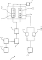
- Fig. 1 illustrates a schematic diagram of a surround audio system 1 according to one exemplary embodiment of the invention.
- the surround audio system 1 includes a superimposition determination unit 24, a signal generator 2, a frequency identifier 11, a heating module 8, a set of transducers 4 placed as part of a right audio channel 5, and left audio channel 6.
- the superimposition determination unit 24 is adapted to process an audio signal which is to be played as the sound 7, and determines a degree of superimposition 25 required for the left audio channel 6 and the right audio channel 5. Once the degree of superimposition 25 is determined, the superimposition determination unit 24 controls the signal generator 2 to generate an excitation signal 3 for the left transducers 15 and right transducers 16 appropriate to generate the determined degree of superimposition of a sound 7. In one embodiment, the superimposition determination unit 24 is not required, rather the signal generator 2 can also be manually handled and the user can use his judgement to identify which transducers 4, 15, 16 are to be used, and accordingly can control the signal generator 2 to generate the excitation signal 3 for those specific transducers 4, 15, 16.
- the signal generator 2 generates the excitation signal 3 and transmit to the set of transducers 4, 15, 16 appropriately, so that those transducers 4, 15, 16 are excited in left audio channel 6 and right audio channel 7 which are required to generate the sound 7 with the audio depth effect.
- the frequency identifier 11 processes the audio signal which is to be played as the sound 7, and identifies a frequency of the sound 7 to be generated, and based on frequency identification, it sends an actuating signal 12 to the heating module 8 for switching on. Once heating module 8 is switched on, it heats up the housing. Heating up the housing helps in making the material of housing flexible which further supports in generating of the sound 7 with precise and required frequency. In one embodiment, the heating module 8 heats specific area of the housing which is in proximity of the transducer 4, 15, 16 required to be excited for generating the sound 7. In one embodiment, the heating module 8 includes various heating elements 10, such that, each element 10 is placed in proximity to each of the transducers 4, 15, 16, so that targeted area of heating can be easily implemented. In one embodiment, the frequency identifier 11 is not required, rather the actuating of the heating module 8 can be manually performed by the user applying his judgement.
- the frequency identifier 11 generates a control signal 13 for switching off the heating module 8
- the frequency identifier 11 sends the actuating signal 12 to the heating module 8 only when the frequency identified to be less than a threshold.
- the rigid material is ineffective in producing the sound. Heating of these material makes them flexible enough to effectuate the generating of sound of low frequencies.
- the threshold at which the actuating signal 12 has to be generated substantially depends on the material of the housing of the surround audio system 1.
- the threshold can be changed according to specific surround audio system 1 based on the material of the housing used. There may be a mechanism provided to easily set that threshold by the user of the surround audio system 1 himself.
- the frequency identifier 11 When the frequency identifier 11 identifies the frequency of the sound 7 subsequently to be generated is a high frequency, the frequency identifier 11 sends a control signal 13 to the heating module 8 to switch off the heating module 8. In an alternate embodiment, the switching off of the heating module 8 need not be automatic through the use of frequency identifier 11, rather the switching off of the heating module 8 can be manually performed.
- a mechanism can also be provided to user to vary the intensity of the heat required for heating the housing of the surround audio system 1. This shall really provide a control at the user hand for a situation where the physical property of the material has substantially changed during usage for long time, and the automatic heating of the heating module 8 is not substantially effective to help in providing a perseverance to qualitative playing of the sound.
- the heating module 8 is not provided, specifically in those case where the material of the housing on which the transducers 4 are to be placed is flexible enough to handle production of sound precisely for a wide frequency range.
- Fig. 2 illustrates a back side 14 of the housing of the surround audio system having placement of transducers 4, 15, 16.
- the back side 14 is shown to be having five pairs of the left transducers 6, and the right transducers 5.
- One pair of the transducers 4, 15, 16 is placed around the center 17 of the back side 14 of the housing of the surround audio system. This pair of transducers 4, 15, 16 helps in getting more superimposed sound of left and right audio channel, which is almost mono sound.
- the left transducers 15 are placed on the left corner 19 of the back side 17 of the audio surround system, and the right transducers 16 are placed onto the right corners 21 of the back side 17 of the housing of the surround audio system.
- These pair of the transducers 4, 15, 16 helps to provide the sound which is having minimal superimposition of left and right audio channel, and provide for a more stereo flavor of the sound.
- the transducers 4, 15, 16 placed at the corners 19, 21, are not required, rather the transducers 4, 15, 16 can be placed more near to the middle 22, 23 of the lines 18, 20, which are running from the corners 19, 21 to the center 17, where such level of stereo sound production is no desired.
- the final two pairs of the left transducers 15, and the right transducers 16 are placed near to a middle 22, 23 of lines 18, 20 running from corners 19, 21 to the center 17 of the back side of the housing of the surround audio system.
- the left transducers 15 are placed near to the middle 22 of lines 18 running from left corners 19 to the center 17 of the back side 14 of the housing and the right transducers 16 are placed near to a middle 23 of the lines 20 running from right corners 21 to the center 17 of the back side 14 of the housing.
- transducers 4, 15, 16 provides for a different degree of the superimposition of the left and right audio channel and somewhere in between to the degree of superimposition provided by the pairs of transducers 4, 15, 16 placed near to the corners 19, 21, and the pair of transducers 4, 15, 16 placed near to the center 17 of the back side 14 of the housing of the surround audio system.
- these transducers 4, 15, 16 need not be placed at middle 22, 23 of the lines 18, 20 running from the corners 19, 21, to the center 17, rather the transducers 4, 15, 16 can be placed at any other place onto the back side 14 of the housing of the surround audio system.
- Each of the transducers 4, 15, 16 is further paired with heating elements 10, so that whenever an area in proximity to the transducers 4, 15, 16 are required to be heated for handling a particular frequency range sound generation, that specific heating element 10 can be activated.
- transducers 4, 15, 16 can be followed in spite of the one which is provided in the Fig 2 , however, it is preferred that the left transducers 15, and the right transducers 16 are symmetrically placed, so as to provide a qualitative sound generation.
- Fig. 3 illustrates a flowchart of a method for producing audio depth effect from a surround audio system according to an embodiment of the invention.
- the audio surround system includes a set of transducers placed on a housing of the surround audio system, each of the transducer are placed to form two audio channels, a right audio channel, and a left audio channel.
- a frequency identifier identifies a frequency of the sound is to be generated and determine, if the frequency is low than in step 303, sending an actuating signal to the heating module for heating the housing of the surround audio system, more specifically the area of the housing is to be heated which is around the transducer required to be excited. If in case the frequency is determined to be higher, the step 307 is performed.
- step 304 the heating module receives the actuating signal and heats the housing of the surround audio system. After heating the surround audio system, step 307 is performed.
- the frequency identifier further determines if a subsequent sound to be produced has a high frequency, it sends a control signal to the heating module, and in step 306, the heating module receives the control signal and switches off the heating module.
- step 307 a degree of superimposition required for left audio channel and right audio channel is determined by a superimposition determination unit to produce a sound with the audio depth effect.
- the superimposition determination unit controls a signal generator unit for generation of an excitation signal for the transducers appropriate to generate the determined degree of superimposition of the sound.
- the signal generator generates and transmits the excitation signal to the particular transducer/s.
- the transducer/s receives the excitation signal and generates of the sound the determined degree of superimposition to produce the audio depth effect. It is to be noted that steps 302 to 306 are optional, and in an embodiment, where the heating module is not required, are not included.
- the present invention provides for a surround audio system 1 for producing an audio depth effect
- the surround audio system 1 includes a signal generator 2 which generates an excitation signal 3 for one or more transducers 4, and further transmits the excitation signal 3, and the set of transducers 4 is placed on a housing of the audio system 1.
- Each of the transducer 4 is placed as a part of two audio channels 5, 6, a right audio channel 5, and a left audio channel 6, wherein the one or more transducers 4 for which the excitation signal 3 is generated is adapted to receive the excitation signal 3 and to generate sound 7 with audio depth effect.
Landscapes
- Physics & Mathematics (AREA)
- Engineering & Computer Science (AREA)
- Acoustics & Sound (AREA)
- Signal Processing (AREA)
- Stereophonic System (AREA)
Claims (8)
- Ein Surround-Audiosystem (1) zur Erzeugung eines Audio-Tiefeneffekts, wobei das Surround-Audiosystem (1) Folgendes umfasst:- einen Signalgenerator (2), der geeignet ist, ein Anregungssignal (3) für einen Satz von Wandlern (4) zu erzeugen, und der geeignet ist, das Anregungssignal (3) weiter zu übertragen; und- der Satz von Wandlern (4), der an einem Gehäuse des Audiosystems (1) angeordnet ist, wobei der Satz von Wandlern so angeordnet ist, dass er zwei Audiokanäle (5, 6) bildet, einen rechten Audiokanal (5) und einen linken Audiokanal (6), wobei die Wandler (4), für die das Anregungssignal (3) erzeugt wird, so angepasst sind, dass sie das Anregungssignal (3) empfangen und Schall (7) mit dem Audiotiefeneffekt erzeugen,- eine Überlagerungsbestimmungseinheit (24), die dazu geeignet ist, einen Überlagerungsgrad (25) zu bestimmen, der für den linken Audiokanal (6) und den rechten Audiokanal (5) erforderlich ist, und wobei die Überlagerungsbestimmungseinheit (24) dazu geeignet ist, den Signalgenerator (2) zu steuern, um das Anregungssignal (3) für den Satz von Wandlern zu erzeugen, der zur Erzeugung des bestimmten Überlagerungsgrades des Tons geeignet ist, wobeidas Surround-Audiosystem ferner angepasst wird:- die Steuerung der Signalgeneratoreinheit (2) durch die Überlagerungsbestimmungseinheit (24) zur Erzeugung des Anregungssignals (3) für den Satz von Wandlern (4), der geeignet ist, den bestimmten Überlagerungsgrad des Tons (7) zu erzeugen,- Erzeugen und Übertragen des Anregungssignals (3) an den Satz von Wandlern durch den Signalgenerator (2), und- Empfang des Anregungssignals (3) durch einen Satz von Wandlern und Erzeugung des Tons (7) mit dem festgelegten Überlagerungsgrad, um den Audio-Tiefeneffekt zu erzeugen,dadurch gekennzeichnet, dass das Surround-Audiosystem ferner Folgendes umfasst:- ein Heizmodul (8) zum Beheizen des Gehäuses des Surround-Audiosystems (1) auf der Grundlage einer Frequenz des zu erzeugenden Tons,
wobei das Heizmodul (8) dazu geeignet ist, einen Bereich (9) des Gehäuses des Surround-Audiosystems (1) zu erwärmen, der sich in der Nähe des Satzes von Wandlern befindet, die durch das Anregungssignal (3) angeregt werden sollen,
wobei das Heizmodul (8) einen Satz von Heizelementen (10) umfasst, so dass jedes der Heizelemente (10) in der Nähe jedes der Wandler aus dem Satz von Wandlern (4) angeordnet ist,
wobei das Surround-Audiosystem (1) ferner eine Frequenzkennung (11) aufweist, die geeignet ist, eine Frequenz des zu erzeugenden Tons (7) zu identifizieren, und die basierend auf der Frequenz des Tons ein Betätigungssignal (12) an das Heizmodul (8) zum Beheizen des Gehäuses des Surround-Audiosystems (1) sendet,
und wobei der Satz von Wandlern (4) auf einer Rückseite (14) des Gehäuses des Surround-Audiosystems (1) angeordnet ist. - Surround-Audiosystem (1) nach Anspruch 1, wobei, wenn die Frequenz des zu erzeugenden Schalls (7) als eine niedrige Frequenz identifiziert wird, die Frequenzkennung (11) so angepasst ist, dass sie das Betätigungssignal (12) an das Heizmodul (8) sendet.
- Surround-Audiosystem (1) nach Anspruch 1 oder 2, wobei, wenn die Frequenzkennung (11) identifiziert, dass die Frequenz des anschließend zu erzeugenden Schalls (7) eine hohe Frequenz ist, die Frequenzkennung (11) so angepasst ist, dass sie ein Steuersignal (13) an das Heizmodul (8) sendet, um das Heizmodul (8) auszuschalten.
- Surround-Audiosystem (1) nach Anspruch 1, wobei der Satz von Wandlern (4) ein Paar aus einem linken Wandler (15) und einem rechten Wandler (16) umfasst, die in unmittelbarer Nähe zueinander an oder in der Nähe eines Zentrums (17) der Rückseite (14) des Gehäuses des Surround-Audiosystems (1) angeordnet sind.
- Surround-Audiosystem (1) nach einem der Ansprüche 1 oder 4, wobei der Satz von Wandlern (4) mehr als ein Paar von linken Wandlern (15) und rechten Wandlern (16) umfasst, die linken Wandler (15) auf oder in der Nähe von Linien (18) angeordnet sind, die von linken Ecken (19) zur Mitte (17) der Rückseite (14) des Gehäuses verlaufen, und die rechten Wandler (16) auf oder in der Nähe von Linien (20) angeordnet sind, die von rechten Ecken (21) zur Mitte (17) der Rückseite (14) des Gehäuses verlaufen, wobei die Wandler (4, 15, 16) symmetrisch angeordnet sind.
- Surround-Audiosystem (1) nach Anspruch 5, wobei der Satz von Wandlern (4) vier Paare von linken Wandlern (15) und rechten Wandlern (16) umfasst, wobei zwei Paare von linken Wandlern (15) und rechten Wandlern (16) auf oder in der Nähe der Ecken (19, 21) der Rückseite (14) des Gehäuses des Surround-Audiosystems (1) angeordnet sind, und die verbleibenden zwei Paare von linken Wandlern (15) und rechten Wandlern (16) so angeordnet sind, dass die linken Wandler (15) auf oder in der Nähe einer Mitte (22) von Linien (18) angeordnet sind, die von den linken Ecken (19) zur Mitte (17) der Rückseite (14) des Gehäuses verlaufen, und die rechten Wandler (16) auf oder in der Nähe einer Mitte (23) der Linien (20) angeordnet sind, die von den rechten Ecken (21) zur Mitte (17) der Rückseite (14) des Gehäuses verlaufen.
- Fernsehgerät mit dem Surround-Audiosystem (1) nach einem der Ansprüche 1 bis 6, wobei die Wandler (4) auf dem Gehäuse des Fernsehgerätes angeordnet sind.
- Verfahren zum Erzeugen eines Audio-Tiefeneffekts durch ein Audio-Surround-System (1), wobei das Audio-Surround-System (1) einen Satz von Wandlern (4) umfasst, die auf einem Gehäuse des Surround-Audiosystems (1) angeordnet sind, wobei der Satz von Wandlern des Wandlers so angeordnet ist, dass er zwei Audiokanäle (5, 6) bildet, einen rechten Audiokanal (5) und einen linken Audiokanal (6), wobei das Verfahren umfasst:- Bestimmen eines Überlagerungsgrades (25), der für den linken Audiokanal (6) und den rechten Audiokanal (5) erforderlich ist, durch eine Überlagerungsbestimmungseinheit (24), um einen Ton (7) mit dem Audiotiefeneffekt zu erzeugen;- Steuern einer Signalgeneratoreinheit (2) durch die Überlagerungsbestimmungseinheit (24) zur Erzeugung eines Anregungssignals (3) für den Satz von Wandlern (4), der geeignet ist, den bestimmten Überlagerungsgrad des Tons (7) zu erzeugen;- Erzeugen und Übertragen des Anregungssignals (3) an den Satz von Wandlern (4) durch den Signalgenerator (2); und- Empfangen des Anregungssignals (3) durch den Satz von Wandlern (4) und Erzeugen des Tons (7) mit dem bestimmten Überlagerungsgrad, um den Audio-Tiefeneffekt zu erzeugen gekennzeichnet durch- Identifizierung der Frequenz des zu erzeugenden Tons (7) durch eine Frequenzkennung (11);- basierend auf der Frequenz des Schalls (7), Erzeugen eines Betätigungssignals (12) durch den Frequenzidentifizierer (11) und Senden des Betätigungssignals (12) an ein Heizmodul (8); und- Empfang des Betätigungssignals (12) durch das Heizmodul (8) und Beheizung des Gehäuses des Surround-Audiosystems (1),
wobei der Satz von Wandlern (4) auf einer Rückseite (14) des Gehäuses des Surround-Audiosystems (1) angeordnet ist,
das Heizmodul einen Satz von Heizelementen (10) umfasst, so dass jedes der Heizelemente (10) in der Nähe jedes der Wandler aus dem Satz von Wandlern (4) angeordnet ist,
und das Heizmodul ist angepasst, um einen Bereich (9) des Gehäuses zu erwärmen, der sich in der Nähe des Satzes von Wandlern befindet, die durch das Anregungssignal (3) angeregt werden sollen.
Priority Applications (2)
| Application Number | Priority Date | Filing Date | Title |
|---|---|---|---|
| EP17183547.3A EP3435683B1 (de) | 2017-07-27 | 2017-07-27 | Audiosystem, fernsehapparat mit dem audiosystem und verfahren zur erzeugung eines audiotiefeneffekts |
| TR2017/11213A TR201711213A2 (tr) | 2017-07-27 | 2017-07-31 | Çevresel Ses Sistemi, Çevresel Ses Sistemini İçeren Bir Televizyon Ve Bir Ses Derinliği Efektinin Üretilmesine Yönelik Yöntem |
Applications Claiming Priority (1)
| Application Number | Priority Date | Filing Date | Title |
|---|---|---|---|
| EP17183547.3A EP3435683B1 (de) | 2017-07-27 | 2017-07-27 | Audiosystem, fernsehapparat mit dem audiosystem und verfahren zur erzeugung eines audiotiefeneffekts |
Publications (2)
| Publication Number | Publication Date |
|---|---|
| EP3435683A1 EP3435683A1 (de) | 2019-01-30 |
| EP3435683B1 true EP3435683B1 (de) | 2020-04-08 |
Family
ID=59631561
Family Applications (1)
| Application Number | Title | Priority Date | Filing Date |
|---|---|---|---|
| EP17183547.3A Active EP3435683B1 (de) | 2017-07-27 | 2017-07-27 | Audiosystem, fernsehapparat mit dem audiosystem und verfahren zur erzeugung eines audiotiefeneffekts |
Country Status (2)
| Country | Link |
|---|---|
| EP (1) | EP3435683B1 (de) |
| TR (1) | TR201711213A2 (de) |
Family Cites Families (6)
| Publication number | Priority date | Publication date | Assignee | Title |
|---|---|---|---|---|
| US4410761A (en) * | 1980-11-05 | 1983-10-18 | Willi Schickedanz | Stereo loudspeaker system for a picture reproducing screen |
| JP5067595B2 (ja) * | 2005-10-17 | 2012-11-07 | ソニー株式会社 | 画像表示装置および方法、並びにプログラム |
| US8199960B2 (en) | 2007-10-11 | 2012-06-12 | Sony Mobile Communications Ab | Integrated speaker and display |
| JP2011250113A (ja) * | 2010-05-26 | 2011-12-08 | Sharp Corp | 表示システム、表示制御方法及びコンピュータプログラム |
| JP2014195166A (ja) | 2013-03-28 | 2014-10-09 | Sharp Corp | 表示装置およびテレビジョン受像機 |
| CN203399244U (zh) | 2013-08-02 | 2014-01-15 | 昆山康佳电子有限公司 | 超薄窄边框电视用机壳音箱一体化结构 |
-
2017
- 2017-07-27 EP EP17183547.3A patent/EP3435683B1/de active Active
- 2017-07-31 TR TR2017/11213A patent/TR201711213A2/tr unknown
Non-Patent Citations (1)
| Title |
|---|
| None * |
Also Published As
| Publication number | Publication date |
|---|---|
| EP3435683A1 (de) | 2019-01-30 |
| TR201711213A2 (tr) | 2019-02-21 |
Similar Documents
| Publication | Publication Date | Title |
|---|---|---|
| US10129647B2 (en) | Wireless sound equipment | |
| EP2839675B1 (de) | Automatische erkennung einer kopfhörerausrichtung | |
| CN107873136B (zh) | 电子设备、外围设备及其控制方法 | |
| US10824277B2 (en) | Electrical device with piezoelectric elements communicating haptically and audibly with user | |
| EP2664165B1 (de) | Vorrichtungen, systeme und verfahren für steuerbare schallbereiche in einem medienraum | |
| CN108833638A (zh) | 发声方法、装置、电子装置及存储介质 | |
| US20110248935A1 (en) | Apparatus and method for sound reproduction | |
| US10321233B2 (en) | Method and portable electronic apparatus for adaptively adjusting playback effect of speakers | |
| KR20010074565A (ko) | 현장감을 느낄 수 있는 가상현실 체험 시스템 | |
| JP2003111194A (ja) | スピーカおよび携帯端末装置 | |
| CN112492095B (zh) | 控制终端的系统、终端、方法、装置和存储介质 | |
| CN110874203A (zh) | 屏幕发声控制器、方法、装置、终端及存储介质 | |
| CN108566602A (zh) | 屏幕组件、背板组件、中框组件、终端设备、发声控制方法和音频设备 | |
| CN111770416B (zh) | 扬声器控制方法、装置及电子设备 | |
| JP2005110216A (ja) | 音響再生装置および携帯端末装置 | |
| JP2018534810A (ja) | 音再生ディスプレイ | |
| WO2013191278A1 (ja) | 電子機器及び制御プログラム並びに情報通知方法 | |
| EP3975582A1 (de) | Klangkastenanordnung, anzeigevorrichtung, audioausgabeverfahren und vorrichtung | |
| CN110572759A (zh) | 电子设备 | |
| CN116033303A (zh) | 耳机、耳机控制方法、装置、电子设备及存储介质 | |
| TWM519370U (zh) | 具有可依據聽力生理狀況調整等化器設定之電子裝置及聲音播放裝置 | |
| US20190253799A1 (en) | Electronic device | |
| EP3435683A1 (de) | Audiosystem, fernsehapparat mit dem audiosystem und verfahren zur erzeugung eines audiotiefeneffekts | |
| CN214901279U (zh) | 一种音箱及系统 | |
| CN115550816A (zh) | 一种用于屏幕的微缝式数字扬声器 |
Legal Events
| Date | Code | Title | Description |
|---|---|---|---|
| PUAI | Public reference made under article 153(3) epc to a published international application that has entered the european phase |
Free format text: ORIGINAL CODE: 0009012 |
|
| STAA | Information on the status of an ep patent application or granted ep patent |
Free format text: STATUS: THE APPLICATION HAS BEEN PUBLISHED |
|
| AK | Designated contracting states |
Kind code of ref document: A1 Designated state(s): AL AT BE BG CH CY CZ DE DK EE ES FI FR GB GR HR HU IE IS IT LI LT LU LV MC MK MT NL NO PL PT RO RS SE SI SK SM TR |
|
| AX | Request for extension of the european patent |
Extension state: BA ME |
|
| STAA | Information on the status of an ep patent application or granted ep patent |
Free format text: STATUS: REQUEST FOR EXAMINATION WAS MADE |
|
| 17P | Request for examination filed |
Effective date: 20190730 |
|
| RBV | Designated contracting states (corrected) |
Designated state(s): AL AT BE BG CH CY CZ DE DK EE ES FI FR GB GR HR HU IE IS IT LI LT LU LV MC MK MT NL NO PL PT RO RS SE SI SK SM TR |
|
| GRAP | Despatch of communication of intention to grant a patent |
Free format text: ORIGINAL CODE: EPIDOSNIGR1 |
|
| STAA | Information on the status of an ep patent application or granted ep patent |
Free format text: STATUS: GRANT OF PATENT IS INTENDED |
|
| RIC1 | Information provided on ipc code assigned before grant |
Ipc: H04R 5/02 20060101AFI20191105BHEP Ipc: H04N 5/64 20060101ALN20191105BHEP Ipc: H04R 1/02 20060101ALN20191105BHEP |
|
| INTG | Intention to grant announced |
Effective date: 20191125 |
|
| GRAS | Grant fee paid |
Free format text: ORIGINAL CODE: EPIDOSNIGR3 |
|
| GRAA | (expected) grant |
Free format text: ORIGINAL CODE: 0009210 |
|
| STAA | Information on the status of an ep patent application or granted ep patent |
Free format text: STATUS: THE PATENT HAS BEEN GRANTED |
|
| AK | Designated contracting states |
Kind code of ref document: B1 Designated state(s): AL AT BE BG CH CY CZ DE DK EE ES FI FR GB GR HR HU IE IS IT LI LT LU LV MC MK MT NL NO PL PT RO RS SE SI SK SM TR |
|
| REG | Reference to a national code |
Ref country code: CH Ref legal event code: EP Ref country code: AT Ref legal event code: REF Ref document number: 1255994 Country of ref document: AT Kind code of ref document: T Effective date: 20200415 |
|
| REG | Reference to a national code |
Ref country code: DE Ref legal event code: R096 Ref document number: 602017014254 Country of ref document: DE |
|
| REG | Reference to a national code |
Ref country code: IE Ref legal event code: FG4D |
|
| REG | Reference to a national code |
Ref country code: NL Ref legal event code: MP Effective date: 20200408 |
|
| REG | Reference to a national code |
Ref country code: LT Ref legal event code: MG4D |
|
| PG25 | Lapsed in a contracting state [announced via postgrant information from national office to epo] |
Ref country code: IS Free format text: LAPSE BECAUSE OF FAILURE TO SUBMIT A TRANSLATION OF THE DESCRIPTION OR TO PAY THE FEE WITHIN THE PRESCRIBED TIME-LIMIT Effective date: 20200808 Ref country code: GR Free format text: LAPSE BECAUSE OF FAILURE TO SUBMIT A TRANSLATION OF THE DESCRIPTION OR TO PAY THE FEE WITHIN THE PRESCRIBED TIME-LIMIT Effective date: 20200709 Ref country code: NO Free format text: LAPSE BECAUSE OF FAILURE TO SUBMIT A TRANSLATION OF THE DESCRIPTION OR TO PAY THE FEE WITHIN THE PRESCRIBED TIME-LIMIT Effective date: 20200708 Ref country code: PT Free format text: LAPSE BECAUSE OF FAILURE TO SUBMIT A TRANSLATION OF THE DESCRIPTION OR TO PAY THE FEE WITHIN THE PRESCRIBED TIME-LIMIT Effective date: 20200817 Ref country code: LT Free format text: LAPSE BECAUSE OF FAILURE TO SUBMIT A TRANSLATION OF THE DESCRIPTION OR TO PAY THE FEE WITHIN THE PRESCRIBED TIME-LIMIT Effective date: 20200408 Ref country code: SE Free format text: LAPSE BECAUSE OF FAILURE TO SUBMIT A TRANSLATION OF THE DESCRIPTION OR TO PAY THE FEE WITHIN THE PRESCRIBED TIME-LIMIT Effective date: 20200408 Ref country code: NL Free format text: LAPSE BECAUSE OF FAILURE TO SUBMIT A TRANSLATION OF THE DESCRIPTION OR TO PAY THE FEE WITHIN THE PRESCRIBED TIME-LIMIT Effective date: 20200408 Ref country code: FI Free format text: LAPSE BECAUSE OF FAILURE TO SUBMIT A TRANSLATION OF THE DESCRIPTION OR TO PAY THE FEE WITHIN THE PRESCRIBED TIME-LIMIT Effective date: 20200408 |
|
| REG | Reference to a national code |
Ref country code: AT Ref legal event code: MK05 Ref document number: 1255994 Country of ref document: AT Kind code of ref document: T Effective date: 20200408 |
|
| PG25 | Lapsed in a contracting state [announced via postgrant information from national office to epo] |
Ref country code: BG Free format text: LAPSE BECAUSE OF FAILURE TO SUBMIT A TRANSLATION OF THE DESCRIPTION OR TO PAY THE FEE WITHIN THE PRESCRIBED TIME-LIMIT Effective date: 20200708 Ref country code: HR Free format text: LAPSE BECAUSE OF FAILURE TO SUBMIT A TRANSLATION OF THE DESCRIPTION OR TO PAY THE FEE WITHIN THE PRESCRIBED TIME-LIMIT Effective date: 20200408 Ref country code: LV Free format text: LAPSE BECAUSE OF FAILURE TO SUBMIT A TRANSLATION OF THE DESCRIPTION OR TO PAY THE FEE WITHIN THE PRESCRIBED TIME-LIMIT Effective date: 20200408 Ref country code: RS Free format text: LAPSE BECAUSE OF FAILURE TO SUBMIT A TRANSLATION OF THE DESCRIPTION OR TO PAY THE FEE WITHIN THE PRESCRIBED TIME-LIMIT Effective date: 20200408 |
|
| PG25 | Lapsed in a contracting state [announced via postgrant information from national office to epo] |
Ref country code: AL Free format text: LAPSE BECAUSE OF FAILURE TO SUBMIT A TRANSLATION OF THE DESCRIPTION OR TO PAY THE FEE WITHIN THE PRESCRIBED TIME-LIMIT Effective date: 20200408 |
|
| REG | Reference to a national code |
Ref country code: DE Ref legal event code: R097 Ref document number: 602017014254 Country of ref document: DE |
|
| PG25 | Lapsed in a contracting state [announced via postgrant information from national office to epo] |
Ref country code: AT Free format text: LAPSE BECAUSE OF FAILURE TO SUBMIT A TRANSLATION OF THE DESCRIPTION OR TO PAY THE FEE WITHIN THE PRESCRIBED TIME-LIMIT Effective date: 20200408 Ref country code: DK Free format text: LAPSE BECAUSE OF FAILURE TO SUBMIT A TRANSLATION OF THE DESCRIPTION OR TO PAY THE FEE WITHIN THE PRESCRIBED TIME-LIMIT Effective date: 20200408 Ref country code: ES Free format text: LAPSE BECAUSE OF FAILURE TO SUBMIT A TRANSLATION OF THE DESCRIPTION OR TO PAY THE FEE WITHIN THE PRESCRIBED TIME-LIMIT Effective date: 20200408 Ref country code: IT Free format text: LAPSE BECAUSE OF FAILURE TO SUBMIT A TRANSLATION OF THE DESCRIPTION OR TO PAY THE FEE WITHIN THE PRESCRIBED TIME-LIMIT Effective date: 20200408 Ref country code: CZ Free format text: LAPSE BECAUSE OF FAILURE TO SUBMIT A TRANSLATION OF THE DESCRIPTION OR TO PAY THE FEE WITHIN THE PRESCRIBED TIME-LIMIT Effective date: 20200408 Ref country code: RO Free format text: LAPSE BECAUSE OF FAILURE TO SUBMIT A TRANSLATION OF THE DESCRIPTION OR TO PAY THE FEE WITHIN THE PRESCRIBED TIME-LIMIT Effective date: 20200408 Ref country code: SM Free format text: LAPSE BECAUSE OF FAILURE TO SUBMIT A TRANSLATION OF THE DESCRIPTION OR TO PAY THE FEE WITHIN THE PRESCRIBED TIME-LIMIT Effective date: 20200408 Ref country code: EE Free format text: LAPSE BECAUSE OF FAILURE TO SUBMIT A TRANSLATION OF THE DESCRIPTION OR TO PAY THE FEE WITHIN THE PRESCRIBED TIME-LIMIT Effective date: 20200408 |
|
| PLBE | No opposition filed within time limit |
Free format text: ORIGINAL CODE: 0009261 |
|
| STAA | Information on the status of an ep patent application or granted ep patent |
Free format text: STATUS: NO OPPOSITION FILED WITHIN TIME LIMIT |
|
| PG25 | Lapsed in a contracting state [announced via postgrant information from national office to epo] |
Ref country code: SK Free format text: LAPSE BECAUSE OF FAILURE TO SUBMIT A TRANSLATION OF THE DESCRIPTION OR TO PAY THE FEE WITHIN THE PRESCRIBED TIME-LIMIT Effective date: 20200408 Ref country code: PL Free format text: LAPSE BECAUSE OF FAILURE TO SUBMIT A TRANSLATION OF THE DESCRIPTION OR TO PAY THE FEE WITHIN THE PRESCRIBED TIME-LIMIT Effective date: 20200408 Ref country code: MC Free format text: LAPSE BECAUSE OF FAILURE TO SUBMIT A TRANSLATION OF THE DESCRIPTION OR TO PAY THE FEE WITHIN THE PRESCRIBED TIME-LIMIT Effective date: 20200408 |
|
| REG | Reference to a national code |
Ref country code: CH Ref legal event code: PL |
|
| 26N | No opposition filed |
Effective date: 20210112 |
|
| REG | Reference to a national code |
Ref country code: BE Ref legal event code: MM Effective date: 20200731 |
|
| PG25 | Lapsed in a contracting state [announced via postgrant information from national office to epo] |
Ref country code: LU Free format text: LAPSE BECAUSE OF NON-PAYMENT OF DUE FEES Effective date: 20200727 Ref country code: LI Free format text: LAPSE BECAUSE OF NON-PAYMENT OF DUE FEES Effective date: 20200731 Ref country code: CH Free format text: LAPSE BECAUSE OF NON-PAYMENT OF DUE FEES Effective date: 20200731 Ref country code: FR Free format text: LAPSE BECAUSE OF NON-PAYMENT OF DUE FEES Effective date: 20200731 |
|
| PG25 | Lapsed in a contracting state [announced via postgrant information from national office to epo] |
Ref country code: BE Free format text: LAPSE BECAUSE OF NON-PAYMENT OF DUE FEES Effective date: 20200731 Ref country code: SI Free format text: LAPSE BECAUSE OF FAILURE TO SUBMIT A TRANSLATION OF THE DESCRIPTION OR TO PAY THE FEE WITHIN THE PRESCRIBED TIME-LIMIT Effective date: 20200408 |
|
| PG25 | Lapsed in a contracting state [announced via postgrant information from national office to epo] |
Ref country code: IE Free format text: LAPSE BECAUSE OF NON-PAYMENT OF DUE FEES Effective date: 20200727 |
|
| PGFP | Annual fee paid to national office [announced via postgrant information from national office to epo] |
Ref country code: GB Payment date: 20210722 Year of fee payment: 5 Ref country code: DE Payment date: 20210721 Year of fee payment: 5 |
|
| PG25 | Lapsed in a contracting state [announced via postgrant information from national office to epo] |
Ref country code: MT Free format text: LAPSE BECAUSE OF FAILURE TO SUBMIT A TRANSLATION OF THE DESCRIPTION OR TO PAY THE FEE WITHIN THE PRESCRIBED TIME-LIMIT Effective date: 20200408 Ref country code: CY Free format text: LAPSE BECAUSE OF FAILURE TO SUBMIT A TRANSLATION OF THE DESCRIPTION OR TO PAY THE FEE WITHIN THE PRESCRIBED TIME-LIMIT Effective date: 20200408 |
|
| PG25 | Lapsed in a contracting state [announced via postgrant information from national office to epo] |
Ref country code: MK Free format text: LAPSE BECAUSE OF FAILURE TO SUBMIT A TRANSLATION OF THE DESCRIPTION OR TO PAY THE FEE WITHIN THE PRESCRIBED TIME-LIMIT Effective date: 20200408 |
|
| REG | Reference to a national code |
Ref country code: DE Ref legal event code: R119 Ref document number: 602017014254 Country of ref document: DE |
|
| GBPC | Gb: european patent ceased through non-payment of renewal fee |
Effective date: 20220727 |
|
| PG25 | Lapsed in a contracting state [announced via postgrant information from national office to epo] |
Ref country code: GB Free format text: LAPSE BECAUSE OF NON-PAYMENT OF DUE FEES Effective date: 20220727 Ref country code: DE Free format text: LAPSE BECAUSE OF NON-PAYMENT OF DUE FEES Effective date: 20230201 |
|
| PGFP | Annual fee paid to national office [announced via postgrant information from national office to epo] |
Ref country code: TR Payment date: 20250725 Year of fee payment: 9 |