EP3434477B1 - Verfahren zur herstellung einer elastischen folie mit dehnbarer struktur und saugfähiger artikel - Google Patents
Verfahren zur herstellung einer elastischen folie mit dehnbarer struktur und saugfähiger artikel Download PDFInfo
- Publication number
- EP3434477B1 EP3434477B1 EP17769800.8A EP17769800A EP3434477B1 EP 3434477 B1 EP3434477 B1 EP 3434477B1 EP 17769800 A EP17769800 A EP 17769800A EP 3434477 B1 EP3434477 B1 EP 3434477B1
- Authority
- EP
- European Patent Office
- Prior art keywords
- elastic film
- sheet layer
- stretchable
- region
- sheet
- Prior art date
- Legal status (The legal status is an assumption and is not a legal conclusion. Google has not performed a legal analysis and makes no representation as to the accuracy of the status listed.)
- Active
Links
- 238000000034 method Methods 0.000 title claims description 26
- 239000002250 absorbent Substances 0.000 title claims description 25
- 230000002745 absorbent Effects 0.000 title claims description 24
- 238000003466 welding Methods 0.000 claims description 93
- 230000008859 change Effects 0.000 claims description 53
- 239000006096 absorbing agent Substances 0.000 claims description 35
- 238000002844 melting Methods 0.000 claims description 24
- 230000008018 melting Effects 0.000 claims description 24
- 230000002093 peripheral effect Effects 0.000 claims description 19
- 230000000149 penetrating effect Effects 0.000 claims description 7
- 239000010410 layer Substances 0.000 description 177
- 239000000835 fiber Substances 0.000 description 44
- 239000000463 material Substances 0.000 description 25
- 239000004745 nonwoven fabric Substances 0.000 description 22
- 238000012360 testing method Methods 0.000 description 22
- 230000007547 defect Effects 0.000 description 21
- 230000008901 benefit Effects 0.000 description 17
- -1 polyethylene Polymers 0.000 description 17
- 239000007788 liquid Substances 0.000 description 15
- 238000010586 diagram Methods 0.000 description 14
- 230000008602 contraction Effects 0.000 description 13
- 229920001971 elastomer Polymers 0.000 description 11
- 238000004519 manufacturing process Methods 0.000 description 10
- 230000008569 process Effects 0.000 description 9
- 239000005060 rubber Substances 0.000 description 9
- 238000007789 sealing Methods 0.000 description 9
- 239000004698 Polyethylene Substances 0.000 description 8
- 239000004743 Polypropylene Substances 0.000 description 7
- 230000035699 permeability Effects 0.000 description 7
- 229920000573 polyethylene Polymers 0.000 description 7
- 230000037303 wrinkles Effects 0.000 description 7
- 238000011161 development Methods 0.000 description 6
- 238000005259 measurement Methods 0.000 description 6
- 229920001155 polypropylene Polymers 0.000 description 6
- 239000004831 Hot glue Substances 0.000 description 5
- 239000003795 chemical substances by application Substances 0.000 description 5
- 230000007423 decrease Effects 0.000 description 4
- 229920000728 polyester Polymers 0.000 description 4
- 229920000742 Cotton Polymers 0.000 description 3
- 229920002544 Olefin fiber Polymers 0.000 description 3
- 229920000297 Rayon Polymers 0.000 description 3
- 239000000853 adhesive Substances 0.000 description 3
- 230000001070 adhesive effect Effects 0.000 description 3
- 238000013459 approach Methods 0.000 description 3
- 238000007664 blowing Methods 0.000 description 3
- 238000005520 cutting process Methods 0.000 description 3
- 239000004767 olefin fiber Substances 0.000 description 3
- 239000002985 plastic film Substances 0.000 description 3
- 238000004080 punching Methods 0.000 description 3
- 239000002964 rayon Substances 0.000 description 3
- 229920002994 synthetic fiber Polymers 0.000 description 3
- 239000012209 synthetic fiber Substances 0.000 description 3
- 210000002700 urine Anatomy 0.000 description 3
- VTYYLEPIZMXCLO-UHFFFAOYSA-L Calcium carbonate Chemical compound [Ca+2].[O-]C([O-])=O VTYYLEPIZMXCLO-UHFFFAOYSA-L 0.000 description 2
- 239000004952 Polyamide Substances 0.000 description 2
- PPBRXRYQALVLMV-UHFFFAOYSA-N Styrene Chemical compound C=CC1=CC=CC=C1 PPBRXRYQALVLMV-UHFFFAOYSA-N 0.000 description 2
- XLOMVQKBTHCTTD-UHFFFAOYSA-N Zinc monoxide Chemical compound [Zn]=O XLOMVQKBTHCTTD-UHFFFAOYSA-N 0.000 description 2
- TZCXTZWJZNENPQ-UHFFFAOYSA-L barium sulfate Chemical compound [Ba+2].[O-]S([O-])(=O)=O TZCXTZWJZNENPQ-UHFFFAOYSA-L 0.000 description 2
- 238000001035 drying Methods 0.000 description 2
- 239000000806 elastomer Substances 0.000 description 2
- 238000010438 heat treatment Methods 0.000 description 2
- 210000003692 ilium Anatomy 0.000 description 2
- 239000000155 melt Substances 0.000 description 2
- 229920003023 plastic Polymers 0.000 description 2
- 239000004033 plastic Substances 0.000 description 2
- 229920002647 polyamide Polymers 0.000 description 2
- 229920000642 polymer Polymers 0.000 description 2
- 229920001296 polysiloxane Polymers 0.000 description 2
- 239000005871 repellent Substances 0.000 description 2
- 238000011144 upstream manufacturing Methods 0.000 description 2
- 206010012444 Dermatitis diaper Diseases 0.000 description 1
- 208000003105 Diaper Rash Diseases 0.000 description 1
- 241000692870 Inachis io Species 0.000 description 1
- 239000004793 Polystyrene Substances 0.000 description 1
- VYPSYNLAJGMNEJ-UHFFFAOYSA-N Silicium dioxide Chemical compound O=[Si]=O VYPSYNLAJGMNEJ-UHFFFAOYSA-N 0.000 description 1
- 239000002174 Styrene-butadiene Substances 0.000 description 1
- GWEVSGVZZGPLCZ-UHFFFAOYSA-N Titan oxide Chemical compound O=[Ti]=O GWEVSGVZZGPLCZ-UHFFFAOYSA-N 0.000 description 1
- 229910001315 Tool steel Inorganic materials 0.000 description 1
- 229920006311 Urethane elastomer Polymers 0.000 description 1
- 238000010521 absorption reaction Methods 0.000 description 1
- 230000001154 acute effect Effects 0.000 description 1
- 150000001336 alkenes Chemical class 0.000 description 1
- 150000001408 amides Chemical class 0.000 description 1
- 230000004888 barrier function Effects 0.000 description 1
- 230000005540 biological transmission Effects 0.000 description 1
- 230000015572 biosynthetic process Effects 0.000 description 1
- MTAZNLWOLGHBHU-UHFFFAOYSA-N butadiene-styrene rubber Chemical compound C=CC=C.C=CC1=CC=CC=C1 MTAZNLWOLGHBHU-UHFFFAOYSA-N 0.000 description 1
- 229910000019 calcium carbonate Inorganic materials 0.000 description 1
- 238000004364 calculation method Methods 0.000 description 1
- 229920002301 cellulose acetate Polymers 0.000 description 1
- 229960000359 chromic chloride Drugs 0.000 description 1
- 239000011636 chromium(III) chloride Substances 0.000 description 1
- 235000007831 chromium(III) chloride Nutrition 0.000 description 1
- 239000004927 clay Substances 0.000 description 1
- 229910052570 clay Inorganic materials 0.000 description 1
- 239000003086 colorant Substances 0.000 description 1
- 230000006835 compression Effects 0.000 description 1
- 238000007906 compression Methods 0.000 description 1
- 238000012790 confirmation Methods 0.000 description 1
- 239000000470 constituent Substances 0.000 description 1
- 238000013016 damping Methods 0.000 description 1
- 230000003247 decreasing effect Effects 0.000 description 1
- 230000000694 effects Effects 0.000 description 1
- 230000007613 environmental effect Effects 0.000 description 1
- 150000002148 esters Chemical class 0.000 description 1
- 239000000945 filler Substances 0.000 description 1
- 239000012530 fluid Substances 0.000 description 1
- 210000004013 groin Anatomy 0.000 description 1
- 230000006872 improvement Effects 0.000 description 1
- 230000005764 inhibitory process Effects 0.000 description 1
- 239000011256 inorganic filler Substances 0.000 description 1
- 229910003475 inorganic filler Inorganic materials 0.000 description 1
- 230000001788 irregular Effects 0.000 description 1
- 238000004898 kneading Methods 0.000 description 1
- 229910052751 metal Inorganic materials 0.000 description 1
- 239000002184 metal Substances 0.000 description 1
- 239000000203 mixture Substances 0.000 description 1
- 238000012986 modification Methods 0.000 description 1
- 230000004048 modification Effects 0.000 description 1
- JRZJOMJEPLMPRA-UHFFFAOYSA-N olefin Natural products CCCCCCCC=C JRZJOMJEPLMPRA-UHFFFAOYSA-N 0.000 description 1
- 229920006255 plastic film Polymers 0.000 description 1
- 229920013716 polyethylene resin Polymers 0.000 description 1
- 229920005672 polyolefin resin Polymers 0.000 description 1
- 229920002223 polystyrene Polymers 0.000 description 1
- 239000004814 polyurethane Substances 0.000 description 1
- 229920002635 polyurethane Polymers 0.000 description 1
- 230000002265 prevention Effects 0.000 description 1
- 238000012545 processing Methods 0.000 description 1
- 230000002940 repellent Effects 0.000 description 1
- 229920005989 resin Polymers 0.000 description 1
- 239000011347 resin Substances 0.000 description 1
- 239000011115 styrene butadiene Substances 0.000 description 1
- 229920003048 styrene butadiene rubber Polymers 0.000 description 1
- 239000000126 substance Substances 0.000 description 1
- 239000002344 surface layer Substances 0.000 description 1
- 239000000454 talc Substances 0.000 description 1
- 229910052623 talc Inorganic materials 0.000 description 1
- 238000009864 tensile test Methods 0.000 description 1
- 238000010998 test method Methods 0.000 description 1
- 229920005992 thermoplastic resin Polymers 0.000 description 1
- OGIDPMRJRNCKJF-UHFFFAOYSA-N titanium oxide Inorganic materials [Ti]=O OGIDPMRJRNCKJF-UHFFFAOYSA-N 0.000 description 1
- 238000009423 ventilation Methods 0.000 description 1
- XLYOFNOQVPJJNP-UHFFFAOYSA-N water Substances O XLYOFNOQVPJJNP-UHFFFAOYSA-N 0.000 description 1
- 239000011787 zinc oxide Substances 0.000 description 1
Images


Classifications
-
- A—HUMAN NECESSITIES
- A61—MEDICAL OR VETERINARY SCIENCE; HYGIENE
- A61F—FILTERS IMPLANTABLE INTO BLOOD VESSELS; PROSTHESES; DEVICES PROVIDING PATENCY TO, OR PREVENTING COLLAPSING OF, TUBULAR STRUCTURES OF THE BODY, e.g. STENTS; ORTHOPAEDIC, NURSING OR CONTRACEPTIVE DEVICES; FOMENTATION; TREATMENT OR PROTECTION OF EYES OR EARS; BANDAGES, DRESSINGS OR ABSORBENT PADS; FIRST-AID KITS
- A61F13/00—Bandages or dressings; Absorbent pads
- A61F13/15—Absorbent pads, e.g. sanitary towels, swabs or tampons for external or internal application to the body; Supporting or fastening means therefor; Tampon applicators
- A61F13/45—Absorbent pads, e.g. sanitary towels, swabs or tampons for external or internal application to the body; Supporting or fastening means therefor; Tampon applicators characterised by the shape
- A61F13/49—Absorbent articles specially adapted to be worn around the waist, e.g. diapers
- A61F13/496—Absorbent articles specially adapted to be worn around the waist, e.g. diapers in the form of pants or briefs
-
- A—HUMAN NECESSITIES
- A61—MEDICAL OR VETERINARY SCIENCE; HYGIENE
- A61F—FILTERS IMPLANTABLE INTO BLOOD VESSELS; PROSTHESES; DEVICES PROVIDING PATENCY TO, OR PREVENTING COLLAPSING OF, TUBULAR STRUCTURES OF THE BODY, e.g. STENTS; ORTHOPAEDIC, NURSING OR CONTRACEPTIVE DEVICES; FOMENTATION; TREATMENT OR PROTECTION OF EYES OR EARS; BANDAGES, DRESSINGS OR ABSORBENT PADS; FIRST-AID KITS
- A61F13/00—Bandages or dressings; Absorbent pads
- A61F13/15—Absorbent pads, e.g. sanitary towels, swabs or tampons for external or internal application to the body; Supporting or fastening means therefor; Tampon applicators
- A61F13/15577—Apparatus or processes for manufacturing
- A61F13/15617—Making absorbent pads from fibres or pulverulent material with or without treatment of the fibres
-
- A—HUMAN NECESSITIES
- A61—MEDICAL OR VETERINARY SCIENCE; HYGIENE
- A61F—FILTERS IMPLANTABLE INTO BLOOD VESSELS; PROSTHESES; DEVICES PROVIDING PATENCY TO, OR PREVENTING COLLAPSING OF, TUBULAR STRUCTURES OF THE BODY, e.g. STENTS; ORTHOPAEDIC, NURSING OR CONTRACEPTIVE DEVICES; FOMENTATION; TREATMENT OR PROTECTION OF EYES OR EARS; BANDAGES, DRESSINGS OR ABSORBENT PADS; FIRST-AID KITS
- A61F13/00—Bandages or dressings; Absorbent pads
- A61F13/15—Absorbent pads, e.g. sanitary towels, swabs or tampons for external or internal application to the body; Supporting or fastening means therefor; Tampon applicators
- A61F13/15577—Apparatus or processes for manufacturing
- A61F13/15585—Apparatus or processes for manufacturing of babies' napkins, e.g. diapers
- A61F13/15593—Apparatus or processes for manufacturing of babies' napkins, e.g. diapers having elastic ribbons fixed thereto; Devices for applying the ribbons
-
- A—HUMAN NECESSITIES
- A61—MEDICAL OR VETERINARY SCIENCE; HYGIENE
- A61F—FILTERS IMPLANTABLE INTO BLOOD VESSELS; PROSTHESES; DEVICES PROVIDING PATENCY TO, OR PREVENTING COLLAPSING OF, TUBULAR STRUCTURES OF THE BODY, e.g. STENTS; ORTHOPAEDIC, NURSING OR CONTRACEPTIVE DEVICES; FOMENTATION; TREATMENT OR PROTECTION OF EYES OR EARS; BANDAGES, DRESSINGS OR ABSORBENT PADS; FIRST-AID KITS
- A61F13/00—Bandages or dressings; Absorbent pads
- A61F13/15—Absorbent pads, e.g. sanitary towels, swabs or tampons for external or internal application to the body; Supporting or fastening means therefor; Tampon applicators
- A61F13/15577—Apparatus or processes for manufacturing
- A61F13/15699—Forming webs by bringing together several webs, e.g. by laminating or folding several webs, with or without additional treatment of the webs
-
- A—HUMAN NECESSITIES
- A61—MEDICAL OR VETERINARY SCIENCE; HYGIENE
- A61F—FILTERS IMPLANTABLE INTO BLOOD VESSELS; PROSTHESES; DEVICES PROVIDING PATENCY TO, OR PREVENTING COLLAPSING OF, TUBULAR STRUCTURES OF THE BODY, e.g. STENTS; ORTHOPAEDIC, NURSING OR CONTRACEPTIVE DEVICES; FOMENTATION; TREATMENT OR PROTECTION OF EYES OR EARS; BANDAGES, DRESSINGS OR ABSORBENT PADS; FIRST-AID KITS
- A61F13/00—Bandages or dressings; Absorbent pads
- A61F13/15—Absorbent pads, e.g. sanitary towels, swabs or tampons for external or internal application to the body; Supporting or fastening means therefor; Tampon applicators
- A61F13/15577—Apparatus or processes for manufacturing
- A61F13/15707—Mechanical treatment, e.g. notching, twisting, compressing, shaping
- A61F13/15739—Sealing, e.g. involving cutting
-
- A—HUMAN NECESSITIES
- A61—MEDICAL OR VETERINARY SCIENCE; HYGIENE
- A61F—FILTERS IMPLANTABLE INTO BLOOD VESSELS; PROSTHESES; DEVICES PROVIDING PATENCY TO, OR PREVENTING COLLAPSING OF, TUBULAR STRUCTURES OF THE BODY, e.g. STENTS; ORTHOPAEDIC, NURSING OR CONTRACEPTIVE DEVICES; FOMENTATION; TREATMENT OR PROTECTION OF EYES OR EARS; BANDAGES, DRESSINGS OR ABSORBENT PADS; FIRST-AID KITS
- A61F13/00—Bandages or dressings; Absorbent pads
- A61F13/15—Absorbent pads, e.g. sanitary towels, swabs or tampons for external or internal application to the body; Supporting or fastening means therefor; Tampon applicators
- A61F13/45—Absorbent pads, e.g. sanitary towels, swabs or tampons for external or internal application to the body; Supporting or fastening means therefor; Tampon applicators characterised by the shape
- A61F13/49—Absorbent articles specially adapted to be worn around the waist, e.g. diapers
- A61F13/49007—Form-fitting, self-adjusting disposable diapers
- A61F13/49009—Form-fitting, self-adjusting disposable diapers with elastic means
- A61F13/49011—Form-fitting, self-adjusting disposable diapers with elastic means the elastic means is located at the waist region
- A61F13/49012—Form-fitting, self-adjusting disposable diapers with elastic means the elastic means is located at the waist region the elastic means being elastic panels
-
- A—HUMAN NECESSITIES
- A61—MEDICAL OR VETERINARY SCIENCE; HYGIENE
- A61F—FILTERS IMPLANTABLE INTO BLOOD VESSELS; PROSTHESES; DEVICES PROVIDING PATENCY TO, OR PREVENTING COLLAPSING OF, TUBULAR STRUCTURES OF THE BODY, e.g. STENTS; ORTHOPAEDIC, NURSING OR CONTRACEPTIVE DEVICES; FOMENTATION; TREATMENT OR PROTECTION OF EYES OR EARS; BANDAGES, DRESSINGS OR ABSORBENT PADS; FIRST-AID KITS
- A61F13/00—Bandages or dressings; Absorbent pads
- A61F13/15—Absorbent pads, e.g. sanitary towels, swabs or tampons for external or internal application to the body; Supporting or fastening means therefor; Tampon applicators
- A61F13/45—Absorbent pads, e.g. sanitary towels, swabs or tampons for external or internal application to the body; Supporting or fastening means therefor; Tampon applicators characterised by the shape
- A61F13/49—Absorbent articles specially adapted to be worn around the waist, e.g. diapers
- A61F13/49007—Form-fitting, self-adjusting disposable diapers
- A61F13/49009—Form-fitting, self-adjusting disposable diapers with elastic means
- A61F13/4902—Form-fitting, self-adjusting disposable diapers with elastic means characterised by the elastic material
-
- B—PERFORMING OPERATIONS; TRANSPORTING
- B29—WORKING OF PLASTICS; WORKING OF SUBSTANCES IN A PLASTIC STATE IN GENERAL
- B29C—SHAPING OR JOINING OF PLASTICS; SHAPING OF MATERIAL IN A PLASTIC STATE, NOT OTHERWISE PROVIDED FOR; AFTER-TREATMENT OF THE SHAPED PRODUCTS, e.g. REPAIRING
- B29C65/00—Joining or sealing of preformed parts, e.g. welding of plastics materials; Apparatus therefor
- B29C65/02—Joining or sealing of preformed parts, e.g. welding of plastics materials; Apparatus therefor by heating, with or without pressure
- B29C65/08—Joining or sealing of preformed parts, e.g. welding of plastics materials; Apparatus therefor by heating, with or without pressure using ultrasonic vibrations
- B29C65/083—Joining or sealing of preformed parts, e.g. welding of plastics materials; Apparatus therefor by heating, with or without pressure using ultrasonic vibrations using a rotary sonotrode or a rotary anvil
- B29C65/086—Joining or sealing of preformed parts, e.g. welding of plastics materials; Apparatus therefor by heating, with or without pressure using ultrasonic vibrations using a rotary sonotrode or a rotary anvil using a rotary anvil
-
- B—PERFORMING OPERATIONS; TRANSPORTING
- B29—WORKING OF PLASTICS; WORKING OF SUBSTANCES IN A PLASTIC STATE IN GENERAL
- B29C—SHAPING OR JOINING OF PLASTICS; SHAPING OF MATERIAL IN A PLASTIC STATE, NOT OTHERWISE PROVIDED FOR; AFTER-TREATMENT OF THE SHAPED PRODUCTS, e.g. REPAIRING
- B29C66/00—General aspects of processes or apparatus for joining preformed parts
- B29C66/01—General aspects dealing with the joint area or with the area to be joined
- B29C66/05—Particular design of joint configurations
- B29C66/10—Particular design of joint configurations particular design of the joint cross-sections
- B29C66/11—Joint cross-sections comprising a single joint-segment, i.e. one of the parts to be joined comprising a single joint-segment in the joint cross-section
- B29C66/112—Single lapped joints
- B29C66/1122—Single lap to lap joints, i.e. overlap joints
-
- B—PERFORMING OPERATIONS; TRANSPORTING
- B29—WORKING OF PLASTICS; WORKING OF SUBSTANCES IN A PLASTIC STATE IN GENERAL
- B29C—SHAPING OR JOINING OF PLASTICS; SHAPING OF MATERIAL IN A PLASTIC STATE, NOT OTHERWISE PROVIDED FOR; AFTER-TREATMENT OF THE SHAPED PRODUCTS, e.g. REPAIRING
- B29C66/00—General aspects of processes or apparatus for joining preformed parts
- B29C66/01—General aspects dealing with the joint area or with the area to be joined
- B29C66/05—Particular design of joint configurations
- B29C66/20—Particular design of joint configurations particular design of the joint lines, e.g. of the weld lines
- B29C66/21—Particular design of joint configurations particular design of the joint lines, e.g. of the weld lines said joint lines being formed by a single dot or dash or by several dots or dashes, i.e. spot joining or spot welding
-
- B—PERFORMING OPERATIONS; TRANSPORTING
- B29—WORKING OF PLASTICS; WORKING OF SUBSTANCES IN A PLASTIC STATE IN GENERAL
- B29C—SHAPING OR JOINING OF PLASTICS; SHAPING OF MATERIAL IN A PLASTIC STATE, NOT OTHERWISE PROVIDED FOR; AFTER-TREATMENT OF THE SHAPED PRODUCTS, e.g. REPAIRING
- B29C66/00—General aspects of processes or apparatus for joining preformed parts
- B29C66/01—General aspects dealing with the joint area or with the area to be joined
- B29C66/344—Stretching or tensioning the joint area during joining
-
- B—PERFORMING OPERATIONS; TRANSPORTING
- B29—WORKING OF PLASTICS; WORKING OF SUBSTANCES IN A PLASTIC STATE IN GENERAL
- B29C—SHAPING OR JOINING OF PLASTICS; SHAPING OF MATERIAL IN A PLASTIC STATE, NOT OTHERWISE PROVIDED FOR; AFTER-TREATMENT OF THE SHAPED PRODUCTS, e.g. REPAIRING
- B29C66/00—General aspects of processes or apparatus for joining preformed parts
- B29C66/40—General aspects of joining substantially flat articles, e.g. plates, sheets or web-like materials; Making flat seams in tubular or hollow articles; Joining single elements to substantially flat surfaces
- B29C66/41—Joining substantially flat articles ; Making flat seams in tubular or hollow articles
- B29C66/43—Joining a relatively small portion of the surface of said articles
- B29C66/433—Casing-in, i.e. enclosing an element between two sheets by an outlined seam
-
- B—PERFORMING OPERATIONS; TRANSPORTING
- B29—WORKING OF PLASTICS; WORKING OF SUBSTANCES IN A PLASTIC STATE IN GENERAL
- B29C—SHAPING OR JOINING OF PLASTICS; SHAPING OF MATERIAL IN A PLASTIC STATE, NOT OTHERWISE PROVIDED FOR; AFTER-TREATMENT OF THE SHAPED PRODUCTS, e.g. REPAIRING
- B29C66/00—General aspects of processes or apparatus for joining preformed parts
- B29C66/70—General aspects of processes or apparatus for joining preformed parts characterised by the composition, physical properties or the structure of the material of the parts to be joined; Joining with non-plastics material
- B29C66/72—General aspects of processes or apparatus for joining preformed parts characterised by the composition, physical properties or the structure of the material of the parts to be joined; Joining with non-plastics material characterised by the structure of the material of the parts to be joined
- B29C66/729—Textile or other fibrous material made from plastics
- B29C66/7294—Non woven mats, e.g. felt
-
- B—PERFORMING OPERATIONS; TRANSPORTING
- B29—WORKING OF PLASTICS; WORKING OF SUBSTANCES IN A PLASTIC STATE IN GENERAL
- B29C—SHAPING OR JOINING OF PLASTICS; SHAPING OF MATERIAL IN A PLASTIC STATE, NOT OTHERWISE PROVIDED FOR; AFTER-TREATMENT OF THE SHAPED PRODUCTS, e.g. REPAIRING
- B29C66/00—General aspects of processes or apparatus for joining preformed parts
- B29C66/80—General aspects of machine operations or constructions and parts thereof
- B29C66/81—General aspects of the pressing elements, i.e. the elements applying pressure on the parts to be joined in the area to be joined, e.g. the welding jaws or clamps
- B29C66/814—General aspects of the pressing elements, i.e. the elements applying pressure on the parts to be joined in the area to be joined, e.g. the welding jaws or clamps characterised by the design of the pressing elements, e.g. of the welding jaws or clamps
- B29C66/8141—General aspects of the pressing elements, i.e. the elements applying pressure on the parts to be joined in the area to be joined, e.g. the welding jaws or clamps characterised by the design of the pressing elements, e.g. of the welding jaws or clamps characterised by the surface geometry of the part of the pressing elements, e.g. welding jaws or clamps, coming into contact with the parts to be joined
- B29C66/81427—General aspects of the pressing elements, i.e. the elements applying pressure on the parts to be joined in the area to be joined, e.g. the welding jaws or clamps characterised by the design of the pressing elements, e.g. of the welding jaws or clamps characterised by the surface geometry of the part of the pressing elements, e.g. welding jaws or clamps, coming into contact with the parts to be joined comprising a single ridge, e.g. for making a weakening line; comprising a single tooth
- B29C66/81429—General aspects of the pressing elements, i.e. the elements applying pressure on the parts to be joined in the area to be joined, e.g. the welding jaws or clamps characterised by the design of the pressing elements, e.g. of the welding jaws or clamps characterised by the surface geometry of the part of the pressing elements, e.g. welding jaws or clamps, coming into contact with the parts to be joined comprising a single ridge, e.g. for making a weakening line; comprising a single tooth comprising a single tooth
-
- B—PERFORMING OPERATIONS; TRANSPORTING
- B29—WORKING OF PLASTICS; WORKING OF SUBSTANCES IN A PLASTIC STATE IN GENERAL
- B29C—SHAPING OR JOINING OF PLASTICS; SHAPING OF MATERIAL IN A PLASTIC STATE, NOT OTHERWISE PROVIDED FOR; AFTER-TREATMENT OF THE SHAPED PRODUCTS, e.g. REPAIRING
- B29C66/00—General aspects of processes or apparatus for joining preformed parts
- B29C66/80—General aspects of machine operations or constructions and parts thereof
- B29C66/81—General aspects of the pressing elements, i.e. the elements applying pressure on the parts to be joined in the area to be joined, e.g. the welding jaws or clamps
- B29C66/814—General aspects of the pressing elements, i.e. the elements applying pressure on the parts to be joined in the area to be joined, e.g. the welding jaws or clamps characterised by the design of the pressing elements, e.g. of the welding jaws or clamps
- B29C66/8141—General aspects of the pressing elements, i.e. the elements applying pressure on the parts to be joined in the area to be joined, e.g. the welding jaws or clamps characterised by the design of the pressing elements, e.g. of the welding jaws or clamps characterised by the surface geometry of the part of the pressing elements, e.g. welding jaws or clamps, coming into contact with the parts to be joined
- B29C66/81433—General aspects of the pressing elements, i.e. the elements applying pressure on the parts to be joined in the area to be joined, e.g. the welding jaws or clamps characterised by the design of the pressing elements, e.g. of the welding jaws or clamps characterised by the surface geometry of the part of the pressing elements, e.g. welding jaws or clamps, coming into contact with the parts to be joined being toothed, i.e. comprising several teeth or pins, or being patterned
-
- B—PERFORMING OPERATIONS; TRANSPORTING
- B29—WORKING OF PLASTICS; WORKING OF SUBSTANCES IN A PLASTIC STATE IN GENERAL
- B29C—SHAPING OR JOINING OF PLASTICS; SHAPING OF MATERIAL IN A PLASTIC STATE, NOT OTHERWISE PROVIDED FOR; AFTER-TREATMENT OF THE SHAPED PRODUCTS, e.g. REPAIRING
- B29C66/00—General aspects of processes or apparatus for joining preformed parts
- B29C66/80—General aspects of machine operations or constructions and parts thereof
- B29C66/83—General aspects of machine operations or constructions and parts thereof characterised by the movement of the joining or pressing tools
- B29C66/834—General aspects of machine operations or constructions and parts thereof characterised by the movement of the joining or pressing tools moving with the parts to be joined
- B29C66/8351—Jaws mounted on rollers, cylinders, drums, bands, belts or chains; Flying jaws
- B29C66/83511—Jaws mounted on rollers, cylinders, drums, bands, belts or chains; Flying jaws jaws mounted on rollers, cylinders or drums
-
- B—PERFORMING OPERATIONS; TRANSPORTING
- B32—LAYERED PRODUCTS
- B32B—LAYERED PRODUCTS, i.e. PRODUCTS BUILT-UP OF STRATA OF FLAT OR NON-FLAT, e.g. CELLULAR OR HONEYCOMB, FORM
- B32B37/00—Methods or apparatus for laminating, e.g. by curing or by ultrasonic bonding
- B32B37/04—Methods or apparatus for laminating, e.g. by curing or by ultrasonic bonding characterised by the partial melting of at least one layer
-
- B—PERFORMING OPERATIONS; TRANSPORTING
- B32—LAYERED PRODUCTS
- B32B—LAYERED PRODUCTS, i.e. PRODUCTS BUILT-UP OF STRATA OF FLAT OR NON-FLAT, e.g. CELLULAR OR HONEYCOMB, FORM
- B32B37/00—Methods or apparatus for laminating, e.g. by curing or by ultrasonic bonding
- B32B37/14—Methods or apparatus for laminating, e.g. by curing or by ultrasonic bonding characterised by the properties of the layers
-
- A—HUMAN NECESSITIES
- A61—MEDICAL OR VETERINARY SCIENCE; HYGIENE
- A61F—FILTERS IMPLANTABLE INTO BLOOD VESSELS; PROSTHESES; DEVICES PROVIDING PATENCY TO, OR PREVENTING COLLAPSING OF, TUBULAR STRUCTURES OF THE BODY, e.g. STENTS; ORTHOPAEDIC, NURSING OR CONTRACEPTIVE DEVICES; FOMENTATION; TREATMENT OR PROTECTION OF EYES OR EARS; BANDAGES, DRESSINGS OR ABSORBENT PADS; FIRST-AID KITS
- A61F13/00—Bandages or dressings; Absorbent pads
- A61F13/15—Absorbent pads, e.g. sanitary towels, swabs or tampons for external or internal application to the body; Supporting or fastening means therefor; Tampon applicators
- A61F13/15577—Apparatus or processes for manufacturing
- A61F2013/15821—Apparatus or processes for manufacturing characterized by the apparatus for manufacturing
- A61F2013/15861—Apparatus or processes for manufacturing characterized by the apparatus for manufacturing for bonding
- A61F2013/15869—Apparatus or processes for manufacturing characterized by the apparatus for manufacturing for bonding with ultrasonic energy
-
- A—HUMAN NECESSITIES
- A61—MEDICAL OR VETERINARY SCIENCE; HYGIENE
- A61F—FILTERS IMPLANTABLE INTO BLOOD VESSELS; PROSTHESES; DEVICES PROVIDING PATENCY TO, OR PREVENTING COLLAPSING OF, TUBULAR STRUCTURES OF THE BODY, e.g. STENTS; ORTHOPAEDIC, NURSING OR CONTRACEPTIVE DEVICES; FOMENTATION; TREATMENT OR PROTECTION OF EYES OR EARS; BANDAGES, DRESSINGS OR ABSORBENT PADS; FIRST-AID KITS
- A61F13/00—Bandages or dressings; Absorbent pads
- A61F13/15—Absorbent pads, e.g. sanitary towels, swabs or tampons for external or internal application to the body; Supporting or fastening means therefor; Tampon applicators
- A61F13/15577—Apparatus or processes for manufacturing
- A61F2013/15821—Apparatus or processes for manufacturing characterized by the apparatus for manufacturing
- A61F2013/15861—Apparatus or processes for manufacturing characterized by the apparatus for manufacturing for bonding
- A61F2013/1591—Apparatus or processes for manufacturing characterized by the apparatus for manufacturing for bonding via adhesive
-
- A—HUMAN NECESSITIES
- A61—MEDICAL OR VETERINARY SCIENCE; HYGIENE
- A61F—FILTERS IMPLANTABLE INTO BLOOD VESSELS; PROSTHESES; DEVICES PROVIDING PATENCY TO, OR PREVENTING COLLAPSING OF, TUBULAR STRUCTURES OF THE BODY, e.g. STENTS; ORTHOPAEDIC, NURSING OR CONTRACEPTIVE DEVICES; FOMENTATION; TREATMENT OR PROTECTION OF EYES OR EARS; BANDAGES, DRESSINGS OR ABSORBENT PADS; FIRST-AID KITS
- A61F13/00—Bandages or dressings; Absorbent pads
- A61F13/15—Absorbent pads, e.g. sanitary towels, swabs or tampons for external or internal application to the body; Supporting or fastening means therefor; Tampon applicators
- A61F13/15577—Apparatus or processes for manufacturing
- A61F2013/15821—Apparatus or processes for manufacturing characterized by the apparatus for manufacturing
- A61F2013/15934—Apparatus or processes for manufacturing characterized by the apparatus for manufacturing for making non-woven
-
- A—HUMAN NECESSITIES
- A61—MEDICAL OR VETERINARY SCIENCE; HYGIENE
- A61F—FILTERS IMPLANTABLE INTO BLOOD VESSELS; PROSTHESES; DEVICES PROVIDING PATENCY TO, OR PREVENTING COLLAPSING OF, TUBULAR STRUCTURES OF THE BODY, e.g. STENTS; ORTHOPAEDIC, NURSING OR CONTRACEPTIVE DEVICES; FOMENTATION; TREATMENT OR PROTECTION OF EYES OR EARS; BANDAGES, DRESSINGS OR ABSORBENT PADS; FIRST-AID KITS
- A61F13/00—Bandages or dressings; Absorbent pads
- A61F13/15—Absorbent pads, e.g. sanitary towels, swabs or tampons for external or internal application to the body; Supporting or fastening means therefor; Tampon applicators
- A61F13/45—Absorbent pads, e.g. sanitary towels, swabs or tampons for external or internal application to the body; Supporting or fastening means therefor; Tampon applicators characterised by the shape
- A61F13/49—Absorbent articles specially adapted to be worn around the waist, e.g. diapers
- A61F13/49007—Form-fitting, self-adjusting disposable diapers
- A61F13/49009—Form-fitting, self-adjusting disposable diapers with elastic means
- A61F13/4902—Form-fitting, self-adjusting disposable diapers with elastic means characterised by the elastic material
- A61F2013/49022—Form-fitting, self-adjusting disposable diapers with elastic means characterised by the elastic material being elastomeric sheet
-
- B—PERFORMING OPERATIONS; TRANSPORTING
- B29—WORKING OF PLASTICS; WORKING OF SUBSTANCES IN A PLASTIC STATE IN GENERAL
- B29C—SHAPING OR JOINING OF PLASTICS; SHAPING OF MATERIAL IN A PLASTIC STATE, NOT OTHERWISE PROVIDED FOR; AFTER-TREATMENT OF THE SHAPED PRODUCTS, e.g. REPAIRING
- B29C66/00—General aspects of processes or apparatus for joining preformed parts
- B29C66/80—General aspects of machine operations or constructions and parts thereof
- B29C66/83—General aspects of machine operations or constructions and parts thereof characterised by the movement of the joining or pressing tools
- B29C66/834—General aspects of machine operations or constructions and parts thereof characterised by the movement of the joining or pressing tools moving with the parts to be joined
- B29C66/8341—Roller, cylinder or drum types; Band or belt types; Ball types
- B29C66/83411—Roller, cylinder or drum types
- B29C66/83415—Roller, cylinder or drum types the contact angle between said rollers, cylinders or drums and said parts to be joined being a non-zero angle
-
- B—PERFORMING OPERATIONS; TRANSPORTING
- B29—WORKING OF PLASTICS; WORKING OF SUBSTANCES IN A PLASTIC STATE IN GENERAL
- B29L—INDEXING SCHEME ASSOCIATED WITH SUBCLASS B29C, RELATING TO PARTICULAR ARTICLES
- B29L2031/00—Other particular articles
- B29L2031/48—Wearing apparel
- B29L2031/4871—Underwear
- B29L2031/4878—Diapers, napkins
-
- B—PERFORMING OPERATIONS; TRANSPORTING
- B32—LAYERED PRODUCTS
- B32B—LAYERED PRODUCTS, i.e. PRODUCTS BUILT-UP OF STRATA OF FLAT OR NON-FLAT, e.g. CELLULAR OR HONEYCOMB, FORM
- B32B2307/00—Properties of the layers or laminate
- B32B2307/50—Properties of the layers or laminate having particular mechanical properties
- B32B2307/51—Elastic
-
- B—PERFORMING OPERATIONS; TRANSPORTING
- B32—LAYERED PRODUCTS
- B32B—LAYERED PRODUCTS, i.e. PRODUCTS BUILT-UP OF STRATA OF FLAT OR NON-FLAT, e.g. CELLULAR OR HONEYCOMB, FORM
- B32B2307/00—Properties of the layers or laminate
- B32B2307/70—Other properties
- B32B2307/726—Permeability to liquids, absorption
- B32B2307/7265—Non-permeable
-
- B—PERFORMING OPERATIONS; TRANSPORTING
- B32—LAYERED PRODUCTS
- B32B—LAYERED PRODUCTS, i.e. PRODUCTS BUILT-UP OF STRATA OF FLAT OR NON-FLAT, e.g. CELLULAR OR HONEYCOMB, FORM
- B32B2555/00—Personal care
- B32B2555/02—Diapers or napkins
-
- B—PERFORMING OPERATIONS; TRANSPORTING
- B32—LAYERED PRODUCTS
- B32B—LAYERED PRODUCTS, i.e. PRODUCTS BUILT-UP OF STRATA OF FLAT OR NON-FLAT, e.g. CELLULAR OR HONEYCOMB, FORM
- B32B27/00—Layered products comprising a layer of synthetic resin
- B32B27/06—Layered products comprising a layer of synthetic resin as the main or only constituent of a layer, which is next to another layer of the same or of a different material
- B32B27/08—Layered products comprising a layer of synthetic resin as the main or only constituent of a layer, which is next to another layer of the same or of a different material of synthetic resin
-
- B—PERFORMING OPERATIONS; TRANSPORTING
- B32—LAYERED PRODUCTS
- B32B—LAYERED PRODUCTS, i.e. PRODUCTS BUILT-UP OF STRATA OF FLAT OR NON-FLAT, e.g. CELLULAR OR HONEYCOMB, FORM
- B32B27/00—Layered products comprising a layer of synthetic resin
- B32B27/12—Layered products comprising a layer of synthetic resin next to a fibrous or filamentary layer
-
- B—PERFORMING OPERATIONS; TRANSPORTING
- B32—LAYERED PRODUCTS
- B32B—LAYERED PRODUCTS, i.e. PRODUCTS BUILT-UP OF STRATA OF FLAT OR NON-FLAT, e.g. CELLULAR OR HONEYCOMB, FORM
- B32B27/00—Layered products comprising a layer of synthetic resin
- B32B27/32—Layered products comprising a layer of synthetic resin comprising polyolefins
-
- B—PERFORMING OPERATIONS; TRANSPORTING
- B32—LAYERED PRODUCTS
- B32B—LAYERED PRODUCTS, i.e. PRODUCTS BUILT-UP OF STRATA OF FLAT OR NON-FLAT, e.g. CELLULAR OR HONEYCOMB, FORM
- B32B37/00—Methods or apparatus for laminating, e.g. by curing or by ultrasonic bonding
- B32B37/14—Methods or apparatus for laminating, e.g. by curing or by ultrasonic bonding characterised by the properties of the layers
- B32B37/144—Methods or apparatus for laminating, e.g. by curing or by ultrasonic bonding characterised by the properties of the layers using layers with different mechanical or chemical conditions or properties, e.g. layers with different thermal shrinkage, layers under tension during bonding
-
- B—PERFORMING OPERATIONS; TRANSPORTING
- B32—LAYERED PRODUCTS
- B32B—LAYERED PRODUCTS, i.e. PRODUCTS BUILT-UP OF STRATA OF FLAT OR NON-FLAT, e.g. CELLULAR OR HONEYCOMB, FORM
- B32B5/00—Layered products characterised by the non- homogeneity or physical structure, i.e. comprising a fibrous, filamentary, particulate or foam layer; Layered products characterised by having a layer differing constitutionally or physically in different parts
- B32B5/02—Layered products characterised by the non- homogeneity or physical structure, i.e. comprising a fibrous, filamentary, particulate or foam layer; Layered products characterised by having a layer differing constitutionally or physically in different parts characterised by structural features of a fibrous or filamentary layer
- B32B5/022—Non-woven fabric
-
- B—PERFORMING OPERATIONS; TRANSPORTING
- B32—LAYERED PRODUCTS
- B32B—LAYERED PRODUCTS, i.e. PRODUCTS BUILT-UP OF STRATA OF FLAT OR NON-FLAT, e.g. CELLULAR OR HONEYCOMB, FORM
- B32B5/00—Layered products characterised by the non- homogeneity or physical structure, i.e. comprising a fibrous, filamentary, particulate or foam layer; Layered products characterised by having a layer differing constitutionally or physically in different parts
- B32B5/02—Layered products characterised by the non- homogeneity or physical structure, i.e. comprising a fibrous, filamentary, particulate or foam layer; Layered products characterised by having a layer differing constitutionally or physically in different parts characterised by structural features of a fibrous or filamentary layer
- B32B5/08—Layered products characterised by the non- homogeneity or physical structure, i.e. comprising a fibrous, filamentary, particulate or foam layer; Layered products characterised by having a layer differing constitutionally or physically in different parts characterised by structural features of a fibrous or filamentary layer the fibres or filaments of a layer being of different substances, e.g. conjugate fibres, mixture of different fibres
Definitions
- the present invention relates to a method of forming an elastic film stretchable structure in which both front and back surface sides of an elastic film are covered with a first sheet layer and a second sheet layer, and an absorbent article having the elastic film stretchable structure.
- elasticity is typically imparted to leg portions, lower torso portion, etc. to improve fitting to the surfaces of body.
- a typical approach to impart elasticity is attaching of elongated elastically stretchable members, such as rubber threads, in a state stretched in a longitudinal direction thereof.
- rubber threads are disposed and fixed in the width direction at intervals in some embodiments.
- an approach to impart excellent surface fitting is attaching of elastic film in a state stretched in a direction of imparting elasticity (for example, see Patent Literature 1) .
- a stretchable region is formed by stacking an elastic film between a first sheet layer and a second sheet layer, and the first sheet layer and the second sheet layer are bonded via through-holes formed in the elastic film at a large number of dot-like sheet bonded portions arranged at intervals in a stretchable direction and a direction orthogonal thereto respectively while the elastic film is stretched in the stretchable direction along the surfaces thereof.
- This elastic film stretchable structure has advantages as follows: surface fitting is excellent; the first sheet layer and the second sheet layer are not bonded to the elastic film and bonded each other but at an extremely low level, thus the elastic film stretchable structure has a satisfactory flexibility; and the through-holes of the elastic film contribute to improvement in air permeability.
- the elastic film stretchable structure described above may be manufactured by forming the sheet bonded portions by bonding the first sheet layer and the second sheet layer at a large number of positions arranged at intervals in a state in which the elastic film is interposed between the first sheet layer and the second sheet layer while being stretched in the stretchable direction.
- the elastic film stretchable structure having stretching stresses or elongations at the elastic limit depending on the sites is obtained by arranging the sheet bonded portions in a pattern including a plurality of regions having different area rates.
- Heat sealing or a hot-melt adhesive can be used as a bonding scheme of the first sheet layer and the second sheet layer.
- it is desirable to adopt ultrasonic welding because bonding may be performed in a fine pattern, and decrease in flexibility is small in the ultrasonic welding.
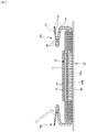
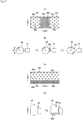
- Fig. 20 illustrates an example of an ultrasonic sealing apparatus.
- a first sheet layer 20A, an elastic film 30, and a second sheet layer 20B are fed between an ultrasonic horn 61 and an anvil roll 60 having protrusions 60a formed in a pattern of the sheet bonded portions 40 on an external surface.
- the elastic film 30 is stretched to a predetermined stretch rate in an MD (machine direction, flow direction) on a path from a nip position by the feed drive roll 63 and the nip roll 62 to a sealing position by the anvil roll 60 and the ultrasonic horn 61.
- Reference symbol 62 denotes the nip roll.
- the first sheet layer 20A, the elastic film 30, and the second sheet layer 20B fed between the anvil roll 60 and the ultrasonic horn 61 are, in a stacked state in this order, heated by ultrasonic vibration energy of the ultrasonic horn 61 while being pressed between the protrusions 60a and the ultrasonic horn 61.
- the through-holes 31 are formed in the elastic film 30 by melting only the elastic film 30 or melting the elastic film 30 and at least one of the first sheet layer 20A and the second sheet layer 20B.
- the first sheet layer 20A and the second sheet layer 20B are bonded via the through-holes 31.
- the area rate of the sheet bonded portions 40 may be changed in at least one of the MD and a CD (cross direction) by providing regions of a plurality of patterns having different sizes, shapes, and arrangements (intervals between adjacent sheet bonded portions in a roll length direction and those in a roll circumferential direction) of the protrusions 60a such that the area rate of the protrusions 60a of the anvil roll 60 changes in at least one of the roll circumferential direction and the roll length direction.
- the area rate is changed from the high-area-rate-region 60H to the low-area-rate-region 60L, if a difference in area rate therebetween is large, for example, about 8%, the high-area-rate-region 60H of the protrusions 60a in the anvil roll 60 will thermally expand to a higher degree as illustrated in Fig.
- Patent Literature 2 discloses an elastic laminate sheet comprising a laminate comprising an elastomer layer and a nonwoven fabric provided on at least one surface of the elastomer layer.
- a main obj ect of the invention is to prevent a welding defect in a method of forming an elastic film stretchable structure by ultrasonic welding.
- a method of forming an elastic film stretchable structure comprising:
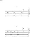
- the difference between the maximum value and the minimum value in a change of the area rate of the protrusions in the roll circumferential direction of the anvil roll is set to 4.5% or less in this way, which makes a difference in thermal expansion in the roll circumferential direction small during a long time operation.
- the lack of time to control the clearance of the ultrasonic horn rarely occurs, and a welding defect is hardly caused.
- a method of obtaining the difference between the maximum value and the minimum value in the change of the area rate of the protrusions (equivalent to the sheet bonded portions) will be described below.
- a method of forming an elastic film stretchable structure comprising:
- the difference between the maximum value and the minimum value in the change of the area rate of the protrusions in the roll length direction of the anvil roll is set to 1.5% or less in this way, which makes a difference in thermal expansion in the roll length direction small during a long time operation.
- a clearance between the ultrasonic horn and the anvil roll rarely becomes excessively large in a region in which thermal expansion is small in the CD, and a welding defect hardly occurs .
- a method of forming an elastic film stretchable structure comprising:
- the difference between the maximum value and the minimum value in the change of the area rate of the protrusions may be set with respect to all protrusions of one anvil roll, it is desirable that the difference between the maximum value and the minimum value in the change of the area rate of the protrusions in the roll length direction is set to 1.5% or less for each site in which welding is performed by each ultrasonic horn as in this fourth aspect.
- a melting point of the first sheet layer and the second sheet layer is 85 to 190°C
- a melting point of the elastic film is 80 to 145°C
- a difference between the melting point of the first sheet layer and the second sheet layer and the melting point of the elastic film is 60 to 80°C.
- An absorbent article comprising an absorber that absorbs excrement, wherein the absorbent article has an elastic film stretchable structure in which an elastic film is stacked between a first sheet layer and a second sheet layer and the first sheet layer and the second sheet layer are bonded via through-holes penetrating the elastic film at a plurality of sheet bonded portions arranged at intervals, a region having the elastic film stretchable structure has a plurality of bonded regions in which area rates of the sheet bonded portions are different from each other, the region having the elastic film stretchable structure includes a site totally in a stretchable direction and at least partly in a direction orthogonal to the stretchable direction, the site has a portion in which an area rate of the sheet bonded portions changes in the stretchable direction, and a difference between a maximum value and a minimum value in a change of the area rate of the sheet bonded portions in the stretchable direction is 4.5% or less.
- Such an elastic film stretchable structure is excellent in structural homogeneity in the stretchable direction in the region having the elastic film stretchable structure, and thus has more uniform texture, flexibility, elasticity, etc.
- such an elastic film stretchable structure may be formed by the first aspect.
- the sheet bonded portions are formed to have substantially the same size and arrangement of those of the protrusions of the anvil roll, and thus the same operational advantage as that in the first aspect is achieved.
- An absorbent article comprising an absorber that absorbs excrement, wherein the absorbent article has an elastic film stretchable structure in which an elastic film is stacked between a first sheet layer and a second sheet layer and the first sheet layer and the second sheet layer are bonded via through-holes penetrating the elastic film at a plurality of sheet bonded portions arranged at intervals, a region having the elastic film stretchable structure has a plurality of bonded regions in which area rates of the sheet bonded portions are different from each other, the region having the elastic film stretchable structure includes a site totally in a stretchable direction and at least partly in a direction orthogonal to the stretchable direction, the site has a portion in which an area rate of the sheet bonded portions changes in the direction orthogonal to the stretchable direction, and a difference between a maximum value and a minimum value in a change of the area rate of the sheet bonded portions in the direction orthogonal to the stretchable direction is 1.5% or less.
- Such an elastic film stretchable structure is excellent in structural homogeneity in the direction orthogonal to the stretchable direction in the region having the elastic film stretchable structure, and thus has more uniform texture, flexibility, elasticity, etc.
- such an elastic film stretchable structure may be formed by the second aspect.
- the sheet bonded portions are formed to have substantially the same size and arrangement of those of the protrusions of the anvil roll, and thus the same operational advantage as that in the second aspect is achieved.
- An absorbent article comprising an absorber that absorbs excrement, wherein the absorbent article has an elastic film stretchable structure in which an elastic film is stacked between a first sheet layer and a second sheet layer and the first sheet layer and the second sheet layer are bonded via through-holes penetrating the elastic film at a plurality of sheet bonded portions arranged at intervals, a region having the elastic film stretchable structure has a plurality of bonded regions in which area rates of the sheet bonded portions are different from each other, the region having the elastic film stretchable structure includes a site totally in a stretchable direction and at least partly in a direction orthogonal to the stretchable direction, and the site has a portion in which an area rate of the sheet bonded portions changes in the stretchable direction and the direction orthogonal to the stretchable direction, a difference between a maximum value and a minimum value in a change of the area rate of the sheet bonded portions in the stretchable direction is 4.5% or less, and a difference between a maximum value and a minimum value in a change
- Such an elastic film stretchable structure is excellent in structural homogeneity in the stretchable direction and the direction orthogonal to the stretchable direction in the region having the elastic film stretchable structure, and thus has more uniform texture, flexibility, elasticity, etc.
- such an elastic film stretchable structure may be formed by the third aspect.
- the sheet bonded portions are formed to have substantially the same size and arrangement of those of the protrusions of the anvil roll, and thus the same operational advantage as that in the third aspect is achieved.
- the absorbent article is an underpants-type disposable diaper including an outer member disposed in a front body and a back body provided individually or as one unit, and an inner member including the absorber and attached to the outer member, both side portions of the outer member in the front body and both side portions of the outer member in the back body being bonded, respectively, and having a waist opening and a pair of left and right leg openings, and the outer member in at least one of the front body and the back body has the elastic film stretchable structure throughout a range including a whole of the width direction thereof such that a stretchable direction thereof is the width direction.
- the underpants-type disposable diaper particularly attaches importance to surface fitting among absorbent articles, and requires a wide stretchable region. Therefore, the fifth to ninth aspects are suitable for the stretchable region of such an underpants-type disposable diaper. For the same reason, the first to fifth aspects are suitable for manufacturing the outer member of the underpants-type disposable diaper.
- a dotted portion in a cross-sectional view indicates bonding means such as a hot-melt adhesive.
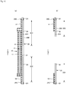
- Fig. 1 to Fig. 6 illustrate an underpants-type disposable diaper.
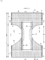
- This underpants-type disposable diaper (hereinafter also simply referred to as a diaper) has an outer member 20 disposed in a front body F and a back body B and an inner member 10 attached to the outer member 20 as one unit. Further, in the inner member 10, is formed by interposing an absorber 13 between a liquid pervious top sheet 11 and a liquid impervious sheet 12.
- the inner member 10 and the outer member 20 are folded at a center in a front-back direction LD (vertical direction) corresponding to a boundary between the front body F and the back body B, both side portions thereof are bonded to each other by heat sealing, a hot-melt adhesive, etc. to form side seal portions 21, and a waist opening and a pair of right and left leg openings are formed.
- bonding means such as a hot-melt adhesive
- the inner member 10 has a structure in which the absorber 13 is interposed between the liquid pervious top sheet 11 and the liquid impervious sheet 12 made of polyethylene, etc., and absorbs and retains excretory fluid passing through the top sheet 11.
- the inner member 10 may have any planar shape and typically has a substantially rectangular shape as shown in Fig. 1 .
- the liquid pervious top sheet 11 that covers a front surface side (skin side) of the absorber 13 is preferably composed of perforated or imperforate nonwoven fabric or a porous plastic sheet.
- the raw fibers of the nonwoven fabric include synthetic fibers, such as olefin fibers, e.g., polyethylene and polypropylene, polyester fibers, and polyamide fibers; recycled fibers, such as rayon and cupra; and natural fibers, such as cotton.
- the nonwoven fabric can be produced by any process, for example, spun lacing, spun bonding, thermal bonding, melt blowing, or needle punching. Among these processes, preferred are spun lacing in view of flexibility and drape characteristics and thermal bonding in view of bulky soft products. A large number of through-holes formed in the liquid pervious top sheet 11 facilitate absorption of urine and achieve dry touch characteristics.
- the liquid pervious top sheet 11 extends around side edge portions of the absorber 13 and extends to the back surface side of the absorber 13.
- a liquid impervious plastic sheet such as polyethylene sheet or polypropylene sheet is used as the liquid impervious sheet 12 that covers the back surface side (non-skin contact side) of the absorber 13.
- permeable sheets have been preferably used in view of preventing stuffiness.
- This water-block permeable sheet is a micro-porous sheet prepared through melt-kneading an olefin resin, for example, polyethylene resin or polypropylene resin, and inorganic filler, forming a sheet with the kneaded materials, and then uniaxially or biaxially stretching the sheet.
- the absorber 13 may be composed of a well-known basic component, such as an accumulatedbody of pulp fibers, an assembly of filaments, composed of, for example, cellulose acetate, or nonwoven fabric, and the absorber 13 may include as necessary high-absorbent polymer mixed or fixed to the basic component.
- the absorber 13 may be wrapped with a liquid-permeable and liquid-retainable wrapping sheet 14, such as a crepe sheet, to retain the shape and polymers, as required.
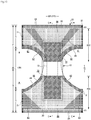
- the absorber 13 has a substantially hourglass shape having at a crotch portion, a narrowing part 13N with a width being narrower than those of the both front and back sides. However, it is possible to adopt an appropriate shape such as a rectangular shape.
- the size of the narrowing part 13N may be appropriately determined.
- the length of the narrowing part 13N in the front-back direction LD may be set to about 20 to 50% of the entire length of the diaper, and the width of a narrowest part thereof may be set to about 40 to 60% of the entire width of the absorber 13.
- the inner body 10 has a substantially rectangular planar shape in the case of the absorber with such a narrowing part 13N, the inner member 10 has non-absorber side portions free of the absorber 13 according to the narrowing part 13N of the absorber 13.
- each of the three-dimensional gathers BS is formed by folding a gather nonwoven fabric 15 into a duplicate sheet, including a fixed portion fixed to a side portion of the back surface of the inner member; a main body portion extending from the fixed portion around the side of the inner member to the side portion of the front surface of the inner member; fallen portions formed by fixing the front end portion and back end portion of the main body portion to the side portion of the front surface of the inner member in a fallen state; and a free part formed in an un-fixed state between the fallen portions.
- elongated gather elastic members 16 are disposed, for example, at a tip portion of the free part, between double sheets. As indicated by a two-dot chain line in Fig. 5 , the free part is erected by elastic stretching force of the gather elastic members 16 to form the three-dimensional gather BS in a product state.
- the liquid impervious sheet 12 is folded back to the back surface side together with the liquid pervious top sheet 11 at both sides of the absorber 13 in the width direction WD. It is desirable that the liquid impervious sheet 12 is opaque to block transmission of brown color of stool and urine.
- Preferred examples of the opacifying agent compounded in the plastic film include colorant or filler, such as calcium carbonate, titanium oxide, zinc oxide, white carbon, clay, talc, and barium sulfate.
- the gather elastic member 16 may be composed of commodity materials, for example, styrene rubber, olefin rubber, urethane rubber, ester rubber, polyurethanes, polyethylene, polystyrene, styrene-butadiene, silicones, and polyester.
- the gather elastic members 16 preferably have a fineness of 925 dtex or less and are disposed under a tension of 150% to 350% at an interval of 7.0 mm or less to be hidden from outside view.
- the gather elastic member 16 may have a string shape shown in the drawing or a tape shape with an appropriate width.
- the gather nonwoven fabric 15 maybe composed of raw fibers including synthetic fibers, such as olefin fibers of, for example, polyethylene fibers or polypropylene fibers; polyester fibers and amide fibers; recycled fibers of, for example, rayon and cupra; and natural fibers such as cotton .
- the gather nonwoven fabric maybe prepared by any appropriate process, for example, spun bonding, thermal bonding, melt blowing, or needle punching.
- the basis weight should be reduced for production of a nonwoven fabric that can prevent stuffiness and has high air permeability.
- the gather nonwoven fabric 15 is a water-repellent nonwoven fabric coated with a water repellent agent, for example, a silicone-based agent, a paraffin-metallic agent, or an alkyl chromic chloride agent to prevent permeability of urine, etc., to prevent diaper rash, and to enhance feeling to skin (dryness).
- a water repellent agent for example, a silicone-based agent, a paraffin-metallic agent, or an alkyl chromic chloride agent to prevent permeability of urine, etc., to prevent diaper rash, and to enhance feeling to skin (dryness).
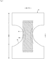
- the back surface of the inner member 10 is fixed to the internal surface of the outer member 20 by a hot-melt adhesive, etc. in an internal and external fixed region 10B (shaded area) .
- the internal and external fixed region 10B extends from a front side to a back side of a range having the narrowing part 13N of the absorber 13 in the front-back direction LD.
- Side edges of the internal and external fixed region 10B are preferably positioned at lateral sides of a middle of a range overlapping the narrowing part 13N of the absorber 13 in the width direction WD.
- the internal and external fixed region 10B is fixed to the outer member 20 throughout substantially the entire part in the width direction WD and the substantially the entire part in the front-back direction LD in the inner member 10.
- front and back cover sheets 51 and 52 may be provided to cover the front and back end portions of the inner member 10 attached to the internal surface of the outer member 20 and to prevent leakage from the front and back edges of the inner member 10.
- the illustrated mode will be described in more detail.
- the front cover sheet 51 extends along a whole part in the width direction WD of the front body F on the internal surface of the outer member 20 from an internal surface of the folded part 20C in a waist region 23 to a position overlapping with a front end portion of the inner member 10.
- the back cover sheet 52 extends along a whole part in the width direction WD of the back body B on the internal surface of the outer member 20 from the internal surface of the folded part 20C in the waist region 23 to a position overlapping with the back end portion of the inner member 10.
- Minor non-bonded regions may be provided along a whole part in the width direction WD (or only at a central portion) at edge portions of the front and back cover sheets 51 and 52 on the crotch side.
- the front and back cover sheets 51 and 52 having such non-bonded regions can prevent leakage of the adhesive and function as barriers against leakage when slightly suspended from the top sheet.
- the folded part 20C formed by folding back the outer member 20 toward the inner surface side of the diaper are respectively extended to portions overlapping with the inner member 10 to have the same function as that of the cover sheets 51 and 52.
- a side edge of the outer member 20 may be positioned closer to a central side than a side edge of the inner member 10 in the width direction WD as in the illustrated mode, or may be positioned closer to an outer side than the side edge of the inner member 10 in the width direction WD.
- the outer member 20 has a lower torso portion T corresponding to a range in the front-back direction LD of each side seal portion 21, and an intermediate portion L corresponding to a range in the front-back direction LD between the lower torso portion T of the front body F and the lower torso portion T of the back body B.
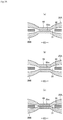
- an elastic film 30 is stacked between a first sheet layer 20A and a second sheet layer 20B as illustrated in Fig. 2 and Fig. 4 to Fig. 6 , and the first sheet layer 20A and the second sheet layer 20B have an elastic film stretchable structure 20X, a stretchable direction ED of which is corresponding to the width direction WD, are bonded via through-holes 31 penetrating the elastic film 30 at a large number of sheet bonded portions 40 arranged at intervals as illustrated in Fig. 7 .
- a planar shape of the outer member 20 is formed including concave-shaped leg lines 29 such that both side edges of the intermediate portion L in the width direction WD form the leg openings, and corresponds to a shape similar to an hourglass as a whole.
- the outer member 20 may be divided into the front body F and the back body B and disposed such that the front body F and the back body B are spaced apart from each other in the front-back direction LD in the crotch portion.
- the modes illustrated in Fig. 1 and Fig. 2 correspond to a mode in which the elastic film stretchable structure 20X extends to the waist region 23.
- the waist portion elastic members 24 correspond to elongated elastic members such as a plurality of rubber threads disposed at intervals in the front-back direction LD, and apply a stretching force to tighten around the waist of the body.
- the waist portion elastic members 24 are not disposed substantially in a bundle with a close spacing, and three or more, preferably five or more members are disposed at intervals of about 3 to 8 mm to form a predetermined stretchable zone.
- a stretch rate of the waist portion elastic members 24 in fixing may be appropriately determined. However, the stretch rate may be set to about 230 to 320% in the case of normal adult use.
- Rubber threads are used as the waist portion elastic members 24 in an illustrated example. However, for example, another elongated elastic member such as flat rubber may be used.
- the elastic film stretchable structure 20X may not be provided in the intermediate portion L between the lower torso portion T of the front body F and the lower torso portion T of the back body B, the stretchable structure 20X may be continuously provided in the front-back direction LD from the inside of the lower torso portion T of the front body F to the inside of the lower torso portion T of the back body B through the intermediate portion L, or the elastic film stretchable structure 20X may be provided only in any one of the front body F and the back body B.
- a shape of each of the sheet bonded portions 40 and a shape of each of the through-holes 31 in a natural length state may be appropriately determined.
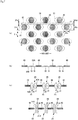
- an arbitrary shape such as a perfect circle (see Fig. 7 and Fig. 8 ), an ellipse, a polygon such as a triangle, a rectangle (see Fig. 9 to Fig. 12 ), a rhombus (see Fig. 13(b) ), etc., a convex lens shape (seeFig. 13(a)), a concave lens shape (see Fig. 14 (a) ), a star shape, a cloud shape, etc.
- the dimensions of each of the sheet bonded portions are not particularly restricted.
- a maximum length 40y is preferably set to 0.5 to 3.0 mm, particularly 0.7 to 1.1 mm, and a maximum width 40x is preferably set to 0.1 to 3.0 mm, particularly 0.1 to 1.1 mm in a case of a shape which is long in an orthogonal direction XD orthogonal to the stretchable direction ED.
- a size of each of the sheet bonded portions 40 may be appropriately determined. However, when the size is excessively large, the hardness of the sheet bonded portions 40 has a significant influence on touch. When the size is excessively small, a bonded area is small, and materials may not be sufficiently attached to each other. Thus, in general, an area of each of the sheet bonded portions 40 is preferably set to about 0.14 to 3.5 mm 2 . An area of an opening of each of the through-holes 31 may be greater than or equal to that of each of the sheet bonded portions since the sheet bonded portions are formed via the through-holes 31, and the area is preferably set to about 1 to 1.5 times the area of each of the sheet bonded portions.
- the area of the opening of each of the through-holes 31 refers to a value in a natural length state and in a state where the elastic film 30,the first sheet layer 20A and the second sheet layer 20B are provided in one unit, not in a state of the elastic film 30 alone, and refers to a minimum value in a case in which the area of the opening of each of the through-holes 31 is not uniform in a thickness direction such as a case in which the area is different between a front and a back of the elastic film 30.
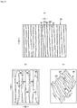
- planar geometries of the sheet bonded portions 40 and the through-holes 31 may be appropriately determined. However, it is preferable to adopt a planar array in which the sheet bonded portions 40 and the through-holes 31 are regularly repeated , such as an oblique lattice shape illustrated in Fig. 21(a) , a hexagonal lattice shape (also referred to as a staggered lattice) illustrated in Fig. 21(b) , a square lattice shape illustrated in Fig. 21(c) , a rectangular lattice shape illustrated in Fig. 21(d) , a parallelotope lattice shape illustrated in Fig.
- a planar array in which the sheet bonded portions 40 and the through-holes 31 are regularly repeated such as an oblique lattice shape illustrated in Fig. 21(a) , a hexagonal lattice shape (also referred to as a staggered lattice) illustrated in Fig. 21(b)
- the first sheet layer 20A and the second sheet layer 20B are bonded in the sheet bonded portions 40 via the through-holes 31 formed in the elastic film 30.
- Ultrasonic welding is desirable as bonding means of the first sheet layer 20A and the second sheet layer 20B in the sheet bonded portions 40 in that the first sheet layer 20A and the second sheet layer 20B do not become hard.
- the sheet bonded portions 40 are formed by material welding
- a particularly preferable mode is a mode in which the first sheet layer 20A and the second sheet layer 20B are bonded by the melted and solidified material 20m corresponding to a part of the first sheet layer 20A and the second sheet layer 20B and the melted and solidified material 30m corresponding to a whole or a most part of the elastic film 30 in the sheet bonded portions 40.
- the melted and solidified material 30m of the elastic film 30 is seen in the melted and solidified material 20m with the fibers of the first sheet layer 20A or the second sheet layer 20B in the third welding mode illustrated in Fig.
- first sheet layer 20A and the second sheet layer 20B are bonded using the melted and solidified material 20m corresponding to a most part or a part of at least one of the first sheet layer 20A and the second sheet layer 20B as an adhesive as in the first welding mode or the third welding mode, it is preferable that a part of the first sheet layer 20A and the second sheet layer 20B is not melted in order not to harden the sheet bonded portions 40.
- a case in which a part of the first sheet layer 20A and the second sheet layer 20B is not melted includes a mode in which for all fibers of the sheet bonded portions 40, a core (including a central portion of each component fiber of a conjugate fiber in addition to a core of the conjugate fiber) remains while a surrounding portion (including a portion on a surface layer side of each component fiber of a conjugate fiber in addition to a sheath in the conjugate fiber) melts; a mode in which some fibers do not melt at all while all remaining fibers melt; or a mode in which a core remains while a surrounding portion melts.
- the elastic film 30 may be interposed between the first sheet layer 20A and the second sheet layer 20B, portions to be the sheet bonded portions 40 may be pressed and heated, and only the elastic film 30 may be melted, thereby performing manufacture.
- the elastic film 30 may be interposed between the first sheet layer 20A and the second sheet layer 20B, the portions to be the sheet bonded portions 40 may be pressed and heated, and at least one of the first sheet layer 20A and the second sheet layer 20B and the elastic film 30 may be melted to perform the welding.
- the melting point of the elastic film 30 is preferably about 80 to 145°C
- melting points of the first sheet layer 20A and the second sheet layer 20B are preferably about 85 to 190°C, particularly, 150 to 190°C
- a difference between the melting points of the first sheet layer 20A and the second sheet layer 20B and the melting point of the elastic film 30 is preferably about 60 to 90°C, particularly about 60 to 80°C.
- the heating temperature is preferably set to 100 to 150°C.
- the melted and solidified material 30m of the elastic film 30 may infiltrate among fibers throughout the whole thickness direction of the first sheet layer 20A and the second sheet layer 20B of the sheet bonded portions 40 as illustrated in Fig. 18(c) .
- flexibility of the sheet bonded portions 40 becomes high in a mode in which the melted and solidified material 30m infiltrates among fibers in the thickness direction halfway as illustrated in Figs. 17(b), 17(c) , and Fig. 18(a) , or a mode in which the melted and solidified material 30m hardly infiltrates among the fibers of the first sheet layer 20A and the second sheet layer 20B as illustrated in Fig. 18(b) .
- Fig. 20 illustrates an example of an ultrasonic sealing device suitable for forming the second welding mode and the third welding mode.
- this ultrasonic sealing device to form bond portions 40, the first sheet layer 20A, the elastic film 30, and the second sheet layer 20B are fed between an ultrasonic horn 61 and an anvil roll 60 having a pattern of protrusions 60a of the sheet bonded portions 40 on an external surface.
- the elastic film 30 is stretched to a predetermined stretch rate in an MD (machine direction, flow direction) on a path from a nip position by the feed drive roll 63 and the nip roll 62 to a sealing position by the anvil roll 60 and the ultrasonic horn 61.
- MD machine direction, flow direction
- a stretch rate of the elastic film 30 may be set by selecting a speed difference between the anvil roll 60 and the feed drive roll 63, and may be set to, for example, about 300% to 500% (three to five times) .
- Reference symbol 62 denotes the nip roll.
- the first sheet layer 20A, the elastic film 30, and the second sheet layer 20B fed between the anvil roll 60 and the ultrasonic horn 61 are, in a stacked state in this order, heated by ultrasonic vibration energy of the ultrasonic horn 61 while being pressed between the protrusions 60a and the ultrasonic horn 61.
- the through-holes 31 are formed in the elastic film 30 by melting only the elastic film 30 or melting the elastic film 30 and at least one of the first sheet layer 20A and the second sheet layer 20B.
- the first sheet layer 20A and the second sheet layer 20B are bonded through the through-holes 31. Therefore, in this case, an area rate of the sheet bonded portions 40 may be selected by selecting a size, a shape, and arrangement (an interval between a roll length direction QD and a roll circumferential direction RD) of the protrusions 60a of the anvil roll 60.
- the reason for formation of the through-holes 31 is not necessarily clear, it is considered that openings are formed by melting the elastic film 30 at portions corresponding to the protrusions 60a of the anvil roll 60 so as to be removed from the surroundings.
- a portion between two adjacent through-holes 31 arranged in the stretchable direction ED in the elastic film 30 is cut at both sides thereof in the stretchable direction ED by the through-holes 31 as illustrated in Fig. 7(a) , Fig. 9(a) , and Fig. 11(a) , and supports at both sides in a contraction direction are lost.
- the nonwoven fabric may be composed of any raw fiber.
- the raw fiber include synthetic fibers, such as olefin fibers, e.g., polyethylene fibers and polypropylene fibers, polyester fibers, and polyamide fibers; recycled fibers, such as rayon and cupra; natural fibers, such as cotton; and blend or conjugate fibers composed of two or more of these fibers.
- the nonwoven fabric may be prepared by any process.
- the nonwoven fabric preferably has a basis weight of approximately 12 to approximately 20 g/m 2 .
- the first sheet layer 20A and the second sheet layer 20B may be composed of a pair of facing layers prepared by folding back a single sheet that is partially or entirely folded back.
- a component located outer side may be used as the second sheet layer 20B, the folded part 20C formed by folding back to the internal surface side at the waist opening edge thereof may be used as the first sheet layer 20A, and the elastic film 30 may be interposed therebetween, and in the rest part, a component located inner side may be used as the first sheet layer 20A, another component located outer side may be used as the second sheet layer 20B, and the elastic film 30 may be interposed therebetween.
- the component of the first sheet layer 20A and the component of the second sheet layer 20B may be separately provided throughout the whole part in the front-back direction LD, and the elastic film 30 maybe interposed between the component of the first sheet layer 20A and the component of the second sheet layer 20B without folding back the component members.
- the elastic film 30 may be composed of any thermoplastic resin film having elasticity.
- the elastic film 30 has a tensile strength in the width direction WD (the stretchable direction ED, the MD) of 8 to 25 N/35mm, tensile strength in the front-back direction LD (the orthogonal direction XD, the CD) of 5 to 20 N/35 mm, tensile elongation in the width direction WD of 450 to 1,050%, and tensile elongation in the front-back direction LD of 450 to 1,400%.
- the thickness of the elastic film 30 is not particularly restricted. However, the thickness is preferably in a range of about 20 to 40 ⁇ m.
- a region having the elastic film stretchable structure 20X in the outer member 20 has a stretchable region which is stretchable in the width direction WD.
- the stretchable region 80 has sections 32 in which the elastic film 30 linearly continues along the width direction WD.
- the stretchable region contracted in the width direction WD by a contraction force of the elastic film 30 is extensible in the width direction WD.
- the first sheet layer 20A and the second sheet layer 20B are bonded via the through-holes 31 of the elastic film 30 at intervals in the width direction WD and the front-back direction LD orthogonal thereto (the orthogonal direction XD), and the large number of sheet bonded portions 40 are formed, thereby forming the entire elastic film stretchable structure 20X.
- the stretchable region 80 it is possible to impart elasticity by arranging the through-holes 31 such that the stretchable region 80 has the sections in which the elastic film 30 linearly continues along the width direction WD.
- the first sheet layer 20A and the second sheet layer 20B between the two adjacent sheet bonded portions 40 are raised in directions away from each other, and thus a contraction wrinkle 25 extending in the front-back direction LD is formed. Further, as illustrated in Fig. 7(c) and Fig. 9(c) , even in a worn state stretched to some extent in the width direction WD, the contraction wrinkles 25 are still remained while being stretched.
- an elongation at an elastic limit of the stretchable region 80 in the width direction WD is set to 200% or more (preferably 265% to 295%).
- the elongation at the elastic limit of the stretchable region 80 is substantially determined by the stretch rate of the elastic film 30 in the manufacturing.
- the elongation at the elastic limit decreases due to a factor that inhibits contraction in the width direction WD based thereon.
- a main inhibition factor corresponds to a ratio of the length 40x of the sheet bonded portions 40 to a unit length in the width direction WD. As this ratio increases, the elongation at the elastic limit decreases.
- the elongation at the elastic limit of the stretchable region 80 may be adjusted by the area rate of the sheet bonded portions 40.
- Stretching stress of the stretchable region 80 may be adjusted mainly by a sum of widths 32w of the sections 32 in which the elastic film 30 linearly continues along the width direction WD.
- the width 32w of the section 32 in which the elastic film 30 linearly continues along the width direction WD is equal to an interval 31d of the two adjacent through-holes 31 in the front-back direction LD coming into contact with both side edges of the continuing section 32.
- the interval 31d of the two adjacent through-holes 31 is equal to an interval 40d of the two adj acent sheet bonded portions 40 in the front-back direction LD coming into contact with the both side edges of the continuing section in the front-back direction LD, when the length 31y of the through-hole 31 in the front-back direction LD is equal to the length 40y of the sheet bonded portion 40 in the front-back direction LD (for example, when a scheme of simultaneously forming the through-holes 31 and the sheet bonded portions 40 described above is adopted). Therefore, in this case, the stretching stress of the stretchable region 80 may be adjusted by a ratio of the length 40y of each of the sheet bonded portions 40 to a unit length in the front-back direction LD.
- the stretching stress of the stretchable region 80 may be adjusted by the area rate of the sheet bonded portions 40.
- the stretching stress in stretching to 50% of an elastic limit may be estimated as the stretching stress of the stretchable region 80.
- the area rate of the sheet bonded portions 40 and the area of each of the sheet bonded portions 40 in the stretchable region 80 may be appropriately determined. However, in general, the area rate and the areas are preferably set within the following ranges.
- the elongation at the elastic limit and the stretching stress of the stretchable region 80 may be adjusted by the area of each of the sheet bonded portions 40.
- regions 81, each of which is extending in an oblique direction along a groin, and edge portion regions 82 of the leg openings have, when compared to other regions, higher area rates of the sheet bonded portions 40, and thus have smaller stretching stresses, resulting in abilities to stretch flexibly.
- ilium facing regions 83 and the edge portion regions 82 of the leg openings have, when compared to other regions, higher area rates of the sheet bonded portions 40, and thus have smaller stretching stresses, resulting in abilities to stretch flexibly.
- a portion overlapping with the absorber 13 is a region unnecessary to stretch and contract.
- a part or a whole of the portion overlapping the absorber 13 is preferably set to the non-stretchable region 70.
- non-stretchable region 70 from the region overlapping the absorber 13 to a region not overlapping the absorber 13 located in the width direction WD or the front-back direction LD thereof, or it is possible to provide the non-stretchable region 70 only in the region not overlapping the absorber 13.
- the non-stretchable region 70 is configured, even though the elastic film 30 continues in the width direction WD, so as not to have a part in which the elastic film 30 linearly continues along the width direction WD, due to the presence of the through-holes 31. Therefore, even though the elastic film stretchable structure 20X is configured as a whole to include both the stretchable region 80 and the non-stretchable region 70 by bonding the first sheet layer 20A and the second sheet layer 20B through the through-holes 31 of the elastic film 30 to form the large number of sheet bonded portions 40 at intervals in the width direction WD and the front-back direction LD orthogonal thereto while the elastic film 30 is stretched in the width direction WD, in the non-stretchable region 70, the elastic film 30 does not linearly continue along the width direction WD as illustrated in Fig.
- the contraction force of the elastic film 30 hardly acts on the first sheet layer 20A and the second sheet layer 20B, elasticity is almost lost, and the elongation at the elastic limit approaches 100%.
- the non-stretchable region 70 the first sheet layer 20A and the second sheet layer 20B are bonded by the large number of sheet bonded portions 40 arranged at intervals, and the sheet bonded portions 40 are discontinuous. Thus, a decrease in flexibility is prevented.
- continuity of the elastic film 30 still remains in the non-stretchable region 70.
- the elongation at the elastic limit in the width direction WD is preferably 120% or less (preferably 110% or less, more preferably 100%).
- An arrangement pattern of the through-holes 31 in the elastic film 30 in the non-stretchable region 70 may be appropriately determined.
- staggered arrangement is adopted as illustrated in Fig. 11 to Fig. 14
- linear continuity in the width direction WD may be almost completely eliminated while maintaining continuity of the elastic film 30, and appearance is preferable as illustrated in Fig. 12 .
- a center-to-center interval 31f of the two adjacent through-holes 31 in the width direction WD is shorter than a length 31x of each of the through-holes 31 in the width direction WD.
- the center-to-center interval 31e of the two adjacent through-holes 31 in the front-back direction LD is preferably in a range of 0.4 to 2.7 mm
- the length 31y of each of the through-holes 31 in the front-back direction LD is preferably in a range of 0.5 to 3.0 mm, particularly in a range of 0.7 to 1.1 mm.
- the center-to-center interval 31f of the two adjacent through-holes 31 in the width direction WD is preferably 0.5 to 2 times, particularly 1 to 1.2 times the length 31y of the through-holes 31 in the front-back direction LD, and the length 31x of each of the through-holes 31 in the width direction WD is preferably 1.1 to 1.8 times, particularly 1.1 to 1.4 times the center interval 31f of the through-holes 31 in the width direction WD.
- the center-to-center interval 31f of the two adjacent through-holes 31 in the width direction WD is equal to a center-to-center interval 40f of the two adjacent sheet bonded portions 40 in the width direction WD
- the center-to-center interval 31e of the two adjacent through-holes 31 in the front-back direction LD is equal to a center-to-center interval 40e of the two adj acent sheet bonded portions 40 in the front-back direction LD
- the length 31y of each of the through-holes 31 in the front-back direction LD is equal to the length 40y of each of the sheet bonded portions 40 in the front-back direction LD.
- each of the sheet bonded portions 40 and the through-holes 31 in the natural length state is not particularly restricted. However, it is desirable to have a small area from a viewpoint of flexibility, and it is desirable to have a shape which is long in the front-back direction LD to eliminate linear continuity in the width direction WD of the elastic film 30. Thus, it is preferable to adopt an ellipse which is long in the front-back direction LD, a rectangle (see Fig. 11 ), the rhombus (see Fig. 13(b) ), the convex lens shape (see Fig. 13(a) ), and the concave lens shape (see Fig. 14(a) ).
- the elastic film 30 is easily fractured.
- the convex lens shape is preferable since welding of the sheet bonded portions 40 is stabilized, and the concave lens shape is preferable in that an area may be further reduced.
- the elongation at the elastic limit of the non-stretchable region 70 may be changed by the arrangement pattern of the through-holes 31, dimensions of each of the through-holes 31, and the center-to-center interval of the two adj acent through-holes 31. Therefore, although not illustrated, it is possible to make the elongation at the elastic limit different between a plurality of positions in the stretchable region 80 or a plurality of non-stretchable regions 70. For example, in a preferable mode, the elongation at the elastic limit in the non-stretchable region 70 of the front body F is set to be larger than the elongation at the elastic limit in the non-stretchable region 70 of the back body B.
- the non-stretchable region 70 has a section that linearly continues along the width direction WD similarly to the stretchable region, since the area rate of the sheet bonded portions in the non-stretchable region 70 is higher than that in the stretchable region, the elongation at the elastic limit is remarkably low in the non-stretchable region 70. Specifically, it is possible to adopt another mode for eliminating elasticity such as a mode in which the elongation at the elastic limit is 130% or less, a mode in which cutting is performed in the width direction WD at one position or a plurality of positions as in a conventional stretchable structure using a rubber thread, etc.
- the anvil roll 60 in its region having the protrusions 60a, a range in the roll length direction QD facing at least one ultrasonic horn 61 has a portion in which the area rate of the protrusions 60a changes in the roll circumferential direction RD, and a difference between a maximum value and a minimum value in the change of the area rate of the protrusions 60a in the roll circumferential direction RD is set to 4.5% or less.
- the difference between the maximum value and the minimum value in the change of the area rate of the protrusions 60a in the roll circumferential direction RD of the anvil roll 60 is set to 4.5% or less in this way, which makes a difference in thermal expansion in the roll circumferential direction RD small during a long time operation.
- the lack of time to control the clearance of the ultrasonic horn 61 rarely occurs, and a welding defect is hardly caused.
- the anvil roll 60 In addition to or in place of making the change of the area rate of the protrusions 60a in the roll circumferential direction RD fall in within a predetermined range, it is desirable for the anvil roll 60 that in its region having the protrusions 60a, a site for welding performed by at least one ultrasonic horn 61 (in other words, a site in the roll length direction QD facing a tip surface of the ultrasonic horn 61) has a portion in which the area rate of the protrusions 60a changes in the roll length direction QD, and a difference between a maximum value and a minimum value in the change of the area rate of the protrusions 60a in the roll length direction QD is set to 1.5% or less.
- the difference between the maximum value and the minimum value in the change of the area rate of the protrusions 60a in the roll length direction QD of the anvil roll 60 is set to 1.5% or less in this way, which makes a difference in thermal expansion in the roll length direction QD small during a long time operation .
- a clearance between the ultrasonic horn 61 and the anvil roll 60 rarely becomes excessively large in a region in which thermal expansion is small in the CD, and a welding defect hardly occurs.
- the difference between the maximum value and the minimum value in the change of the area rate of the protrusions 60a may be set with respect to all protrusions 60a of one anvil roll 60, it is desirable that the difference between the maximum value and the minimum value in the change of the area rate of the protrusions 60a in the roll length direction QD is set to 1.5% or less for each site in which welding is performed by each ultrasonic horn 61.
- one side in the roll length direction QD corresponds to a pattern in which the low-area-rate-region 60L having the low area rate of the protrusions 60a continues in the circumferential direction
- the other side in the roll length direction QD corresponds to a mode in which the area rate is changed from the low-area-rate-region 60L having the low area rate of the protrusions 60a to the high-area-rate-region 60H having the high area rate of the protrusions 60a and then, reversely, from the high-area-rate-region 60H to the low-area-rate-region 60L.
- a maximum value and a minimum value in a change of the area rate of the protrusions 60a in a specific direction refer to a maximum value and a minimum value of the area rate of the protrusions 60a obtained at each position in the specific direction in a virtual partition VA having a length in a direction orthogonal to the specific direction of 20 mm as illustrated in Fig. 25 .
- a virtual partition VA having a length in a direction orthogonal to the specific direction of 20 mm as illustrated in Fig. 25 .
- an area rate obtained by taking into account a proportion occupied by each region is regarded as the area rate of the virtual partition.
- a length of the virtual partition VA in the specific direction is set to X1
- lengths of the respective regions in the specific direction are set to X2 and X3
- the length of the virtual partition VA in the specific direction is set to X1
- lengths of the respective regions in the specific direction are set to X2, X3, and X4
- a maximum value in the change of the area rate of the protrusions 60a in the roll circumferential direction RD is 4.5% obtained from Equation (1) in a virtual partition VA1, a minimum value thereof is 3% in a virtual partition VA2, and a different is 1.5%.
- a maximum value in the change of the area rate of the protrusions 60a in the roll length direction QD is 4% obtained from Equation (1) in a virtual partition VA3, a minimum value thereof is 3% in a virtual partition VA4, and a different is 1%.
- this example is a preferred example included in the scope of the invention.
- the whole pattern of the protrusions 60a of the anvil roll 60 illustrated in Fig. 24(b) corresponds to a site in which welding is performed by one ultrasonic horn 61.
- one side in the roll length direction QD corresponds to a pattern in which a medium-area-rate-region 60M having a medium area rate of the protrusions 60a continues in the circumferential direction
- the other side in the roll length direction QD corresponds to a mode in which the area rate is changed from the low-area-rate-region 60L having the lower area rate of the protrusions 60a than that of the medium-area-rate-region 60M to the high-area-rate-region 60H having a higher area rate of the protrusions 60a than that of the medium-area-rate-region 60M and then, reversely, from the high-area-rate-region 60H to the low-area-rate-region 60L .
- a maximum value in the change of the area rate of the protrusions 60a in the roll circumferential direction RD is 5% obtained from Equation (1) applying to the virtual partition VA1
- a minimum value thereof is 3.5% obtained from Equation (1) applying to the virtual partition VA2
- a different is 1.5%.
- the virtual partitions VA3 and VA4 both of which have the same area rate of 4% obtained by applying Equation (1), a maximum value and a minimum value are equally 4%, and a difference is 0%.
- this example is a preferred example included in the scope of the invention.
- the invention includes a case in which a maximum value and a minimum value in the change of the area rate of the protrusions 60a are equal to each other.
- the sheet bonded portions 40 are formed so as to have substantially the same size and arrangement as those of protrusions of the anvil roll 60. Therefore, in a region having the elastic film stretchable structure 20X in the underpants-type disposable diaper described above, if a site ranging totally in the stretchable direction and at least partly in the orthogonal direction XD (front-back direction LD) has a portion in which the area rate of the sheet bonded portions 40 changes in the stretchable direction ED (width direction WD), satisfying at least one of two requirements: one requirement in which a difference between a maximum value and a minimum value in a change of an area rate of the sheet bonded portions 40 in the stretchable direction ED is 4.5% or less; and the other requirement in which a difference between a maximum value and a minimum value in a change of an area rate of the sheet bonded portions 40 in the orthogonal direction XD is 1.5% or less, such a site maybe regarded to be
- such an elastic film stretchable structure 20X has an improved uniformity in configuration at least in one of the stretchable direction ED and the orthogonal direction XD in the region having the elastic film stretchable structure 20X.
- a range in the orthogonal direction XD meeting the above-mentioned conditions is adjusted to a position and a width of the ultrasonic horn 61 at the time of manufacture.
- the range may be narrower or wider.
- the width of the ultrasonic horn 61 is desirably about 100 to 200 mm in view of efficiency and stability of ultrasonic welding.
- the region having the elastic film stretchable structure 20X is partitioned at intervals of 100 to 200 mm in the orthogonal direction XD, and the difference between the maximum value and the minimum value of the area rate mentioned above is satisfied in each of partitioned regions.
- a case is possible in which the above-mentioned conditions are met in an entire part in which the elastic film 30 continues.
- a material of the anvil roll 60 is tool steel having a thermal expansion coefficient of about 12 to 14 ( ⁇ 10 -6 /°C), and a material of the ultrasonic horn 61 is low expansion metal having a thermal expansion coefficient of about 8 to 10 ( ⁇ 10 -6 /°C).
- a maximum value in the change of the area rate of the protrusions 60a in the roll circumferential direction RD was obtained at a virtual partition VA21 including only a region in which the area rate of the protrusions 60a as 10%, a minimum value of the same was obtained at a virtual partition VA22 as 2.1% by a formula (1.8% ⁇ 0.96) + (9.4% ⁇ 0.04), and a difference therebetween was 7.9%.
- a maximum value in the change of the area rate of the protrusions 60a in the roll circumferential direction RD was obtained at a virtual partition VA31 including only a region in which the area rate of the protrusions 60a as 10%, a minimum value of the same was obtained at a virtual partition VA32 as 3.1% by a formula (1.8% ⁇ 0.83) + (9.4% ⁇ 0.17), and a difference therebetween was 6.9%.
- a maximum value in the change of the area rate of the protrusions 60a in the roll circumferential direction RD was obtained at a virtual partition VA41 as 6.3% by a formula (5.9% ⁇ 0.90) + (9.4% ⁇ 0.10), a minimum value was obtained at a virtual partition VA42 including only a region in which the area rate of the protrusions 60a as 1.8%, and a difference therebetween was 4. 5%.
- the invention is applicable to a lower torso portion or a fastening tape of a tape type disposable diaper in addition to an underpants-type disposable diaper, and is applicable to another stretchable portion of a three-dimensional gather, a flat gather, etc. widely used in all absorbent articles including another type of disposable diaper such as an underpants-type disposable diaper, a sanitary napkin, etc.
Claims (10)
- Verfahren zum Bilden einer dehnbaren Struktur mit elastischer Schicht, umfassend:einen Zufuhrschritt zum Zwischenlegen einer elastischen Schicht (30) zwischen einer ersten Flächenschicht (20A) und einer zweiten Flächenschicht (20B) in einem gedehnten Zustand in einer Maschinenrichtung (MD); undeinen Bindungsschritt des Hindurchleitens der ersten Flächenschicht (20A), der zweiten Flächenschicht (20B) und der dazwischen liegenden elastischen Schicht (30) in dem gedehnten Zustand zwischen einer Ambosswalze (60) mit einer Mehrzahl von Vorsprüngen (60a), die in Intervallen in einem vorbestimmten Muster auf einer äußeren Umfangsfläche angeordnet sind, und mindestens einem Ultraschallhorn (61), das der äußeren Umfangsfläche der Ambosswalze (60) zugewandt ist, und des Bildens von flächengebundenen Abschnitten (40) durch Verschweißen der ersten Flächenschicht (20A) und der zweiten Flächenschicht (20B) nur in Abschnitten, die zwischen der Mehrzahl von Vorsprüngen (60a) und dem Ultraschallhorn (61) zwischengeschaltet sind, wobeidie Ambosswalze (60) einen Bereich mit den Vorsprüngen (60a) aufweist,der Bereich eine Stelle umfasst, an der das Schweißen mit mindestens einem Ultraschallhorn (61) durchgeführt wird,die Stelle einen Abschnitt aufweist, in dem sich eine Flächenrate der Vorsprünge (60a) in einer Walzenumfangsrichtung (RD) ändert, und ein Unterschied zwischen einem Maximalwert und einem Minimalwert in einer Änderung der Flächenrate der Vorsprünge (60a) in der Walzenumfangsrichtung 4,5% oder weniger beträgt, wobei die Flächenrate gemäß der Beschreibung bestimmt wird.
- Verfahren zum Bilden einer dehnbaren Struktur mit elastischem Schicht, umfassend:einen Zufuhrschritt zum Zwischenlegen einer elastischen Schicht (30) zwischen einer ersten Flächenschicht (20A) und einer zweiten Flächenschicht (20B) in einem gedehnten Zustand in einer MD; undeinen Bindungsschritt des Hindurchleitens der ersten Flächenschicht (20A), der zweiten Flächenschicht (20B) und der dazwischen liegenden elastischen Schicht (30) in dem gedehnten Zustand zwischen einer Ambosswalze (60) mit einer Mehrzahl von Vorsprüngen (60a), die in Intervallen in einem vorbestimmten Muster auf einer äußeren Umfangsfläche angeordnet sind, und mindestens einem Ultraschallhorn (61), das der äußeren Umfangsfläche der Ambosswalze (60) zugewandt ist, und des Bildens von flächengebundenen Abschnitten (40) durch Verschweißen der ersten Flächenschicht (20A) und der zweiten Flächenschicht (20B) nur an Abschnitten, die zwischen der Mehrzahl von Vorsprüngen (60a) und dem Ultraschallhorn (61) zwischengeschaltet sind, wobeidie Ambosswalze (60) einen Bereich mit den Vorsprüngen (60a) aufweist,der Bereich eine Stelle umfasst, an der das Schweißen mit mindestens einem Ultraschallhorn (61) durchgeführt wird,die Stelle einen Abschnitt aufweist, in dem sich eine Flächenrate der Vorsprünge (60a) in einer Walzenlängsrichtung (QD) ändert, und ein Unterschied zwischen einem Maximalwert und einem Minimalwert bei einer Änderung der Flächenrate der Vorsprünge (60a) in der Walzenlängsrichtung (QD) 1,5% oder weniger beträgt, wobei die Flächenrate gemäß der Beschreibung bestimmt wird.
- Verfahren zum Bilden einer dehnbaren Struktur mit elastischer Schicht, umfassend:einen Zufuhrschritt zum Zwischenlegen einer elastischen Schicht (30) zwischen einer ersten Flächenschicht (20A) und einer zweiten Flächenschicht (20B) in einem gedehnten Zustand in einer MD; undeinen Bindungsschritt des Hindurchleitens der ersten Flächenschicht (20A), der zweiten Flächenschicht (20B) und der dazwischen liegenden elastischen Schicht (30) in dem gedehnten Zustand zwischen einer Ambosswalze (60) mit einer Mehrzahl von Vorsprüngen (60a), die in Intervallen in einem vorbestimmten Muster auf einer äußeren Umfangsfläche angeordnet sind, und mindestens einem Ultraschallhorn (61), das der äußeren Umfangsfläche der Ambosswalze (60) zugewandt ist, und des Bildens von flächengebundenen Abschnitten (40) durch Verschweißen der ersten Flächenschicht (20A) und der zweiten Flächenschicht (20B) nur in Abschnitten, die zwischen der Mehrzahl von Vorsprüngen (60a) und dem Ultraschallhorn (61) zwischengeschaltet sind, wobeidie Ambosswalze (60) einen Bereich mit den Vorsprüngen (60a) enthält,der Bereich eine Stelle umfasst, an der das Schweißen mit mindestens einem Ultraschallhorn (61) durchgeführt wird,wobei die Stelle einen Abschnitt aufweist, in dem sich eine Flächenrate der Vorsprünge (60a) in einer Walzenumfangsrichtung und einer Walzenlängsrichtung ändert, wobei ein Unterschied zwischen einem Maximalwert und einem Minimalwert bei einer Änderung der Flächenrate der Vorsprünge (60a) in der Walzenumfangsrichtung (RD) 4,5% oder weniger beträgt, und ein Unterschied zwischen einem Maximalwert und einem Minimalwert bei einer Änderung der Flächenrate der Vorsprünge (60a) in der Walzenlängsrichtung (QD) 1,5% oder weniger beträgt, wobei die Flächenrate gemäß der Beschreibung bestimmt wird.
- Verfahren zum Bilden einer dehnbaren Struktur mit elastischer Schicht nach irgendeinem der Ansprüche 1 bis 3, wobeiim Bindungsschritt für die einzelne Ambosswalze (60) eine Mehrzahl von Ultraschallhörnern (61) in einer Querrichtung (CD) angeordnet werden, um einem Bereich in einer Walzenlängsrichtung (QD) mit den Vorsprüngen (60a) der einzelnen Ambosswalze (60) zugewandt zu sein, und das Schweißen zwischen der einzelnen Ambosswalze (60) und der jeweiligen Mehrzahl von Ultraschallhörnern (61) durchgeführt wird, undder Bereich mit der Mehrzahl von Vorsprüngen (60a) der einzelnen Ambosswalze (60) eine Differenz von 1,5% oder weniger zwischen einem Maximalwert und einem Minimalwert bei einer Änderung der Flächenrate der Vorsprünge (60a) in der Walzenlängsrichtung (QD) für jede Stelle aufweist, an der das Schweißen von jedem Ultraschallhorn (61) durchgeführt wird.
- Verfahren zum Bilden einer dehnbaren Struktur mit elastischer Schicht nach irgendeinem der Ansprüche 1 bis 4, wobei ein Schmelzpunkt der ersten Flächenschicht (20A) und der zweiten Flächenschicht (20B) 85 bis 190 °C beträgt, ein Schmelzpunkt der elastischen Schicht (30) 80 bis 145 °C beträgt und eine Differenz zwischen dem Schmelzpunkt der ersten Flächenschicht (20A) und der zweiten Flächenschicht (20B) und dem Schmelzpunkt der elastischen Schicht (30) 60 bis 80 °C beträgt.
- Saugfähiger Artikel, erhältlich nach Anspruch 1 und umfassendein Absorptionsmittel (13), das Ausscheidungen absorbiert, wobeider saugfähige Artikel eine dehnbare Struktur mit elastischer Schicht (20X) aufweist, in der eine elastische Schicht (30) zwischen einer ersten Flächenschicht (20A) und einer zweiten Flächenschicht (20B) gestapelt ist und die erste Flächenschicht (20A) und die zweite Flächenschicht (20B) über Durchgangslöcher (31) verbunden sind, die die elastische Schicht (30) an einer Mehrzahl von flächengebundenen Abschnitten (40), die in Intervallen angeordnet sind, penetrieren,ein Bereich mit der dehnbaren Struktur mit elastischer Schicht (20X) eine Mehrzahl von gebundenen Bereichen aufweist, in denen sich die Flächenraten der flächengebundenen Abschnitte (40) voneinander unterscheiden,der Bereich mit der dehnbaren Struktur mit elastischer Schicht (20X) eine Stelle vollständig in einer dehnbaren Richtung (ED) und zumindest teilweise in einer Richtung orthogonal zu der dehnbaren Richtung (XD) umfasst;die Stelle einen Abschnitt aufweist, in dem eine Flächenrate der flächengebundenen Abschnitte (40) in der dehnbaren Richtung (ED) sich ändert, und ein Unterschied zwischen einem Maximalwert und einem Minimalwert bei einer Änderung der Flächenrate der flächengebundenen Abschnitte (40) in der dehnbaren Richtung (ED) 4,5 % oder weniger beträgt.
- Saugfähiger Artikel, erhältlich nach Anspruch 2 und umfassendein Absorptionsmittel (13), das Ausscheidungen absorbiert, wobeider saugfähige Artikel eine dehnbare Struktur mit elastischer Schicht (20X) aufweist, in der eine elastische Schicht (30) zwischen einer ersten Flächenschicht (20A) und einer zweiten Flächenschicht (20B) gestapelt ist und die erste Flächenschicht (20A) und die zweite Flächenschicht (20B) über Durchgangslöcher (31) verbunden sind, die die elastische Schicht (30) an einer Mehrzahl von flächengebundenen Abschnitten (40), die in Intervallen angeordnet sind, penetrieren,ein Bereich mit der dehnbaren Struktur mit elastischer Schicht (20X) eine Mehrzahl von gebundenen Bereichen aufweist, in denen sich die Flächenraten der flächengebundenen Abschnitte (40) voneinander unterscheiden,der Bereich mit der dehnbaren Struktur mit elastischer Schicht (20X) eine Stelle vollständig in einer dehnbaren Richtung (ED) und zumindest teilweise in einer Richtung orthogonal (XD) zu der dehnbaren Richtung (ED) umfasst;die Stelle einen Abschnitt aufweist, in dem eine Flächenrate der flächengebundenen Abschnitte (40) sich in der Richtung orthogonal zur dehnbaren Richtung (XD) ändert, und ein Unterschied zwischen einem Maximalwert und einem Minimalwert bei einer Änderung der Flächenrate der flächengebundenen Abschnitte (40) in der Richtung orthogonal zur der dehnbaren Richtung (XD) 1,5% oder weniger beträgt.
- Saugfähiger Artikel, erhältlich nach Anspruch 3 und umfassendein Absorptionsmittel (13), das Ausscheidungen absorbiert, wobeider saugfähige Artikel eine dehnbare Struktur mit elastischer Schicht (20X) aufweist, in der eine elastische Schicht (30) zwischen einer ersten Flächenschicht (20A) und einer zweiten Flächenschicht (20B) gestapelt ist und die erste Flächenschicht (20A) und die zweite Flächenschicht (20B) über Durchgangslöcher (31) verbunden sind, die die elastische Schicht (30) an einer Mehrzahl von flächengebundenen Abschnitten (40), die in Intervallen angeordnet sind, penetrieren,ein Bereich mit der dehnbaren Struktur mit elastischer Schicht (20X) eine Mehrzahl von gebundenen Bereichen aufweist, in denen sich die Flächenraten der flächengebundenen Abschnitte (40) voneinander unterscheiden,der Bereich mit der dehnbaren Struktur mit elastischer Schicht (20X) eine Stelle vollständig in einer dehnbaren Richtung (ED) und zumindest teilweise in einer Richtung orthogonal zu der dehnbaren Richtung (XD) umfasst, unddie Stelle einen Abschnitt aufweist, in dem eine Flächenrate der flächengebundenen Abschnitte (40) in der dehnbaren Richtung (ED) und in der Richtung orthogonal zu der dehnbaren Richtung (XD) sich ändert, ein Unterschied zwischen einem Maximalwert und einem Minimalwert bei einer Änderung der Flächenrate der flächengebundenen Abschnitte (40) in der dehnbaren Richtung (ED) 4,5 % oder weniger beträgt, und ein Unterschied zwischen einem Maximalwert und einem Minimalwert bei einer Änderung der Flächenrate der flächengebundenen Abschnitte (40) in der Richtung orthogonal zur der dehnbaren Richtung (XD) 1,5% oder weniger beträgt.
- Saugfähiger Artikel nach irgendeinem der Ansprüche 6 bis 8, wobeider Bereich mit der dehnbaren Struktur mit elastischer Schicht (20X) einen nicht dehnbaren Bereich (70) undentweder eines oder beides voneinem dehnbaren Bereich (80) angrenzend an mindestens einer Seite des nicht dehnbaren Bereichs (70) in der dehnbaren Richtung (ED) undeinen dehnbaren Bereich (80) angrenzend an mindestens einer Seite des nicht dehnbaren Bereichs (70) in der Richtung orthogonal zur dehnbaren Richtung (XD), enthält undeine Flächenrate der flächengebundenen Abschnitte (40) in dem nicht dehnbaren Bereich (70) größer ist als in dem dehnbaren Bereich (80).
- Saugfähiger Artikel nach irgendeinem der Ansprüche 6 bis 9, wobeider saugfähige Artikel eine Wegwerfwindel vom Unterhosen-Typ ist, die ein äußeres Element (20), das in einem vorderen Körper (F) und einem hinteren Körper (B) angeordnet ist, die einzeln oder als eine Einheit vorgesehen sind, und ein inneres Element (10), das das Absorptionsmittel (13) enthält und an dem äußeren Element (20) angebracht ist, enthält, wobei beide Seitenbereiche des äußeren Elements (20) im vorderen Körper (F) bzw. beide Seitenbereiche des äußeren Elements (20) im hinteren Körper (B) gebunden sind und eine Taillenöffnung und ein Paar von linken und rechten Beinöffnungen aufweisen, unddas äußere Element (20) in mindestens einem von dem vorderen Körper (F) und dem hinteren Körper (B) die dehnbare Struktur mit elastischer Schicht (20X) über einen Bereich aufweist, der die gesamte Breitenrichtung (WD) davon umfasst, so dass eine dehnbare Richtung davon die Breitenrichtung (WD) ist.
Applications Claiming Priority (2)
| Application Number | Priority Date | Filing Date | Title |
|---|---|---|---|
| JP2016060316A JP6193429B1 (ja) | 2016-03-24 | 2016-03-24 | 弾性フィルム伸縮構造の形成方法及び吸収性物品 |
| PCT/JP2017/006999 WO2017163754A1 (ja) | 2016-03-24 | 2017-02-24 | 弾性フィルム伸縮構造の形成方法及び吸収性物品 |
Publications (3)
| Publication Number | Publication Date |
|---|---|
| EP3434477A1 EP3434477A1 (de) | 2019-01-30 |
| EP3434477A4 EP3434477A4 (de) | 2019-11-06 |
| EP3434477B1 true EP3434477B1 (de) | 2020-10-28 |
Family
ID=59798922
Family Applications (1)
| Application Number | Title | Priority Date | Filing Date |
|---|---|---|---|
| EP17769800.8A Active EP3434477B1 (de) | 2016-03-24 | 2017-02-24 | Verfahren zur herstellung einer elastischen folie mit dehnbarer struktur und saugfähiger artikel |
Country Status (5)
| Country | Link |
|---|---|
| US (2) | US11331222B2 (de) |
| EP (1) | EP3434477B1 (de) |
| JP (1) | JP6193429B1 (de) |
| CN (1) | CN108883624B (de) |
| WO (1) | WO2017163754A1 (de) |
Families Citing this family (11)
| Publication number | Priority date | Publication date | Assignee | Title |
|---|---|---|---|---|
| JP6169786B2 (ja) | 2013-05-03 | 2017-07-26 | ザ プロクター アンド ギャンブル カンパニー | 伸張性積層体を含む吸収性物品 |
| CN113633467B (zh) | 2016-08-12 | 2022-10-11 | 宝洁公司 | 用于装配吸收制品的方法和设备 |
| JP2019524283A (ja) | 2016-08-12 | 2019-09-05 | ザ プロクター アンド ギャンブル カンパニーThe Procter & Gamble Company | 耳部を有する吸収性物品 |
| EP3496692B1 (de) | 2016-08-12 | 2023-11-29 | The Procter & Gamble Company | Saugfähiger artikel mit einem laschenteil |
| EP3600196B1 (de) | 2017-03-27 | 2021-04-21 | The Procter & Gamble Company | Elastomere laminate mit gekräuselten spinnvliesfaserbahnen |
| JP6442017B1 (ja) * | 2017-09-27 | 2018-12-19 | 大王製紙株式会社 | 使い捨て着用物品 |
| JP6517381B1 (ja) * | 2018-01-16 | 2019-05-22 | 大王製紙株式会社 | 使い捨ておむつ |
| JP6800277B2 (ja) * | 2019-05-20 | 2020-12-16 | ユニ・チャーム株式会社 | パンツ型使い捨ておむつ、及び、パンツ型使い捨ておむつの製造方法 |
| US11944522B2 (en) | 2019-07-01 | 2024-04-02 | The Procter & Gamble Company | Absorbent article with ear portion |
| JP7347235B2 (ja) * | 2020-01-24 | 2023-09-20 | 日本軽金属株式会社 | 液冷ジャケットの製造方法及び摩擦攪拌接合方法 |
| CN113524856B (zh) * | 2021-07-07 | 2022-12-27 | 瑞光(上海)电气设备有限公司 | 一种包括超声波复合装置和弹性部件引导装置的复合伸缩片材的制造装置 |
Family Cites Families (9)
| Publication number | Priority date | Publication date | Assignee | Title |
|---|---|---|---|---|
| SE508245C2 (sv) * | 1994-12-30 | 1998-09-21 | Moelnlycke Ab | Förfarande och anordning för att perforera en materialbana |
| US6830800B2 (en) | 1999-12-21 | 2004-12-14 | The Procter & Gamble Company | Elastic laminate web |
| US6537930B1 (en) * | 2000-05-18 | 2003-03-25 | Tredegar Film Products Corporation | Three-dimensional highly elastic film/non-woven composite |
| US20060057924A1 (en) * | 2004-09-10 | 2006-03-16 | Kenneth Cheng | Breathable elastic film and elastic nonwoven multilayer laminate and method for making same |
| JP4508885B2 (ja) * | 2005-01-20 | 2010-07-21 | 花王株式会社 | 吸収性物品 |
| JP5600275B2 (ja) * | 2010-09-02 | 2014-10-01 | スリーエム イノベイティブ プロパティズ カンパニー | 伸縮性積層シート |
| JP5728214B2 (ja) * | 2010-12-10 | 2015-06-03 | 花王株式会社 | 超音波接合装置、それを用いたウエブの接合方法及びそれを用いたパンツ型着用物品の製造方法 |
| US9199410B2 (en) * | 2011-06-30 | 2015-12-01 | Sca Hygiene Products Ab | Method of forming an elastic laminate |
| WO2016185999A1 (ja) * | 2015-05-19 | 2016-11-24 | 株式会社瑞光 | 伸縮積層シートおよび使い捨て着用物品 |
-
2016
- 2016-03-24 JP JP2016060316A patent/JP6193429B1/ja active Active
-
2017
- 2017-02-24 US US16/082,798 patent/US11331222B2/en active Active
- 2017-02-24 CN CN201780018619.7A patent/CN108883624B/zh active Active
- 2017-02-24 WO PCT/JP2017/006999 patent/WO2017163754A1/ja active Application Filing
- 2017-02-24 EP EP17769800.8A patent/EP3434477B1/de active Active
-
2022
- 2022-04-11 US US17/717,837 patent/US20220313496A1/en active Pending
Non-Patent Citations (1)
| Title |
|---|
| None * |
Also Published As
| Publication number | Publication date |
|---|---|
| US20190083323A1 (en) | 2019-03-21 |
| US20220313496A1 (en) | 2022-10-06 |
| WO2017163754A1 (ja) | 2017-09-28 |
| EP3434477A1 (de) | 2019-01-30 |
| JP6193429B1 (ja) | 2017-09-06 |
| US11331222B2 (en) | 2022-05-17 |
| JP2017170788A (ja) | 2017-09-28 |
| CN108883624A (zh) | 2018-11-23 |
| CN108883624B (zh) | 2020-05-15 |
| EP3434477A4 (de) | 2019-11-06 |
Similar Documents
| Publication | Publication Date | Title |
|---|---|---|
| EP3434477B1 (de) | Verfahren zur herstellung einer elastischen folie mit dehnbarer struktur und saugfähiger artikel | |
| US11607352B2 (en) | Method for producing absorbent article having stretchable region with high peeling strength | |
| EP3520757B1 (de) | Einwegartikel zum tragen und verfahren zur herstellung davon | |
| EP3777798B1 (de) | Saugfähiger artikel und verfahren zur herstellung davon | |
| US10842689B2 (en) | Stretch structure for absorbent article, and underpants-type disposable diaper using same | |
| US10799396B2 (en) | Disposable diaper | |
| EP3437605B1 (de) | Hosenartige wegwerfwindel | |
| EP3473225B1 (de) | Hosenähnliche einwegwindel | |
| EP3421021B1 (de) | Verfahren zur herstellung eines saugfähigen artikels | |
| EP3643279B1 (de) | Wearable-einwegartikel |
Legal Events
| Date | Code | Title | Description |
|---|---|---|---|
| STAA | Information on the status of an ep patent application or granted ep patent |
Free format text: STATUS: THE INTERNATIONAL PUBLICATION HAS BEEN MADE |
|
| PUAI | Public reference made under article 153(3) epc to a published international application that has entered the european phase |
Free format text: ORIGINAL CODE: 0009012 |
|
| STAA | Information on the status of an ep patent application or granted ep patent |
Free format text: STATUS: REQUEST FOR EXAMINATION WAS MADE |
|
| 17P | Request for examination filed |
Effective date: 20180921 |
|
| AK | Designated contracting states |
Kind code of ref document: A1 Designated state(s): AL AT BE BG CH CY CZ DE DK EE ES FI FR GB GR HR HU IE IS IT LI LT LU LV MC MK MT NL NO PL PT RO RS SE SI SK SM TR |
|
| AX | Request for extension of the european patent |
Extension state: BA ME |
|
| DAV | Request for validation of the european patent (deleted) | ||
| DAX | Request for extension of the european patent (deleted) | ||
| A4 | Supplementary search report drawn up and despatched |
Effective date: 20191007 |
|
| RIC1 | Information provided on ipc code assigned before grant |
Ipc: B32B 37/04 20060101AFI20190930BHEP Ipc: A61F 13/15 20060101ALI20190930BHEP Ipc: A61F 13/496 20060101ALI20190930BHEP Ipc: A61F 13/49 20060101ALI20190930BHEP Ipc: B32B 37/14 20060101ALI20190930BHEP |
|
| GRAP | Despatch of communication of intention to grant a patent |
Free format text: ORIGINAL CODE: EPIDOSNIGR1 |
|
| STAA | Information on the status of an ep patent application or granted ep patent |
Free format text: STATUS: GRANT OF PATENT IS INTENDED |
|
| INTG | Intention to grant announced |
Effective date: 20200514 |
|
| GRAS | Grant fee paid |
Free format text: ORIGINAL CODE: EPIDOSNIGR3 |
|
| GRAA | (expected) grant |
Free format text: ORIGINAL CODE: 0009210 |
|
| STAA | Information on the status of an ep patent application or granted ep patent |
Free format text: STATUS: THE PATENT HAS BEEN GRANTED |
|
| AK | Designated contracting states |
Kind code of ref document: B1 Designated state(s): AL AT BE BG CH CY CZ DE DK EE ES FI FR GB GR HR HU IE IS IT LI LT LU LV MC MK MT NL NO PL PT RO RS SE SI SK SM TR |
|
| REG | Reference to a national code |
Ref country code: GB Ref legal event code: FG4D |
|
| REG | Reference to a national code |
Ref country code: CH Ref legal event code: EP |
|
| REG | Reference to a national code |
Ref country code: AT Ref legal event code: REF Ref document number: 1327807 Country of ref document: AT Kind code of ref document: T Effective date: 20201115 |
|
| REG | Reference to a national code |
Ref country code: DE Ref legal event code: R096 Ref document number: 602017026435 Country of ref document: DE |
|
| REG | Reference to a national code |
Ref country code: IE Ref legal event code: FG4D |
|
| REG | Reference to a national code |
Ref country code: AT Ref legal event code: MK05 Ref document number: 1327807 Country of ref document: AT Kind code of ref document: T Effective date: 20201028 |
|
| REG | Reference to a national code |
Ref country code: NL Ref legal event code: MP Effective date: 20201028 |
|
| PG25 | Lapsed in a contracting state [announced via postgrant information from national office to epo] |
Ref country code: GR Free format text: LAPSE BECAUSE OF FAILURE TO SUBMIT A TRANSLATION OF THE DESCRIPTION OR TO PAY THE FEE WITHIN THE PRESCRIBED TIME-LIMIT Effective date: 20210129 Ref country code: FI Free format text: LAPSE BECAUSE OF FAILURE TO SUBMIT A TRANSLATION OF THE DESCRIPTION OR TO PAY THE FEE WITHIN THE PRESCRIBED TIME-LIMIT Effective date: 20201028 Ref country code: RS Free format text: LAPSE BECAUSE OF FAILURE TO SUBMIT A TRANSLATION OF THE DESCRIPTION OR TO PAY THE FEE WITHIN THE PRESCRIBED TIME-LIMIT Effective date: 20201028 Ref country code: PT Free format text: LAPSE BECAUSE OF FAILURE TO SUBMIT A TRANSLATION OF THE DESCRIPTION OR TO PAY THE FEE WITHIN THE PRESCRIBED TIME-LIMIT Effective date: 20210301 Ref country code: NO Free format text: LAPSE BECAUSE OF FAILURE TO SUBMIT A TRANSLATION OF THE DESCRIPTION OR TO PAY THE FEE WITHIN THE PRESCRIBED TIME-LIMIT Effective date: 20210128 |
|
| REG | Reference to a national code |
Ref country code: LT Ref legal event code: MG4D |
|
| PG25 | Lapsed in a contracting state [announced via postgrant information from national office to epo] |
Ref country code: SE Free format text: LAPSE BECAUSE OF FAILURE TO SUBMIT A TRANSLATION OF THE DESCRIPTION OR TO PAY THE FEE WITHIN THE PRESCRIBED TIME-LIMIT Effective date: 20201028 Ref country code: IS Free format text: LAPSE BECAUSE OF FAILURE TO SUBMIT A TRANSLATION OF THE DESCRIPTION OR TO PAY THE FEE WITHIN THE PRESCRIBED TIME-LIMIT Effective date: 20210228 Ref country code: LV Free format text: LAPSE BECAUSE OF FAILURE TO SUBMIT A TRANSLATION OF THE DESCRIPTION OR TO PAY THE FEE WITHIN THE PRESCRIBED TIME-LIMIT Effective date: 20201028 Ref country code: PL Free format text: LAPSE BECAUSE OF FAILURE TO SUBMIT A TRANSLATION OF THE DESCRIPTION OR TO PAY THE FEE WITHIN THE PRESCRIBED TIME-LIMIT Effective date: 20201028 Ref country code: BG Free format text: LAPSE BECAUSE OF FAILURE TO SUBMIT A TRANSLATION OF THE DESCRIPTION OR TO PAY THE FEE WITHIN THE PRESCRIBED TIME-LIMIT Effective date: 20210128 Ref country code: ES Free format text: LAPSE BECAUSE OF FAILURE TO SUBMIT A TRANSLATION OF THE DESCRIPTION OR TO PAY THE FEE WITHIN THE PRESCRIBED TIME-LIMIT Effective date: 20201028 Ref country code: AT Free format text: LAPSE BECAUSE OF FAILURE TO SUBMIT A TRANSLATION OF THE DESCRIPTION OR TO PAY THE FEE WITHIN THE PRESCRIBED TIME-LIMIT Effective date: 20201028 |
|
| PG25 | Lapsed in a contracting state [announced via postgrant information from national office to epo] |
Ref country code: NL Free format text: LAPSE BECAUSE OF FAILURE TO SUBMIT A TRANSLATION OF THE DESCRIPTION OR TO PAY THE FEE WITHIN THE PRESCRIBED TIME-LIMIT Effective date: 20201028 Ref country code: HR Free format text: LAPSE BECAUSE OF FAILURE TO SUBMIT A TRANSLATION OF THE DESCRIPTION OR TO PAY THE FEE WITHIN THE PRESCRIBED TIME-LIMIT Effective date: 20201028 |
|
| REG | Reference to a national code |
Ref country code: DE Ref legal event code: R097 Ref document number: 602017026435 Country of ref document: DE |
|
| PG25 | Lapsed in a contracting state [announced via postgrant information from national office to epo] |
Ref country code: SK Free format text: LAPSE BECAUSE OF FAILURE TO SUBMIT A TRANSLATION OF THE DESCRIPTION OR TO PAY THE FEE WITHIN THE PRESCRIBED TIME-LIMIT Effective date: 20201028 Ref country code: RO Free format text: LAPSE BECAUSE OF FAILURE TO SUBMIT A TRANSLATION OF THE DESCRIPTION OR TO PAY THE FEE WITHIN THE PRESCRIBED TIME-LIMIT Effective date: 20201028 Ref country code: EE Free format text: LAPSE BECAUSE OF FAILURE TO SUBMIT A TRANSLATION OF THE DESCRIPTION OR TO PAY THE FEE WITHIN THE PRESCRIBED TIME-LIMIT Effective date: 20201028 Ref country code: CZ Free format text: LAPSE BECAUSE OF FAILURE TO SUBMIT A TRANSLATION OF THE DESCRIPTION OR TO PAY THE FEE WITHIN THE PRESCRIBED TIME-LIMIT Effective date: 20201028 Ref country code: LT Free format text: LAPSE BECAUSE OF FAILURE TO SUBMIT A TRANSLATION OF THE DESCRIPTION OR TO PAY THE FEE WITHIN THE PRESCRIBED TIME-LIMIT Effective date: 20201028 Ref country code: SM Free format text: LAPSE BECAUSE OF FAILURE TO SUBMIT A TRANSLATION OF THE DESCRIPTION OR TO PAY THE FEE WITHIN THE PRESCRIBED TIME-LIMIT Effective date: 20201028 |
|
| PG25 | Lapsed in a contracting state [announced via postgrant information from national office to epo] |
Ref country code: DK Free format text: LAPSE BECAUSE OF FAILURE TO SUBMIT A TRANSLATION OF THE DESCRIPTION OR TO PAY THE FEE WITHIN THE PRESCRIBED TIME-LIMIT Effective date: 20201028 |
|
| PLBE | No opposition filed within time limit |
Free format text: ORIGINAL CODE: 0009261 |
|
| STAA | Information on the status of an ep patent application or granted ep patent |
Free format text: STATUS: NO OPPOSITION FILED WITHIN TIME LIMIT |
|
| PG25 | Lapsed in a contracting state [announced via postgrant information from national office to epo] |
Ref country code: MC Free format text: LAPSE BECAUSE OF FAILURE TO SUBMIT A TRANSLATION OF THE DESCRIPTION OR TO PAY THE FEE WITHIN THE PRESCRIBED TIME-LIMIT Effective date: 20201028 |
|
| 26N | No opposition filed |
Effective date: 20210729 |
|
| REG | Reference to a national code |
Ref country code: BE Ref legal event code: MM Effective date: 20210228 |
|
| PG25 | Lapsed in a contracting state [announced via postgrant information from national office to epo] |
Ref country code: IT Free format text: LAPSE BECAUSE OF FAILURE TO SUBMIT A TRANSLATION OF THE DESCRIPTION OR TO PAY THE FEE WITHIN THE PRESCRIBED TIME-LIMIT Effective date: 20201028 Ref country code: LU Free format text: LAPSE BECAUSE OF NON-PAYMENT OF DUE FEES Effective date: 20210224 Ref country code: LI Free format text: LAPSE BECAUSE OF NON-PAYMENT OF DUE FEES Effective date: 20210228 Ref country code: CH Free format text: LAPSE BECAUSE OF NON-PAYMENT OF DUE FEES Effective date: 20210228 Ref country code: AL Free format text: LAPSE BECAUSE OF FAILURE TO SUBMIT A TRANSLATION OF THE DESCRIPTION OR TO PAY THE FEE WITHIN THE PRESCRIBED TIME-LIMIT Effective date: 20201028 |
|
| PG25 | Lapsed in a contracting state [announced via postgrant information from national office to epo] |
Ref country code: SI Free format text: LAPSE BECAUSE OF FAILURE TO SUBMIT A TRANSLATION OF THE DESCRIPTION OR TO PAY THE FEE WITHIN THE PRESCRIBED TIME-LIMIT Effective date: 20201028 |
|
| PG25 | Lapsed in a contracting state [announced via postgrant information from national office to epo] |
Ref country code: IE Free format text: LAPSE BECAUSE OF NON-PAYMENT OF DUE FEES Effective date: 20210224 |
|
| PG25 | Lapsed in a contracting state [announced via postgrant information from national office to epo] |
Ref country code: IS Free format text: LAPSE BECAUSE OF FAILURE TO SUBMIT A TRANSLATION OF THE DESCRIPTION OR TO PAY THE FEE WITHIN THE PRESCRIBED TIME-LIMIT Effective date: 20210228 |
|
| PG25 | Lapsed in a contracting state [announced via postgrant information from national office to epo] |
Ref country code: BE Free format text: LAPSE BECAUSE OF NON-PAYMENT OF DUE FEES Effective date: 20210228 |
|
| PGFP | Annual fee paid to national office [announced via postgrant information from national office to epo] |
Ref country code: FR Payment date: 20230110 Year of fee payment: 7 |
|
| PGFP | Annual fee paid to national office [announced via postgrant information from national office to epo] |
Ref country code: TR Payment date: 20230223 Year of fee payment: 7 |
|
| PG25 | Lapsed in a contracting state [announced via postgrant information from national office to epo] |
Ref country code: CY Free format text: LAPSE BECAUSE OF FAILURE TO SUBMIT A TRANSLATION OF THE DESCRIPTION OR TO PAY THE FEE WITHIN THE PRESCRIBED TIME-LIMIT Effective date: 20201028 |
|
| REG | Reference to a national code |
Ref country code: DE Ref legal event code: R084 Ref document number: 602017026435 Country of ref document: DE |
|
| PG25 | Lapsed in a contracting state [announced via postgrant information from national office to epo] |
Ref country code: HU Free format text: LAPSE BECAUSE OF FAILURE TO SUBMIT A TRANSLATION OF THE DESCRIPTION OR TO PAY THE FEE WITHIN THE PRESCRIBED TIME-LIMIT; INVALID AB INITIO Effective date: 20170224 |
|
| PG25 | Lapsed in a contracting state [announced via postgrant information from national office to epo] |
Ref country code: MK Free format text: LAPSE BECAUSE OF FAILURE TO SUBMIT A TRANSLATION OF THE DESCRIPTION OR TO PAY THE FEE WITHIN THE PRESCRIBED TIME-LIMIT Effective date: 20201028 |
|
| PGFP | Annual fee paid to national office [announced via postgrant information from national office to epo] |
Ref country code: DE Payment date: 20231229 Year of fee payment: 8 Ref country code: GB Payment date: 20240108 Year of fee payment: 8 |