EP3434378B1 - Verfahren zur beschichtung und werkstück - Google Patents
Verfahren zur beschichtung und werkstück Download PDFInfo
- Publication number
- EP3434378B1 EP3434378B1 EP18182651.2A EP18182651A EP3434378B1 EP 3434378 B1 EP3434378 B1 EP 3434378B1 EP 18182651 A EP18182651 A EP 18182651A EP 3434378 B1 EP3434378 B1 EP 3434378B1
- Authority
- EP
- European Patent Office
- Prior art keywords
- coating
- plasma
- partial area
- component
- plasma treatment
- Prior art date
- Legal status (The legal status is an assumption and is not a legal conclusion. Google has not performed a legal analysis and makes no representation as to the accuracy of the status listed.)
- Active
Links
Images


Classifications
-
- B—PERFORMING OPERATIONS; TRANSPORTING
- B05—SPRAYING OR ATOMISING IN GENERAL; APPLYING FLUENT MATERIALS TO SURFACES, IN GENERAL
- B05D—PROCESSES FOR APPLYING FLUENT MATERIALS TO SURFACES, IN GENERAL
- B05D3/00—Pretreatment of surfaces to which liquids or other fluent materials are to be applied; After-treatment of applied coatings, e.g. intermediate treating of an applied coating preparatory to subsequent applications of liquids or other fluent materials
- B05D3/14—Pretreatment of surfaces to which liquids or other fluent materials are to be applied; After-treatment of applied coatings, e.g. intermediate treating of an applied coating preparatory to subsequent applications of liquids or other fluent materials by electrical means
- B05D3/141—Plasma treatment
- B05D3/145—After-treatment
- B05D3/148—After-treatment affecting the surface properties of the coating
-
- A—HUMAN NECESSITIES
- A61—MEDICAL OR VETERINARY SCIENCE; HYGIENE
- A61M—DEVICES FOR INTRODUCING MEDIA INTO, OR ONTO, THE BODY; DEVICES FOR TRANSDUCING BODY MEDIA OR FOR TAKING MEDIA FROM THE BODY; DEVICES FOR PRODUCING OR ENDING SLEEP OR STUPOR
- A61M5/00—Devices for bringing media into the body in a subcutaneous, intra-vascular or intramuscular way; Accessories therefor, e.g. filling or cleaning devices, arm-rests
- A61M5/178—Syringes
- A61M5/31—Details
- A61M5/32—Needles; Details of needles pertaining to their connection with syringe or hub; Accessories for bringing the needle into, or holding the needle on, the body; Devices for protection of needles
- A61M5/34—Constructions for connecting the needle, e.g. to syringe nozzle or needle hub
- A61M5/349—Constructions for connecting the needle, e.g. to syringe nozzle or needle hub using adhesive bond or glues
-
- B—PERFORMING OPERATIONS; TRANSPORTING
- B05—SPRAYING OR ATOMISING IN GENERAL; APPLYING FLUENT MATERIALS TO SURFACES, IN GENERAL
- B05D—PROCESSES FOR APPLYING FLUENT MATERIALS TO SURFACES, IN GENERAL
- B05D3/00—Pretreatment of surfaces to which liquids or other fluent materials are to be applied; After-treatment of applied coatings, e.g. intermediate treating of an applied coating preparatory to subsequent applications of liquids or other fluent materials
- B05D3/02—Pretreatment of surfaces to which liquids or other fluent materials are to be applied; After-treatment of applied coatings, e.g. intermediate treating of an applied coating preparatory to subsequent applications of liquids or other fluent materials by baking
- B05D3/0254—After-treatment
-
- B—PERFORMING OPERATIONS; TRANSPORTING
- B05—SPRAYING OR ATOMISING IN GENERAL; APPLYING FLUENT MATERIALS TO SURFACES, IN GENERAL
- B05D—PROCESSES FOR APPLYING FLUENT MATERIALS TO SURFACES, IN GENERAL
- B05D3/00—Pretreatment of surfaces to which liquids or other fluent materials are to be applied; After-treatment of applied coatings, e.g. intermediate treating of an applied coating preparatory to subsequent applications of liquids or other fluent materials
- B05D3/14—Pretreatment of surfaces to which liquids or other fluent materials are to be applied; After-treatment of applied coatings, e.g. intermediate treating of an applied coating preparatory to subsequent applications of liquids or other fluent materials by electrical means
- B05D3/141—Plasma treatment
- B05D3/145—After-treatment
-
- B—PERFORMING OPERATIONS; TRANSPORTING
- B29—WORKING OF PLASTICS; WORKING OF SUBSTANCES IN A PLASTIC STATE IN GENERAL
- B29C—SHAPING OR JOINING OF PLASTICS; SHAPING OF MATERIAL IN A PLASTIC STATE, NOT OTHERWISE PROVIDED FOR; AFTER-TREATMENT OF THE SHAPED PRODUCTS, e.g. REPAIRING
- B29C65/00—Joining or sealing of preformed parts, e.g. welding of plastics materials; Apparatus therefor
- B29C65/48—Joining or sealing of preformed parts, e.g. welding of plastics materials; Apparatus therefor using adhesives, i.e. using supplementary joining material; solvent bonding
-
- B—PERFORMING OPERATIONS; TRANSPORTING
- B29—WORKING OF PLASTICS; WORKING OF SUBSTANCES IN A PLASTIC STATE IN GENERAL
- B29C—SHAPING OR JOINING OF PLASTICS; SHAPING OF MATERIAL IN A PLASTIC STATE, NOT OTHERWISE PROVIDED FOR; AFTER-TREATMENT OF THE SHAPED PRODUCTS, e.g. REPAIRING
- B29C66/00—General aspects of processes or apparatus for joining preformed parts
- B29C66/50—General aspects of joining tubular articles; General aspects of joining long products, i.e. bars or profiled elements; General aspects of joining single elements to tubular articles, hollow articles or bars; General aspects of joining several hollow-preforms to form hollow or tubular articles
- B29C66/61—Joining from or joining on the inside
- B29C66/612—Making circumferential joints
-
- C—CHEMISTRY; METALLURGY
- C09—DYES; PAINTS; POLISHES; NATURAL RESINS; ADHESIVES; COMPOSITIONS NOT OTHERWISE PROVIDED FOR; APPLICATIONS OF MATERIALS NOT OTHERWISE PROVIDED FOR
- C09J—ADHESIVES; NON-MECHANICAL ASPECTS OF ADHESIVE PROCESSES IN GENERAL; ADHESIVE PROCESSES NOT PROVIDED FOR ELSEWHERE; USE OF MATERIALS AS ADHESIVES
- C09J5/00—Adhesive processes in general; Adhesive processes not provided for elsewhere, e.g. relating to primers
- C09J5/02—Adhesive processes in general; Adhesive processes not provided for elsewhere, e.g. relating to primers involving pretreatment of the surfaces to be joined
-
- A—HUMAN NECESSITIES
- A61—MEDICAL OR VETERINARY SCIENCE; HYGIENE
- A61M—DEVICES FOR INTRODUCING MEDIA INTO, OR ONTO, THE BODY; DEVICES FOR TRANSDUCING BODY MEDIA OR FOR TAKING MEDIA FROM THE BODY; DEVICES FOR PRODUCING OR ENDING SLEEP OR STUPOR
- A61M2207/00—Methods of manufacture, assembly or production
-
- B—PERFORMING OPERATIONS; TRANSPORTING
- B29—WORKING OF PLASTICS; WORKING OF SUBSTANCES IN A PLASTIC STATE IN GENERAL
- B29L—INDEXING SCHEME ASSOCIATED WITH SUBCLASS B29C, RELATING TO PARTICULAR ARTICLES
- B29L2031/00—Other particular articles
- B29L2031/753—Medical equipment; Accessories therefor
- B29L2031/7544—Injection needles, syringes
-
- C—CHEMISTRY; METALLURGY
- C09—DYES; PAINTS; POLISHES; NATURAL RESINS; ADHESIVES; COMPOSITIONS NOT OTHERWISE PROVIDED FOR; APPLICATIONS OF MATERIALS NOT OTHERWISE PROVIDED FOR
- C09J—ADHESIVES; NON-MECHANICAL ASPECTS OF ADHESIVE PROCESSES IN GENERAL; ADHESIVE PROCESSES NOT PROVIDED FOR ELSEWHERE; USE OF MATERIALS AS ADHESIVES
- C09J2433/00—Presence of (meth)acrylic polymer
-
- C—CHEMISTRY; METALLURGY
- C09—DYES; PAINTS; POLISHES; NATURAL RESINS; ADHESIVES; COMPOSITIONS NOT OTHERWISE PROVIDED FOR; APPLICATIONS OF MATERIALS NOT OTHERWISE PROVIDED FOR
- C09J—ADHESIVES; NON-MECHANICAL ASPECTS OF ADHESIVE PROCESSES IN GENERAL; ADHESIVE PROCESSES NOT PROVIDED FOR ELSEWHERE; USE OF MATERIALS AS ADHESIVES
- C09J2463/00—Presence of epoxy resin
-
- C—CHEMISTRY; METALLURGY
- C09—DYES; PAINTS; POLISHES; NATURAL RESINS; ADHESIVES; COMPOSITIONS NOT OTHERWISE PROVIDED FOR; APPLICATIONS OF MATERIALS NOT OTHERWISE PROVIDED FOR
- C09J—ADHESIVES; NON-MECHANICAL ASPECTS OF ADHESIVE PROCESSES IN GENERAL; ADHESIVE PROCESSES NOT PROVIDED FOR ELSEWHERE; USE OF MATERIALS AS ADHESIVES
- C09J2475/00—Presence of polyurethane
Definitions
- the invention relates to a coating method in which at least one emulsion and/or a solution containing at least one layer-forming substance is applied to at least a first partial area of a surface of a component, and the component is subsequently heat-treated.
- the invention further relates to a method in which at least one such component is joined to at least one other component.
- the invention relates to a workpiece obtained in this way.
- This known method has the disadvantage that the complete removal of the lubricant in a spatially limited area can only be achieved with great effort.
- the invention is therefore based on the object of preparing at least a partial surface of a coating in a simple manner for a subsequent adhesive bond or another coating process.
- the WO 99/57185 A1 discloses an article having a patterned surface containing alternating hydrophobic and hydrophilic surface regions.
- the hydrophobic regions may be sufficiently narrow so that under thawing conditions, moisture accumulated on the hydrophobic region migrates to the hydrophilic region, thereby preventing accumulation of water droplets. Under freezing conditions, the hydrophobic region remains relatively frost-free, thereby maintaining at least partial transparency of the surface.
- US4,524,089 A1 shows a three-step plasma treatment for improving laminate adhesion of metallic and non-metallic substrates.
- the treatment involves sequentially exposing the substrate to a first plasma of oxygen gas, a second plasma of a hydrocarbon monomer gas, and a third plasma of oxygen gas.
- the FR 2 840 826 A1 shows a method for surface treatment of an article comprising cross-linked silicone by a plasma jet using a homogeneous atmospheric plasma generated by a plasma projection device.
- the plasma projection device comprises a rotating head having one or more plasma nozzles.
- US2010/304156 A1 discloses a joining method comprising the steps of: preparing a first base material and a second base material to be joined together via a bonding film; forming a liquid coating by applying a liquid material containing a polyester-modified silicone material to at least one of the base materials; drying and/or curing the liquid coating to obtain the bonding film; treating the bonding film with a plasma and bringing the first base material and the second base material into contact via the bonding film.
- a coating method is proposed in which at least one emulsion and/or a solution containing at least one layer-forming substance is applied to at least a partial area of a surface of a component.
- the component can be made of glass, plastic, a metal or an alloy.
- the component has a curved surface.
- the component is a hollow form whose inner surface is provided with a coating.
- the component can be a semi-finished product which is further processed into a finished product in subsequent process steps.
- the component can also be a finished product which does not require any further processing after the proposed coating process has been carried out.
- the coating contains at least one layer-forming substance which is in the form of an emulsion and/or a solution.
- the emulsion or solution contains at least one solvent in addition to the layer-forming substance.
- the carrier matrix of an emulsion is also referred to as a 'solvent', even if the layer-forming substances are only emulsified and not dissolved in the strict sense.
- the emulsion or solution can be applied to at least a first partial surface of the component by methods known per se.
- a full coating of the component can also be provided, i.e. the entire surface of the component is coated according to the invention.
- the emulsion or solution can be applied, for example, by spraying, printing, painting or dipping.
- additional measures can be taken, for example reducing the viscosity by heating and/or diluting or supporting the coating with electric fields similar to electrocoating.
- the component is heat treated after the application of the emulsion or solution.
- the heat treatment can be carried out immediately after the application of the emulsion or solution. Solution. In other embodiments of the invention, the heat treatment can be carried out after a previous drying step. On the one hand, the heat treatment leads to the solvent of the emulsion or solution evaporating or being expelled from the layer.
- a connection can be created between the layer-forming substances and the surface of the component, for example through covalent bonds or Van der Waals bonds.
- the layer-forming substances can also be cross-linked with one another and form, for example, a polymer or a polymer-like compound.
- the coating produced in this way is hydrophobic and/or has improved sliding properties compared to the untreated surface.
- the coating produced can also be chemically inert to gases or liquids with which the component comes into contact during intended use.
- At least a second partial surface of the first partial surface of the component provided with the coating is subjected to a plasma treatment in order to at least partially deactivate or reverse the effects of the coating without completely removing the coating as such.
- a plasma in the sense of the present description is understood to mean a partially ionized gas which acts on at least a second partial surface of the coating at a predeterminable pressure and with a predeterminable composition for a certain period of time.
- the second partial surface can be as large as the coated first partial surface, so that the plasma acts on the entire previously applied coating. If the first partial surface covers the entire surface of the component, the plasma can also act on the entire Surface of the component.
- only part of the coating is subjected to the plasma treatment, whereas other parts of the coating are not exposed to the plasma.
- partial areas can be subjected to the plasma treatment which are to form a joint in a further process step in order to improve the adhesion of adhesives or solder or to enable it in the first place.
- the action of the plasma reduces the carbon content of the coating to less than about 80%, or less than about 75%, or less than about 70%, or less than about 60% of the initial value before plasma treatment.
- the reduction in carbon content can also have the effect of changing the bonds within the coating.
- the coating can be converted from a polymeric structure to a glassy or amorphous structure.
- the action of the plasma can reduce the layer thickness in the treated second partial area.
- the layer thickness can be reduced by more than about 20% or more than about 25% or more than about 30%.
- the coating is not completely removed by the action of the plasma. Rather, after the plasma treatment, a layer thickness of more than about 70% or more than about 60% or more than about 50% of the layer thickness applied in the first process step can remain in the second partial area.
- the plasma treatment changes the bonding conditions and/or the layer thickness and/or the element inventory of the originally applied coating in the plasma-exposed Partial surface can be changed. This can result in roughening of the coating and/or hydrophilization, so that a subsequent coating or joining process is made easier or even possible in the first place.
- the plasma treatment can be easier to carry out than a complete removal of the coating, which may adhere very strongly to the surface of the component and can only be removed mechanically or wet-chemically, whereby on the one hand the resulting environmental pollution can be avoided according to the invention and on the other hand complex measures to restrict the access of a liquid or gaseous etching medium outside the second partial surfaces to be treated can be avoided.
- the layer thickness of the coating, at least in the second partial area, before exposure to the plasma is between about 20 nm and about 100 nm or between about 30 nm and about 70 nm.
- a coating does not affect the dimensional stability of the coated component, but may already be sufficient to bring about improved sliding properties, hydrophobization and/or passivation of the surface.
- the emulsion and/or the solution may contain or consist of at least one silicone oil and one solvent.
- the solvent may be water or may contain water.
- the solvent may contain aliphatic hydrocarbons or aromatics, for example hexane, heptane, toluene and/or xylene.
- the solvent may also contain an alcohol and/or glycerin and/or ether to form an emulsion.
- the solvent may be evaporated or removed from the resulting coating either under normal ambient conditions or at elevated temperature in a heating cabinet or oven. expelled so that a coating remains on the first partial surface of the component which contains or consists of silicone.
- the coating may contain at least carbon and oxygen and hydrogen and silicon. In some embodiments of the invention, the coating may contain or consist of at least one polyorganosiloxane. The action of the plasma may at least partially remove the carbon from the coating, so that after the plasma treatment the coating contains or consists of silicon oxide and/or silicon nitride and/or silicon oxynitride.
- the second partial surface is hydrophobic before the plasma treatment and hydrophilic after the plasma treatment. In other embodiments of the invention, the second partial surface is hydrophilic before the plasma treatment and hydrophobic after the plasma treatment.
- a hydrophobic coating is understood to mean a surface which forms a contact angle of more than 90° when in contact with water.
- a hydrophilic surface is a surface which forms a contact angle of less than 90° when wetted with water. The plasma treatment can therefore change the surface energy to such an extent that the adhesive strength or wettability with a lubricant, an adhesive, a solder or a varnish increases or is made possible in the first place.
- the plasma (4) can act for about 0.4 to about 5 seconds or for about 0.5 to about 4 seconds or for about 0.5 to about 1.5 seconds or for about 5 to about 60 seconds. According to the invention, it was recognized that this short treatment time already is sufficient to convert a hydrophobic silicone coating into a hydrophilic, silicon-containing compound, so that the process proposed according to the invention can also be used economically in the manufacture of mass products.
- an atmospheric pressure plasma can be used, which is generated with a dielectrically impeded discharge.
- This feature has the effect that complex vacuum technology can be dispensed with and the method can thus be easily integrated into existing production processes.
- the use of a dielectrically impeded discharge ensures that the electrical power coupled into the plasma remains limited and thermal damage to the component and/or the coating can be avoided.
- a vortex flow of the working gas is used to generate the plasma. This allows the discharge to be extended.
- the treatment of the inner surfaces of cylindrical hollow bodies increases this effect, as the surfaces support the discharge. This means that even slim objects such as pipes or syringes can be treated.
- the plasma may contain or consist of an inert gas.
- the inert gas may be or contain a noble gas.
- the plasma may contain or consist of argon.
- the plasma may be an active gas which, for example, contains or consists of nitrogen and/or oxygen.
- the plasma may be generated by an alternating voltage or a pulsed voltage having a frequency between about 10 kHz and about 30 kHz or between about 15 kHz and about 25 kHz.
- a plasma beam can be used which is generated by an electric field between the surface of the component and at least one counter electrode by ionizing a working gas stream.
- a plasma jet can be used.
- the plasma is generated inside the plasma source by electric fields or electromagnetic radiation and expelled from the source by the working gas stream.
- the plasma is generated with a dielectrically impeded discharge. Plasmas generated in this way have only small temperature increases of less than about 50 K or less than about 30 K compared to the environment, so that thermal damage can be avoided even on sensitive surfaces. This is helpful, for example, when treating components made of a polymer or other plastics.
- this relates to a method for producing a workpiece with at least one first component and at least one second component, which are joined together.
- at least one component is first coated as described above and then at least the second partial surface intended to form the joint is treated with the plasma according to the invention in order to change the coating in the partial surface as described.
- the joining can be carried out using an adhesive which is in particular selected from an acrylate and/or polyurethane and/or an epoxy resin and/or a cyanoacrylate.
- an adhesive which is in particular selected from an acrylate and/or polyurethane and/or an epoxy resin and/or a cyanoacrylate.
- Such adhesives have high adhesive strengths with easy processing and high initial strengths, so that the production of the workpiece can be carried out quickly.
- this relates to a workpiece which comprises at least a first component and at least a second component which are joined together by gluing, wherein the joint comprises at least a second partial area of a first partial area of the surface of the first component, wherein at least one coating is applied to at least the first partial area of the surface of the first component.
- At least the second partial area of the coated first partial area was subsequently exposed to a plasma, whereby the carbon content of the coating was reduced and/or the bonding conditions of the coating were changed and/or the layer thickness was reduced.
- the changes described can increase the adhesive strength of the adhesive bond, so that the reliability of the workpiece can be increased.
- the workpiece can be a finished product or a semi-finished product which is further processed in subsequent process steps.
- the carbon content of the coating in the second partial area of the coating (3) is reduced to less than about 80% or less than about 75% or less than about 70% or less than about 60% of the initial value before the plasma treatment.
- the workpiece can be selected from a pre-filled syringe and/or a packaging and/or a machine component.
- a machine component can be, for example, a housing that surrounds other components.
- At least the first and/or the second component of the workpiece can be made of a plastic, a glass, a metal or an alloy.
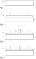
- Figure 1 shows a component 2 as part of a workpiece.
- the component 2 is in Figure 1 shown schematically as a plane-parallel plate.
- the component 2 can of course also take on more complex shapes, for example the shape of a hollow cylinder or a complex machine element.
- the component 2 can be made of glass, plastic, a metal or an alloy, for example.
- the component 2 can be a composite material or consist of a composite material composed of different materials.
- the simplified, purely illustrative representation of the component 2 in Figure 1 is not intended to limit the subject matter of the invention.
- Figure 2 shows the application of a coating 3 in a first partial surface 21 of the component 2.
- the first partial surface 21 can comprise the entire surface of the component 2 or the entire surface of a cavity or an interior space.
- the first partial surface 21 can represent a partial coating of the surface of the component 2, so that other partial surfaces remain uncoated or are coated with other coating material or other coating methods.
- the coating 3 is produced by applying layer-forming substances which are present as an emulsion or solution in a solvent.
- the carrier substance of an emulsion is also referred to as a solvent, even if the layer-forming substances do not chemically dissolve therein, but only emulsify or disperse.
- Non-polar solvents for example aromatic hydrocarbons, or water can be used as solvents.
- the layer-forming substances of the coating 3 can be siloxanes or a silicone oil.
- the solvent is removed from the coating 3, for example by a thermal post-treatment.
- the thermal post-treatment can also crosslink the layer-forming substances with one another and form, for example, a poly(organo)siloxane.
- the heat treatment can create bonding forces between the coating 3 and the workpiece 2, for example in the form of covalent bonds or Van der Waals bonds.
- the application of the coating 3 can be preceded by an optional cleaning step of at least the first partial surface 21.
- the coating 3 can consist of a plurality of individual layers which are applied one above the other.
- Figure 3 shows a subsequent process step.
- the coating 3 or at least a second partial surface 22 of the coating 3 is exposed to a plasma 4. This changes the layer thickness and/or the bonding conditions and/or the Element inventory and/or the wetting behavior of the coating 3 in the second partial surface 22 is changed.
- the plasma 4 can be an atmospheric pressure plasma, so that the use of complex vacuum technology is avoided.
- the plasma 4 can be generated with a dielectrically impeded discharge, which can avoid the introduction of large thermal loads into the second partial surface 22.
- the plasma 4 can contain or consist of an inert gas, for example a noble gas such as argon, helium or xenon.
- the duration of the plasma 4's action can be between about 45 seconds and about 120 seconds.
- the plasma can act for about 0.4 to about 5 seconds, or for about 0.5 to about 4 seconds, or for about 0.5 to about 1.5 seconds, or for about 5 to about 60 seconds. According to the invention, it was recognized that even this short treatment time is sufficient to convert a hydrophobic silicone coating into a hydrophilic, silicon-containing compound, so that the method proposed according to the invention can also be used economically in the manufacture of mass products.
- An embodiment of a plasma source with which the plasma jet of the plasma 4 can be generated is described below with reference to Figure 5 explained in more detail.
- Figure 4 shows the effects of the plasma treatment in the second partial area 22 of the coating 3 or the partial area 22 of the first partial area 21.
- the plasma treatment leads to a reduction in the layer thickness by more than about 20% or more than about 25% or more than about 30%.
- the coating 3 is not completely is removed, but after the plasma treatment a layer thickness of more than about 70% or more than about 60% or more than about 50% remains in the second partial area 22.
- exposure to plasma 4 may cause the elemental inventory of coating 3 to change.
- the carbon content of coating 3 may decrease to less than about 80%, or less than about 75%, or less than about 70%, or less than about 60% of the initial value before plasma treatment.
- the wetting behavior of the second partial surface 22 can change, i.e. the coating 3 can originally be hydrophobic and become hydrophilic after exposure to the plasma 4 in the second partial surface 22.
- the plasma source comprises a high-voltage electrode 52 which is surrounded by an insulator 53.
- the high-voltage electrode 52 is designed as a hollow body and can be cylindrical or conical, for example.
- the insulating body 53 is arranged at a distance from the high-voltage electrode 52. In this way, a working gas can be introduced into the space between the high-voltage electrode 52 and the insulating body 53, which can be supplied via a gas supply 54. The working gas leaves the high-voltage electrode 52 via its substrate-side mouth.
- a counter electrode 51 is arranged opposite the mouth, which can optionally be provided with a dielectric coating. This ensures that a dielectric barrier is always present between the high-voltage electrode 52 and the counter electrode 51. Discharge is ignited. If the substrate itself contains or consists of a dielectric or an insulator, the dielectric coating of the counter electrode 51 can also be omitted.
- a working gas for example argon
- a high-frequency alternating voltage which is generated by a high-voltage source 55, is applied to the high-voltage electrode 52.
- the amplitude of the applied high voltage can be between about 2 kV and about 10 kV or between about 5 kV and about 8 kV.
- the high voltage can be applied as a sinusoidal alternating voltage or in the form of individual high-voltage pulses.
- the pulse repetition frequency or the alternating voltage frequency can be between about 10 Hz and about 30 kHz.
- the power converted in the plasma can be determined by means of a measuring capacitor which integrates the transferred charge carriers of a discharge cycle. The power determined in this way can be between about 0.5 watts and about 5 watts or between about 1 watt and about 3 watts.
- the plasma jet generated in this way has a diameter of approximately 0.15 mm to approximately 0.5 mm.
- the base point widens so that the second partial area 22 can be larger than the diameter of the plasma jet 4.
- a larger second partial area 22 can be processed by sequential treatment with the plasma 4 by moving the component 2 or the counter electrode 51 with the component 2 arranged on it.
- the distance of the beam exit from the surface to be treated can be between approximately 3 mm and approximately 8 mm.
- the layer thickness before exposure to the plasma is 110 nm. After an exposure time of about 10 seconds, the layer thickness already decreases to about 75 nm. After 30 s, the layer thickness is about 57 nm. With a very long treatment time of 300 seconds, the layer thickness decreases to about 50 nm. The layer thickness shows an asymptotic progression with the treatment time. The Figure 6 The measured values shown suggest that the layer thickness does not fall below 50 nm even with longer treatment times.
- the measured values shown were determined using a coating 3 which was obtained by baking siliconization.
- a coating 3 which was obtained by baking siliconization.
- an emulsion of silicone oil and water is applied and then baked onto the surface of component 2 by means of a heat treatment.
- the following table shows the element inventory of the coating 3 before exposure to the plasma, after 1 second, 10 seconds, 30 seconds, 60 seconds and after 300 seconds. All measured values were obtained using photoelectron spectroscopy.
- Monochromatic X-rays are irradiated onto the surface of the coating 3 and the kinetic energy of the photoelectrons is determined.
- the respective element can be determined from the kinetic energy, the intensity of the photoelectrons indicates the relative proportions in the coating 3.
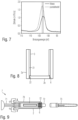
- Figure 11 shows graphically the decrease in carbon content against the treatment duration.
- the treatment duration is shown on the abscissa and the carbon content on the ordinate. This shows that even very short treatment durations of less than one second up to a few seconds can have a significant effect on the coating.
- Such treatment times can be easily achieved, particularly in the production of mass-produced items on an assembly line, without significantly delaying the production of the item. This can significantly improve the adhesive strength of a subsequent coating and/or bonding without having to use wet-chemical processes that are hazardous to health.
- Figure 7 shows the energetic position of the silicon 2p peak.
- the binding energy is plotted on the abscissa and the relative frequency or count rate on the ordinate. It is evident that the position of the silicon 2p level shifts from 102.6 eV to 103.2 eV due to the plasma treatment. The latter value corresponds to the literature value for silicon dioxide (SiO 2 ).
- the polymeric silicon layer obviously changes to an amorphous or glassy layer.
- Figure 8 a first application example of the invention. Shown in Figure 8 the cross section through an approximately cylindrical container with a cylindrical wall 2a, which can be made, for example, from a pipe section.
- the cylindrical wall 2a can be made from glass or plastic.
- a baked-on siliconization is applied as a coating 3 to the inside of the cylindrical wall 2a, as described above.
- a solution or an emulsion of a silicone oil and a solvent is applied and then baked by treatment in a heating oven at about 150°C to about 300°C.
- the coating 3 has hydrophobic properties, so that the adhesive strength of subsequent adhesive bonds is impaired.
- a second component 2b is to be joined to the first component 2a.
- the second component 2b can be a base plate shaped to complement the cylindrical wall 2a, which seals the resulting container fluid-tight at the bottom.
- the base plate 2b is to be attached and sealed by means of an adhesive connection 6.
- a second partial surface 22 is exposed to an atmospheric pressure plasma, as described above. On the one hand, this leads to a reduction in the layer thickness of the coating 3. At the same time, the chemical composition and the element inventory of the coating 3 change. After completion of the plasma treatment, the second partial surface 22 is hydrophilic. This ensures good adhesion of the adhesive bond 6.
- the component 2b in Figure 8 without coating 3 it is of course not excluded that the component 2b is also provided with a coating before joining, which can also be applied by baking siliconization.
- the adhesive surface of the component 2b can also be subsequently subjected to a plasma treatment in order to improve the adhesive strength or to enable an adhesive connection in the first place.
- Figure 9 shows a pre-filled syringe as a second embodiment of the invention.
- the pre-filled syringe 7 has an approximately cylindrical syringe body 70.
- the body 70 represents a first component 2.
- Pre-filled syringes 7 of the type shown serve as packaging for the medication contained therein in the manufacturing plant, so that it can be handed over to the doctor or patient immediately ready for use.
- the syringe body 70 is first made from a glass tube
- the glass tube is cut, heated and formed into the desired shape.
- the inside is sprayed with an emulsion of a solvent and layer-forming substances and then treated in an oven or heating cabinet.
- This causes a large part of the solvent present in the emulsion to evaporate.
- the silicone contained as a layer-forming substance is covalently bound to the glass, so that a coating 3 is formed on the inside, which contains or consists of polysiloxane.
- the heat treatment prevents the silicone from undesirably migrating into the medication during later filling, storage and use of the pre-filled syringe 7.
- the siliconization allows the piston 7 to slide easily, making handling of the pre-filled syringe 7 easier.
- a cone 72 is glued to the end of the syringe body 70 opposite the piston 71, which is intended to accommodate the injection needle 73.
- the injection needle 73 can also be glued directly into the syringe body 70, so that the cone 72 can also be omitted.
- the coating 3 also covers the second partial surface 22 intended to accommodate the cone 72, the adhesive strength of an adhesive connection 6 is reduced. This can go so far that the cone 72 falls out of the syringe body 70 during transport or storage and the contents of the prefilled syringe 7 leak out.
- the hydrophobic coating 3 in the second partial surface 22 can become hydrophilic in order to improve the adhesive strength of the bond 6.
- the pre-filled syringe 7 is prepared for filling in a manner known per se, i.e. cleaned, sterilized and packaged.
- the syringe prepared for filling in this way is then delivered to the manufacturer of the medication for filling.
- Figure 10 shows the cross-section through a blister pack 8.
- the blister pack contains a first film layer 81 in which cavities 83 are formed.
- the first film layer 81 can be formed from aluminum foil or plastic.
- At least the inside of the cavities 83 is provided with a baked-on siliconization as a coating 3, as explained above. This prevents the packaged goods from sticking during later use of the blister pack 8 and at the same time prevents the undesired transfer of the silicone oil onto the packaged goods.
- first film layer 81 of the blister pack is completely siliconized, this prevents reliable bonding with a second film layer 82, which is necessary to close the cavities 83 after the packaged goods have been inserted. Therefore, second partial surfaces 22 lying between the cavities are treated with a plasma in the manner described in order to inactivate the coating 3 and to convert it from a hydrophobic to a hydrophilic state.
- the Cavities 83 can be reliably closed by gluing a second, flat film layer 82 onto the first film layer 81.
- Figure 12 shows a workpiece according to a fourth embodiment of the invention.
- the fourth embodiment is also a pre-filled syringe, the basic function of which has already been explained using the second embodiment.
- the same components are provided with the same reference numerals, so that the following description is limited to the essential differences.
- the syringe body 70 is first made from a glass tube. To do this, the glass tube is cut to size, heated and formed into the desired shape.
- the syringe body 70 can also be made from plastic. Plastic syringes are manufactured using known manufacturing processes, e.g. injection molding.
- the inside of the syringe body 70 is sprayed with an emulsion of a solvent and layer-forming substances and then treated in an oven, e.g. a tunnel oven or heating cabinet.
- an oven e.g. a tunnel oven or heating cabinet.
- the silicone contained as a layer-forming substance is largely covalently bound to the glass, so that a coating 3 is formed on the inside, which contains or consists of polysiloxane and/or polydimethylsiloxane.
- the heat treatment prevents the silicone from undesirably migrating into the medication during later filling, storage and use of the pre-filled syringe 7.
- the siliconization allows the piston stopper 75 to slide easily, so that the handling of the pre-filled syringe 7 or a Application of the medication is made easier or even possible in the first place.
- a cannula 76 is glued to the end of the syringe body 70 opposite the piston stopper 75.
- the coating 3 also covers the second partial surface 22 intended to accommodate the cannula 76, the adhesive strength of an adhesive connection 6 is reduced. This can go so far that the cannula 76 falls out of the syringe body 70 during transport or storage and the contents of the prefilled syringe 7 leak out.
- the hydrophobic coating 3 in the second partial surface can become hydrophilic and thus improve the adhesive strength of the adhesive connection 6.
- the pre-filled syringe 7 is prepared for filling in a manner known per se, i.e. cleaned, sterilized and packaged.
- the needle protection part 74 is also placed on the cannula 76.
- the syringe prepared for filling in this way is then delivered to the manufacturer of the medication for filling.
Landscapes
- Engineering & Computer Science (AREA)
- Physics & Mathematics (AREA)
- Plasma & Fusion (AREA)
- Health & Medical Sciences (AREA)
- Mechanical Engineering (AREA)
- Chemical & Material Sciences (AREA)
- Organic Chemistry (AREA)
- Anesthesiology (AREA)
- Vascular Medicine (AREA)
- Biomedical Technology (AREA)
- Heart & Thoracic Surgery (AREA)
- Hematology (AREA)
- Life Sciences & Earth Sciences (AREA)
- Animal Behavior & Ethology (AREA)
- General Health & Medical Sciences (AREA)
- Public Health (AREA)
- Veterinary Medicine (AREA)
- Application Of Or Painting With Fluid Materials (AREA)
Description
- Die Erfindung betrifft ein Verfahren zur Beschichtung, bei welchem zumindest auf eine erste Teilfläche einer Oberfläche eines Bauteils zumindest eine Emulsion und/oder eine Lösung aufgebracht wird, welche zumindest eine schichtbildende Substanz enthält, und nachfolgend das Bauteil wärmebehandelt wird. Weiterhin betrifft die Erfindung ein Verfahren, bei welchem zumindest ein solches Bauteil mit zumindest einem weiteren Bauteil gefügt wird. Schließlich betrifft die Erfindung ein solchermaßen erhaltenes Werkstück.
- Ein gattungsgemäßes Verfahren ist beispielsweise aus der
EP 1 352 667 A1 bekannt. Dieses Dokument beschreibt ein Verfahren zum Herstellen einer Injektionsspritze, bei welchem der Spritzenkörper bei hoher Temperatur innen mit einem Gleitmittel versehen wird. An der Fügestelle zwischen Spritzenkörper und Kanüle wird das Gleitmittel darauffolgend wieder entfernt, um eine zuverlässige Haftung des zum Fügen verwendeten Klebstoffes zu ermöglichen. - Dieses bekannte Verfahren weist den Nachteil auf, dass das vollständige Entfernen des Gleitmittels in einem räumlich eng begrenzten Bereich nur mit großem Aufwand erreicht werden kann. Ausgehend von diesem bekannten Verfahren liegt der Erfindung somit die Aufgabe zugrunde, zumindest eine Teilfläche einer Beschichtung in einfacher Weise für eine nachfolgende Klebeverbindung oder auch ein weiteres Beschichtungsverfahren vorzubereiten.
- Aus der
WO 2016/124824 A1 ist ein Verfahren zum Einkapseln einer Verglasung in Polycarbonat bekannt. Das Verfahren umfasst die folgenden aufeinanderfolgenden Schritte: - (a) Behandeln eines Bereichs der Oberfläche der Verglasung, der eine harte Beschichtung auf Silikonbasis trägt, mit atmosphärischem Plasma unter Verwendung einer Plasmadüse
- (b) Auftragen einer primären Zusammensetzung, umfassend einen oder mehrere Haftvermittler, ausgewählt aus Diisocyanaten, Polyisocyanaten und chloriertem Polyolefin,
- (c) Verdampfen des Lösungsmittels und
- (d) Überformen eines thermoplastischen Polymers auf dem Bereich, der von der trockenen Grundierungsschicht bedeckt ist.
- Die
WO 99/57185 A1 -
US 4,524,089 A1 zeigt eine dreistufige Plasmabehandlung zur Verbesserung der Laminathaftung von metallischen und nichtmetallischen Substraten. Die Behandlung umfasst das aufeinanderfolgende Aussetzen des Substrats einem ersten Plasma aus Sauerstoffgas, einem zweiten Plasma aus einem Kohlenwasserstoffmonomergas und einem dritten Plasma aus Sauerstoffgas. - Aus der
JP H03 41176 A - Die
FR 2 840 826 A1 -
US 2010/304156 A1 offenbart ein Fügeverfahren mit folgenden Schritten: Vorbereiten eines ersten Grundmaterials und eines zweiten Grundmaterials, die über einen Verbindungsfilm miteinander verbunden werden sollen; Bilden einer flüssigen Beschichtung durch Auftragen eines flüssigen Materials, das ein Polyester-modifiziertes Silikonmaterial enthält, auf mindestens eines der Grundmaterialien; Trocknen und/oder Härten der flüssigen Beschichtung, um den Verbindungsfilm zu erhalten; Behandeln des Verbindungsfilms mit einem Plasma und Inkontaktbringen des ersten Grundmaterials und des zweiten Grundmaterials über den Verbindungsfilm. - Die Aufgabe wird erfindungsgemäß durch ein Verfahren gemäß Anspruch 1 und ein Werkstück nach Anspruch 10 gelöst. Vorteilhafte Weiterbildungen der Erfindung finden sich in den Unteransprüchen.
- Erfindungsgemäß wird ein Verfahren zur Beschichtung vorgeschlagen, bei welchem zumindest auf eine Teilfläche einer Oberfläche eines Bauteils zumindest eine Emulsion und/oder eine Lösung aufgebracht wird, welche zumindest eine schichtbildende Substanz enthält. Das Bauteil kann in einigen Ausführungsformen der Erfindung aus Glas, Kunststoff, einem Metall oder einer Legierung gefertigt sein. Das Bauteil weist eine gekrümmte Oberfläche auf.
- Insbesondere ist das Bauteil eine Hohlform, deren Innenfläche mit einer Beschichtung versehen wird. Das Bauteil kann in einigen Ausführungsformen der Erfindung ein Halbzeug sein, welches in nachfolgenden Verfahrensschritten zu einem Fertigprodukt weiterbearbeitet wird. In anderen Ausführungsformen der Erfindung kann das Bauteil auch ein Fertigprodukt sein, welches nach Durchführung des vorgeschlagenen Beschichtungsverfahrens keiner weiteren Bearbeitung mehr bedarf.
- Die Beschichtung enthält zumindest eine schichtbildende Substanz, welche in Form einer Emulsion und/oder einer Lösung vorliegt. Die Emulsion oder die Lösung enthält neben der schichtbildenden Substanz zumindest ein Lösemittel. Für die Zwecke der vorliegenden Beschreibung wird die Trägermatrix einer Emulsion ebenfalls als ,Lösemittel' bezeichnet, auch wenn die Schichtbildenden Substanzen nur emulgiert und nicht im strengeren Sinne gelöst sind.
- Die Emulsion oder die Lösung kann durch an sich bekannte Verfahren auf zumindest eine erste Teilfläche des Bauteils aufgebracht werden. In einigen Ausführungsformen der Erfindung kann auch eine Vollbeschichtung des Bauteils vorgesehen sein, d.h. die gesamte Oberfläche des Bauteils wird erfindungsgemäß beschichtet. Die Emulsion oder die Lösung kann beispielsweise durch Sprühen, Drucken, Streichen oder Tauchen aufgebracht werden. Um eine gleichmäßigere Beschichtung mit der Emulsion bzw. der Lösung zu ermöglichen, können zusätzliche Maßnahmen ergriffen werden, beispielsweise das Herabsetzen der Viskosität durch Erwärmen und/oder Verdünnen oder eine Unterstützung der Beschichtung durch elektrische Felder ähnlich einer Elektrotauchlackierung.
- Erfindungsgemäß wird das Bauteil nach dem Aufbringen der Emulsion bzw. der Lösung wärmebehandelt. Die Wärmebehandlung kann unmittelbar nach dem Aufbringen der Emulsion bzw. der Lösung erfolgen. In anderen Ausführungsformen der Erfindung kann die Wärmebehandlung nach einem vorangegangenen Trocknungsschritt durchgeführt werden. Die Wärmebehandlung führt einerseits dazu, dass das Lösungsmittel der Emulsion bzw. der Lösung verdampft bzw. aus der Schicht ausgetrieben wird. Darüber hinaus kann eine Verbindung zwischen den schichtbildenden Substanzen und der Oberfläche des Bauteils entstehen, beispielsweise durch kovalente Bindungen oder Van-der-Waals-Bindungen. In einigen Ausführungsformen der Erfindung können die schichtbildenden Substanzen auch untereinander vernetzt sein und beispielsweise ein Polymer oder eine polymerartige Verbindung ausbilden.
- In einigen Ausführungsformen der Erfindung ist die auf diese Weise erzeugte Beschichtung hydrophob und/oder weist gegenüber der unbehandelten Oberfläche verbesserte Gleiteigenschaften auf. In einigen Ausführungsformen der Erfindung kann die erzeugte Beschichtung auch chemisch inert gegenüber Gasen oder Flüssigkeiten sein, mit welchen das Bauteil bei bestimmungsgemäßem Gebrauch in Kontakt kommt.
- In einem nachfolgenden Verfahrensschritt wird zumindest eine zweite Teilfläche der mit der Beschichtung versehenen ersten Teilfläche des Bauteils einer Plasmabehandlung unterzogen, um auf diese Weise die Wirkungen der Beschichtung zumindest teilweise zu deaktivieren bzw. rückgängig zu machen, ohne die Beschichtung als solche vollständig zu entfernen. Unter einem Plasma im Sinne der vorliegenden Beschreibung wird ein teilweise ionisiertes Gas verstanden, welches bei einem vorgebbaren Druck und mit vorgebbarer Zusammensetzung für eine bestimmte Zeitdauer auf zumindest eine zweite Teilfläche der Beschichtung einwirkt. In einigen Ausführungsformen der Erfindung kann die zweite Teilfläche ebenso groß sein wie die beschichtete erste Teilfläche, sodass das Plasma auf die gesamte vorher aufgebrachte Beschichtung einwirkt. Sofern die erste Teilfläche die gesamte Oberfläche des Bauteils umfasst, kann das Plasma auch auf die gesamte Oberfläche des Bauteils einwirken. In anderen Ausführungsformen der Erfindung wird nur ein Teil der Beschichtung der Plasmabehandlung unterworfen, wohingegen andere Teile der Beschichtung nicht dem Plasma ausgesetzt werden. Beispielsweise können Teilflächen der Plasmabehandlung unterzogen werden, welche in einem weiteren Verfahrensschritt eine Fügestelle ausbilden sollen, um auf diese Weise die Haftung von Klebstoffen oder Lot zu verbessern oder überhaupt erst zu ermöglichen.
- Durch die Einwirkung des Plasmas reduziert sich der Kohlenstoffgehalt der Beschichtung auf weniger als etwa 80% oder weniger als etwa 75% oder weniger als etwa 70% oder weniger als etwa 60% des Ausgangswertes vor der Plasmabehandlung. Die Reduktion des Kohlenstoffgehaltes kann darüber hinaus auch die Wirkung haben, dass sich die Bindungen innerhalb der Beschichtung ändern. Beispielsweise kann die Beschichtung von einer polymeren Struktur in eine glasartige oder amorphe Struktur umgewandelt werden.
- Schließlich kann durch die Einwirkung des Plasmas die Schichtdicke in der behandelten zweiten Teilfläche abnehmen. In einigen Ausführungsformen der Erfindung kann die Schichtdicke um mehr als etwa 20% oder mehr als etwa 25 % oder mehr als etwa 30 % reduziert werden.
- Erfindungsgemäß wurde jedoch erkannt, dass die Beschichtung durch die Einwirkung des Plasmas nicht vollständig entfernt wird. Vielmehr kann nach der Plasmabehandlung in der zweiten Teilfläche eine Schichtdicke von mehr als etwa 70% oder mehr als etwa 60 % oder mehr als etwa 50 % der im ersten Verfahrensschritt aufgebrachten Schichtdicke verbleiben.
- Zusammenfassend kann festgehalten werden, dass durch die Plasmabehandlung die Bindungsverhältnisse und/oder die Schichtdicke und/oder das Elementinventar der ursprünglich aufgebrachten Beschichtung in der dem Plasma ausgesetzten Teilfläche verändert werden. Hierdurch kann eine Aufrauung der Beschichtung und/oder eine Hydrophilierung eintreten, sodass ein nachfolgendes Beschichtungs- oder Fügeverfahren erleichtert oder überhaupt erst ermöglicht wird. Gleichzeitig kann die Plasmabehandlung einfacher durchzuführen sein als eine vollständige Entfernung der Beschichtung, welche unter Umständen sehr stark an der Oberfläche des Bauteils haftet und nur mechanisch oder nasschemisch entfernt werden kann, wobei einerseits die entstehende Umweltbelastung erfindungsgemäß vermieden werden kann und andererseits aufwendige Maßnahmen zur Beschränkung des Zutritts eines flüssigen oder gasförmigen Ätzmediums außerhalb der zu behandelnden zweiten Teilflächen vermieden werden kann.
- In einigen Ausführungsformen der Erfindung beträgt die Schichtdicke der Beschichtung zumindest in der zweiten Teilfläche vor der Einwirkung des Plasmas zwischen etwa 20 nm und etwa 100 nm oder zwischen etwa 30 nm und etwa 70 nm. Eine solche Beschichtung beeinträchtigt die Maßhaltigkeit des beschichteten Bauteils nicht, kann jedoch bereits ausreichen, um verbesserte Gleiteigenschaften, eine Hydrophobierung und/oder eine Passivierung der Oberfläche zu bewirken.
- In einigen Ausführungsformen der Erfindung kann die Emulsion und/oder die Lösung zumindest ein Silikonöl und ein Lösungsmittel enthalten oder daraus bestehen. In einigen Ausführungsformen der Erfindung kann das Lösungsmittel Wasser sein oder Wasser enthalten. In anderen Ausführungsformen der Erfindung kann das Lösungsmittel aliphatische Kohlenwasserstoffe oder Aromaten enthalten, beispielsweise Hexan, Heptan, Toluol und/oder Xylol. Schließlich kann das Lösungsmittel zur Bildung einer Emulsion auch einen Alkohol und/oder Glyzerin und/oder Äther enthalten. In jedem Fall kann das Lösungsmittel entweder bei normalen Umgebungsbedingungen oder bei erhöhter Temperatur im Wärmeschrank oder Ofen verdampft bzw. aus der entstehenden Beschichtung ausgetrieben werden, sodass eine Beschichtung auf der ersten Teilfläche des Bauteils verbleibt, welche Silikon enthält oder daraus besteht.
- Die Beschichtung kann in einigen Ausführungsformen der Erfindung zumindest Kohlenstoff und Sauerstoff und Wasserstoff und Silizium enthalten. In einigen Ausführungsformen der Erfindung kann die Beschichtung zumindest ein Polyorganosiloxan enthalten oder daraus bestehen. Durch die Einwirkung des Plasmas kann der Kohlenstoff aus der Beschichtung zumindest teilweise entfernt werden, sodass die Beschichtung nach der Plasmabehandlung Siliziumoxid und/oder Siliziumnitrid und/oder Siliziumoxinitrid enthält oder daraus besteht.
- In einigen Ausführungsformen der Erfindung ist die zweite Teilfläche vor der Plasmabehandlung hydrophob und nach der Plasmabehandlung hydrophil. In anderen Ausführungsformen der Erfindung ist die zweite Teilfläche vor der Plasmabehandlung hydrophil und nach der Plasmabehandlung hydrophob. Unter einer hydrophoben Beschichtung wird für die Zwecke der vorliegenden Beschreibung eine Oberfläche verstanden, welche bei Kontakt mit Wasser einen Kontaktwinkel von mehr als 90° ausbildet. Eine hydrophile Oberfläche ist für die Zwecke der vorliegenden Beschreibung eine Oberfläche, welche bei Benetzung mit Wasser einen Kontaktwinkel von weniger als 90° ausbildet. Durch die Plasmabehandlung kann die Oberflächenenergie daher soweit geändert werden, dass die Haftfestigkeit bzw. die Benetzbarkeit mit einem Schmiermittel, einem Klebstoff, einem Lot oder einem Lack ansteigt bzw. überhaupt erst ermöglicht wird.
- In einigen Ausführungsformen der Erfindung kann das Plasma (4) für etwa 0,4 bis etwa 5 Sekunden oder für etwa 0,5 bis etwa 4 Sekunden oder für etwa 0,5 bis etwa 1,5 Sekunden oder für etwa 5 bis etwa 60 Sekunden einwirken. Erfindungsgemäß wurde erkannt, dass diese kurze Behandlungsdauer bereits ausreicht, um eine hydrophobe Silikonbeschichtung in eine hydrophile, siliziumhaltige Verbindung umzusetzen, sodass das erfindungsgemäß vorgeschlagene Verfahren auch bei der Herstellung von Massenprodukten wirtschaftlich eingesetzt werden kann.
- In einigen Ausführungsformen der Erfindung kann ein Atmosphärendruckplasma zum Einsatz kommen, welches mit einer dielektrisch behinderten Entladung erzeugt wird. Dieses Merkmal hat die Wirkung, dass auf eine aufwendige Vakuumtechnik verzichtet werden kann und das Verfahren auf diese Weise leicht in bestehende Produktionsprozesse integriert werden kann. Die Verwendung einer dielektrisch behinderten Entladung sorgt dabei dafür, dass die in das Plasma eingekoppelte elektrische Leistung begrenzt bleibt und thermische Schäden des Bauteils und/oder der Beschichtung vermieden werden können.
- Erfindungsgemäß kommt zur Erzeugung des Plasmas eine Wirbelströmung des Arbeitsgases zum Einsatz. Dadurch kann die Entladung in die Länge gezogen werden. Insbesondere die Behandlung der Innenflächen zylindrischer Hohlkörper verstärkt diesen Effekt noch, da die Oberflächen die Entladung unterstützen. Dadurch können auch schlanke Gegenstände wie Rohre oder Spritzen behandelt werden.
- In einigen Ausführungsformen der Erfindung kann das Plasma ein Inertgas enthalten oder daraus bestehen. In einigen Ausführungsformen der Erfindung kann das Inertgas ein Edelgas sein oder ein solches enthalten. In einigen Ausführungsformen der Erfindung kann das Plasma Argon enthalten oder daraus bestehen. Ein Inertgasplasma sorgt insbesondere dafür, dass die Bestandteile der Beschichtung nicht oxidiert oder reduziert werden oder anderweitig mit dem Prozessgas des Plasmas reagieren, so dass sich die Beschichtung nicht in unerwünschter Weise umsetzt oder durch reaktives Ätzen von der Oberfläche entfernt wird.
- In einigen Ausführungsformen der Erfindung kann das Plasma ein Aktivgas sein, welches beispielsweise Stickstoff und/oder Sauerstoff enthält oder daraus besteht.
- In einigen Ausführungsformen der Erfindung kann das Plasma durch eine Wechselspannung oder eine gepulste Spannung erzeugt werden, welche eine Frequenz zwischen etwa 10 kHz und etwa 30 kHz oder zwischen etwa 15 kHz und etwa 25 kHz aufweist.
- In einigen Ausführungsformen der Erfindung kann ein Plasmastrahl verwendet werden, welcher durch ein elektrisches Feld zwischen der Oberfläche des Bauteils und zumindest einer Gegenelektrode durch Ionisieren eines Arbeitsgasstromes erzeugt wird. In anderen Ausführungsformen der Erfindung kann ein Plasmajet verwendet werden. In diesem Fall wird das Plasma im Inneren der Plasmaquelle durch elektrische Felder oder elektromagnetische Strahlung erzeugt und vom Arbeitsgasstrom aus der Quelle ausgetrieben. In einigen Ausführungsformen der Erfindung wird das Plasma mit einer dielektrisch behinderten Entladung erzeugt. Solchermaßen erzeugte Plasmen weisen nur geringe Temperaturerhöhungen von weniger als etwa 50 K oder weniger als etwa 30 K gegenüber der Umgebung auf, sodass thermische Schäden auch bei empfindlichen Oberflächen vermieden werden können. Dies ist beispielsweise bei der Behandlung von Bauteilen aus einem Polymer oder anderen Kunststoffen hilfreich.
- In einigen Ausführungsformen der Erfindung betrifft diese ein Verfahren zur Herstellung eines Werkstückes mit zumindest einem ersten Bauteil und zumindest einem zweiten Bauteil, welche miteinander gefügt werden. Dabei wird zumindest ein Bauteil zunächst wie vorstehend beschrieben beschichtet und sodann zumindest die zur Ausbildung der Fügestelle vorgesehene zweite Teilfläche mit dem erfindungsgemäßen Plasma behandelt, um die Beschichtung in der Teilfläche wie beschrieben zu verändern. Auf diese Weise wird die Haftung eines Lotes oder eines Klebstoffes verbessert, sodass die Fügestelle eine verbesserte Dichtigkeit und/oder größere Haftfestigkeiten aufweist.
- In einigen Ausführungsformen der Erfindung kann das Fügen unter Verwendung eines Klebstoffes erfolgen, welcher insbesondere ausgewählt ist aus einem Acrylat und/oder Polyurethan und/oder einem Epoxidharz und/oder einem Cyanacrylat. Solche Klebstoffe weisen hohe Haftfestigkeiten bei einfacher Verarbeitbarkeit und hohen Anfangsfestigkeiten auf, sodass die Produktion des Werkstückes rasch vorgenommen werden kann.
- In einigen Ausführungsformen der Erfindung betrifft diese ein Werkstück, welches zumindest ein erstes Bauteil und zumindest ein zweites Bauteil umfasst, welche durch Kleben miteinander gefügt sind, wobei die Fügestelle zumindest eine zweite Teilfläche einer ersten Teilfläche der Oberfläche des ersten Bauteils umfasst, wobei zumindest auf der ersten Teilfläche der Oberfläche des ersten Bauteils zumindest eine Beschichtung aufgebracht ist. Zumindest die zweite Teilfläche der beschichteten ersten Teilfläche wurde nachfolgend einem Plasma ausgesetzt, wodurch der Kohlenstoffgehalt der Beschichtung reduziert und/oder die Bindungsverhältnisse der Beschichtung geändert und/oder die Schichtdicke reduziert wurde. Die beschriebenen Veränderungen können eine Erhöhung der Haftfestigkeit der Klebeverbindung bewirken, sodass die Zuverlässigkeit des Werkstückes erhöht sein kann. Das Werkstück kann ein fertiges Produkt oder ein Halbzeug sein, welches in nachfolgenden Verfahrensschritten weiter bearbeitet wird.
- Erfindungsgemäß ist der Kohlenstoffgehalt der Beschichtung in der zweiten Teilfläche der Beschichtung (3) auf weniger als etwa 80% oder weniger als etwa 75% oder weniger als etwa 70% oder weniger als etwa 60% des Ausgangswertes vor der Plasmabehandlung reduziert.
- Das Werkstück kann in einigen Ausführungsformen der Erfindung ausgewählt sein aus einer Fertigspritze und/oder einer Verpackung und/oder einer Maschinenkomponente. Eine Maschinenkomponente kann beispielsweise ein Gehäuse sein, welches andere Komponenten umgibt. Zumindest das erste und/oder das zweite Bauteil des Werkstücks kann aus einem Kunststoff, einem Glas, einem Metall oder einer Legierung gefertigt sein.
- Nachfolgend soll die Erfindung anhand von Figuren ohne Beschränkung des allgemeinen Erfindungsgedankens näher erläutert werden. Dabei zeigt
- Figur 1
- ein zur Beschichtung vorgesehenes Bauteil.
- Figur 2
- zeigt ein Bauteil mit aufgebrachter Beschichtung.
- Figur 3
- erläutert die Plasmabehandlung einer Teilfläche des Bauteils.
- Figur 4
- zeigt das Bauteil nach erfolgter Plasmabehandlung.
- Figur 5
- zeigt eine Plasmaquelle, welche mit dem vorgeschlagenen Verfahren verwendbar ist.
- Figur 6
- zeigt in einem Ausführungsbeispiel die Schichtdickenabnahme über die Behandlungszeit.
- Figur 7
- zeigt Messergebnisse der Photoelektronenspektroskopie an einer erfindungsgemäßen Beschichtung.
- Figur 8
- zeigt ein Werkstück gemäß einer ersten Ausführungsform der Erfindung.
- Figur 9
- zeigt ein Werkstück gemäß einer zweiten Ausführungsform der Erfindung.
- Figur 10
- zeigt ein Werkstück gemäß einer dritten Ausführungsform der Erfindung.
- Figur 11
- zeigt die Abnahme des Kohlenstoffgehaltes gegen die Behandlungsdauer.
- Figur 12
- zeigt ein Werkstück gemäß einer vierten Ausführungsform der Erfindung.
-
Figur 1 zeigt ein Bauteil 2 als Teil eines Werkstückes. Das Bauteil 2 ist inFigur 1 schematisch als planparallele Platte dargestellt. In anderen Ausführungsformen der Erfindung kann das Bauteil 2 selbstverständlich auch komplexere Formen annehmen, beispielsweise die Form eines Hohlzylinders oder eines komplexen Maschinenelementes. - Das Bauteil 2 kann beispielsweise aus Glas, Kunststoff, einem Metall oder einer Legierung gefertigt sein. Das Bauteil 2 kann in einigen Ausführungsformen der Erfindung ein Kompositmaterial sein bzw. daraus bestehen, welches aus verschiedenen Materialien zusammengesetzt ist. Die vereinfachte, rein illustrative Darstellung des Bauteils 2 in
Figur 1 soll den Gegenstand der Erfindung nicht beschränken. -
Figur 2 zeigt das Aufbringen einer Beschichtung 3 in einer ersten Teilfläche 21 des Bauteils 2. In einigen Ausführungsformen der Erfindung kann die erste Teilfläche 21 die gesamte Oberfläche des Bauteils 2 umfassen oder die gesamte Fläche einer Kavität oder eines Innenraumes. In anderen Ausführungsformen der Erfindung kann die erste Teilfläche 21 eine Teilbeschichtung der Oberfläche des Bauteils 2 darstellen, so dass andere Teilflächen unbeschichtet bleiben oder mit anderem Beschichtungsmaterial oder anderen Beschichtungsverfahren beschichtet werden. - Die Beschichtung 3 wird durch Aufbringen schichtbildender Substanzen erzeugt, welche als Emulsion oder Lösung in einem Lösungsmittel vorliegen. Für die Zwecke der vorliegenden Beschreibung soll auch die Trägersubstanz einer Emulsion als Lösungsmittel bezeichnet werden, auch wenn sich die schichtbildenden Substanzen darin nicht chemisch lösen, sondern nur emulgieren bzw. dispergieren.
- Als Lösungsmittel können nichtpolare Lösungsmittel, beispielsweise aromatische Kohlenwasserstoffe, Verwendung finden oder auch Wasser. Die schichtbildenden Substanzen der Beschichtung 3 können in einigen Ausführungsformen der Erfindung Siloxane oder ein Silikonöl sein.
- Nach Aufbringen der Emulsion bzw. der Lösung durch Aufrakeln, Tauchen, Sprühen, Streichen oder Drucken wird das Lösungsmittel beispielsweise durch eine thermische Nachbehandlung aus der Beschichtung 3 entfernt. Durch die thermische Nachbehandlung können die schichtbildenden Substanzen darüber hinaus miteinander vernetzen und beispielsweise ein Poly(organo)siloxan bilden. Darüber hinaus können durch die Wärmebehandlung Bindungskräfte zwischen der Beschichtung 3 und dem Werkstück 2 ausgebildet werden, beispielsweise in Form kovalenter Bindungen oder Van-der-Waals-Bindungen. Dem Aufbringen der Beschichtung 3 kann ein optionaler Reinigungsschritt zumindest der ersten Teilfläche 21 vorausgehen. In anderen Ausführungsformen der Erfindung kann die Beschichtung 3 aus einer Mehrzahl von Einzelschichten bestehen, welche übereinander aufgebracht werden.
-
Figur 3 zeigt einen nachfolgenden Verfahrensschritt. In diesem Verfahrensschritt wird die Beschichtung 3 bzw. zumindest eine zweite Teilfläche 22 der Beschichtung 3 einem Plasma 4 ausgesetzt. Hierdurch wird die Schichtdicke und/oder die Bindungsverhältnisse und/oder das Elementinventar und/oder das Benetzungsverhalten der Beschichtung 3 in der zweiten Teilfläche 22 verändert. - Das Plasma 4 kann in einigen Ausführungsformen der Erfindung ein Atmosphärendruckplasma sein, sodass die Verwendung aufwendiger Vakuumtechnik vermieden wird. In einigen Ausführungsformen der Erfindung kann das Plasma 4 mit einer dielektrisch behinderten Entladung erzeugt werden, welche das Einbringen großer thermischer Lasten in die zweite Teilfläche 22 vermeiden kann. Das Plasma 4 kann in einigen Ausführungsformen der Erfindung ein Inertgas enthalten bzw. daraus bestehen, beispielsweise ein Edelgas wie Argon, Helium oder Xenon.
- Die Einwirkdauer des Plasmas 4 kann in einigen Ausführungsformen der Erfindung zwischen etwa 45 Sekunden und etwa 120 Sekunden betragen. In anderen Ausführungsformen der Erfindung kann das Plasma für etwa 0,4 bis etwa 5 Sekunden oder für etwa 0,5 bis etwa 4 Sekunden oder für etwa 0,5 bis etwa 1,5 Sekunden oder für etwa 5 bis etwa 60 Sekunden einwirken. Erfindungsgemäß wurde erkannt, dass auch diese kurze Behandlungsdauer bereits ausreicht, um eine hydrophobe Silikonbeschichtung in eine hydrophile, siliziumhaltige Verbindung umzusetzen, sodass das erfindungsgemäß vorgeschlagene Verfahren auch bei der Herstellung von Massenprodukten wirtschaftlich eingesetzt werden kann. Ein Ausführungsbeispiel einer Plasmaquelle, mit welcher der Plasmastrahl des Plasmas 4 erzeugbar ist, wird nachfolgend anhand von
Figur 5 näher erläutert. -
Figur 4 zeigt die Auswirkungen der Plasmabehandlung in der zweiten Teilfläche 22 der Beschichtung 3 bzw. der Teilfläche 22 der ersten Teilfläche 21. Wie inFigur 4 dargestellt ist, führt die Plasmabehandlung zu einer Reduktion der Schichtdicke um mehr als etwa 20% oder mehr als etwa 25 % oder mehr als etwa 30 %. Es ist jedoch darauf hinzuweisen, dass die Beschichtung 3 nicht vollständig entfernt wird, sondern nach der Plasmabehandlung in der zweiten Teilfläche 22 eine Schichtdicke von mehr als etwa 70% oder mehr als etwa 60 % oder mehr als etwa 50 % verbleibt. - Darüber hinaus kann die Einwirkung des Plasmas 4 dazu führen, dass sich das Elementinventar der Beschichtung 3 ändert. Beispielsweise kann der Kohlenstoffgehalt der Beschichtung 3 auf weniger als etwa 80% oder weniger als etwa 75% oder weniger als etwa 70% oder weniger als etwa 60% des Ausgangswertes vor der Plasmabehandlung abnehmen.
- Schließlich kann sich in einigen Ausführungsformen der Erfindung das Benetzungsverhalten der zweiten Teilfläche 22 ändern, d. h. die Beschichtung 3 kann ursprünglich hydrophob sein und nach Einwirkung des Plasmas 4 in der zweiten Teilfläche 22 hydrophil werden.
- Anhand von
Figur 5 wird eine Plasmaquelle näher erläutert, welche zur Durchführung des vorstehend beschriebenen Beschichtungsverfahrens geeignet ist. Die Plasmaquelle umfasst eine Hochspannungselektrode 52, welche von einem Isolator 53 umgeben ist. Die Hochspannungselektrode 52 ist als Hohlkörper ausgebildet und kann beispielsweise zylindrisch oder konisch sein. Der Isolierkörper 53 ist von der Hochspannungselektrode 52 beabstandet angeordnet. Auf diese Weise kann ein Arbeitsgas in den Zwischenraum zwischen der Hochspannungselektrode 52 und dem Isolierkörper 53 eingeführt werden, welches über eine Gaszufuhr 54 zugeführt werden kann. Das Arbeitsgas verlässt die Hochspannungselektrode 52 über deren substratseitige Mündung. - Der Mündung gegenüberliegend ist eine Gegenelektrode 51 angeordnet, welche optional mit einer dielektrischen Beschichtung versehen sein kann. Hierdurch wird sichergestellt, dass zwischen der Hochspannungselektrode 52 und der Gegenelektrode 51 in jedem Fall eine dielektrisch behinderte Entladung gezündet wird. Sofern das Substrat selbst ein Dielektrikum bzw. einen Isolator enthält oder daraus besteht, kann die dielektrische Beschichtung der Gegenelektrode 51 auch entfallen.
- Bei Betrieb der Vorrichtung wird über die Gaszufuhr 54 ein Arbeitsgas, beispielsweise Argon, zugeführt. An die Hochspannungselektrode 52 wird eine hochfrequente Wechselspannung angelegt, welche mit einer Hochspannungsquelle 55 erzeugt wird. In einigen Ausführungsformen der Erfindung kann die Amplitude der angelegten Hochspannung zwischen etwa 2 kV bis etwa 10 kV oder zwischen etwa 5 kV und etwa 8 kV betragen. Die Hochspannung kann als sinusförmige Wechselspannung angelegt werden oder aber in Form einzelner Hochspannungspulse. Die Pulsfolgefrequenz bzw. die Wechselspannungsfrequenz kann zwischen etwa 10 Hz und etwa 30 kHz betragen. Die im Plasma umgesetzte Leistung kann mittels eines Messkondensators bestimmt werden, welcher die transferierten Ladungsträger eines Entladungszyklus integriert. Die so bestimmte Leistung kann zwischen etwa 0,5 Watt und etwa 5 Watt oder zwischen etwa 1 Watt und etwa 3 Watt betragen.
- Der auf diese Weise erzeugte Plasmastrahl weist einen Durchmesser von etwa 0,15 mm bis etwa 0,5 mm auf. Beim Auftreffen auf dem Bauteil 2 weitet sich der Fußpunkt auf, sodass die zweite Teilfläche 22 größer sein kann als der Durchmesser des Plasmastrahles 4. Sofern die zweite Teilfläche 22 größer ist als der sich aus der Geometrie der Plasmaquelle ergebende Strahlfleck, kann durch Verschieben des Bauteils 2 bzw. der Gegenelektrode 51 mit dem darauf angeordneten Bauteil 2 eine größere zweite Teilfläche 22 durch sequenzielles Behandeln mit dem Plasma 4 bearbeitet werden. Der Abstand des Strahlaustritts von der zu behandlenden Oberfläche kann zwischen etwa 3 mm und etwa 8 mm betragen.
- Anhand von
Figur 6 wird die elipsometrisch bestimmte Schichtdickenabnahme der zweiten Teilfläche 22 durch die Plasmabehandlung erläutert. Dabei ist die Behandlungszeit mit dem anhand vonFigur 5 erläuterten Plasmastrahl 4 auf der Abszisse aufgetragen sowie die elipsometrisch bestimmte Schichtdicke auf der Ordinate. - Wie
Figur 6 zeigt, beträgt die Schichtdicke vor Einwirkung des Plasmas 110 nm. Nach einer Einwirkdauer von etwa 10 Sekunden verringert sich die Schichtdicke bereits auf etwa 75 nm. Nach 30 s beträgt die Schichtdicke etwa 57 nm. Bei sehr langer Behandlungsdauer von 300 Sekunden nimmt die Schichtdicke auf etwa 50 nm ab. Die Schichtdicke zeigt mit der Behandlungszeit einen asymptotischen Verlauf. Die inFigur 6 gezeigten Messwerte lassen vermuten, dass die Schichtdicke auch bei noch längerer Behandlungszeit nicht unter 50 nm fällt. - Damit zeigt
Figur 6 , dass mit der erfindungsgemäßen Plasmabehandlung der Beschichtung keine vollständige Entfernung der Beschichtung erreicht wird. Gleichwohl ändert sich die chemische Zusammensetzung und/oder die Bindungsverhältnisse der Konstituenten innerhalb der Beschichtung, wie nachfolgend noch näher erläutert werden wird. Damit einher geht eine Änderung des Benetzungsverhaltens. Die mit dem Plasma behandelte zweite Teilfläche ist nicht mehr wie ursprünglich hydrophob, sondern hydrophil, sodass die zweite Teilfläche 22 nach Einwirkung des Plasmas 4 dazu geeignet ist, mittels einer Klebeverbindung gefügt oder nochmals mit einem anderen Beschichtungsmaterial beschichtet zu werden. - Die in
Figur 6 gezeigten Messwerte wurden anhand einer Beschichtung 3 ermittelt, welche durch Einbrennsilikonisierung erhalten wurde. Hierzu wird eine Emulsion aus Silikonöl und Wasser aufgetragen und nachfolgend durch eine Wärmebehandlung auf die Oberfläche des Bauteils 2 eingebrannt. Die nachfolgende Tabelle zeigt das Elementinventar der Beschichtung 3 vor der Einwirkung des Plasmas, nach 1 Sekunde, 10 Sekunden, 30 Sekunden, 60 Sekunden und nach 300 Sekunden. Alle Messwerte wurden mittels Photoelektronenspektroskopie erhalten. Dabei wird monochromatische Röntgenstrahlung auf die Oberfläche der Beschichtung 3 eingestrahlt und die kinetische Energie der Photoelektronen bestimmt. Aus der kinetischen Energie kann das jeweilige Element bestimmt werden, die Intensität der Photoelektronen gibt die relativen Anteile in der Beschichtung 3 an.Element 0 s [Atom-%] 1 s [Atom-%] 10 s [Atom-%] 30 s [Atom-%] 60 s [Atom-%] 300 s [Atom-%] Sauerstoff (O) 39,1 56,2 60,4 67 66,96 66,96 Kohlenstoff (C) 35,8 18,93 13,9 5,6 4,14 3,63 Silizium (Si) 25,1 24,85 25,7 27,4 28,68 29,28 Rest - - - - - - - - 0,27 0,13 - Die Messungen wurden nach Einwirkung eines Atmosphärendruck-Plasmastrahls mit atmosphärischer Luft als Arbeitsgas erhalten, welcher beispielsweise mit der Vorrichtung nach
Figur 5 erhältlich ist. Wie die vorstehend dargestellten Messwerte zeigen, nimmt der Kohlenstoffgehalt der Beschichtung mit zunehmender Einwirkdauer des Plasmas rasch ab. Dies ist darauf zurückzuführen, dass die im Silikon enthaltenen Methylgruppen abgespalten und durch den Gasstrom des Arbeitsgases des Plasmas 4 abtransportiert werden. -
Figur 11 zeigt nochmals graphisch die Abnahme des Kohlenstoffgehaltes gegen die Behandlungsdauer. Dargestellt ist die Behandlungsdauer auf der Abszisse und der Kohlenstoff gehalt auf der Ordinate. Daraus ist ersichtlich, dass bereits sehr kurze Behandlungsdauern von weniger als einer Sekunde bis hin zu wenigen Sekunden einen signifikanten Effekt auf die Beschichtung ausüben. Solche Behandlungsdauern lassen sich insbesondere auch bei der Herstellung von Massenartikeln am Fließband einfach erreichen, ohne dass die Herstellung des Artikels dadurch wesentlich verzögert wird. Hierdurch kann die Haftfestigkeit einer nachfolgenden Lackierung und/oder Verklebung wesentlich verbessert werden, ohne dass gesundheitsgefährdende nasschemische Vefahren eingesetzt werden müssen. -
Figur 7 zeigt die energetische Lage des Silizium 2p-Peaks. Dabei ist die Bindungsenergie auf der Abszisse und die relative Häufigkeit bzw. Zählrate auf der Ordinate aufgetragen. Es ist ersichtlich, dass sich die Position des Silizium 2p-Niveaus durch die Plasmabehandlung von 102,6 eV auf 103,2 eV verschiebt. Der letztere Wert entspricht dem Literaturwert für Siliziumdioxid (SiO2). Die polymere Silikonschicht verändert sich offensichtlich zu einer amorphen bzw. glasartigen Schicht. - Nachfolgend sollen mögliche Anwendungsfelder des erfindungsgemäßen Verfahrens näher erläutert werden. Dabei zeigt
Figur 8 ein erstes Anwendungsbeispiel der Erfindung. Dargestellt ist inFigur 8 der Querschnitt durch einen in etwa zylindrischen Behälter mit einer zylindrischen Wandung 2a, welche beispielsweise aus einem Rohrabschnitt hergestellt werden kann. Die zylindrische Wandung 2a kann aus einem Glas oder Kunststoff hergestellt sein. - Auf die Innenseite der zylindrischen Wandung 2a wird eine Einbrennsilikonisierung als Beschichtung 3 aufgebracht, wie vorstehend beschrieben wurde. Hierzu wird eine Lösung bzw. eine Emulsion aus einem Silikonöl und einem Lösungsmittel aufgebracht und nachfolgend durch Behandlung im Wärmeofen bei etwa 150°C bis etwa 300°C eingebrannt. Die Beschichtung 3 weist hydrophobe Eigenschaften auf, sodass die Haftfestigkeit nachfolgender Klebeverbindungen beeinträchtigt ist.
- An das erste Bauteil 2a soll ein zweites Bauteil 2b gefügt werden. Das zweite Bauteil 2b kann eine komplementär zur zylindrischen Wandung 2a geformte Bodenplatte sein, welche den so entstandenen Behälter nach unten fluiddicht abdichtet. Die Bodenplatte 2b soll mittels einer Klebeverbindung 6 befestigt und gedichtet werden.
- Hierzu wird eine zweite Teilfläche 22 mit einem Atmosphärendruckplasma beaufschlagt, wie vorstehend beschrieben wurde. Dies führt einerseits zur Reduktion der Schichtdicke der Beschichtung 3. Gleichzeitig ändert sich die chemische Zusammensetzung und das Elementinventar der Beschichtung 3. Nach Abschluss der Plasmabehandlung ist die zweite Teilfläche 22 hydrophil. Dies sorgt für eine gute Haftfestigkeit der Klebeverbindung 6.
- Auch wenn das zweite Bauteil 2b in
Figur 8 ohne Beschichtung 3 dargestellt ist, so ist es selbstverständlich nicht ausgeschlossen, dass auch das Bauteil 2b vor dem Fügen mit einer Beschichtung versehen ist, welche ebenfalls durch Einbrennsilikonisieren aufgebracht werden kann. In diesem Fall kann auch die Klebefläche des Bauteils 2b nachfolgend einer Plasmabehandlung unterzogen werden, um die Haftfestigkeit zu verbessern oder um eine Klebeverbindung überhaupt erst zu ermöglichen. -
Figur 9 zeigt eine Fertigspritze als zweites Ausführungsbeispiel der Erfindung. Die Fertigspritze 7 weist einen in etwa zylindrischen Spritzenkörper 70 auf. Der Körper 70 stellt ein erstes Bauteil 2 dar. Fertigspritzen 7 der dargestellten Art dienen als Verpackung des darin enthaltenen Medikamentes im Herstellwerk, sodass dieses unmittelbar gebrauchsfertig an den Arzt bzw. Patienten übergeben werden kann. - Zur Herstellung der in
Figur 9 dargestellten Fertigspritze wird zunächst der Spritzenkörper 70 aus einem Glasrohr gefertigt. Hierzu wird das Glasrohr zugeschnitten, erwärmt und entsprechend der gewünschten Form umgeformt. - Im nächsten Verfahrensschritt wird zumindest die Innenseite mit einer Emulsion aus einem Lösungsmittel und schichtbildenden Substanzen besprüht und nachfolgend in einem Ofen bzw. Wärmeschrank behandelt. Dies führt dazu, dass ein Großteil des in der Emulsion vorhandenen Lösungsmittels verdampft. Gleichzeitig wird das als schichtbildende Substanz enthaltene Silikon kovalent an das Glas gebunden, sodass sich eine Beschichtung 3 auf der Innenseite ausbildet, welche Polysiloxan enthält oder daraus besteht. Durch die Wärmebehandlung wird vermieden, dass das Silikon beim späteren Befüllen, bei der Lagerung und beim Gebrauch der Fertigspritze 7 unerwünschterweise in das Medikament übergeht. Gleichzeitig erlaubt die Silikonisierung ein leichtes Gleiten des Kolbens 7, sodass die Handhabung der Fertigspritze 7 erleichtert ist.
- In der dargestellten Ausführungsform wird an dem, dem Kolben 71 gegenüberliegenden Ende des Spritzenkörper 70 ein Konus 72 eingeklebt, welcher zur Aufnahme der Injektionsnadel 73 vorgesehen ist. In anderen Ausführungsformen der Erfindung kann die Injektionsnadel 73 auch unmittelbar in den Spritzenkörper 70 eingeklebt werden, sodass der Konus 72 auch entfallen kann.
- Da die Beschichtung 3 auch die zur Aufnahme des Konus 72 vorgesehene zweite Teilfläche 22 bedeckt, ist die Haftfestigkeit einer Klebeverbindung 6 reduziert. Dies kann so weit gehen, dass der Konus 72 bereits beim Transport oder der Lagerung aus dem Spritzenkörper 70 herausfällt und der Inhalt der Fertigspritze 7 ausläuft.
- Erfindungsgemäß wird daher vorgeschlagen, die zweite Teilfläche 22 in der vorstehend beschriebenen Weise mit einem Atmosphärendruckplasma zu behandeln und hierdurch die Beschichtung 3 zwar nicht vollständig zu entfernen, jedoch soweit zu inaktivieren, dass die Klebeverbindung 6 zuverlässig ausgefüllt werden kann. Durch die Änderung des Elementinventars und/oder der Bindungsverhältnisse der Konstituenten kann die hydrophobe Beschichtung 3 in der zweiten Teilfläche 22 hydrophil werden, um die Haftfestigkeit der Verklebung 6 zu verbessern.
- Nach dem Einkleben des Konus 72 in den Spritzenkörper 70 wird die Fertigspritze 7 in an sich bekannter Weise zur Befüllung vorbereitet, d. h. gereinigt, sterilisiert und verpackt. Die auf diese Weise zur Befüllung vorbereitete Spritze wird dann an den Hersteller des Medikamentes zur Befüllung ausgeliefert.
- Anhand der
Figur 10 wird eine dritte Ausführungsform der vorliegenden Erfindung erläutert.Figur 10 zeigt den Querschnitt durch eine Blisterverpackung 8. Die Blisterverpackung enthält eine erste Folienlage 81, in welcher Kavitäten 83 ausgeformt sind. Die erste Folienlage 81 kann aus Aluminiumfolie oder Kunststoff geformt sein. Zumindest die Innenseite der Kavitäten 83 wird mit einer Einbrennsilikonisierung als Beschichtung 3 versehen, wie vorstehend erläutert wurde. Dies verhindert beim späteren Gebrauch der Blisterverpackung 8 das Anhaften des Packgutes und gleichzeitig den unerwünschten Übertritt des Silikonöls auf das Packgut. - Wenn die erste Folienlage 81 der Blisterverpackung vollständig silikonisiert wird, so verhindert dies eine zuverlässige Verklebung mit einer zweiten Folienlage 82, welche notwendig ist, um die Kavitäten 83 nach Einlegen des Packgutes zu verschließen. Daher werden zwischen den Kavitäten liegende zweite Teilflächen 22 in der beschriebenen Weise mit einem Plasma behandelt, um die Beschichtung 3 zu inaktivieren und von einem hydrophoben in einen hydrophilen Zustand zu überführen. Sodann können die Kavitäten 83 zuverlässig verschlossen werden, indem eine zweite, ebene Folienlage 82 auf die erste Folienlage 81 aufgeklebt wird.
-
Figur 12 zeigt ein Werkstück gemäß einer vierten Ausführungsform der Erfindung. Auch die vierte Ausführungsform ist eine Fertigspritze, deren prinzipielle Funktion bereits anhand der zweiten Ausführungsform erläutert wurde. Gleiche Bestandteile sind mit gleichen Bezugszeichen versehen, so dass sich die nachstehende Beschreibung auf die wesentlichen Unterschiede beschränkt. - Zur Herstellung der in
Figur 12 dargestellten Fertigspritze (Staked In Needle Spritze) wird zunächst der Spritzenkörper 70 aus einem Glasrohr gefertigt. Hierzu wird das Glasrohr zugeschnitten, erwärmt und entsprechend der gewünschten Form umgeformt. Der Spritzenkörper 70 kann auch aus Kunststoff bestehen. Kunststoffspritzen werden durch bekannte Herstellverfahren, z.B. Spritzguss, gefertigt. - Im nächsten Verfahrensschritt wird zumindest die Innenseite des Spritzenkörpers 70 mit einer Emulsion aus einem Lösungsmittel und schichtbildenden Substanzen besprüht und nachfolgend in einem Ofen, z.B. einem Tunnelofen oder Wärmeschrank behandelt. Dies führt dazu, dass ein Großteil des in der Emulsion vorhandenen Lösungsmittels verdampft. Gleichzeitig wird das als schichtbildende Substanz enthaltene Silikon größtenteils kovalent an das Glas gebunden, sodass sich eine Beschichtung 3 auf der Innenseite ausbildet, welche Polysiloxan und/oder Polydimethylsiloxan enthält oder daraus besteht. Durch die Wärmebehandlung wird vermieden, dass das Silikon beim späteren Befüllen, bei der Lagerung und beim Gebrauch der Fertigspritze 7 unerwünscht in das Medikament übergeht. Gleichzeitig erlaubt die Silikonisierung ein leichtes Gleiten des Kolbenstopfens 75, sodass die Handhabung der Fertigspritze 7 bzw. eine Applikation des Medikamentes erleichtert oder überhaupt erst möglich wird.
- In der dargestellten Ausführungsform wird an dem dem Kolbenstopfen 75 gegenüberliegenden Ende des Spritzenkörpers 70, eine Kanüle 76 eingeklebt.
- Da die Beschichtung 3 auch die zur Aufnahme der Kanüle 76 vorgesehene zweite Teilfläche 22 bedeckt, ist die Haftfestigkeit einer Klebeverbindung 6 reduziert. Dies kann so weit gehen, dass die Kanüle 76 bereits beim Transport oder der Lagerung aus dem Spritzenkörper 70 herausfällt und der Inhalt der Fertigspritze 7 ausläuft.
- Erfindungsgemäß wird daher vorgeschlagen, die zweite Teilfläche 22 in der vorstehend beschriebenen Weise mit einem Atmosphärendruckplasma zu behandeln und hierdurch die Beschichtung 3 zwar nicht vollständig zu entfernen, jedoch soweit zu inaktivieren, dass die Klebeverbindung 6, die in etwa genauso groß wie die Teilfläche 22 sein kann, zuverlässig ausgeführt werden kann. Durch die Änderung des Elementinventars und/oder der Bindungsverhältnisse der Konstituenten kann die hydrophobe Beschichtung 3 in der zweiten Teilfläche hydrophil werden, und so die Haftfestigkeit der Klebeverbindung 6 verbessern.
- Nach dem Einkleben der Kanüle 76 in den Spritzenkörper 70 wird die Fertigspritze 7 in an sich bekannter Weise zur Befüllung vorbereitet, d.h. gereinigt, sterilisiert und verpackt. Hierbei wird auch das Nadelschutzteil 74 auf die Kanüle 76 aufgesetzt. Die auf diese Weise zur Befüllung vorbereitete Spritze wird dann an den Hersteller des Medikamentes zur Befüllung ausgeliefert.
- Selbstverständlich ist die Erfindung nicht auf die dargestellten Ausführungsformen beschränkt. Die vorstehende Beschreibung ist daher nicht als beschränkend, sondern als erläuternd anzusehen. Die nachfolgenden Ansprüche sind so zu verstehen, dass ein genanntes Merkmal in zumindest einer Ausführungsform der Erfindung vorhanden ist. Dies schließt die Anwesenheit weiterer Merkmale nicht aus. Sofern die Ansprüche und die vorstehende Beschreibung "erste" und "zweite" Aus-führungsformen definieren, so dient diese Bezeichnung der Unterscheidung zweier gleichartiger Ausführungsformen, ohne eine Rangfolge festzulegen.
Claims (14)
- Verfahren zur Beschichtung, bei welchem zumindest auf eine erste Teilfläche (21) einer Oberfläche eines Bauteils (2) zumindest eine Emulsion und/oder eine Lösung aufgebracht wird, welche zumindest eine schichtbildende Substanz enthält, und nachfolgend das Bauteil (2) wärmebehandelt wird, dadurch gekennzeichnet, dass zumindest eine zweite Teilfläche (22) der ersten Teilfläche (21) nachfolgend einem Plasma (4) ausgesetzt wird, wobei die zweite Teilfläche (22) auf der Innenfläche eines zylindrischen Hohlkörpers angeordnet ist und der Kohlenstoffgehalt der Beschichtung (3) auf weniger als 80% oder weniger als 75% oder weniger als 70% oder weniger als 60% des Ausgangswertes vor der Plasmabehandlung abnimmt, wobei
zur Erzeugung des Plasmas eine Wirbelströmung des Arbeitsgases zum Einsatz kommt. - Verfahren nach Anspruch 1, dadurch gekennzeichnet, dass die Schichtdicke der Beschichtung (3) zumindest in der zweiten Teilfläche (22) vor der Einwirkung des Plasmas zwischen 20 nm und 100 nm oder zwischen 30 nm und 70 nm beträgt und durch die Plasmabehandlung in der zweiten Teilfläche (22) um mehr als 20% oder mehr als etwa 25 % oder mehr als 30 % abnimmt und/oder
dass nach der Plasmabehandlung in der zweiten Teilfläche (22) eine Schichtdicke von mehr als 70% oder mehr als 60 % oder mehr als 50 % verbleibt. - Verfahren nach Anspruch 1 oder 2, dadurch gekennzeichnet, dass die Emulsion und/oder die Lösung zumindest ein Silikonöl und optional Wasser enthält oder daraus besteht und/oder
dass die Beschichtung (3) zumindest Kohlenstoff und Sauerstoff und Wasserstoff und Silicium enthält und/oder dass die Beschichtung (3) zumindest ein Poly(organo)siloxan enthält. - Verfahren nach einem der Ansprüche 1 bis 3, dadurch gekennzeichnet, dass die zweite Teilfläche (22) vor der Plasmabehandlung hydrophob und nach der Plasmabehandlung hydrophil ist.
- Verfahren nach einem der Ansprüche 1 bis 4, dadurch gekennzeichnet, dass dass das Plasma (4) ein Aktivgas enthält oder daraus besteht und
dass das Aktivgas optional Sauerstoff oder synthetische Luft oder atmosphärische Luft enthält oder daraus besteht. - Verfahren nach einem der Ansprüche 1 bis 4, dadurch gekennzeichnet, dass das Plasma (4) für 0,4 bis 5 Sekunden oder für 0,5 bis 4 Sekunden oder für 0,5 bis 1,5 Sekunden oder für 5 bis 60 Sekunden einwirkt und/oder dass ein Atmosphärendruckplasma zum Einsatz kommt, welches mit einer dielektrisch behinderten Entladung erzeugt wird und/oderdass das Plasma (4) ein Inertgas enthält oder daraus besteht unddass das Inertgas optional ein Edelgas, insbesondere Argon, enthält oder daraus besteht und/oder dass das Plasma als Plasma-strahl oder Plasmajet ausgebildet ist, welcher zumindest auf die zweite Teilfläche einwirkt.
- Verfahren zur Herstellung eines Werkstücks (1) mit zumindest einem ersten Bauteil (2a, 70, 81) und zumindest einem zweiten Bauteil (2b, 72, 76, 82), welche miteinander gefügt werden, wobei zumindest ein Bauteil (2a, 70, 81) mit einem Verfahren nach einem der Ansprüche 1 bis 6 beschichtet wird.
- Verfahren nach Anspruch 7, dadurch gekennzeichnet, dass die zweite Teilfläche (22) der ersten Teilfläche (21) zumindest die Fügestelle (6) umfasst.
- Verfahren nach einem der Ansprüche 7 oder 8, dadurch gekennzeichnet, dass das Fügen unter Verwendung eines Klebstoffes erfolgt, welcher insbesondere ausgewählt ist aus einem Acrylat und/oder einem Polyurethan und/oder einem Epoxidharz und/oder einem Cyanacrylat.
- Werkstück (1) mit zumindest einem ersten Bauteil (2a, 70, 81) und zumindest einem zweiten Bauteil (2b, 72, 76, 82), welche durch Kleben miteinander gefügt sind, wobei die Fügestelle (6) zumindest eine zweite Teilfläche (22) einer ersten Teilfläche (21) der Oberfläche des ersten Bauteils (2a, 70, 81) umfasst, dadurch gekennzeichnet, dass zumindest auf die erste Teilfläche (21) der Oberfläche des ersten Bauteils (2a, 70, 81) zumindest eine Beschichtung (3) aufgebracht ist, wobei zumindest die zweite Teilfläche (22) der ersten Teilfläche (21) nachfolgend einem Plasma ausgesetzt wurde, wodurch der Kohlenstoffgehalt der Beschichtung in der zweiten Teilfläche auf weniger als 80 % des Ausgangswertes vor der Plasmabehandlung reduziert ist und wobei die zweite Teilfläche (22) auf der Innenfläche eines zylindrischen Hohlkörpers angeordnet ist.
- Werkstück nach Anspruch 10, dadurch gekennzeichnet, dass die Schichtdicke der Beschichtung (3) zumindest in der zweiten Teilfläche (22) vor der Einwirkung des Plasmas zwischen 20 nm und 100 nm oder zwischen 30 nm und 70 nm beträgt und durch die Plasmabehandlung in der zweiten Teilfläche (22) um mehr als 20% oder mehr als 25 % oder mehr als 30 % abnimmt und/oder
dass nach der Plasmabehandlung in der zweiten Teilfläche (22) eine Schichtdicke von mehr als 70% oder mehr als 60 % oder mehr als 50 % verbleibt. - Werkstück nach Anspruch 10 oder 11, dadurch gekennzeichnet, dass die Beschichtung (3) zumindest Kohlenstoff und Sauerstoff und Wasserstoff und Silicium enthält und/oder dass die Beschichtung (3) zumindest ein Poly(organo)siloxan enthält und/oder
dass der Kohlenstoffgehalt der Beschichtung (3) auf weniger als 75% oder weniger als 70% oder weniger als 60% des Ausgangswertes vor der Plasmabehandlung reduziert ist. - Werkstück nach einem der Ansprüche 10 bis 12, dadurch gekennzeichnet, dass das Fügen unter Verwendung eines Klebstoffes erfolgt, welcher insbesondere ausgewählt ist aus einem Acrylat und/oder einem Polyurethan und/oder einem Epoxidharz und/oder einem Cyanacrylat.
- Werkstück nach einem der Ansprüche 10 bis 13, dadurch gekennzeichnet, dass das Werkstück (1) ausgewählt ist aus einer Fertigspritze (7) und/oder einer Verpackung (8) und/oder einer Maschinenkomponente.
Applications Claiming Priority (1)
| Application Number | Priority Date | Filing Date | Title |
|---|---|---|---|
| DE102017212974.3A DE102017212974B4 (de) | 2017-07-27 | 2017-07-27 | Verfahren zur Beschichtung und Werkstück |
Publications (3)
| Publication Number | Publication Date |
|---|---|
| EP3434378A2 EP3434378A2 (de) | 2019-01-30 |
| EP3434378A3 EP3434378A3 (de) | 2019-05-08 |
| EP3434378B1 true EP3434378B1 (de) | 2024-09-04 |
Family
ID=63047096
Family Applications (1)
| Application Number | Title | Priority Date | Filing Date |
|---|---|---|---|
| EP18182651.2A Active EP3434378B1 (de) | 2017-07-27 | 2018-07-10 | Verfahren zur beschichtung und werkstück |
Country Status (4)
| Country | Link |
|---|---|
| US (1) | US10953431B2 (de) |
| EP (1) | EP3434378B1 (de) |
| CN (1) | CN109304288B (de) |
| DE (1) | DE102017212974B4 (de) |
Families Citing this family (7)
| Publication number | Priority date | Publication date | Assignee | Title |
|---|---|---|---|---|
| DE102018116560A1 (de) | 2018-07-09 | 2020-01-09 | Gerresheimer Regensburg Gmbh | Verfahren zur beschichtung eines glasspritzenkörpers für eine hypodermische fertigglasspritze, hypodermische fertigglasspritze sowie plasmabehandlungsvorrichtung für glasspritzenkörper hypodermischer fertigglasspritzen |
| TWI699441B (zh) * | 2019-06-21 | 2020-07-21 | 逢甲大學 | 大氣常壓低溫電漿鍍製抗刮疏水層的方法 |
| CN112167801A (zh) * | 2019-07-05 | 2021-01-05 | 深圳市卡乐尔化妆用品有限公司 | 一种立体式彩印化妆刷及其制备方法 |
| DE102019215170A1 (de) * | 2019-10-02 | 2021-04-08 | Robert Bosch Gmbh | Verfahren zum thermischen Beschichten eines Bauteils mittels eines Silikonöls |
| JP2024511572A (ja) * | 2021-03-30 | 2024-03-14 | ヌオヴァ・オンピ・ソチエタ・ア・レスポンサビリタ・リミタータ | シリンジの接着剤からアルデヒドを抜くための方法 |
| IT202100007832A1 (it) * | 2021-03-30 | 2022-09-30 | Nuova Ompi Srl | Metodo per l’estrazione di aldeidi dall’adesivo di una siringa |
| JP7595541B2 (ja) * | 2021-09-01 | 2024-12-06 | 東京エレクトロン株式会社 | プラズマ測定方法 |
Family Cites Families (21)
| Publication number | Priority date | Publication date | Assignee | Title |
|---|---|---|---|---|
| US4524089A (en) * | 1983-11-22 | 1985-06-18 | Olin Corporation | Three-step plasma treatment of copper foils to enhance their laminate adhesion |
| CA1271160A (en) * | 1985-05-16 | 1990-07-03 | Joel L. Williams | Ionizing plasma lubricant method |
| JP2632879B2 (ja) * | 1987-11-17 | 1997-07-23 | 東京応化工業株式会社 | シリコーン系被膜の形成方法 |
| JPH0341176A (ja) * | 1989-07-10 | 1991-02-21 | Bridgestone Corp | 樹脂複合ゴム管状物と口金具との接着方法 |
| DE4438360C2 (de) * | 1994-10-27 | 1999-05-20 | Schott Glas | Vorfüllbare partikelarme, sterile Einmalspritze für die Injektion von Präparaten und Verfahren zu ihrer Herstellung |
| US6352758B1 (en) * | 1998-05-04 | 2002-03-05 | 3M Innovative Properties Company | Patterned article having alternating hydrophilic and hydrophobic surface regions |
| CN1168124C (zh) * | 2000-11-10 | 2004-09-22 | 联华电子股份有限公司 | 有机硅类低介电常数材料的化学机械研磨平坦化的方法 |
| ES2233734T3 (es) | 2002-04-12 | 2005-06-16 | Bunder Glas Gmbh | Procedimiento para la fabricacion de una jeringa con canula fijada mediante pegamento. |
| FR2840826B1 (fr) | 2002-06-17 | 2005-04-15 | Rhodia Chimie Sa | Procede de traitement de surface d'un article comportant du silicone reticule par polyaddition |
| GB0323295D0 (en) * | 2003-10-04 | 2003-11-05 | Dow Corning | Deposition of thin films |
| US8124207B2 (en) * | 2004-03-02 | 2012-02-28 | Sakhrani Vinay G | Article with lubricated surface and method |
| KR101013413B1 (ko) * | 2008-01-07 | 2011-02-14 | 한국과학기술연구원 | 플라즈마 표면 처리를 이용한 투명 기체 차단 필름의 제조방법 및 이로부터 제조된 투명 기체 차단 필름 |
| DE102008009171B4 (de) * | 2008-02-14 | 2014-07-17 | Maschinenfabrik Reinhausen Gmbh | Verfahren zum Verkleben von Silikon- und Elastomerbauteilen |
| JP2010275421A (ja) | 2009-05-28 | 2010-12-09 | Seiko Epson Corp | 接合方法および接合体 |
| JP2012212719A (ja) * | 2011-03-30 | 2012-11-01 | Toshiba Corp | パターン形成方法 |
| US20120321776A1 (en) * | 2011-06-17 | 2012-12-20 | Robert Vetrecin | Process for in situ plasma polymerization of silicone coatings for surgical needles |
| US9993597B2 (en) * | 2012-05-29 | 2018-06-12 | Becton Dickinson France | Lubricant coating and medical injection device comprising such a coating |
| US20140116335A1 (en) * | 2012-10-31 | 2014-05-01 | Asm Ip Holding B.V. | UV Irradiation Apparatus with Cleaning Mechanism and Method for Cleaning UV Irradiation Apparatus |
| CN103933616A (zh) * | 2014-03-20 | 2014-07-23 | 北京迪玛克医药科技有限公司 | 在介入导管表面制备涂层的方法、介入导管及介入器械 |
| FR3032363B1 (fr) | 2015-02-05 | 2017-01-27 | Saint Gobain | Procede d'encapsulation de vitrages en polycarbonate pourvus d'un revetement anti-rayures |
| US10475625B2 (en) * | 2015-08-06 | 2019-11-12 | Ariel-University Research And Development Company Ltd. | Plasma treatment of liquid surfaces |
-
2017
- 2017-07-27 DE DE102017212974.3A patent/DE102017212974B4/de active Active
-
2018
- 2018-07-10 EP EP18182651.2A patent/EP3434378B1/de active Active
- 2018-07-20 US US16/040,686 patent/US10953431B2/en active Active
- 2018-07-24 CN CN201810818019.5A patent/CN109304288B/zh active Active
Also Published As
| Publication number | Publication date |
|---|---|
| CN109304288B (zh) | 2021-11-02 |
| DE102017212974A1 (de) | 2019-01-31 |
| EP3434378A2 (de) | 2019-01-30 |
| US10953431B2 (en) | 2021-03-23 |
| US20190030564A1 (en) | 2019-01-31 |
| CN109304288A (zh) | 2019-02-05 |
| DE102017212974B4 (de) | 2024-08-01 |
| EP3434378A3 (de) | 2019-05-08 |
Similar Documents
| Publication | Publication Date | Title |
|---|---|---|
| DE102017212974B4 (de) | Verfahren zur Beschichtung und Werkstück | |
| EP3593910B1 (de) | Verfahren zur beschichtung eines glasspritzenkörpers für eine hypodermische fertigglasspritze, hypodermische fertigglasspritze sowie plasmabehandlungsvorrichtung für glasspritzenkörper hypodermischer fertigglasspritzen | |
| DE102011009057B4 (de) | Plasma-Behandlungsvorrichtung zur Herstellung von Beschichtungen und Verfahren zur innenseitigen Plasmabehandlung von Behältern | |
| DE69430754T2 (de) | Verfahren zur Herstellung einer Acrylatbeschichtung | |
| DE102009041132B4 (de) | Verfahren zur Herstellung einer Gleitschicht und pharmazeutisches Packmittel mit Gleitschicht | |
| EP2796520B1 (de) | Behälter mit geringer partikelemission und reibkontrollierter trockengleitoberfläche, sowie verfahren zu dessen herstellung | |
| EP2640866B1 (de) | Verfahren zum verbinden von substraten und damit erhältliche verbundstruktur | |
| EP2029291A1 (de) | Verfahren und vorrichtung zur oberflächenbehandlung an behältnissen oder gegenständen | |
| EP2106461A1 (de) | Behälter mit verbesserter restenleerbarkeit und verfahren zu dessen herstellung | |
| DE102010030191A1 (de) | Verfahren und Vorrichtung zur Beschichtung von Kathetern oder Ballonkathetern | |
| DE19754056C1 (de) | Verfahren zum Beschichten von Elastomerkomponenten | |
| DE102011116289B4 (de) | Verfahren zur Herstellung einer implantierbaren Vorrichtung mit Isolierungsschicht | |
| EP3649092B1 (de) | Glaszylinder für eine kolben-zylinder-anordnung mit verminderter reibung und verfahren zur behandlung eines glaszylinders für eine kolben-zylinder-anordnung | |
| WO2019243378A1 (de) | Vorrichtung zum beschichten von behältern mit einer barriereschicht und verfahren zur heizung eines behälters | |
| EP0223998A1 (de) | Verfahren und Vorrichtung zur ein-oder mehrfachen Beschichtung der Oberflächen, vorzugsweise der inneren Oberfläche eines offenen Hohlkörpers aus Kunststoff | |
| DE102012101116B4 (de) | Formvorrichtung und Formverfahren | |
| EP3718584B1 (de) | Verfahren zum verbinden eines ersten bauteils mit einem zweiten bauteil | |
| EP2501557B1 (de) | Neuartige, stoss-gedämpfte räder oder rollen sowie verfahren zu deren herstellung | |
| WO2019233835A1 (de) | Innenbeschichteter spritzenkörper und verfahren zur innenbeschichtung von spritzenkörpern | |
| DE2235653C3 (de) | Verfahren zum Umhüllen von elektrischen Bauelementen | |
| EP1870190A1 (de) | Dampfphasen-Löten von elektronischen Bauelementen mit einer Überhitzungsschutzschicht; Bauelemente mit einer Überhitzungsschutzschicht |
Legal Events
| Date | Code | Title | Description |
|---|---|---|---|
| PUAI | Public reference made under article 153(3) epc to a published international application that has entered the european phase |
Free format text: ORIGINAL CODE: 0009012 |
|
| STAA | Information on the status of an ep patent application or granted ep patent |
Free format text: STATUS: THE APPLICATION HAS BEEN PUBLISHED |
|
| AK | Designated contracting states |
Kind code of ref document: A2 Designated state(s): AL AT BE BG CH CY CZ DE DK EE ES FI FR GB GR HR HU IE IS IT LI LT LU LV MC MK MT NL NO PL PT RO RS SE SI SK SM TR |
|
| AX | Request for extension of the european patent |
Extension state: BA ME |
|
| PUAL | Search report despatched |
Free format text: ORIGINAL CODE: 0009013 |
|
| AK | Designated contracting states |
Kind code of ref document: A3 Designated state(s): AL AT BE BG CH CY CZ DE DK EE ES FI FR GB GR HR HU IE IS IT LI LT LU LV MC MK MT NL NO PL PT RO RS SE SI SK SM TR |
|
| AX | Request for extension of the european patent |
Extension state: BA ME |
|
| RIC1 | Information provided on ipc code assigned before grant |
Ipc: B05D 3/14 20060101AFI20190403BHEP Ipc: C09J 5/02 20060101ALI20190403BHEP Ipc: B05D 3/02 20060101ALI20190403BHEP |
|
| STAA | Information on the status of an ep patent application or granted ep patent |
Free format text: STATUS: REQUEST FOR EXAMINATION WAS MADE |
|
| 17P | Request for examination filed |
Effective date: 20191031 |
|
| RBV | Designated contracting states (corrected) |
Designated state(s): AL AT BE BG CH CY CZ DE DK EE ES FI FR GB GR HR HU IE IS IT LI LT LU LV MC MK MT NL NO PL PT RO RS SE SI SK SM TR |
|
| STAA | Information on the status of an ep patent application or granted ep patent |
Free format text: STATUS: EXAMINATION IS IN PROGRESS |
|
| 17Q | First examination report despatched |
Effective date: 20201023 |
|
| P01 | Opt-out of the competence of the unified patent court (upc) registered |
Effective date: 20230503 |
|
| GRAP | Despatch of communication of intention to grant a patent |
Free format text: ORIGINAL CODE: EPIDOSNIGR1 |
|
| STAA | Information on the status of an ep patent application or granted ep patent |
Free format text: STATUS: GRANT OF PATENT IS INTENDED |
|
| INTG | Intention to grant announced |
Effective date: 20240402 |
|
| GRAS | Grant fee paid |
Free format text: ORIGINAL CODE: EPIDOSNIGR3 |
|
| GRAA | (expected) grant |
Free format text: ORIGINAL CODE: 0009210 |
|
| STAA | Information on the status of an ep patent application or granted ep patent |
Free format text: STATUS: THE PATENT HAS BEEN GRANTED |
|
| AK | Designated contracting states |
Kind code of ref document: B1 Designated state(s): AL AT BE BG CH CY CZ DE DK EE ES FI FR GB GR HR HU IE IS IT LI LT LU LV MC MK MT NL NO PL PT RO RS SE SI SK SM TR |
|
| REG | Reference to a national code |
Ref country code: GB Ref legal event code: FG4D Free format text: NOT ENGLISH |
|
| REG | Reference to a national code |
Ref country code: CH Ref legal event code: EP |
|
| REG | Reference to a national code |
Ref country code: IE Ref legal event code: FG4D Free format text: LANGUAGE OF EP DOCUMENT: GERMAN |
|
| REG | Reference to a national code |
Ref country code: DE Ref legal event code: R096 Ref document number: 502018015077 Country of ref document: DE |
|
| REG | Reference to a national code |
Ref country code: LT Ref legal event code: MG9D |
|
| REG | Reference to a national code |
Ref country code: NL Ref legal event code: MP Effective date: 20240904 |
|
| PG25 | Lapsed in a contracting state [announced via postgrant information from national office to epo] |
Ref country code: NO Free format text: LAPSE BECAUSE OF FAILURE TO SUBMIT A TRANSLATION OF THE DESCRIPTION OR TO PAY THE FEE WITHIN THE PRESCRIBED TIME-LIMIT Effective date: 20241204 |
|
| PG25 | Lapsed in a contracting state [announced via postgrant information from national office to epo] |
Ref country code: PL Free format text: LAPSE BECAUSE OF FAILURE TO SUBMIT A TRANSLATION OF THE DESCRIPTION OR TO PAY THE FEE WITHIN THE PRESCRIBED TIME-LIMIT Effective date: 20240904 Ref country code: FI Free format text: LAPSE BECAUSE OF FAILURE TO SUBMIT A TRANSLATION OF THE DESCRIPTION OR TO PAY THE FEE WITHIN THE PRESCRIBED TIME-LIMIT Effective date: 20240904 Ref country code: GR Free format text: LAPSE BECAUSE OF FAILURE TO SUBMIT A TRANSLATION OF THE DESCRIPTION OR TO PAY THE FEE WITHIN THE PRESCRIBED TIME-LIMIT Effective date: 20241205 |
|
| PG25 | Lapsed in a contracting state [announced via postgrant information from national office to epo] |
Ref country code: BG Free format text: LAPSE BECAUSE OF FAILURE TO SUBMIT A TRANSLATION OF THE DESCRIPTION OR TO PAY THE FEE WITHIN THE PRESCRIBED TIME-LIMIT Effective date: 20240904 |
|
| PG25 | Lapsed in a contracting state [announced via postgrant information from national office to epo] |
Ref country code: LV Free format text: LAPSE BECAUSE OF FAILURE TO SUBMIT A TRANSLATION OF THE DESCRIPTION OR TO PAY THE FEE WITHIN THE PRESCRIBED TIME-LIMIT Effective date: 20240904 |
|
| PG25 | Lapsed in a contracting state [announced via postgrant information from national office to epo] |
Ref country code: HR Free format text: LAPSE BECAUSE OF FAILURE TO SUBMIT A TRANSLATION OF THE DESCRIPTION OR TO PAY THE FEE WITHIN THE PRESCRIBED TIME-LIMIT Effective date: 20240904 |
|
| PG25 | Lapsed in a contracting state [announced via postgrant information from national office to epo] |
Ref country code: RS Free format text: LAPSE BECAUSE OF FAILURE TO SUBMIT A TRANSLATION OF THE DESCRIPTION OR TO PAY THE FEE WITHIN THE PRESCRIBED TIME-LIMIT Effective date: 20241204 Ref country code: ES Free format text: LAPSE BECAUSE OF FAILURE TO SUBMIT A TRANSLATION OF THE DESCRIPTION OR TO PAY THE FEE WITHIN THE PRESCRIBED TIME-LIMIT Effective date: 20240904 |
|
| PG25 | Lapsed in a contracting state [announced via postgrant information from national office to epo] |
Ref country code: RS Free format text: LAPSE BECAUSE OF FAILURE TO SUBMIT A TRANSLATION OF THE DESCRIPTION OR TO PAY THE FEE WITHIN THE PRESCRIBED TIME-LIMIT Effective date: 20241204 Ref country code: PL Free format text: LAPSE BECAUSE OF FAILURE TO SUBMIT A TRANSLATION OF THE DESCRIPTION OR TO PAY THE FEE WITHIN THE PRESCRIBED TIME-LIMIT Effective date: 20240904 Ref country code: NO Free format text: LAPSE BECAUSE OF FAILURE TO SUBMIT A TRANSLATION OF THE DESCRIPTION OR TO PAY THE FEE WITHIN THE PRESCRIBED TIME-LIMIT Effective date: 20241204 Ref country code: LV Free format text: LAPSE BECAUSE OF FAILURE TO SUBMIT A TRANSLATION OF THE DESCRIPTION OR TO PAY THE FEE WITHIN THE PRESCRIBED TIME-LIMIT Effective date: 20240904 Ref country code: HR Free format text: LAPSE BECAUSE OF FAILURE TO SUBMIT A TRANSLATION OF THE DESCRIPTION OR TO PAY THE FEE WITHIN THE PRESCRIBED TIME-LIMIT Effective date: 20240904 Ref country code: GR Free format text: LAPSE BECAUSE OF FAILURE TO SUBMIT A TRANSLATION OF THE DESCRIPTION OR TO PAY THE FEE WITHIN THE PRESCRIBED TIME-LIMIT Effective date: 20241205 Ref country code: FI Free format text: LAPSE BECAUSE OF FAILURE TO SUBMIT A TRANSLATION OF THE DESCRIPTION OR TO PAY THE FEE WITHIN THE PRESCRIBED TIME-LIMIT Effective date: 20240904 Ref country code: ES Free format text: LAPSE BECAUSE OF FAILURE TO SUBMIT A TRANSLATION OF THE DESCRIPTION OR TO PAY THE FEE WITHIN THE PRESCRIBED TIME-LIMIT Effective date: 20240904 Ref country code: BG Free format text: LAPSE BECAUSE OF FAILURE TO SUBMIT A TRANSLATION OF THE DESCRIPTION OR TO PAY THE FEE WITHIN THE PRESCRIBED TIME-LIMIT Effective date: 20240904 |
|
| PG25 | Lapsed in a contracting state [announced via postgrant information from national office to epo] |
Ref country code: NL Free format text: LAPSE BECAUSE OF FAILURE TO SUBMIT A TRANSLATION OF THE DESCRIPTION OR TO PAY THE FEE WITHIN THE PRESCRIBED TIME-LIMIT Effective date: 20240904 |
|
| PG25 | Lapsed in a contracting state [announced via postgrant information from national office to epo] |
Ref country code: IS Free format text: LAPSE BECAUSE OF FAILURE TO SUBMIT A TRANSLATION OF THE DESCRIPTION OR TO PAY THE FEE WITHIN THE PRESCRIBED TIME-LIMIT Effective date: 20250104 Ref country code: PT Free format text: LAPSE BECAUSE OF FAILURE TO SUBMIT A TRANSLATION OF THE DESCRIPTION OR TO PAY THE FEE WITHIN THE PRESCRIBED TIME-LIMIT Effective date: 20250106 |
|
| PG25 | Lapsed in a contracting state [announced via postgrant information from national office to epo] |
Ref country code: SM Free format text: LAPSE BECAUSE OF FAILURE TO SUBMIT A TRANSLATION OF THE DESCRIPTION OR TO PAY THE FEE WITHIN THE PRESCRIBED TIME-LIMIT Effective date: 20240904 Ref country code: RO Free format text: LAPSE BECAUSE OF FAILURE TO SUBMIT A TRANSLATION OF THE DESCRIPTION OR TO PAY THE FEE WITHIN THE PRESCRIBED TIME-LIMIT Effective date: 20240904 |
|
| PG25 | Lapsed in a contracting state [announced via postgrant information from national office to epo] |
Ref country code: EE Free format text: LAPSE BECAUSE OF FAILURE TO SUBMIT A TRANSLATION OF THE DESCRIPTION OR TO PAY THE FEE WITHIN THE PRESCRIBED TIME-LIMIT Effective date: 20240904 |
|
| PG25 | Lapsed in a contracting state [announced via postgrant information from national office to epo] |
Ref country code: CZ Free format text: LAPSE BECAUSE OF FAILURE TO SUBMIT A TRANSLATION OF THE DESCRIPTION OR TO PAY THE FEE WITHIN THE PRESCRIBED TIME-LIMIT Effective date: 20240904 |
|
| PG25 | Lapsed in a contracting state [announced via postgrant information from national office to epo] |
Ref country code: SK Free format text: LAPSE BECAUSE OF FAILURE TO SUBMIT A TRANSLATION OF THE DESCRIPTION OR TO PAY THE FEE WITHIN THE PRESCRIBED TIME-LIMIT Effective date: 20240904 |
|
| REG | Reference to a national code |
Ref country code: DE Ref legal event code: R097 Ref document number: 502018015077 Country of ref document: DE |
|
| PG25 | Lapsed in a contracting state [announced via postgrant information from national office to epo] |
Ref country code: DK Free format text: LAPSE BECAUSE OF FAILURE TO SUBMIT A TRANSLATION OF THE DESCRIPTION OR TO PAY THE FEE WITHIN THE PRESCRIBED TIME-LIMIT Effective date: 20240904 |
|
| PLBE | No opposition filed within time limit |
Free format text: ORIGINAL CODE: 0009261 |
|
| STAA | Information on the status of an ep patent application or granted ep patent |
Free format text: STATUS: NO OPPOSITION FILED WITHIN TIME LIMIT |
|
| 26N | No opposition filed |
Effective date: 20250605 |
|
| PG25 | Lapsed in a contracting state [announced via postgrant information from national office to epo] |
Ref country code: SE Free format text: LAPSE BECAUSE OF FAILURE TO SUBMIT A TRANSLATION OF THE DESCRIPTION OR TO PAY THE FEE WITHIN THE PRESCRIBED TIME-LIMIT Effective date: 20240904 |
|
| PGFP | Annual fee paid to national office [announced via postgrant information from national office to epo] |
Ref country code: DE Payment date: 20250722 Year of fee payment: 8 |
|
| PGFP | Annual fee paid to national office [announced via postgrant information from national office to epo] |
Ref country code: IT Payment date: 20250731 Year of fee payment: 8 |
|
| PGFP | Annual fee paid to national office [announced via postgrant information from national office to epo] |
Ref country code: GB Payment date: 20250724 Year of fee payment: 8 |
|
| PGFP | Annual fee paid to national office [announced via postgrant information from national office to epo] |
Ref country code: FR Payment date: 20250723 Year of fee payment: 8 |
|
| PGFP | Annual fee paid to national office [announced via postgrant information from national office to epo] |
Ref country code: CH Payment date: 20250801 Year of fee payment: 8 |
|
| PG25 | Lapsed in a contracting state [announced via postgrant information from national office to epo] |
Ref country code: LU Free format text: LAPSE BECAUSE OF NON-PAYMENT OF DUE FEES Effective date: 20250710 |
|
| REG | Reference to a national code |
Ref country code: BE Ref legal event code: MM Effective date: 20250731 |
|
| PG25 | Lapsed in a contracting state [announced via postgrant information from national office to epo] |
Ref country code: BE Free format text: LAPSE BECAUSE OF NON-PAYMENT OF DUE FEES Effective date: 20250731 |