EP3434331B1 - Hydraulic implement - Google Patents
Hydraulic implement Download PDFInfo
- Publication number
- EP3434331B1 EP3434331B1 EP18191723.8A EP18191723A EP3434331B1 EP 3434331 B1 EP3434331 B1 EP 3434331B1 EP 18191723 A EP18191723 A EP 18191723A EP 3434331 B1 EP3434331 B1 EP 3434331B1
- Authority
- EP
- European Patent Office
- Prior art keywords
- tool
- work apparatus
- tool halves
- hydraulic
- end region
- Prior art date
- Legal status (The legal status is an assumption and is not a legal conclusion. Google has not performed a legal analysis and makes no representation as to the accuracy of the status listed.)
- Active
Links
- 230000007480 spreading Effects 0.000 claims description 9
- 230000008878 coupling Effects 0.000 claims description 6
- 238000010168 coupling process Methods 0.000 claims description 6
- 238000005859 coupling reaction Methods 0.000 claims description 6
- 238000005286 illumination Methods 0.000 claims description 2
- 239000012528 membrane Substances 0.000 description 7
- 210000001061 forehead Anatomy 0.000 description 5
- 239000012530 fluid Substances 0.000 description 4
- 238000005553 drilling Methods 0.000 description 3
- 210000003128 head Anatomy 0.000 description 3
- 230000008901 benefit Effects 0.000 description 2
- 230000008859 change Effects 0.000 description 1
- 210000003746 feather Anatomy 0.000 description 1
- 238000003780 insertion Methods 0.000 description 1
- 230000037431 insertion Effects 0.000 description 1
- 239000000463 material Substances 0.000 description 1
- 230000007246 mechanism Effects 0.000 description 1
- 230000035515 penetration Effects 0.000 description 1
- 230000001681 protective effect Effects 0.000 description 1
- 238000000926 separation method Methods 0.000 description 1
Images


Classifications
-
- A—HUMAN NECESSITIES
- A62—LIFE-SAVING; FIRE-FIGHTING
- A62B—DEVICES, APPARATUS OR METHODS FOR LIFE-SAVING
- A62B3/00—Devices or single parts for facilitating escape from buildings or the like, e.g. protection shields, protection screens; Portable devices for preventing smoke penetrating into distinct parts of buildings
- A62B3/005—Rescue tools with forcing action
-
- B—PERFORMING OPERATIONS; TRANSPORTING
- B25—HAND TOOLS; PORTABLE POWER-DRIVEN TOOLS; MANIPULATORS
- B25B—TOOLS OR BENCH DEVICES NOT OTHERWISE PROVIDED FOR, FOR FASTENING, CONNECTING, DISENGAGING OR HOLDING
- B25B28/00—Portable power-driven joining or separation tools
-
- F—MECHANICAL ENGINEERING; LIGHTING; HEATING; WEAPONS; BLASTING
- F15—FLUID-PRESSURE ACTUATORS; HYDRAULICS OR PNEUMATICS IN GENERAL
- F15B—SYSTEMS ACTING BY MEANS OF FLUIDS IN GENERAL; FLUID-PRESSURE ACTUATORS, e.g. SERVOMOTORS; DETAILS OF FLUID-PRESSURE SYSTEMS, NOT OTHERWISE PROVIDED FOR
- F15B11/00—Servomotor systems without provision for follow-up action; Circuits therefor
- F15B11/08—Servomotor systems without provision for follow-up action; Circuits therefor with only one servomotor
- F15B11/10—Servomotor systems without provision for follow-up action; Circuits therefor with only one servomotor in which the servomotor position is a function of the pressure also pressure regulators as operating means for such systems, the device itself may be a position indicating system
-
- F—MECHANICAL ENGINEERING; LIGHTING; HEATING; WEAPONS; BLASTING
- F15—FLUID-PRESSURE ACTUATORS; HYDRAULICS OR PNEUMATICS IN GENERAL
- F15B—SYSTEMS ACTING BY MEANS OF FLUIDS IN GENERAL; FLUID-PRESSURE ACTUATORS, e.g. SERVOMOTORS; DETAILS OF FLUID-PRESSURE SYSTEMS, NOT OTHERWISE PROVIDED FOR
- F15B15/00—Fluid-actuated devices for displacing a member from one position to another; Gearing associated therewith
- F15B15/02—Mechanical layout characterised by the means for converting the movement of the fluid-actuated element into movement of the finally-operated member
- F15B15/06—Mechanical layout characterised by the means for converting the movement of the fluid-actuated element into movement of the finally-operated member for mechanically converting rectilinear movement into non- rectilinear movement
Landscapes
- Health & Medical Sciences (AREA)
- General Health & Medical Sciences (AREA)
- Business, Economics & Management (AREA)
- Emergency Management (AREA)
- Engineering & Computer Science (AREA)
- Mechanical Engineering (AREA)
- Shearing Machines (AREA)
- Fluid-Pressure Circuits (AREA)
- Actuator (AREA)
- Details Of Reciprocating Pumps (AREA)
- Portable Power Tools In General (AREA)
- Catching Or Destruction (AREA)
Description
Die vorliegende Erfindung betrifft ein hydraulisches Arbeitsgerät für den portablen Einsatz gemäß dem Oberbegriff des Anspruchs 1.The present invention relates to a hydraulic working device for portable use according to the preamble of
Hydraulische Arbeitsgeräte für den portablen Einsatz werden üblicherweise von der Feuerwehr für Rettungseinsätze verwendet. Sie verfügen über eine elektrisch betriebene Hydraulikpumpe, einen im Gerät untergebrachten Akku sowie verschwenkbare Werkzeughälften. Diese werden vor allem zum Schneiden von Karosserieteilen sowie zum Spreizen bzw. Aufsprengen von Fahrzeugtüren eingesetzt. Derartige Geräte können auch im Katastropheneinsatz z. B. bei der Bergung von Verschütteten zum Einsatz kommen. Allerdings weisen diese Geräte häufig ein hohes Gewicht sowie relativ große Abmessungen auf, sodass sie für einen mobilen universellen Einsatz oftmals wenig geeignet sind. Zudem sind die Einsatzmöglichkeiten derartiger Geräte bedingt durch die Art der eingesetzten Werkzeughälften begrenzt.Hydraulic tools for portable use are usually used by the fire brigade for rescue operations. They have an electrically operated hydraulic pump, a battery housed in the device and swiveling tool halves. These are mainly used for cutting body parts and for spreading or opening vehicle doors. Such devices can also be used in disaster situations such. B. used in the rescue of buried victims. However, these devices often have a high weight and relatively large dimensions, so that they are often not very suitable for mobile universal use. In addition, the possible uses of such devices are limited by the type of tool halves used.
Ein Arbeitsgerät gemäß dem Oberbegriff des Anspruchs 1 ist aus der
Ein aus dem Datenblatt SC 357 E2 der Firma LUKAS Hydraulik GmbH bekanntes Arbeitsgerät mit Schneid- sowie Spreizfunktion umfasst zwei Werkzeughälften, die eine gezahnte Schneidkontur aufweisen und an der Vorderseite eine dreieckigen Spreizkontur bilden. Die Schneidkontur endet an der Spreizbacke.A tool with cutting and spreading function known from the data sheet SC 357 E2 from LUKAS Hydraulik GmbH includes two tool halves that have a toothed cutting contour and form a triangular spreading contour on the front. The cutting contour ends at the expanding jaw.
Aus der
Aus der
Aus der
Die Aufgabe der vorliegenden Erfindung besteht darin, ein gattungsgemäßes Arbeitsgerät bereitzustellen, welches einen erweiterten Arbeitsbereich ermöglicht.The object of the present invention is to provide a generic working device which enables an expanded working area.
Die vorstehende Aufgabe wird durch ein hydraulisches Arbeitsgerät gemäß den Merkmalen des Anspruchs 1 gelöst. Zweckmäßige Ausgestaltungen der Erfindung werden in den Unteransprüchen beansprucht.The above object is achieved by a hydraulic working device according to the features of
Dadurch, dass jede zweite Werkzeughälfte einen, senkrecht zur Verlängerung der Längsachse der Kolbenstange sich erstreckenden wandförmigen Abschnitt aufweist und beide Abschnitte gemeinsam im geschlossenen Zustand der beiden zweiten Werkzeughälften einen gemeinsamen senkrecht zur Verlängerung der Längsachse der Kolbenstange verlaufenden abgeflachten Stirnbereich bilden, ist es möglich, das Arbeitsgerät in vorteilhafterweise zum Aufspreizen von Haustür- oder Hausfensterspalten zu verwenden. Im Vergleich zu herkömmlichen Handwerkzeugen ermöglicht das erfindungsgemäße Arbeitsgerät mit dem besonders ausgebildeten Werkzeug somit einen sehr schnellen Zutritt in Wohnungen oder Häuser.The fact that every second tool half has a wall-shaped section that extends perpendicular to the extension of the longitudinal axis of the piston rod, and that both sections together form a flattened end region that extends perpendicular to the extension of the longitudinal axis of the piston rod and that forms a common flattened end region To use implement advantageously for spreading front door or house window columns. In comparison to conventional hand tools, the implement according to the invention with the specially designed tool thus enables very quick access to apartments or houses.
In vorteilhafter Weise ist der abgeflachte Stirnbereich seitlich zur Verlängerung der Längsachse der Kolbenstange versetzt angeordnet. Hierdurch kann auch bei ungünstigen Platzverhältnissen der abgeflachte Stirnbereich problemlos in einen Türspalt eingeführt werden, beispielsweise dann, wenn sich der Türspalt in unmittelbarer Nähe eines Türrahmens befindet.The flattened end region is advantageously offset laterally to extend the longitudinal axis of the piston rod. As a result, the flattened end area can be inserted into a door gap without any problems, for example if the door gap is in the immediate vicinity of a door frame.
Alternativ oder zusätzlich kann der abgeflachte Stirnbereich schräg zur Verlängerung der Längsachse der Kolbenstange verlaufend orientiert sein. Hierdurch kann der abgeflachte Stirnbereich bei ungünstigen Platzverhältnissen einfacher in einen Türspalt eingeführt werden.Alternatively or additionally, the flattened end region can be oriented obliquely to extend the longitudinal axis of the piston rod. As a result, the flattened forehead area can be inserted more easily into a door gap in unfavorable space conditions.
Beide zweite Werkzeughälften verbreitern sich hin in Richtung Kolbenstange. Vorzugsweise umfasst eine zweite Werkzeughälfte einen Wandbereich, der winkelig zur Ebene des abgeflachten Stirnbereichs verläuft und die Mittellinie der Verlängerung der Kolbenstange schneidet. Dieser Wandbereich unterstützt die Öffnungsbewegung der Tür oder des Fensters.Both second tool halves widen towards the piston rod. Preferably, a second tool half comprises a wall area that runs at an angle to the level of the flattened end area and the center line of the Extension of the piston rod cuts. This wall area supports the opening movement of the door or window.
Zweckmäßigerweise weist die Spitze des abgeflachten Stirnbereichs eine Schräge auf. Hierdurch ist ein leichteres Eindringen des abgeflachten Stirnbereichs in einen besonders engen Türspalt möglich. Die Schräge erleichtert insbesondere auch ein Einschlagen des abgeflachten Stirnbereichs in einen engen Türspalt.The tip of the flattened end region expediently has a slope. This makes it easier for the flattened end region to penetrate into a particularly narrow door gap. The bevel in particular also makes it easier to turn the flattened forehead area into a narrow door gap.
Dadurch, dass die zweiten Werkzeughälften im Bereich des abgeflachten Stirnbereichs erfindungsgemäß ineinander greifend angeordnet sind, kann einerseits ein besonders schmaler, abgeflachter Stirnbereich erzielt werden, da sich die zweiten Werkzeughälften in diesem Bereich nicht "aufdoppeln". Zum anderen kann aufgrund der besonderen Form der zweiten Werkzeughälfte dennoch eine ausreichende Kraft auf den Türspalt aufgebracht werden.By virtue of the fact that the second tool halves are arranged so that they engage in one another in the area of the flattened end region, a particularly narrow, flattened end region can be achieved on the one hand, since the second tool halves do not "double" in this region. On the other hand, due to the special shape of the second tool half, sufficient force can still be applied to the door gap.
Das erfindungsgemäße Werkzeug hat vorteilhafterweise mindestens einen ebenen, ambossartigen Wandabschnitt an seinem, dem Stirnbereich gegenüberliegenden Ende. Dieser Wandabschnitt dient als Anschlagfläche, um den abgeflachten Stirnbereich des Werkzeugs, beispielsweise mit einer Axt oder einem Hammer, aktiv in den Türspalt zu treiben. Dies kann sehr vorteilhaft sein, sollte der Spalt zu gering sein, um mit dem abgeflachten Stirnbereich einzudringen. Durch Aufbringen einer externen Kraft ist ein rasches Eindringen in den Türspalt dennoch möglich.The tool according to the invention advantageously has at least one flat, anvil-like wall section at its end opposite the end region. This wall section serves as a stop surface in order to actively drive the flattened end region of the tool, for example with an ax or a hammer, into the door gap. This can be very advantageous if the gap is too small to penetrate with the flattened forehead area. By applying an external force, a quick penetration into the door gap is still possible.
Vorteilhafterweise weist mindestens einer der ebenen Wandabschnitte eine Kontur in Form eines Rändels auf. An diese Kontur kann eine Brechstange angesetzt werden, sodass auf die angesetzte Brechstange mit einem Hammer oder einer Axt geschlagen werden kann. Die Kontur hat den Vorteil, dass die Brechstange bei Kraftwirkung mittels eines Hammers oder einer Axt nicht vom Wandabschnitt abrutscht.At least one of the flat wall sections advantageously has a contour in the form of a knurl. A crowbar can be attached to this contour so that the attached crowbar can be struck with a hammer or an ax. The contour has the advantage that the crowbar does not slip off the wall section when force is exerted by means of a hammer or ax.
Erfindungsgemäß sind die zweiten Werkzeughälften auf die ersten Werkzeughälften aufsteckbar. Dies ermöglicht ein besonders schnelles Austauschen der Werkzeuge im Einsatz.According to the invention, the second tool halves can be plugged onto the first tool halves. This enables the tools to be exchanged particularly quickly during use.
Demzufolge ist das vorher beschriebene Türöffnerwerkzeug derart ausgestaltet, dass es auf diese ersten Werkzeughälften aufsteckbar ist. Beide Werkzeughälften (nämlich diejenigen, die aufgesteckt werden, sowie diejenigen, auf die aufgesteckt wird) besitzen für sich gesehen jeweils eine Werkzeugfunktion, nämlich eine Werkzeugfunktion Spreizen bzw. Schneiden.Accordingly, the door opener tool described above is designed in such a way that it can be plugged onto these first tool halves. Both halves of the tool (namely those that are plugged on and those that are plugged on) each have a tool function, namely a spreading or cutting tool function.
Um einen möglichst schnellen Werkzeugaustausch zu gewährleisten, ist zweckmäßigerweise zum Aufstecken und Abziehen der zweiten Werkzeughälften von den ersten Werkzeughälften eine Kupplung vorgesehen, die ein Verriegelungselement umfasst, welches mit einem großflächigen, tellerförmigen Betätigungselement ver- bzw. entriegelt werden kann. Das Betätigungselement kann auch mit dicken Handschuhen bedient werden und gewährleistet somit einen raschen Werkzeugwechsel.In order to ensure the fastest possible tool exchange, a coupling is expediently provided for plugging and unplugging the second tool halves from the first tool halves, which comprises a locking element which can be locked or unlocked with a large, plate-shaped actuating element. The actuating element can also be operated with thick gloves and thus ensures a quick tool change.
Das Verriegelungselement ist mit einer Feder belastet und rastet beim Aufstecken der zweiten Werkzeughälfte auf die erste Werkzeughälfte in eine Bohrung an der ersten Werkzeughälfte ein. Die Feder hält das Verriegelungselement nach dem Aufstecken der zweiten Werkzeughälfte auf die erste Werkzeughälfte in Position. Damit wird gewährleistet, dass die Werkzeughälften nicht im Arbeitseinsatz voneinander getrennt werden. Durch Betätigung des Betätigungselements können die Werkzeughälften voneinander schnell getrennt bzw. abgezogen werden.The locking element is loaded with a spring and engages in a hole in the first tool half when the second tool half is plugged onto the first tool half. The spring holds the locking element in position after the second tool half has been plugged onto the first tool half. This ensures that the tool halves are not separated from one another during work. The tool halves can be quickly separated or pulled off by actuating the actuating element.
Zweckmäßigerweise besitzt das Betätigungselement einen vorzugsweise ringförmigen Vorsprung, der gegenüber einer entsprechenden Bohrung angeordnet ist. Bei Betätigung des Betätigungselements wird der Vorsprung in die Bohrung geschoben und das dort befindliche Verriegelungselement in der Bohrung versenkt. Dies ermöglicht einen störungsfreien Betrieb.The actuating element expediently has a preferably annular projection which is arranged opposite a corresponding bore. When the actuating element is actuated, the projection is pushed into the bore and the locking element located there is sunk into the bore. This enables trouble-free operation.
Vorteilhaft ist, dass sich am Anfang der zweiten Werkzeughälfte eine abgeschrägte Kante befindet. Die abgeschrägte Kante bewirkt beim Aufstecken der zweiten Werkzeughälften auf die ersten Werkzeughälften, dass das Verriegelungselement gegen die Kraft der Feder in die Bohrung versenkt wird. Das Verriegelungselement bleibt dann in dieser Bohrung, bis die erste Werkzeughälfte soweit in die zweite Werkzeughälfte geschoben wurde, dass das Verriegelungselement die sich in der Kupplung befindliche Bohrung erreicht hat. Das Verriegelungselement wird durch die Kraft der Feder nach oben gedrückt, wodurch die Werkzeughälften arretiert werden.It is advantageous that there is a bevelled edge at the beginning of the second half of the tool. When the second tool halves are plugged onto the first tool halves, the beveled edge causes the locking element to be countersunk in the bore against the force of the spring. The locking element then remains in this hole until the first half of the tool has been pushed into the second half of the tool until the locking element has reached the hole in the coupling. The locking element is pushed up by the force of the spring, whereby the tool halves are locked.
Erfindungsgemäß weisen die als Aufnahme dienenden ersten Werkzeughälften eine, vorzugsweise gezahnte, Schneidkontur auf.According to the invention, the first tool halves serving as receptacles have a, preferably toothed, cutting contour.
Diese ist beispielsweise dann besonders vorteilhaft, wenn ein Kabel und/oder auch eine Sicherheitskette bei Türen durchzuschneiden ist.This is particularly advantageous, for example, if a cable and / or a security chain has to be cut through in doors.
Eine weitere zweckmäßige Ausgestaltung des Arbeitsgerätes besteht darin, dass die Ausgleichseinrichtung und der Hydrauliktank gemeinsam in das Pumpengehäuse integriert sind. Dies garantiert eine besonders platzsparende und gewichtsreduzierende Ausgestaltung des Arbeitsgerätes.A further expedient embodiment of the implement consists in that the compensation device and the hydraulic tank are integrated together in the pump housing. This guarantees a particularly space-saving and weight-reducing design of the implement.
Zweckmäßigerweise weist das Pumpengehäuse einen Deckel auf, der zusammen mit dem Pumpengehäuse einen Raum bildet, in dem sich die Ausgleichseinrichtung, zum Beispiel in Form einer Gummimembran, befindet und sich je nach Arbeitssituation in diesen Raum hineinerstrecken kann. Diese Ausgestaltung ist konstruktiv besonders einfach.The pump housing expediently has a cover which, together with the pump housing, forms a space in which the compensation device, for example in the form of a rubber membrane, is located and, depending on the work situation, can extend into this space. This configuration is structurally particularly simple.
Zweckmäßigerweise befindet sich auf dem Pumpengehäuse eine Halterung für eine Beleuchtungseinheit. Dies ist zweckmäßig bei Einsatz des Arbeitsgerätes in völliger Dunkelheit, z. B. durch ein SEK oder bei schlechten Sichtverhältnissen. So kann der Bedienungsperson zumindest eine gewisse Beleuchtung des Arbeitsbereiches gewährleistet werden.A holder for a lighting unit is expediently located on the pump housing. This is useful when using the implement in complete darkness, e.g. B. by a SEK or in poor visibility. In this way, the operator can be guaranteed at least some illumination of the work area.
Vorzugsweise besitzt die Beleuchtungseinheit eine eigene Energieversorgung. Die Trennung der Energieversorgung hat den Vorteil, dass der Akku für die Pumpe nicht durch die Beleuchtungseinheit aufgebraucht werden kann.The lighting unit preferably has its own energy supply. The separation of the energy supply has the advantage that the battery for the pump cannot be used up by the lighting unit.
Eine zweckmäßige Ausgestaltung der vorliegenden Erfindung wird nachstehend anhand von Zeichnungsfiguren näher erläutert. Es zeigen:
- Fig. 1
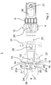
- eine Längsschnittdarstellung einer ersten Ausgestaltung eines hydraulischen Arbeitsgerätes gemäß der Erfindung;
- Fig. 2
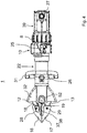
- eine Darstellung in Draufsicht auf die Ausgestaltung des hydraulischen Arbeitsgerätes gemäß
Fig. 1 ; - Fig. 3
- eine perspektivische Darstellung der Ausgestaltung des hydraulischen Arbeitsgerätes gemäß
Fig. 1 mit geöffneten Werkzeughälften; - Fig. 4
- eine Darstellung in Draufsicht auf eine zweite Ausgestaltung des hydraulischen Arbeitsgerätes, die nicht Gegenstand der Erfindung ist;
- Fig. 5
- eine perspektivische Darstellung der Ausgestaltung des hydraulischen Arbeitsgerätes gemäß
Fig. 4 mit geöffneten Werkzeughälften; - Fig. 6
- eine perspektivische Darstellung des Pumpengehäuses einschließlich des Steuerventils des hydraulischen Arbeitsgerätes gemäß der Erfindung;
- Fig. 7
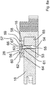
- eine Schnittansicht durch den Hydrauliktank des hydraulischen Arbeitsgerätes gemäß der Erfindung;
- Fig. 8a
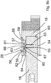
- eine Schnittdarstellung im Bereich der Verbindung zwischen erster Werkzeughälfte und zweiter Werkzeughälfte in verriegeltem Zustand;
- Fig. 8b
- eine Schnittdarstellung im Bereich der Verbindung zwischen erster Werkzeughälfte und zweiter Werkzeughälfte in entriegeltem Zustand sowie,
- Fig. 8c
- eine Schnittdarstellung im Bereich der Verbindung zwischen erster Werkzeughälfte und zweiter Werkzeughälfte bei teilweise abgezogener zweiter Werkzeughälfte.
- Fig. 1
- a longitudinal sectional view of a first embodiment of a hydraulic implement according to the invention;
- Fig. 2
- a representation in plan view of the design of the hydraulic implement according to
Fig. 1 ; - Fig. 3
- a perspective view of the design of the hydraulic implement according to
Fig. 1 with the mold halves open; - Fig. 4
- a representation in plan view of a second embodiment of the hydraulic working device, which is not the subject of the invention;
- Fig. 5
- a perspective view of the design of the hydraulic implement according to
Fig. 4 with the mold halves open; - Fig. 6
- a perspective view of the pump housing including the control valve of the hydraulic working device according to the invention;
- Fig. 7
- a sectional view through the hydraulic tank of the hydraulic working device according to the invention;
- Fig. 8a
- a sectional view in the region of the connection between the first tool half and the second tool half in the locked state;
- Fig. 8b
- 2 shows a sectional illustration in the area of the connection between the first tool half and the second tool half in the unlocked state, and
- Fig. 8c
- a sectional view in the area of the connection between the first tool half and the second tool half with the second tool half partially removed.
Bezugsziffer 1 in
Bezugszeichen 8 bezeichnet ein Steuerventil in Form eines sogenannten "Sternventils", welches dazu dient, die Fließrichtung des hydraulischen Fluids und damit die Arbeitsbewegung des Werkzeugs (Öffnen bzw. Schließen) zu steuern.
In dem Zylindergehäuse 22 befinden sich ein erster Zylinderraum 46a sowie der zweite Zylinderraum 46b, die durch den Kolben einer Kolbenstange 11 voneinander getrennt sind. Der Kolben befindet sich in
Das dem Pumpengehäuse 10 abgewandte Ende der Kolbenstange 11 steht über einen Umlenkmechanismus mit zwei Schwenkarmen 12, 13 in Verbindung, die je nach Bewegungsrichtung der Kolbenstange 11 sich aufspreizen oder aufeinander zu schwenken. Die Bezugsziffer 52 bezeichnet einen Haltebolzen, der gleichzeitig die Verschwenkachse der beiden Schwenkarme 12, 13 bildet.The end of the
Die beiden Schwenkarme 12, 13 sind an ihrem dem Bolzen 52 abgewandten Ende als erste Werkzeughälften 18, 19 ausgebildet, auf die zweite Werkzeughälften 16, 17 aufgesteckt sind.The two
Die zweiten Werkzeughälften 16, 17 bilden in dem Ausführungsbeispiel gemeinsam ein Türöffnerwerkzeug.In the exemplary embodiment, the second tool halves 16, 17 together form a door opener tool.
Bezugsziffer 25 bezeichnet eine Halterung für eine (nicht dargestellte) Beleuchtungseinrichtung. Die Beleuchtungseinrichtung ist vorzugsweise mit einer eigenen Energieversorgung ausgestattet.
Die beiden zweiten Werkzeughälften 16, 17 bilden ein Tür- oder Fensteröffnerwerkzeug. Hierzu umfassen die zweiten Werkzeughälften 16, 17 je einen senkrecht sich erstreckenden wandartigen Abschnitt 20, 21 mit sich verändernder Wandstärke. Diese beiden Abschnitte 20, 21 bilden an ihrer Vorderseite im geschlossenen Zustand der beiden zweiten Werkzeughälften 16, 17 einen senkrecht zur Verlängerung der Längsachse der Kolbenstange 11 verlaufenden, abgeflachten Stirnbereich 24. Der Stirnbereich 24 dient dazu, in einen Haustürspalt oder einen Hausfensterspalt eingesetzt zu werden. Er ermöglicht das Einbringen des Türöffnerwerkzeuges und eine optimale Krafteinleitung in den Spalt. Die beiden zweiten Werkzeughälften 16, 17 weisen auf der dem abgeflachten Stirnbereich 24 gegenüberliegenden Rückseite ebene Wandabschnitte 20a, 21a mit erhöhter Materialdicke auf, die als Anschlagfläche für einen (nicht dargestellten) Hammer oder eine (nicht dargestellte) Axt bzw. als Anlagefläche für einen (ebenso nicht dargestellten) Stab oder ein Brecheisen als Anschlagverlängerung dienen.The two second tool halves 16, 17 form a door or window opener tool. For this purpose, the second tool halves 16, 17 each comprise a vertically extending wall-
Der abgeflachte Stirnbereich 24 wird bei der Ausgestaltung nach
Gemäß
Die vordere Spitze des abgeflachten Stirnbereichs 24 besitzt eine Schräge 34, die es ermöglicht, die Spitze des Werkzeugs in einen engen Tür- bzw. Fensterspalt unter Kraftanwendung einzudrücken.The front tip of the flattened
An den vertikal zur Zeichnungsebene von
Aus
Die Werkzeughälften 16, 17 besitzen, wie aus
Die Darstellung gemäß
Das erfindungsgemäße Arbeitsgerät besitzt einen Hydrauliktank 4, welcher im Pumpengehäuse 10 untergebracht ist. Hierzu umfasst das Pumpengehäuse 10 eine durch einen Deckel 7 verschließbare Öffnung, in dem sich eine Ausgleichseinrichtung zum Beispiel in Form einer topfförmigen Gummimembran 30 befindet. Der Deckel 7 ist über Schrauben mit dem Pumpengehäuse 10 verbindbar. An der Oberseite befindet sich die Halterung 25 für die aufzusetzende Beleuchtungseinheit.The implement according to the invention has a
Das Betätigungselement 56 weist in der hier gezeigten Ausführung einen, vorzugsweise ringförmigen, Vorsprung 60 auf, der mit einer, entsprechend ringförmig ausgebildeten, Aussparung 62 zusammenwirkt, damit das Betätigungselement 56 gedrückt werden kann. Zweckmäßigerweise weist das Betätigungselement 56 einen weiteren mittigen Vorsprung 67 auf, der einer Bohrung 66 an der zweiten Werkzeughälfte 16 gegenüberliegt. Die Bohrung 66 ist zweckmäßig, um für das Verriegelungselement 53 zur Arretierung der zweiten und ersten Werkzeughälften 16, 18 Raum zu schaffen. Der Vorsprung 67 dient dazu, bei Betätigung des Betätigungselements 56 das Verriegelungselement 53 aus der Bohrung 66 gegen die Kraft der Feder 55 in die Bohrung 54 zu versenken. Hierdurch kann die Kupplung 28 entriegelt werden. Neben der Bohrung 66 befindet sich ein ringförmiger Vorsprung 61. Dem Vorsprung 61 liegt eine entsprechende Aussparung 63 in dem Betätigungselement 56 gegenüber. In diese Aussparung 63 wird der Vorsprung 61 beim Betätigen des Betätigungselements 56 versenkt. Dadurch wird eine Führung des Betätigungselements 56 erreicht.In the embodiment shown here, the
In
In
Das erfindungsgemäße Arbeitsgerät zeichnet sich durch ein geringes Gewicht sowie geringe Abmessungen aus. Des Weiteren bietet es eine sehr hohe Variabilität im Einsatz und eignet sich daher ganz besonders als begleitendes Werkzeug für Feuerwehrleute mit der Möglichkeit eines rasch durchzuführenden Zutritts in ein Gebäude. Ebenso ist das erfindungsgemäße Arbeitsgerät für den SEK-Einsatz ganz besonders geeignet.The implement according to the invention is characterized by a low weight and small dimensions. Furthermore, it offers a very high variability in use and is therefore particularly suitable as an accompanying tool for firefighters with the possibility of quick access to a building. Likewise, the working device according to the invention is very particularly suitable for the use of SEK.
- 11
- Arbeitsgerätimplement
- 22
- Hydraulikpumpehydraulic pump
- 33
- Hydraulikzylinderhydraulic cylinders
- 44
- Hydrauliktankhydraulic tank
- 55
- Hohlstabhollow bar
- 66
- Hydraulikleitunghydraulic line
- 77
- Deckelcover
- 88th
- Steuerventilcontrol valve
- 99
- Akkubattery pack
- 1010
- Pumpengehäusepump housing
- 1111
- Kolbenstangepiston rod
- 1212
- Schwenkarmswivel arm
- 1313
- Schwenkarmswivel arm
- 1616
- Zweite WerkzeughälfteSecond half of the tool
- 1717
- Zweite WerkzeughälfteSecond half of the tool
- 1818
- Erste WerkzeughälfteFirst half of the tool
- 1919
- Erste WerkzeughälfteFirst half of the tool
- 2020
- Abschnittsection
- 20a20a
- Wandabschnittwall section
- 20b20b
- Wandabschnittwall section
- 2121
- Abschnittsection
- 21a21a
- Wandabschnittwall section
- 21b21b
- Wandabschnittwall section
- 2222
- Zylindergehäusecylinder housing
- 2323
- Elektromotorelectric motor
- 2424
- Abgeflachter StirnbereichFlattened forehead area
- 2525
- Halterung für BeleuchtungseinheitBracket for lighting unit
- 2626
- Tragegurt-HalterungStrap bracket
- 2727
- Hauptschaltermain switch
- 2828
- Kupplungclutch
- 2929
- Kupplungclutch
- 3030
- Gummimembranrubber membrane
- 3131
- Handgriffhandle
- 3232
- Schutzabdeckungprotective cover
- 3333
- Tragegurt-HalterungStrap bracket
- 3434
- Schrägeslope
- 3535
- Kontaktflächecontact area
- 3636
- Kontaktflächecontact area
- 3737
- Schneidkonturcutting contour
- 3838
- Schneidkonturcutting contour
- 3939
- Motorengehäusemotor housing
- 40a40a
- Konturcontour
- 40b40b
- Konturcontour
- 4141
- Wandbereichwall area
- 4242
- DurchlassöffnungPort
- 4343
- Ausgleichsvolumencompensating volume
- 4444
- Schneidkonturcutting contour
- 4545
- Schneidkonturcutting contour
- 46a46a
- Erster ZylinderraumFirst cylinder room
- 46b46b
- Zweiter ZylinderraumSecond cylinder room
- 4747
- Bohrungdrilling
- 4848
- Deckelöffnunglid opening
- 4949
- Außenflächeouter surface
- 5050
- Außenflächeouter surface
- 5151
- ringartiger Vorsprungring-like projection
- 5252
- Bolzenbolt
- 5353
- Verriegelungselementlocking element
- 5454
- Bohrungdrilling
- 5555
- Federfeather
- 5656
- Betätigungselementactuator
- 5757
- Aussparungrecess
- 5858
- Ringring
- 5959
- Aussparungrecess
- 6060
- Vorsprunghead Start
- 6161
- Vorsprunghead Start
- 6262
- Aussparungrecess
- 6363
- Aussparungrecess
- 6464
- abgeschrägte Kantebeveled edge
- 6565
- Aussparungrecess
- 6666
- Bohrungdrilling
- 6767
- Vorsprunghead Start
Claims (13)
- Hydraulic work apparatus (1) for portable use, having
a hydraulic pump (2), a pump housing (10),
a hydraulic cylinder (3) with a piston rod (11),
a hydraulic tank (4), hydraulic lines, a compensator and a manually operable, hydraulic control valve (8),
a rechargeable battery (9) accommodated on the work apparatus (1),
two, first and second tool halves (18, 19 and 16, 17, respectively) connected to the piston rod (11) via pivot arms (12, 13), wherein the second tool halves ensure a spreading function,
each tool half (16, 17) has a wall portion (20, 21) extending perpendicularly to the extension of the longitudinal axis of the piston rod (11), and both wall portions (20, 21) jointly form, in the closed state of the two tool halves, a flattened end region (24) extending perpendicularly to the extension of the longitudinal axis of the piston rod (11), and
the second tool halves (16,17) engage in one another in the region of the flattened end region (24), characterized in that,
in order to spread doors and window gaps, the second tool halves (16, 17) have a plurality of wall portions (20b, 21b) which, located one above another, form the flattened end region (24),
the second tool halves (16, 17) are pluggable onto the first tool halves (18,19), and
the first tool half (18,19) has a cutting contour (37, 38). - Work apparatus according to Claim 1, characterized in that the flattened end region (24) is offset laterally with respect to the extension of the longitudinal axis of the piston rod (11).
- Work apparatus according to Claim 1 or 2, characterized in that the flattened end region (24) is oriented in a manner extending in an inclined manner with respect to the extension of the longitudinal axis of the piston rod (11).
- Work apparatus according to at least one of the preceding claims, characterized in that the tip of the flattened end region (24) has a bevel (34).
- Work apparatus according to at least one of the preceding claims, characterized in that the portion (20, 21) has at least one flattened wall portion (20a, 21a) at its opposite end from the end region (24).
- Work apparatus according to Claim 5, characterized in that at least one flattened wall portion (e.g. 20a) has at least one contour (40a, 40b) in the form of a knurl.
- Work apparatus according to Claim 1, characterized in that a manual coupling (28, 29) that is actuable without tools is provided between the second tool halves (16, 17) and the first tool halves (18, 19).
- Work apparatus according to Claim 1 or 7, characterized in that a preferably spring-loaded locking element (53) is accommodated in a bore (54) in each of the second tool halves (16, 17), and the first tool halves (18, 19) each comprise a, preferably plate-like, actuating element (56) for the locking element (53).
- Work apparatus according to Claim 8, characterized in that the actuating element (56) has a protrusion (67), which is located opposite a bore (66) in the first tool halves (18, 19), and the bore (66) serves to receive the locking element (53) in the locking state.
- Work apparatus according to one of Claims 1, 7-9, characterized in that the first tool half (18, 19) has a bevelled edge (64), which serves as a run-on slope for the locking element (53).
- Work apparatus according to at least one of the preceding claims, characterized in that the first tool half (18, 19) has a toothed cutting contour (37, 38).
- Work apparatus (1) according to one of the preceding claims, characterized in that the compensator and the hydraulic tank (4) are located in the pump housing (10).
- Work apparatus (1) according to one of the preceding claims, characterized in that a holder for an illumination unit (25) is located on the pump housing (10).
Priority Applications (2)
| Application Number | Priority Date | Filing Date | Title |
|---|---|---|---|
| EP18191723.8A EP3434331B1 (en) | 2015-01-26 | 2015-01-26 | Hydraulic implement |
| PL18191723T PL3434331T3 (en) | 2015-01-26 | 2015-01-26 | Hydraulic implement |
Applications Claiming Priority (3)
| Application Number | Priority Date | Filing Date | Title |
|---|---|---|---|
| EP15701218.8A EP3197564B1 (en) | 2015-01-26 | 2015-01-26 | Hydraulic implement |
| EP18191723.8A EP3434331B1 (en) | 2015-01-26 | 2015-01-26 | Hydraulic implement |
| PCT/EP2015/051510 WO2016119819A1 (en) | 2015-01-26 | 2015-01-26 | Hydraulic implement |
Related Parent Applications (2)
| Application Number | Title | Priority Date | Filing Date |
|---|---|---|---|
| EP15701218.8A Division-Into EP3197564B1 (en) | 2015-01-26 | 2015-01-26 | Hydraulic implement |
| EP15701218.8A Division EP3197564B1 (en) | 2015-01-26 | 2015-01-26 | Hydraulic implement |
Publications (3)
| Publication Number | Publication Date |
|---|---|
| EP3434331A2 EP3434331A2 (en) | 2019-01-30 |
| EP3434331A3 EP3434331A3 (en) | 2019-03-20 |
| EP3434331B1 true EP3434331B1 (en) | 2020-02-19 |
Family
ID=52396702
Family Applications (2)
| Application Number | Title | Priority Date | Filing Date |
|---|---|---|---|
| EP18191723.8A Active EP3434331B1 (en) | 2015-01-26 | 2015-01-26 | Hydraulic implement |
| EP15701218.8A Active EP3197564B1 (en) | 2015-01-26 | 2015-01-26 | Hydraulic implement |
Family Applications After (1)
| Application Number | Title | Priority Date | Filing Date |
|---|---|---|---|
| EP15701218.8A Active EP3197564B1 (en) | 2015-01-26 | 2015-01-26 | Hydraulic implement |
Country Status (6)
| Country | Link |
|---|---|
| US (2) | US10293192B2 (en) |
| EP (2) | EP3434331B1 (en) |
| CN (2) | CN108025198B (en) |
| AT (1) | AT16134U3 (en) |
| PL (2) | PL3434331T3 (en) |
| WO (1) | WO2016119819A1 (en) |
Families Citing this family (14)
| Publication number | Priority date | Publication date | Assignee | Title |
|---|---|---|---|---|
| CN108025198B (en) * | 2015-01-26 | 2019-04-19 | 鲁卡斯液压有限公司 | Hydraulic instrument |
| US10807250B2 (en) * | 2016-04-07 | 2020-10-20 | Biomet Manufacturing, Llc | Method and apparatus for processing orthopedic components |
| WO2018077418A1 (en) * | 2016-10-28 | 2018-05-03 | Lukas Hydraulik Gmbh | Shear blade and cutting device |
| EP3532229A1 (en) * | 2016-10-28 | 2019-09-04 | Lukas Hydraulik GmbH | Shear blade for a cutting device |
| AT520046B1 (en) | 2017-06-12 | 2022-10-15 | Weber Hydraulik Gmbh | Hydraulic unit for hydraulic rescue tools and rescue tools equipped therewith |
| USD900576S1 (en) * | 2018-01-02 | 2020-11-03 | Innovative Rescue Systems Llc | Hydraulic spreader |
| EP4245467A1 (en) * | 2018-06-26 | 2023-09-20 | Lukas Hydraulik GmbH | Portable working device for portable use |
| NL2021528B1 (en) * | 2018-08-30 | 2020-04-30 | Holmatro B V | A tool having a pump and a pump |
| NL2021527B1 (en) | 2018-08-30 | 2020-04-24 | Holmatro B V | Tool having a pump and a motor on a common axis |
| WO2020188702A1 (en) * | 2019-03-18 | 2020-09-24 | 株式会社オグラ | Auxiliary tool and actuation unit |
| WO2021047774A1 (en) * | 2019-09-11 | 2021-03-18 | Lukas Hydraulik Gmbh | Portable tool for mobile use |
| DE112020004755T5 (en) * | 2019-10-02 | 2022-06-15 | Husqvarna Ab | Battery adapter assembly and hand held power tool |
| US11638842B2 (en) * | 2020-10-26 | 2023-05-02 | Snap-On Incorporated | Portable electric rescue tool |
| DE102022201368A1 (en) | 2022-02-10 | 2023-08-10 | Robert Bosch Gesellschaft mit beschränkter Haftung | Pump device with clutch for drive device |
Citations (14)
| Publication number | Priority date | Publication date | Assignee | Title |
|---|---|---|---|---|
| US4333330A (en) | 1980-04-21 | 1982-06-08 | H. K. Porter, Inc. | Spreader tool |
| US4443001A (en) | 1982-05-19 | 1984-04-17 | Haerer James P | Hydraulically operated hand tool for forcing open doors |
| USRE33002E (en) | 1983-01-28 | 1989-08-01 | F. M. Brick Industries, Inc. | High-power rescue tool |
| EP0519845A1 (en) | 1991-06-20 | 1992-12-23 | Hydr'am | Independant multi-purpose tool as schear/spreader with hydraulic control |
| WO1996034657A1 (en) | 1995-05-04 | 1996-11-07 | Weber-Hydraulik Gmbh | Deforming tool |
| US5956992A (en) | 1997-01-24 | 1999-09-28 | Patton; Tommy L. | Spreading, crushing or cutting device |
| WO2000009286A1 (en) | 1998-08-13 | 2000-02-24 | Nike Hydraulics Ab | A fluid actuated rescue tool |
| US6311537B1 (en) | 1998-10-30 | 2001-11-06 | Orlando C. Vigil | Blade tip for a rescue tool |
| JP2004082273A (en) | 2002-08-27 | 2004-03-18 | Izumi Products Co | Ceiling frame separation tool |
| DE202005008658U1 (en) | 2005-06-03 | 2005-11-17 | Szautner, Roland | Illuminator for rescue cutters especially hydraulic shears has a self contained battery powered light fitted directly onto the cutters |
| DE10110882B4 (en) | 2001-03-07 | 2011-04-14 | Gustav Klauke Gmbh | Locking bolt for attaching a tool in a pressing device |
| US20110214471A1 (en) | 2010-02-15 | 2011-09-08 | Altair Engineering, Inc. | Portable rescue tool and method of use |
| EP2700863A1 (en) | 2011-04-18 | 2014-02-26 | Kabushiki Kaisha Ogura | Hydraulic joint structure, hydraulic operation device with hydraulic joint structure, joint portion constituting hydraulic joint structure, hydraulic pressure generation unit with joint portion, front end tool unit with joint portion, and hydraulic hose unit with joint portion |
| WO2015003198A1 (en) | 2013-07-11 | 2015-01-15 | Weber-Hydraulik Gmbh | Spreader tip for a rescue tool |
Family Cites Families (14)
| Publication number | Priority date | Publication date | Assignee | Title |
|---|---|---|---|---|
| US444301A (en) | 1891-01-06 | Self-closing can | ||
| US4392263A (en) * | 1981-02-02 | 1983-07-12 | Amoroso Michael J | Portable rescue tool |
| US4762304A (en) * | 1986-04-26 | 1988-08-09 | Stafford Hill Arms Company Limited | Fluid-operated door opener |
| DE59002832D1 (en) | 1989-09-28 | 1993-10-28 | Kugelfischer G Schaefer & Co | Hydraulic unit. |
| US5297780A (en) * | 1992-09-29 | 1994-03-29 | Curtiss Wright Flight Systems Inc. | Rescue spreading tool |
| DE9215062U1 (en) | 1992-11-05 | 1992-12-24 | Fag Kugelfischer Georg Schaefer Kgaa, 8720 Schweinfurt, De | |
| US5505431A (en) * | 1993-10-28 | 1996-04-09 | Iowa-American Firefighting Equipment Co. | Forcible entry tool |
| US5398773A (en) * | 1994-04-22 | 1995-03-21 | Baker; Charles W. | Forcing tool for locked doors, gates and the like |
| DE10028957C2 (en) * | 2000-06-16 | 2002-07-11 | Lukas Hydraulik Gmbh & Co Kg | Portable hydraulic pump unit |
| EP1658907A1 (en) * | 2004-11-17 | 2006-05-24 | Dino Sodini | Device for correcting damaged vehicle body sheets |
| GB2435003B (en) * | 2006-02-10 | 2008-06-11 | Textron Fastening Syst Ltd | Apparatus for swaging a collar onto an externally grooved member |
| US7568372B1 (en) * | 2008-05-13 | 2009-08-04 | Tommy L. Patton | Hydraulic rescue tool |
| US8727317B2 (en) * | 2011-05-23 | 2014-05-20 | Lukas Hydraulik Gmbh | Rescue cylinder |
| CN108025198B (en) * | 2015-01-26 | 2019-04-19 | 鲁卡斯液压有限公司 | Hydraulic instrument |
-
2015
- 2015-01-26 CN CN201580063702.7A patent/CN108025198B/en active Active
- 2015-01-26 PL PL18191723T patent/PL3434331T3/en unknown
- 2015-01-26 PL PL15701218T patent/PL3197564T3/en unknown
- 2015-01-26 EP EP18191723.8A patent/EP3434331B1/en active Active
- 2015-01-26 CN CN201910310489.5A patent/CN110038236B/en active Active
- 2015-01-26 WO PCT/EP2015/051510 patent/WO2016119819A1/en active Application Filing
- 2015-01-26 US US15/546,228 patent/US10293192B2/en active Active
- 2015-01-26 EP EP15701218.8A patent/EP3197564B1/en active Active
- 2015-01-26 AT ATGM50147/2018U patent/AT16134U3/en unknown
-
2019
- 2019-02-26 US US16/286,201 patent/US10589135B2/en active Active
Patent Citations (15)
| Publication number | Priority date | Publication date | Assignee | Title |
|---|---|---|---|---|
| US4333330A (en) | 1980-04-21 | 1982-06-08 | H. K. Porter, Inc. | Spreader tool |
| US4443001A (en) | 1982-05-19 | 1984-04-17 | Haerer James P | Hydraulically operated hand tool for forcing open doors |
| USRE33002E (en) | 1983-01-28 | 1989-08-01 | F. M. Brick Industries, Inc. | High-power rescue tool |
| EP0519845A1 (en) | 1991-06-20 | 1992-12-23 | Hydr'am | Independant multi-purpose tool as schear/spreader with hydraulic control |
| DE69221221T2 (en) | 1991-06-20 | 1997-11-27 | Hydr Am | Autonomous multi-purpose tool such as scissors / spreader with hydraulic drive |
| WO1996034657A1 (en) | 1995-05-04 | 1996-11-07 | Weber-Hydraulik Gmbh | Deforming tool |
| US5956992A (en) | 1997-01-24 | 1999-09-28 | Patton; Tommy L. | Spreading, crushing or cutting device |
| WO2000009286A1 (en) | 1998-08-13 | 2000-02-24 | Nike Hydraulics Ab | A fluid actuated rescue tool |
| US6311537B1 (en) | 1998-10-30 | 2001-11-06 | Orlando C. Vigil | Blade tip for a rescue tool |
| DE10110882B4 (en) | 2001-03-07 | 2011-04-14 | Gustav Klauke Gmbh | Locking bolt for attaching a tool in a pressing device |
| JP2004082273A (en) | 2002-08-27 | 2004-03-18 | Izumi Products Co | Ceiling frame separation tool |
| DE202005008658U1 (en) | 2005-06-03 | 2005-11-17 | Szautner, Roland | Illuminator for rescue cutters especially hydraulic shears has a self contained battery powered light fitted directly onto the cutters |
| US20110214471A1 (en) | 2010-02-15 | 2011-09-08 | Altair Engineering, Inc. | Portable rescue tool and method of use |
| EP2700863A1 (en) | 2011-04-18 | 2014-02-26 | Kabushiki Kaisha Ogura | Hydraulic joint structure, hydraulic operation device with hydraulic joint structure, joint portion constituting hydraulic joint structure, hydraulic pressure generation unit with joint portion, front end tool unit with joint portion, and hydraulic hose unit with joint portion |
| WO2015003198A1 (en) | 2013-07-11 | 2015-01-15 | Weber-Hydraulik Gmbh | Spreader tip for a rescue tool |
Non-Patent Citations (5)
| Title |
|---|
| ANONYMOUS, CATALOG OF HYDRAULIC RESCUE EQUIPMENT, 20 August 2013 (2013-08-20), pages 1 - 20, XP055520571, Retrieved from the Internet <URL:https://web.archive.org/web/20130820100232> [retrieved on 20181031] |
| ANONYMOUS: "Battery Tools - E-FORCE", WEBER RESCUE BROCHURE, 1 July 2012 (2012-07-01), pages 1 - 8, XP055654916 |
| ANONYMUS: "Hurst Jaws of Life - Blockbuster and Lip Tips", HALE PRODUCTS INC., 1 January 2002 (2002-01-01), pages 1, XP055714061 |
| ANONYMUS: "Rettungssysteme. Hurst Jaws of Life", HURST EMERGENCY PRODUCTS, pages 1 - 32, XP055714056, [retrieved on 20200713] |
| LUKAS HYDRAULIK ET AL., ERSATZTEILLISTE / SPARE PARTS LIST SC357E2_SPARES_90-30- 22_DE_EN.INDD, May 2014 (2014-05-01), pages 1 - 13, XP055213518, Retrieved from the Internet <URL:http://rettunq.lukas.com/lukas rescue media/09 Dokumentation/05 Kombiqerät e/SC 357 E2/SC357E2 spares mail 90 30 22 de en-p-2978.pdf> [retrieved on 20150915] |
Also Published As
| Publication number | Publication date |
|---|---|
| AT16134U2 (en) | 2019-02-15 |
| US10589135B2 (en) | 2020-03-17 |
| WO2016119819A1 (en) | 2016-08-04 |
| EP3197564B1 (en) | 2019-01-09 |
| EP3197564A1 (en) | 2017-08-02 |
| AT16134U3 (en) | 2020-05-15 |
| PL3197564T3 (en) | 2019-07-31 |
| CN108025198B (en) | 2019-04-19 |
| CN110038236B (en) | 2020-12-29 |
| US10293192B2 (en) | 2019-05-21 |
| EP3434331A3 (en) | 2019-03-20 |
| EP3434331A2 (en) | 2019-01-30 |
| US20190224504A1 (en) | 2019-07-25 |
| PL3434331T3 (en) | 2020-08-10 |
| CN108025198A (en) | 2018-05-11 |
| US20180021603A1 (en) | 2018-01-25 |
| CN110038236A (en) | 2019-07-23 |
Similar Documents
| Publication | Publication Date | Title |
|---|---|---|
| EP3434331B1 (en) | Hydraulic implement | |
| DE4000489C2 (en) | ||
| DE19926481B4 (en) | Hydraulic implement | |
| DE19737133C2 (en) | Fluid operated device for use with a variety of tools | |
| DE102005016356A1 (en) | tongs | |
| DE4041401A1 (en) | RESCUE TOOL | |
| AT515267B1 (en) | Attachment for a pressing device | |
| DE112015001669T5 (en) | jig | |
| EP2883658B1 (en) | Attachment for a pressing device | |
| DE3690236C2 (en) | Blind riveter accessory for drilling machine | |
| DE202016007588U1 (en) | Screw-in aid for holding and aligning a screw | |
| DE102014010021B4 (en) | Tree felling wedge | |
| EP2576152B1 (en) | Device holder | |
| DE102016100687B4 (en) | Nut riveting gun | |
| AT14508U1 (en) | DEVICE FOR DRIVING A MOVABLE FURNITURE PART | |
| LU101822B1 (en) | Hole saw assembly for a drilling machine and horizontal hole saw for a hole saw assembly | |
| EP1956691A2 (en) | Cable processing device with several processing stations for assembling a cable | |
| AT16783U1 (en) | HYDRAULIC WORK EQUIPMENT | |
| DE202015009395U1 (en) | Hydraulic implement | |
| AT15874U1 (en) | HYDRAULIC WORKING DEVICE | |
| DE202015009741U1 (en) | Hydraulic implement | |
| DE202015009638U1 (en) | Hydraulic implement | |
| DE4239786A1 (en) | Wooden log splitter with splitting blade - has log holder in form of mandrel whose tip points in splitting direction | |
| EP1393870B1 (en) | Wood splitting machine | |
| DE102014117600A1 (en) | Swivel jaws and motor-operated hand-held device |
Legal Events
| Date | Code | Title | Description |
|---|---|---|---|
| PUAI | Public reference made under article 153(3) epc to a published international application that has entered the european phase |
Free format text: ORIGINAL CODE: 0009012 |
|
| STAA | Information on the status of an ep patent application or granted ep patent |
Free format text: STATUS: THE APPLICATION HAS BEEN PUBLISHED |
|
| AC | Divisional application: reference to earlier application |
Ref document number: 3197564 Country of ref document: EP Kind code of ref document: P |
|
| AK | Designated contracting states |
Kind code of ref document: A2 Designated state(s): AL AT BE BG CH CY CZ DE DK EE ES FI FR GB GR HR HU IE IS IT LI LT LU LV MC MK MT NL NO PL PT RO RS SE SI SK SM TR |
|
| PUAL | Search report despatched |
Free format text: ORIGINAL CODE: 0009013 |
|
| AK | Designated contracting states |
Kind code of ref document: A3 Designated state(s): AL AT BE BG CH CY CZ DE DK EE ES FI FR GB GR HR HU IE IS IT LI LT LU LV MC MK MT NL NO PL PT RO RS SE SI SK SM TR |
|
| RIC1 | Information provided on ipc code assigned before grant |
Ipc: A62B 3/00 20060101AFI20190211BHEP Ipc: B25B 28/00 20060101ALN20190211BHEP |
|
| STAA | Information on the status of an ep patent application or granted ep patent |
Free format text: STATUS: REQUEST FOR EXAMINATION WAS MADE |
|
| 17P | Request for examination filed |
Effective date: 20190903 |
|
| RBV | Designated contracting states (corrected) |
Designated state(s): AL AT BE BG CH CY CZ DE DK EE ES FI FR GB GR HR HU IE IS IT LI LT LU LV MC MK MT NL NO PL PT RO RS SE SI SK SM TR |
|
| GRAP | Despatch of communication of intention to grant a patent |
Free format text: ORIGINAL CODE: EPIDOSNIGR1 |
|
| STAA | Information on the status of an ep patent application or granted ep patent |
Free format text: STATUS: GRANT OF PATENT IS INTENDED |
|
| RIC1 | Information provided on ipc code assigned before grant |
Ipc: B25B 28/00 20060101ALN20191021BHEP Ipc: A62B 3/00 20060101AFI20191021BHEP |
|
| TPAC | Observations filed by third parties |
Free format text: ORIGINAL CODE: EPIDOSNTIPA |
|
| GRAS | Grant fee paid |
Free format text: ORIGINAL CODE: EPIDOSNIGR3 |
|
| INTG | Intention to grant announced |
Effective date: 20191127 |
|
| GRAA | (expected) grant |
Free format text: ORIGINAL CODE: 0009210 |
|
| STAA | Information on the status of an ep patent application or granted ep patent |
Free format text: STATUS: THE PATENT HAS BEEN GRANTED |
|
| AC | Divisional application: reference to earlier application |
Ref document number: 3197564 Country of ref document: EP Kind code of ref document: P |
|
| AK | Designated contracting states |
Kind code of ref document: B1 Designated state(s): AL AT BE BG CH CY CZ DE DK EE ES FI FR GB GR HR HU IE IS IT LI LT LU LV MC MK MT NL NO PL PT RO RS SE SI SK SM TR |
|
| REG | Reference to a national code |
Ref country code: CH Ref legal event code: EP |
|
| REG | Reference to a national code |
Ref country code: DE Ref legal event code: R096 Ref document number: 502015011816 Country of ref document: DE |
|
| REG | Reference to a national code |
Ref country code: AT Ref legal event code: REF Ref document number: 1234257 Country of ref document: AT Kind code of ref document: T Effective date: 20200315 |
|
| REG | Reference to a national code |
Ref country code: IE Ref legal event code: FG4D Free format text: LANGUAGE OF EP DOCUMENT: GERMAN |
|
| REG | Reference to a national code |
Ref country code: DE Ref legal event code: R026 Ref document number: 502015011816 Country of ref document: DE |
|
| PLBI | Opposition filed |
Free format text: ORIGINAL CODE: 0009260 |
|
| REG | Reference to a national code |
Ref country code: NL Ref legal event code: FP |
|
| REG | Reference to a national code |
Ref country code: FI Ref legal event code: MDE Opponent name: WEBER-HYDRAULIK GMBH |
|
| 26 | Opposition filed |
Opponent name: WEBER-HYDRAULIK GMBH Effective date: 20200330 |
|
| PG25 | Lapsed in a contracting state [announced via postgrant information from national office to epo] |
Ref country code: FI Free format text: LAPSE BECAUSE OF FAILURE TO SUBMIT A TRANSLATION OF THE DESCRIPTION OR TO PAY THE FEE WITHIN THE PRESCRIBED TIME-LIMIT Effective date: 20200219 Ref country code: RS Free format text: LAPSE BECAUSE OF FAILURE TO SUBMIT A TRANSLATION OF THE DESCRIPTION OR TO PAY THE FEE WITHIN THE PRESCRIBED TIME-LIMIT Effective date: 20200219 Ref country code: NO Free format text: LAPSE BECAUSE OF FAILURE TO SUBMIT A TRANSLATION OF THE DESCRIPTION OR TO PAY THE FEE WITHIN THE PRESCRIBED TIME-LIMIT Effective date: 20200519 |
|
| REG | Reference to a national code |
Ref country code: LT Ref legal event code: MG4D |
|
| PG25 | Lapsed in a contracting state [announced via postgrant information from national office to epo] |
Ref country code: IS Free format text: LAPSE BECAUSE OF FAILURE TO SUBMIT A TRANSLATION OF THE DESCRIPTION OR TO PAY THE FEE WITHIN THE PRESCRIBED TIME-LIMIT Effective date: 20200619 Ref country code: LV Free format text: LAPSE BECAUSE OF FAILURE TO SUBMIT A TRANSLATION OF THE DESCRIPTION OR TO PAY THE FEE WITHIN THE PRESCRIBED TIME-LIMIT Effective date: 20200219 Ref country code: SE Free format text: LAPSE BECAUSE OF FAILURE TO SUBMIT A TRANSLATION OF THE DESCRIPTION OR TO PAY THE FEE WITHIN THE PRESCRIBED TIME-LIMIT Effective date: 20200219 Ref country code: HR Free format text: LAPSE BECAUSE OF FAILURE TO SUBMIT A TRANSLATION OF THE DESCRIPTION OR TO PAY THE FEE WITHIN THE PRESCRIBED TIME-LIMIT Effective date: 20200219 Ref country code: BG Free format text: LAPSE BECAUSE OF FAILURE TO SUBMIT A TRANSLATION OF THE DESCRIPTION OR TO PAY THE FEE WITHIN THE PRESCRIBED TIME-LIMIT Effective date: 20200519 Ref country code: GR Free format text: LAPSE BECAUSE OF FAILURE TO SUBMIT A TRANSLATION OF THE DESCRIPTION OR TO PAY THE FEE WITHIN THE PRESCRIBED TIME-LIMIT Effective date: 20200520 |
|
| PG25 | Lapsed in a contracting state [announced via postgrant information from national office to epo] |
Ref country code: SK Free format text: LAPSE BECAUSE OF FAILURE TO SUBMIT A TRANSLATION OF THE DESCRIPTION OR TO PAY THE FEE WITHIN THE PRESCRIBED TIME-LIMIT Effective date: 20200219 Ref country code: ES Free format text: LAPSE BECAUSE OF FAILURE TO SUBMIT A TRANSLATION OF THE DESCRIPTION OR TO PAY THE FEE WITHIN THE PRESCRIBED TIME-LIMIT Effective date: 20200219 Ref country code: RO Free format text: LAPSE BECAUSE OF FAILURE TO SUBMIT A TRANSLATION OF THE DESCRIPTION OR TO PAY THE FEE WITHIN THE PRESCRIBED TIME-LIMIT Effective date: 20200219 Ref country code: CZ Free format text: LAPSE BECAUSE OF FAILURE TO SUBMIT A TRANSLATION OF THE DESCRIPTION OR TO PAY THE FEE WITHIN THE PRESCRIBED TIME-LIMIT Effective date: 20200219 Ref country code: LT Free format text: LAPSE BECAUSE OF FAILURE TO SUBMIT A TRANSLATION OF THE DESCRIPTION OR TO PAY THE FEE WITHIN THE PRESCRIBED TIME-LIMIT Effective date: 20200219 Ref country code: PT Free format text: LAPSE BECAUSE OF FAILURE TO SUBMIT A TRANSLATION OF THE DESCRIPTION OR TO PAY THE FEE WITHIN THE PRESCRIBED TIME-LIMIT Effective date: 20200712 Ref country code: DK Free format text: LAPSE BECAUSE OF FAILURE TO SUBMIT A TRANSLATION OF THE DESCRIPTION OR TO PAY THE FEE WITHIN THE PRESCRIBED TIME-LIMIT Effective date: 20200219 Ref country code: EE Free format text: LAPSE BECAUSE OF FAILURE TO SUBMIT A TRANSLATION OF THE DESCRIPTION OR TO PAY THE FEE WITHIN THE PRESCRIBED TIME-LIMIT Effective date: 20200219 Ref country code: SM Free format text: LAPSE BECAUSE OF FAILURE TO SUBMIT A TRANSLATION OF THE DESCRIPTION OR TO PAY THE FEE WITHIN THE PRESCRIBED TIME-LIMIT Effective date: 20200219 |
|
| PLAX | Notice of opposition and request to file observation + time limit sent |
Free format text: ORIGINAL CODE: EPIDOSNOBS2 |
|
| PG25 | Lapsed in a contracting state [announced via postgrant information from national office to epo] |
Ref country code: IT Free format text: LAPSE BECAUSE OF FAILURE TO SUBMIT A TRANSLATION OF THE DESCRIPTION OR TO PAY THE FEE WITHIN THE PRESCRIBED TIME-LIMIT Effective date: 20200219 |
|
| PG25 | Lapsed in a contracting state [announced via postgrant information from national office to epo] |
Ref country code: SI Free format text: LAPSE BECAUSE OF FAILURE TO SUBMIT A TRANSLATION OF THE DESCRIPTION OR TO PAY THE FEE WITHIN THE PRESCRIBED TIME-LIMIT Effective date: 20200219 |
|
| PLBB | Reply of patent proprietor to notice(s) of opposition received |
Free format text: ORIGINAL CODE: EPIDOSNOBS3 |
|
| PG25 | Lapsed in a contracting state [announced via postgrant information from national office to epo] |
Ref country code: MC Free format text: LAPSE BECAUSE OF FAILURE TO SUBMIT A TRANSLATION OF THE DESCRIPTION OR TO PAY THE FEE WITHIN THE PRESCRIBED TIME-LIMIT Effective date: 20200219 |
|
| REG | Reference to a national code |
Ref country code: CH Ref legal event code: PL |
|
| GBPC | Gb: european patent ceased through non-payment of renewal fee |
Effective date: 20210126 |
|
| PG25 | Lapsed in a contracting state [announced via postgrant information from national office to epo] |
Ref country code: LU Free format text: LAPSE BECAUSE OF NON-PAYMENT OF DUE FEES Effective date: 20210126 |
|
| REG | Reference to a national code |
Ref country code: BE Ref legal event code: MM Effective date: 20210131 |
|
| PG25 | Lapsed in a contracting state [announced via postgrant information from national office to epo] |
Ref country code: FR Free format text: LAPSE BECAUSE OF NON-PAYMENT OF DUE FEES Effective date: 20210131 |
|
| PG25 | Lapsed in a contracting state [announced via postgrant information from national office to epo] |
Ref country code: CH Free format text: LAPSE BECAUSE OF NON-PAYMENT OF DUE FEES Effective date: 20210131 Ref country code: LI Free format text: LAPSE BECAUSE OF NON-PAYMENT OF DUE FEES Effective date: 20210131 Ref country code: GB Free format text: LAPSE BECAUSE OF NON-PAYMENT OF DUE FEES Effective date: 20210126 |
|
| PG25 | Lapsed in a contracting state [announced via postgrant information from national office to epo] |
Ref country code: IE Free format text: LAPSE BECAUSE OF NON-PAYMENT OF DUE FEES Effective date: 20210126 |
|
| RDAF | Communication despatched that patent is revoked |
Free format text: ORIGINAL CODE: EPIDOSNREV1 |
|
| APBM | Appeal reference recorded |
Free format text: ORIGINAL CODE: EPIDOSNREFNO |
|
| APBP | Date of receipt of notice of appeal recorded |
Free format text: ORIGINAL CODE: EPIDOSNNOA2O |
|
| APAH | Appeal reference modified |
Free format text: ORIGINAL CODE: EPIDOSCREFNO |
|
| PG25 | Lapsed in a contracting state [announced via postgrant information from national office to epo] |
Ref country code: BE Free format text: LAPSE BECAUSE OF NON-PAYMENT OF DUE FEES Effective date: 20210131 |
|
| APBQ | Date of receipt of statement of grounds of appeal recorded |
Free format text: ORIGINAL CODE: EPIDOSNNOA3O |
|
| PGFP | Annual fee paid to national office [announced via postgrant information from national office to epo] |
Ref country code: AT Payment date: 20230120 Year of fee payment: 9 |
|
| PGFP | Annual fee paid to national office [announced via postgrant information from national office to epo] |
Ref country code: PL Payment date: 20230116 Year of fee payment: 9 Ref country code: DE Payment date: 20230123 Year of fee payment: 9 |
|
| P01 | Opt-out of the competence of the unified patent court (upc) registered |
Effective date: 20230510 |
|
| PG25 | Lapsed in a contracting state [announced via postgrant information from national office to epo] |
Ref country code: CY Free format text: LAPSE BECAUSE OF FAILURE TO SUBMIT A TRANSLATION OF THE DESCRIPTION OR TO PAY THE FEE WITHIN THE PRESCRIBED TIME-LIMIT Effective date: 20200219 |
|
| PGFP | Annual fee paid to national office [announced via postgrant information from national office to epo] |
Ref country code: NL Payment date: 20230119 Year of fee payment: 9 |
|
| PG25 | Lapsed in a contracting state [announced via postgrant information from national office to epo] |
Ref country code: HU Free format text: LAPSE BECAUSE OF FAILURE TO SUBMIT A TRANSLATION OF THE DESCRIPTION OR TO PAY THE FEE WITHIN THE PRESCRIBED TIME-LIMIT; INVALID AB INITIO Effective date: 20150126 |
|
| APBU | Appeal procedure closed |
Free format text: ORIGINAL CODE: EPIDOSNNOA9O |
|
| PGFP | Annual fee paid to national office [announced via postgrant information from national office to epo] |
Ref country code: NL Payment date: 20240119 Year of fee payment: 10 |
|
| PGFP | Annual fee paid to national office [announced via postgrant information from national office to epo] |
Ref country code: AT Payment date: 20240122 Year of fee payment: 10 |