EP3434299B1 - Medizinische fluidinjektionsvorrichtung zur einstellung des innendrucks - Google Patents
Medizinische fluidinjektionsvorrichtung zur einstellung des innendrucks Download PDFInfo
- Publication number
- EP3434299B1 EP3434299B1 EP17782642.7A EP17782642A EP3434299B1 EP 3434299 B1 EP3434299 B1 EP 3434299B1 EP 17782642 A EP17782642 A EP 17782642A EP 3434299 B1 EP3434299 B1 EP 3434299B1
- Authority
- EP
- European Patent Office
- Prior art keywords
- gas
- liquid medicine
- space
- switch
- hole
- Prior art date
- Legal status (The legal status is an assumption and is not a legal conclusion. Google has not performed a legal analysis and makes no representation as to the accuracy of the status listed.)
- Active
Links
Images


Classifications
-
- A—HUMAN NECESSITIES
- A61—MEDICAL OR VETERINARY SCIENCE; HYGIENE
- A61M—DEVICES FOR INTRODUCING MEDIA INTO, OR ONTO, THE BODY; DEVICES FOR TRANSDUCING BODY MEDIA OR FOR TAKING MEDIA FROM THE BODY; DEVICES FOR PRODUCING OR ENDING SLEEP OR STUPOR
- A61M5/00—Devices for bringing media into the body in a subcutaneous, intra-vascular or intramuscular way; Accessories therefor, e.g. filling or cleaning devices, arm-rests
- A61M5/14—Infusion devices, e.g. infusing by gravity; Blood infusion; Accessories therefor
- A61M5/142—Pressure infusion, e.g. using pumps
- A61M5/145—Pressure infusion, e.g. using pumps using pressurised reservoirs, e.g. pressurised by means of pistons
- A61M5/1452—Pressure infusion, e.g. using pumps using pressurised reservoirs, e.g. pressurised by means of pistons pressurised by means of pistons
- A61M5/14526—Pressure infusion, e.g. using pumps using pressurised reservoirs, e.g. pressurised by means of pistons pressurised by means of pistons the piston being actuated by fluid pressure
-
- A—HUMAN NECESSITIES
- A61—MEDICAL OR VETERINARY SCIENCE; HYGIENE
- A61M—DEVICES FOR INTRODUCING MEDIA INTO, OR ONTO, THE BODY; DEVICES FOR TRANSDUCING BODY MEDIA OR FOR TAKING MEDIA FROM THE BODY; DEVICES FOR PRODUCING OR ENDING SLEEP OR STUPOR
- A61M5/00—Devices for bringing media into the body in a subcutaneous, intra-vascular or intramuscular way; Accessories therefor, e.g. filling or cleaning devices, arm-rests
- A61M5/14—Infusion devices, e.g. infusing by gravity; Blood infusion; Accessories therefor
- A61M5/168—Means for controlling media flow to the body or for metering media to the body, e.g. drip meters, counters ; Monitoring media flow to the body
- A61M5/16877—Adjusting flow; Devices for setting a flow rate
- A61M5/16881—Regulating valves
-
- A—HUMAN NECESSITIES
- A61—MEDICAL OR VETERINARY SCIENCE; HYGIENE
- A61M—DEVICES FOR INTRODUCING MEDIA INTO, OR ONTO, THE BODY; DEVICES FOR TRANSDUCING BODY MEDIA OR FOR TAKING MEDIA FROM THE BODY; DEVICES FOR PRODUCING OR ENDING SLEEP OR STUPOR
- A61M5/00—Devices for bringing media into the body in a subcutaneous, intra-vascular or intramuscular way; Accessories therefor, e.g. filling or cleaning devices, arm-rests
- A61M5/178—Syringes
- A61M5/31—Details
- A61M5/315—Pistons; Piston-rods; Guiding, blocking or restricting the movement of the rod or piston; Appliances on the rod for facilitating dosing ; Dosing mechanisms
- A61M5/31511—Piston or piston-rod constructions, e.g. connection of piston with piston-rod
- A61M5/31515—Connection of piston with piston rod
-
- A—HUMAN NECESSITIES
- A61—MEDICAL OR VETERINARY SCIENCE; HYGIENE
- A61M—DEVICES FOR INTRODUCING MEDIA INTO, OR ONTO, THE BODY; DEVICES FOR TRANSDUCING BODY MEDIA OR FOR TAKING MEDIA FROM THE BODY; DEVICES FOR PRODUCING OR ENDING SLEEP OR STUPOR
- A61M5/00—Devices for bringing media into the body in a subcutaneous, intra-vascular or intramuscular way; Accessories therefor, e.g. filling or cleaning devices, arm-rests
- A61M5/14—Infusion devices, e.g. infusing by gravity; Blood infusion; Accessories therefor
- A61M5/142—Pressure infusion, e.g. using pumps
- A61M2005/14204—Pressure infusion, e.g. using pumps with gas-producing electrochemical cell
-
- A—HUMAN NECESSITIES
- A61—MEDICAL OR VETERINARY SCIENCE; HYGIENE
- A61M—DEVICES FOR INTRODUCING MEDIA INTO, OR ONTO, THE BODY; DEVICES FOR TRANSDUCING BODY MEDIA OR FOR TAKING MEDIA FROM THE BODY; DEVICES FOR PRODUCING OR ENDING SLEEP OR STUPOR
- A61M2205/00—General characteristics of the apparatus
- A61M2205/33—Controlling, regulating or measuring
- A61M2205/3331—Pressure; Flow
- A61M2205/3341—Pressure; Flow stabilising pressure or flow to avoid excessive variation
-
- A—HUMAN NECESSITIES
- A61—MEDICAL OR VETERINARY SCIENCE; HYGIENE
- A61M—DEVICES FOR INTRODUCING MEDIA INTO, OR ONTO, THE BODY; DEVICES FOR TRANSDUCING BODY MEDIA OR FOR TAKING MEDIA FROM THE BODY; DEVICES FOR PRODUCING OR ENDING SLEEP OR STUPOR
- A61M2205/00—General characteristics of the apparatus
- A61M2205/33—Controlling, regulating or measuring
- A61M2205/3368—Temperature
- A61M2205/3372—Temperature compensation
Definitions
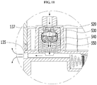
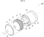
- the body part 520 of the pressure regulating valve has a generally cylindrical shape and can be coupled to an inner surface of the boss 137 in a fitting manner as shown in these figures.
- the present invention is not limited thereto.
- the body part 520 of the pressure regulating valve may be installed in the boss 137 by various methods such as ultrasonic welding.
- the body part 131 of the gas-generating unit 130 may include the external air entrance 135 connected to the switch cylinder 310.
- the external air entrance 135 is formed in a side surface of the body part 131 of the gas-generating unit 130 and is connected to the first hole 311 of the switch cylinder 310.
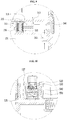
- the shut-off valve 320' when the liquid medicine storage space is filled with the liquid medicine prior to the generation of the gas in the gas-generating unit 130, the shut-off valve 320' is positioned at a location where external air from the external air entrance 135 is caused to flow into the external air inflow space 222 and the external air inflow space 222 is in communication with the gas-supplied space 116, thereby equilibrating the internal pressure of the gas-supplied space 116 to the atmospheric pressure (see FIGS. 14 and 16 ). Therefore, when the operation of filling the liquid medicine storage space 114 of the cylinder 110 with the liquid medicine is performed as preparation for injection of the liquid medicine into the patient's body (see FIG.
- a plurality of ring-shaped protrusions preferably at least two, and more preferably four ring-shaped protrusions 3240a, 3240b, 3240c and 3240d may be formed on a circumference of the body part 324 of the shut-off valve 320' (See FIGS. 14 and 15 ). At least one protrusion 3240c of the ring-shaped protrusions is in close contact with a gentle stepped portion 1362 formed on the guide wall 242 of the internal connection passage 220 (see FIG. 16 ).
- shut-off valve 320' is moved toward the external air inflow space 222 so that the front end 322' of the shut-off valve 320' is brought into contact with the sealing member 380.
- the front end 322' of the shut-off valve 320' presses against and is brought into contact with the rubber packing member 384 constituting the sealing member 380
- the front end 322' of the shut-off valve 320' is in close contact with and blocked by the rubber packing member 384, so that it is possible to reliably prevent external air from leaking to the through hole 326 formed at the front end 322' of the shut-off valve 320'.
Landscapes
- Health & Medical Sciences (AREA)
- Vascular Medicine (AREA)
- Engineering & Computer Science (AREA)
- Anesthesiology (AREA)
- Biomedical Technology (AREA)
- Heart & Thoracic Surgery (AREA)
- Hematology (AREA)
- Life Sciences & Earth Sciences (AREA)
- Animal Behavior & Ethology (AREA)
- General Health & Medical Sciences (AREA)
- Public Health (AREA)
- Veterinary Medicine (AREA)
- Physics & Mathematics (AREA)
- Fluid Mechanics (AREA)
- Infusion, Injection, And Reservoir Apparatuses (AREA)
Claims (13)
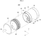
- Gerät (1000') zur Injektion flüssiger Arzneimittel mit einstellbarem Innendruck, umfassend:einen Zylinder (110), der ein Ende aufweist, an das eine Strömungsleitung (150) für flüssige Arzneimittel (150) angeschlossen ist, wobei an das andere Ende eine gaserzeugende Einheit (130) gekoppelt ist, wobei ein flüssiges Arzneimittel durch die Strömungsleitung (150) für flüssige Arzneimittel in den Zylinder (110) und aus diesem heraus strömt und die gaserzeugende Einheit (130) einen gaserzeugenden Raum (139) aufweist, in dem ein Gas erzeugt wird;einen Injektionskolben (140), der abdichtend in dem Zylinder (110) verschiebbar ist und einen Innenraum des Zylinders (110) in einen Speicherraum (114) für flüssige Arzneimittel und einen mit Gas versorgten Raum (116) unterteilt, wobei das flüssige Arzneimittel durch die Strömungsleitung (150) für flüssige Arzneimittel strömt und den Speicherraum (114) für flüssige Arzneimittel füllt, und das Gas, das in der gaserzeugenden Einheit (130) erzeugt wird, dem mit Gas versorgten Raum (116) zugeführt wird;wobei es ferner dadurch gekennzeichnet ist, dass es ein Umschaltglied (136) aufweist, das zwischen dem mit Gas versorgten Raum (116) und dem gaserzeugenden Raum (139) bereitgestellt ist, um beim Befüllen des Speicherraums (114) für flüssige Arzneimittel mit dem flüssigen Arzneimittel den mit Gas versorgten Raum (116) mit einer Atmosphäre zu verbinden und um beim Injizieren des flüssigen Arzneimittels den mit Gas versorgten Raum (116) mit dem gaserzeugenden Raum (139) zu verbinden, wobei das Umschaltglied (136) derart in der gaserzeugenden Einheit (130) angeordnet ist, dass es dem Inneren des mit Gas versorgten Raums (116) zugewandt ist;wobei das Umschaltglied (136) einen innenliegenden Verbindungsdurchgang (220), eine Einlassöffnung (135) für Außenluft, die auf einer Seite der gaserzeugenden Einheit (130) gebildet ist, mit dem mit Gas versorgten Raum (116) zu verbinden, und ein Sperrventil (320') aufweist, wobei das Sperrventil (320') abdichtend in dem innenliegenden Verbindungsdurchgang (220) verschiebbar ist und den innenliegenden Verbindungsdurchgang (220) in einen Raum (222) zum Einströmen von Außenluft, in den Außenluft aus der Einlassöffnung (135) für Außenluft einströmen kann, und einen Raum (224) zum Einströmen von erzeugtem Gas unterteilt, in den das Gas aus der der gaserzeugende Einheit (130) einströmt;wobei, wenn der Speicherraum (114) für flüssige Arzneimittel mit dem flüssigen Arzneimittel gefüllt ist, bevor das Gas in der gaserzeugenden Einheit (130) erzeugt wird, das Sperrventil (320') sich an einer Stelle befindet, an der es bewirkt, dass Außenluft aus der Einlassöffnung (135) für Außenluft in den Raum (222) zum Einströmen von Außenluft einströmt und der Raum (222) zum Einströmen von Außenluft mit dem mit Gas versorgten Raum (116) in Verbindung steht, um auf diese Weise den Innendruck des mit Gas versorgten Raums (116) derart auszugleichen, dass er einem Atmosphärendruck entspricht; undwobei, wenn das flüssige Arzneimittel injiziert wird, nachdem das Gas in der gaserzeugenden Einheit (130) erzeugt wurde, das Gas, das in der gaserzeugenden Einheit (130) erzeugt wurde, in den Raum (224) zum Einströmen von erzeugtem Gas strömt, um das Sperrventil (320') in Richtung des Raums (222) zum Einströmen von Außenluft zu bewegen, sodass das Einströmen der Außenluft aus der Einlassöffnung (135) für Außenluft in den Raum (222) zum Einströmen von Außenluft gestoppt wird, damit das Gas, das von der gaserzeugenden Einheit (130) erzeugt wird, einen Druck auf den Injektionskolben (140) in dem mit Gas versorgten Raum (116) ausübt.
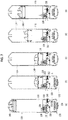
- Gerät (1000) zur Injektion flüssiger Arzneimittel mit einstellbarem Innendruck, umfassend:einen Zylinder (110), der ein Ende aufweist, an das eine Strömungsleitung (150) für flüssige Arzneimittel (150) angeschlossen ist, wobei an das andere Ende eine gaserzeugende Einheit (130) gekoppelt ist, wobei ein flüssiges Arzneimittel durch die Strömungsleitung (150) für flüssige Arzneimittel in den Zylinder (110) und aus diesem heraus strömt und die gaserzeugende Einheit (130) einen gaserzeugenden Raum (139) aufweist, in dem ein Gas erzeugt wird;einen Injektionskolben (140), der abdichtend in dem Zylinder (110) verschiebbar ist und einen Innenraum des Zylinders (110) in einen Speicherraum (114) für flüssige Arzneimittel und einen mit Gas versorgten Raum (116) unterteilt, wobei das flüssige Arzneimittel durch die Strömungsleitung (150) für flüssige Arzneimittel (150) strömt und den Speicherraum (114) für flüssige Arzneimittel füllt, und das Gas, das in der gaserzeugenden Einheit (130) erzeugt wird, dem mit Gas versorgten Raum (116) zugeführt wird;dadurch gekennzeichnet ist, dass es ein Umschaltglied (136) aufweist, das zwischen dem mit Gas versorgten Raum (116) und dem gaserzeugenden Raum (139) bereitgestellt ist, um beim Befüllen des Speicherraums (114) für flüssige Arzneimittel mit dem flüssigen Arzneimittel den mit Gas versorgten Raum (116) mit einer Atmosphäre zu verbinden und um beim Injizieren des flüssigen Arzneimittels den mit Gas versorgten Raum (116) mit dem gaserzeugenden Raum (139) zu verbinden, wobei das Umschaltglied (136) umfasst:einen Umschaltzylindern (310), der mit der Atmosphäre, dem mit Gas versorgten Raum (116) und dem gaserzeugenden Raum (139) in Verbindung steht; undeinen Umschaltkolben (320), der verschiebbar in dem Zylinder (310) angeordnet ist, um den mit Gas versorgten Raum (116) mit der Atmosphäre zu verbinden oder den mit Gas versorgten Raum (116) mit dem gaserzeugenden Raum (139) zu verbinden, in Abhängigkeit davon, wo sich der Umschaltkolben (320) innerhalb des Umschaltzylinders (310) befindet; undwobei der Umschaltzylinder (310) umfasst:ein erstes Loch (311), das die Atmosphäre mit dem Inneren des Umschaltzylinders (310) verbindet;ein zweites Loch (312), das den gaserzeugenden Raum (139) und das Innere des Umschaltzylinders (310) miteinander verbindet (310); undein drittes Loch (313), das den mit Gas versorgten Raum (116) und das Innere des Umschaltzylinders (310) miteinander verbindet, wobei es sich zwischen dem ersten Loch (311) und dem zweiten Loch (312) befindet.
- Gerät (1000) zur Injektion flüssiger Arzneimittel mit einstellbarem Innendruck nach Anspruch 2, wobei der Umschaltkolben (320) sich beim Befüllen des Speicherraums (114) für flüssige Arzneimittel mit dem flüssigen Arzneimittel zwischen dem dritten Loch (313) und dem zweiten Loch (312) in dem Umschaltzylinder (310) befindet, um den mit Gas versorgten Raum (116) mit der Atmosphäre zu verbinden, und der Umschaltkolben (320) sich beim Injizieren des flüssigen Arzneimittels zwischen dem dritten Loch (313) und dem ersten Loch in dem Umschaltzylinder (310) befindet, um den mit Gas versorgten Raum (116) und den gaserzeugenden Raum (139) miteinander zu verbinden.
- Gerät (1000) zur Injektion flüssiger Arzneimittel mit einstellbarem Innendruck nach Anspruch 2 oder 3, wobei beim Injizieren des flüssigen Arzneimittels, wenn der Innendruck des mit Gas versorgten Raums (116) einen vorbestimmten Druckwert überschreitet, das Umschaltglied (136) durch einen Umgehungsdurchgang (315), der dazu dient, den mit Gas versorgten Raum (116) mit der Atmosphäre zu verbinden, eine Menge an Gas, die einem Überdruck entspricht, an einen Außenraum abgibt.
- Gerät (1000) zur Injektion flüssiger Arzneimittel mit einstellbarem Innendruck, umfassend:einen Zylinder (110), der ein Ende aufweist, an das eine Strömungsleitung (150) für flüssige Arzneimittel (150) angeschlossen ist, wobei an das andere Ende eine gaserzeugende Einheit (130) gekoppelt ist, wobei ein flüssiges Arzneimittel durch die Strömungsleitung (150) für flüssige Arzneimittel in den Zylinder (110) und aus diesem heraus strömt und die gaserzeugende Einheit (130) einen gaserzeugenden Raum (139) aufweist, in dem ein Gas erzeugt wird;einen Injektionskolben (140), der abdichtend in dem Zylinder (110) verschiebbar ist und einen Innenraum des Zylinders (110) in einen Speicherraum (114) für flüssige Arzneimittel und einen mit Gas versorgten Raum (116) unterteilt, wobei das flüssige Arzneimittel durch die Strömungsleitung (150) für flüssige Arzneimittel (150) strömt und den Speicherraum (114) für flüssige Arzneimittel füllt, und das Gas, das in der gaserzeugenden Einheit (130) erzeugt wird, dem mit Gas versorgten Raum (116) zugeführt wird;dadurch gekennzeichnet ist, dass es ein Umschaltglied (136) aufweist, das zwischen dem mit Gas versorgten Raum (116) und dem gaserzeugenden Raum (139) bereitgestellt ist, um beim Befüllen des Speicherraums (114) für flüssige Arzneimittel mit dem flüssigen Arzneimittel den mit Gas versorgten Raum (116) mit einer Atmosphäre zu verbinden und um beim Injizieren des flüssigen Arzneimittels den mit Gas versorgten Raum (116) mit dem gaserzeugenden Raum (139) zu verbinden, wobei das Umschaltglied (136) umfasst:einen Umschaltzylinder (310), der mit der Atmosphäre, dem mit Gas versorgten Raum (116) und dem gaserzeugendem Raum (139) in Verbindung steht, wobei er einen Umgehungsdurchgang (315) umfasst, der dazu dient, den mit Gas versorgten Raum (116) mit der Atmosphäre zu verbinden;einen Umschaltkolben (320), der verschiebbar in dem Zylinder (310) angeordnet ist, um den mit Gas versorgten Raum (116) mit der Atmosphäre zu verbinden oder den mit Gas versorgten Raum (116) mit dem gaserzeugenden Raum (139) in Verbindung zu bringen, in Abhängigkeit davon, wo sich der Umschaltkolben (320) innerhalb des Umschaltzylinders (310) befindet; undein elastisches Umschaltglied (330), das in dem Umschaltzylinder (310) bereitgestellt ist, wobei es sich zwischen der Atmosphäre und dem Umschaltkolben (320) befindet und dazu befähigt ist, einen elastischen Druck auf den Umschaltkolben (320) auszuüben, sodass der Umgehungsdurchgang (315) geschlossen wird, bevor der Innendruck des mit Gas versorgten Raums (116) während des Injizierens des flüssigen Arzneimittels einen vorbestimmten Druckwert überschreitet.
- Gerät (1000) zur Injektion flüssiger Arzneimittel mit einstellbarem Innendruck nach Anspruch 5, wobei der Umschaltzylinder (310) umfasst:ein erstes Loch (311), das die Atmosphäre mit dem Inneren des Umschaltzylinders (310) verbindet;ein zweites Loch (312), das den gaserzeugenden Raum (139) und das Innere des Umschaltzylinders (310) miteinander verbindet (310); undein drittes Loch (313), das den mit Gas versorgten Raum (116) und das Innere des Umschaltzylinders (310) miteinander verbindet, wobei es sich zwischen dem ersten Loch (311) und dem zweiten Loch (312) befindet; undeinen abgestuften Bereich (316), der zwischen dem ersten Loch (311) und dem dritten Loch (313) gebildet ist, wobei er den Umgehungsdurchgang (315) bildet, der mit dem ersten Loch (311) verbunden ist.
- Gerät (1000) zur Injektion flüssiger Arzneimittel mit einstellbarem Innendruck nach Anspruch 6,
wobei sich der Umschaltkolben (320) beim Befüllen des Speicherraums (114) für flüssige Arzneimittel mit dem flüssigen Arzneimittel zwischen dem dritten Loch (313) und dem zweiten Loch (312) in dem Umschaltzylinder (310) befindet, um den mit Gas versorgten Raum (116) mit der Atmosphäre zu verbinden;
wobei sich der Umschaltkolben (320) beim Injizieren des flüssigen Arzneimittels zwischen dem dritten Loch (313) und dem abgestuften Bereich (316) in dem Umschaltzylinder (310) befindet, um den mit Gas versorgten Raum (116) mit dem gaserzeugenden Raum (139) zu verbinden; und
wobei sich der Umschaltkolben (320), wenn der Innendruck des mit Gas versorgten Raums (116) während des Injizierens des flüssigen Arzneimittels einen vorbestimmten Druckwert überschreitet, zwischen dem ersten Loch (311) und dem abgestuften Bereich (316) in dem Umschaltzylinder (310) befindet, sodass der Umgehungsdurchgang (315) geöffnet wird, um den mit Gas versorgten Raum (116) mit der Atmosphäre zu verbinden. - Gerät (1000) zur Injektion flüssiger Arzneimittel mit einstellbarem Innendruck nach Anspruch 6 oder 7, wobei der Abstand vom ersten Loch (311) bis zum abgestuften Bereich (316) kleiner als die Länge des elastischen Umschaltglieds (330) oder kleiner als die Summe der Länge des elastischen Umschaltglieds (330) und der Länge des Umschaltkolbens (320) ist.
- Gerät (1000') zur Injektion flüssiger Arzneimittel mit einstellbarem Innendruck nach Anspruch 1, wobei das Sperrventil (320') ein vorderes Ende (322'), das dem Raum (222) zum Einströmen von Außenluft zugewandt ist, und einen Körperabschnitt (324) aufweist, der abdichtend entlang einer Führungswand (242) des innenliegenden Verbindungsdurchgangs (220) verschiebbar ist, wobei es derart gebildet ist, dass es einen Durchlass (327) aufweist, der sich von einem Durchgangsloch (326) des vorderen Endes (322') zu einem Durchgangsloch (328) erstreckt, das in einer Seitenfläche des Körperabschnitts (324) gebildet ist.
- Gerät (1000') zur Injektion flüssiger Arzneimittel mit einstellbarem Innendruck nach Anspruch 9, wobei die Führungswand (242) des innenliegenden Verbindungsdurchgangs (220) derart gebildet ist, dass sie ein Durchgangsloch (240) aufweist, das dazu dient, eine Verbindung zwischen dem innenliegenden Verbindungsdurchgang (220) und dem mit Gas versorgten Raum (116) herzustellen.
- Gerät (1000') zur Injektion flüssiger Arzneimittel mit einstellbarem Innendruck nach Anspruch 10, wobei das Durchgangsloch (328), das in der Seitenfläche des Körperabschnitts (324) des Sperrventils (320') gebildet ist, wenn der Speicherraum (114) für flüssige Arzneimittel mit dem flüssigen Arzneimittel befüllt wird, bevor in der gaserzeugenden Einheit (130) das Gas erzeugt wird, sich an einer Stelle befindet, an der es mit dem Durchgangsloch (240) des innenliegenden Verbindungsdurchgangs (220) fluchtet, und wobei die Außenluft, die von dem Einlass (135) für Außenluft in den Raum (222) zum Einströmen von Außenluft strömt, durch das Durchgangsloch (326) des vorderen Endes (322'), den Durchlass (327) und das Durchgangsloch (328) strömt, das in der Seitenfläche des Körperabschnitts (324) gebildet ist, woraufhin sie durch das Durchgangsloch (240) des innenliegenden Verbindungsdurchgangs (220), das mit dem Durchgangsloch (328) fluchtet, das in der Seitenfläche des Körperabschnitts (324) gebildet ist, in den mit Gas versorgten Raum (116) strömt.
- Gerät (1000') zur Injektion flüssiger Arzneimittel mit einstellbarem Innendruck nach Anspruch 9 oder 10, wobei ein Ende des Raums (222) zum Einströmen von Außenluft des innenliegenden Verbindungsdurchgangs (220) geöffnet ist und das Gerät (1000') weiterhin ein Dichtungsglied (380) umfasst, um das geöffnete Ende abzudichten.
- Gerät (1000') zur Injektion flüssiger Arzneimittel mit einstellbarem Innendruck nach Anspruch 12, wobei das Gas, das in der gaserzeugenden Einheit (130) erzeugt wird, im Falle einer Injektion des flüssigen Arzneimittels nach dem Erzeugen des Gases in der gaserzeugenden Einheit (130), durch einen Gasströmungsdurchgang (260), der dazu dient, die gaserzeugende Einheit (130) mit dem Raum (224) zum Einströmen von erzeugtem Gas zu verbinden, derart in den Raum (224) zum Einströmen von erzeugtem Gas strömt, dass es auf einen rückwärtigen Bereich des Körperabschnitts (324) des Sperrventils (320') drückt; wobei weiterhin das Sperrventil (320') in Richtung des Raums (222) zum Einströmen von Außenluft bewegt wird, sodass das vordere Ende (322') des Sperrventils (320') mit dem Dichtungsglied (380) in Kontakt gebracht wird, um auf diese Weise zu verhindern, dass Außenlauft, die aus dem Einlass (135) für Außenluft stammt, durch das Durchgangsloch (326) des vorderen Endes (322') des Sperrventils (320') strömt.
Applications Claiming Priority (3)
| Application Number | Priority Date | Filing Date | Title |
|---|---|---|---|
| KR1020160045959A KR101697980B1 (ko) | 2016-04-15 | 2016-04-15 | 약액 충전 및 주입 모드에 따라 내부압력 조절이 가능한 약액주입장치 |
| KR1020160144456A KR101857730B1 (ko) | 2016-11-01 | 2016-11-01 | 내부압력 조절이 가능한 약액주입장치 |
| PCT/KR2017/003912 WO2017179887A1 (ko) | 2016-04-15 | 2017-04-11 | 내부압력 조절이 가능한 약액주입장치 |
Publications (3)
| Publication Number | Publication Date |
|---|---|
| EP3434299A1 EP3434299A1 (de) | 2019-01-30 |
| EP3434299A4 EP3434299A4 (de) | 2019-11-20 |
| EP3434299B1 true EP3434299B1 (de) | 2021-03-31 |
Family
ID=60042587
Family Applications (1)
| Application Number | Title | Priority Date | Filing Date |
|---|---|---|---|
| EP17782642.7A Active EP3434299B1 (de) | 2016-04-15 | 2017-04-11 | Medizinische fluidinjektionsvorrichtung zur einstellung des innendrucks |
Country Status (7)
| Country | Link |
|---|---|
| US (1) | US10960133B2 (de) |
| EP (1) | EP3434299B1 (de) |
| JP (1) | JP6745356B2 (de) |
| CN (1) | CN109152880B (de) |
| BR (1) | BR112018070965B1 (de) |
| IL (1) | IL261823B (de) |
| WO (1) | WO2017179887A1 (de) |
Families Citing this family (6)
| Publication number | Priority date | Publication date | Assignee | Title |
|---|---|---|---|---|
| IL287966B2 (en) * | 2019-07-02 | 2025-10-01 | Regeneron Pharma | Auto-injector and accompanying methods of use |
| CN110201265B (zh) * | 2019-07-10 | 2021-06-11 | 安徽医科大学 | 输液装置 |
| KR102373991B1 (ko) * | 2019-10-18 | 2022-03-15 | 김용현 | 약액 주입 장치 및 약액 주입 준비 방법 |
| CN110604850B (zh) * | 2019-10-28 | 2024-08-27 | 广东安特医疗有限公司 | 三通阀和输液装置 |
| CN115154762B (zh) * | 2022-07-27 | 2024-03-08 | 重庆倍加医疗器械有限公司 | 一种气压驱动注射器 |
| CN117531096B (zh) * | 2023-10-10 | 2026-01-23 | 复旦大学附属中山医院 | 一种高流量定压液体推进泵 |
Family Cites Families (16)
| Publication number | Priority date | Publication date | Assignee | Title |
|---|---|---|---|---|
| JPS52152989U (de) * | 1976-05-18 | 1977-11-19 | ||
| FR2355037A1 (fr) | 1976-06-14 | 1978-01-13 | Texaco Development Corp | Complexe d'un polymethacrylate ou d'un polymethacrylamide et d'un poly(alcene-1) liquide |
| JPS6139154Y2 (de) * | 1980-03-25 | 1986-11-11 | ||
| JPS56141274A (en) | 1980-04-04 | 1981-11-04 | Mitsubishi Electric Corp | Counter for number of use of elevator |
| US4773900A (en) * | 1986-08-20 | 1988-09-27 | Cochran Ulrich D | Infusion device |
| US6530900B1 (en) | 1997-05-06 | 2003-03-11 | Elan Pharma International Limited | Drug delivery device |
| DE19805478C2 (de) * | 1998-02-11 | 2001-06-21 | Daimler Chrysler Ag | 3/3-Wegeventil |
| US6413238B1 (en) * | 1999-09-17 | 2002-07-02 | Baxter International Inc | Fluid dispenser with stabilized fluid flow |
| AU2001222342A1 (en) | 2000-07-22 | 2002-02-18 | Yong-Nyun Kim | Liquid supply apparatus |
| EP2554196B1 (de) | 2000-11-30 | 2018-10-17 | Valeritas, Inc. | Flüssigkeitsabgabe- und -messsysteme |
| US7195610B1 (en) * | 2001-09-17 | 2007-03-27 | Cardinal Health 303, Inc. | Pneumatic syringe driver |
| KR100472577B1 (ko) | 2001-11-02 | 2005-02-22 | 김용년 | 액체공급장치 |
| KR100507593B1 (ko) * | 2002-02-08 | 2005-08-10 | 주식회사 이화양행 | 액체공급장치 |
| WO2007062182A2 (en) | 2005-11-23 | 2007-05-31 | Eksigent Technologies, Llp | Electrokinetic pump designs and drug delivery systems |
| US20080147007A1 (en) * | 2006-12-19 | 2008-06-19 | Toby Freyman | Delivery device with pressure control |
| KR101697980B1 (ko) | 2016-04-15 | 2017-01-19 | (주)이화바이오메딕스 | 약액 충전 및 주입 모드에 따라 내부압력 조절이 가능한 약액주입장치 |
-
2017
- 2017-04-11 WO PCT/KR2017/003912 patent/WO2017179887A1/ko not_active Ceased
- 2017-04-11 JP JP2018554433A patent/JP6745356B2/ja active Active
- 2017-04-11 US US16/090,476 patent/US10960133B2/en active Active
- 2017-04-11 BR BR112018070965-4A patent/BR112018070965B1/pt not_active IP Right Cessation
- 2017-04-11 CN CN201780023798.3A patent/CN109152880B/zh active Active
- 2017-04-11 EP EP17782642.7A patent/EP3434299B1/de active Active
-
2018
- 2018-09-17 IL IL261823A patent/IL261823B/en unknown
Non-Patent Citations (1)
| Title |
|---|
| None * |
Also Published As
| Publication number | Publication date |
|---|---|
| BR112018070965A2 (pt) | 2019-01-29 |
| BR112018070965B1 (pt) | 2023-04-11 |
| EP3434299A4 (de) | 2019-11-20 |
| CN109152880A (zh) | 2019-01-04 |
| US20190111205A1 (en) | 2019-04-18 |
| CN109152880B (zh) | 2021-02-02 |
| IL261823A (en) | 2018-10-31 |
| US10960133B2 (en) | 2021-03-30 |
| JP6745356B2 (ja) | 2020-08-26 |
| EP3434299A1 (de) | 2019-01-30 |
| WO2017179887A1 (ko) | 2017-10-19 |
| IL261823B (en) | 2022-04-01 |
| JP2019511335A (ja) | 2019-04-25 |
Similar Documents
| Publication | Publication Date | Title |
|---|---|---|
| EP3434299B1 (de) | Medizinische fluidinjektionsvorrichtung zur einstellung des innendrucks | |
| EP3492127B1 (de) | Vorrichtung zur injektion einer medizinischen flüssigkeit für die injektion zusätzlicher flüssigkeit nach abschluss der injektion einer medizinischen flüssigkeit | |
| JP3718167B2 (ja) | 充填済みアンプル内に入った液体を注入するための無針式シリンジ | |
| KR101857730B1 (ko) | 내부압력 조절이 가능한 약액주입장치 | |
| ES2535617T3 (es) | Jeringa para anestesia con un émbolo de avance que se desplaza longitudinalmente, así como una válvula de retención con dirección de avance y retroceso | |
| EP2694139B1 (de) | Stabanordnung mit einem nadellosen injektor | |
| JP2004500933A (ja) | 爆発式駆動装置を備えた無針式注射装置 | |
| KR101697980B1 (ko) | 약액 충전 및 주입 모드에 따라 내부압력 조절이 가능한 약액주입장치 | |
| JP2023538864A (ja) | シリンジ用のプライムチューブ構成 | |
| KR20190018149A (ko) | 공압식 파워 팩을 갖춘 약물 전달 장치 | |
| JP4512241B2 (ja) | 薬液のワンショット注入器および薬液注入装置 | |
| US12042626B2 (en) | Status indicator of a drug delivery system | |
| CN105764544B (zh) | 药物输送装置 | |
| US20080091148A1 (en) | Combined container-syringe | |
| HK40001551A (en) | Medicinal fluid injection device capable of adjusting internal pressure | |
| HK40001551B (zh) | 内部压力可调节的液体药物注射装置 | |
| KR102018909B1 (ko) | 약액주입장치에 사용되는 기체포집부재 및 이를 포함하는 약액주입장치 | |
| KR101739608B1 (ko) | 주입 용구 및 이를 갖춘 액약 주입 시스템 | |
| KR100710921B1 (ko) | 액체 공급 장치 | |
| HK40008721A (en) | Liquid medicine injection apparatus capable of injecting additional fluid after completion of liquid medicine injection | |
| HK40042855A (en) | Gas-capturing member used in liquid medince injection apparatus and liquid medince injection apparatus including the same | |
| HK1194698B (en) | Needleless injector wand assembly | |
| HK40008721B (zh) | 能够在液体药物注入完成後注入额外流体的液体药物注入装置 | |
| HK1194698A (en) | Needleless injector wand assembly |
Legal Events
| Date | Code | Title | Description |
|---|---|---|---|
| STAA | Information on the status of an ep patent application or granted ep patent |
Free format text: STATUS: THE INTERNATIONAL PUBLICATION HAS BEEN MADE |
|
| PUAI | Public reference made under article 153(3) epc to a published international application that has entered the european phase |
Free format text: ORIGINAL CODE: 0009012 |
|
| STAA | Information on the status of an ep patent application or granted ep patent |
Free format text: STATUS: REQUEST FOR EXAMINATION WAS MADE |
|
| 17P | Request for examination filed |
Effective date: 20181023 |
|
| AK | Designated contracting states |
Kind code of ref document: A1 Designated state(s): AL AT BE BG CH CY CZ DE DK EE ES FI FR GB GR HR HU IE IS IT LI LT LU LV MC MK MT NL NO PL PT RO RS SE SI SK SM TR |
|
| AX | Request for extension of the european patent |
Extension state: BA ME |
|
| DAV | Request for validation of the european patent (deleted) | ||
| DAX | Request for extension of the european patent (deleted) | ||
| A4 | Supplementary search report drawn up and despatched |
Effective date: 20191022 |
|
| RIC1 | Information provided on ipc code assigned before grant |
Ipc: A61M 5/315 20060101ALI20191016BHEP Ipc: A61M 5/145 20060101AFI20191016BHEP Ipc: A61M 5/168 20060101ALI20191016BHEP Ipc: A61M 5/142 20060101ALI20191016BHEP |
|
| GRAP | Despatch of communication of intention to grant a patent |
Free format text: ORIGINAL CODE: EPIDOSNIGR1 |
|
| STAA | Information on the status of an ep patent application or granted ep patent |
Free format text: STATUS: GRANT OF PATENT IS INTENDED |
|
| INTG | Intention to grant announced |
Effective date: 20201111 |
|
| GRAS | Grant fee paid |
Free format text: ORIGINAL CODE: EPIDOSNIGR3 |
|
| GRAA | (expected) grant |
Free format text: ORIGINAL CODE: 0009210 |
|
| STAA | Information on the status of an ep patent application or granted ep patent |
Free format text: STATUS: THE PATENT HAS BEEN GRANTED |
|
| AK | Designated contracting states |
Kind code of ref document: B1 Designated state(s): AL AT BE BG CH CY CZ DE DK EE ES FI FR GB GR HR HU IE IS IT LI LT LU LV MC MK MT NL NO PL PT RO RS SE SI SK SM TR |
|
| REG | Reference to a national code |
Ref country code: GB Ref legal event code: FG4D Ref country code: CH Ref legal event code: EP |
|
| REG | Reference to a national code |
Ref country code: DE Ref legal event code: R096 Ref document number: 602017035794 Country of ref document: DE Ref country code: AT Ref legal event code: REF Ref document number: 1376220 Country of ref document: AT Kind code of ref document: T Effective date: 20210415 |
|
| REG | Reference to a national code |
Ref country code: IE Ref legal event code: FG4D |
|
| REG | Reference to a national code |
Ref country code: LT Ref legal event code: MG9D |
|
| PG25 | Lapsed in a contracting state [announced via postgrant information from national office to epo] |
Ref country code: BG Free format text: LAPSE BECAUSE OF FAILURE TO SUBMIT A TRANSLATION OF THE DESCRIPTION OR TO PAY THE FEE WITHIN THE PRESCRIBED TIME-LIMIT Effective date: 20210630 Ref country code: NO Free format text: LAPSE BECAUSE OF FAILURE TO SUBMIT A TRANSLATION OF THE DESCRIPTION OR TO PAY THE FEE WITHIN THE PRESCRIBED TIME-LIMIT Effective date: 20210630 Ref country code: FI Free format text: LAPSE BECAUSE OF FAILURE TO SUBMIT A TRANSLATION OF THE DESCRIPTION OR TO PAY THE FEE WITHIN THE PRESCRIBED TIME-LIMIT Effective date: 20210331 Ref country code: HR Free format text: LAPSE BECAUSE OF FAILURE TO SUBMIT A TRANSLATION OF THE DESCRIPTION OR TO PAY THE FEE WITHIN THE PRESCRIBED TIME-LIMIT Effective date: 20210331 |
|
| PG25 | Lapsed in a contracting state [announced via postgrant information from national office to epo] |
Ref country code: LV Free format text: LAPSE BECAUSE OF FAILURE TO SUBMIT A TRANSLATION OF THE DESCRIPTION OR TO PAY THE FEE WITHIN THE PRESCRIBED TIME-LIMIT Effective date: 20210331 Ref country code: RS Free format text: LAPSE BECAUSE OF FAILURE TO SUBMIT A TRANSLATION OF THE DESCRIPTION OR TO PAY THE FEE WITHIN THE PRESCRIBED TIME-LIMIT Effective date: 20210331 Ref country code: SE Free format text: LAPSE BECAUSE OF FAILURE TO SUBMIT A TRANSLATION OF THE DESCRIPTION OR TO PAY THE FEE WITHIN THE PRESCRIBED TIME-LIMIT Effective date: 20210331 |
|
| REG | Reference to a national code |
Ref country code: NL Ref legal event code: MP Effective date: 20210331 |
|
| REG | Reference to a national code |
Ref country code: AT Ref legal event code: MK05 Ref document number: 1376220 Country of ref document: AT Kind code of ref document: T Effective date: 20210331 |
|
| PG25 | Lapsed in a contracting state [announced via postgrant information from national office to epo] |
Ref country code: AT Free format text: LAPSE BECAUSE OF FAILURE TO SUBMIT A TRANSLATION OF THE DESCRIPTION OR TO PAY THE FEE WITHIN THE PRESCRIBED TIME-LIMIT Effective date: 20210331 Ref country code: SM Free format text: LAPSE BECAUSE OF FAILURE TO SUBMIT A TRANSLATION OF THE DESCRIPTION OR TO PAY THE FEE WITHIN THE PRESCRIBED TIME-LIMIT Effective date: 20210331 Ref country code: NL Free format text: LAPSE BECAUSE OF FAILURE TO SUBMIT A TRANSLATION OF THE DESCRIPTION OR TO PAY THE FEE WITHIN THE PRESCRIBED TIME-LIMIT Effective date: 20210331 Ref country code: CZ Free format text: LAPSE BECAUSE OF FAILURE TO SUBMIT A TRANSLATION OF THE DESCRIPTION OR TO PAY THE FEE WITHIN THE PRESCRIBED TIME-LIMIT Effective date: 20210331 Ref country code: EE Free format text: LAPSE BECAUSE OF FAILURE TO SUBMIT A TRANSLATION OF THE DESCRIPTION OR TO PAY THE FEE WITHIN THE PRESCRIBED TIME-LIMIT Effective date: 20210331 Ref country code: LT Free format text: LAPSE BECAUSE OF FAILURE TO SUBMIT A TRANSLATION OF THE DESCRIPTION OR TO PAY THE FEE WITHIN THE PRESCRIBED TIME-LIMIT Effective date: 20210331 |
|
| PG25 | Lapsed in a contracting state [announced via postgrant information from national office to epo] |
Ref country code: SK Free format text: LAPSE BECAUSE OF FAILURE TO SUBMIT A TRANSLATION OF THE DESCRIPTION OR TO PAY THE FEE WITHIN THE PRESCRIBED TIME-LIMIT Effective date: 20210331 Ref country code: RO Free format text: LAPSE BECAUSE OF FAILURE TO SUBMIT A TRANSLATION OF THE DESCRIPTION OR TO PAY THE FEE WITHIN THE PRESCRIBED TIME-LIMIT Effective date: 20210331 Ref country code: PL Free format text: LAPSE BECAUSE OF FAILURE TO SUBMIT A TRANSLATION OF THE DESCRIPTION OR TO PAY THE FEE WITHIN THE PRESCRIBED TIME-LIMIT Effective date: 20210331 Ref country code: PT Free format text: LAPSE BECAUSE OF FAILURE TO SUBMIT A TRANSLATION OF THE DESCRIPTION OR TO PAY THE FEE WITHIN THE PRESCRIBED TIME-LIMIT Effective date: 20210802 Ref country code: IS Free format text: LAPSE BECAUSE OF FAILURE TO SUBMIT A TRANSLATION OF THE DESCRIPTION OR TO PAY THE FEE WITHIN THE PRESCRIBED TIME-LIMIT Effective date: 20210731 |
|
| PG25 | Lapsed in a contracting state [announced via postgrant information from national office to epo] |
Ref country code: LU Free format text: LAPSE BECAUSE OF NON-PAYMENT OF DUE FEES Effective date: 20210411 |
|
| REG | Reference to a national code |
Ref country code: DE Ref legal event code: R097 Ref document number: 602017035794 Country of ref document: DE |
|
| REG | Reference to a national code |
Ref country code: BE Ref legal event code: MM Effective date: 20210430 |
|
| PG25 | Lapsed in a contracting state [announced via postgrant information from national office to epo] |
Ref country code: ES Free format text: LAPSE BECAUSE OF FAILURE TO SUBMIT A TRANSLATION OF THE DESCRIPTION OR TO PAY THE FEE WITHIN THE PRESCRIBED TIME-LIMIT Effective date: 20210331 Ref country code: AL Free format text: LAPSE BECAUSE OF FAILURE TO SUBMIT A TRANSLATION OF THE DESCRIPTION OR TO PAY THE FEE WITHIN THE PRESCRIBED TIME-LIMIT Effective date: 20210331 Ref country code: CH Free format text: LAPSE BECAUSE OF NON-PAYMENT OF DUE FEES Effective date: 20210430 Ref country code: DK Free format text: LAPSE BECAUSE OF FAILURE TO SUBMIT A TRANSLATION OF THE DESCRIPTION OR TO PAY THE FEE WITHIN THE PRESCRIBED TIME-LIMIT Effective date: 20210331 Ref country code: MC Free format text: LAPSE BECAUSE OF FAILURE TO SUBMIT A TRANSLATION OF THE DESCRIPTION OR TO PAY THE FEE WITHIN THE PRESCRIBED TIME-LIMIT Effective date: 20210331 Ref country code: LI Free format text: LAPSE BECAUSE OF NON-PAYMENT OF DUE FEES Effective date: 20210430 |
|
| PLBE | No opposition filed within time limit |
Free format text: ORIGINAL CODE: 0009261 |
|
| STAA | Information on the status of an ep patent application or granted ep patent |
Free format text: STATUS: NO OPPOSITION FILED WITHIN TIME LIMIT |
|
| 26N | No opposition filed |
Effective date: 20220104 |
|
| PG25 | Lapsed in a contracting state [announced via postgrant information from national office to epo] |
Ref country code: IE Free format text: LAPSE BECAUSE OF NON-PAYMENT OF DUE FEES Effective date: 20210411 |
|
| PG25 | Lapsed in a contracting state [announced via postgrant information from national office to epo] |
Ref country code: IS Free format text: LAPSE BECAUSE OF FAILURE TO SUBMIT A TRANSLATION OF THE DESCRIPTION OR TO PAY THE FEE WITHIN THE PRESCRIBED TIME-LIMIT Effective date: 20210731 |
|
| PG25 | Lapsed in a contracting state [announced via postgrant information from national office to epo] |
Ref country code: BE Free format text: LAPSE BECAUSE OF NON-PAYMENT OF DUE FEES Effective date: 20210430 |
|
| PG25 | Lapsed in a contracting state [announced via postgrant information from national office to epo] |
Ref country code: CY Free format text: LAPSE BECAUSE OF FAILURE TO SUBMIT A TRANSLATION OF THE DESCRIPTION OR TO PAY THE FEE WITHIN THE PRESCRIBED TIME-LIMIT Effective date: 20210331 |
|
| PG25 | Lapsed in a contracting state [announced via postgrant information from national office to epo] |
Ref country code: HU Free format text: LAPSE BECAUSE OF FAILURE TO SUBMIT A TRANSLATION OF THE DESCRIPTION OR TO PAY THE FEE WITHIN THE PRESCRIBED TIME-LIMIT; INVALID AB INITIO Effective date: 20170411 Ref country code: GR Free format text: LAPSE BECAUSE OF FAILURE TO SUBMIT A TRANSLATION OF THE DESCRIPTION OR TO PAY THE FEE WITHIN THE PRESCRIBED TIME-LIMIT Effective date: 20210331 |
|
| PG25 | Lapsed in a contracting state [announced via postgrant information from national office to epo] |
Ref country code: MK Free format text: LAPSE BECAUSE OF FAILURE TO SUBMIT A TRANSLATION OF THE DESCRIPTION OR TO PAY THE FEE WITHIN THE PRESCRIBED TIME-LIMIT Effective date: 20210331 |
|
| PG25 | Lapsed in a contracting state [announced via postgrant information from national office to epo] |
Ref country code: TR Free format text: LAPSE BECAUSE OF FAILURE TO SUBMIT A TRANSLATION OF THE DESCRIPTION OR TO PAY THE FEE WITHIN THE PRESCRIBED TIME-LIMIT Effective date: 20210331 |
|
| PG25 | Lapsed in a contracting state [announced via postgrant information from national office to epo] |
Ref country code: MT Free format text: LAPSE BECAUSE OF FAILURE TO SUBMIT A TRANSLATION OF THE DESCRIPTION OR TO PAY THE FEE WITHIN THE PRESCRIBED TIME-LIMIT Effective date: 20210331 |
|
| PGFP | Annual fee paid to national office [announced via postgrant information from national office to epo] |
Ref country code: DE Payment date: 20250430 Year of fee payment: 9 |
|
| PGFP | Annual fee paid to national office [announced via postgrant information from national office to epo] |
Ref country code: GB Payment date: 20250423 Year of fee payment: 9 |
|
| PGFP | Annual fee paid to national office [announced via postgrant information from national office to epo] |
Ref country code: IT Payment date: 20250424 Year of fee payment: 9 |
|
| PGFP | Annual fee paid to national office [announced via postgrant information from national office to epo] |
Ref country code: FR Payment date: 20250425 Year of fee payment: 9 |