EP3434097B1 - Halmteiler für den erntevorsatz einer landwirtschaftlichen erntemaschine mit mehreren erntehaspeln - Google Patents
Halmteiler für den erntevorsatz einer landwirtschaftlichen erntemaschine mit mehreren erntehaspeln Download PDFInfo
- Publication number
- EP3434097B1 EP3434097B1 EP18185995.0A EP18185995A EP3434097B1 EP 3434097 B1 EP3434097 B1 EP 3434097B1 EP 18185995 A EP18185995 A EP 18185995A EP 3434097 B1 EP3434097 B1 EP 3434097B1
- Authority
- EP
- European Patent Office
- Prior art keywords
- reel
- header
- crop divider
- crop
- reels
- Prior art date
- Legal status (The legal status is an assumption and is not a legal conclusion. Google has not performed a legal analysis and makes no representation as to the accuracy of the status listed.)
- Active
Links
- 238000003306 harvesting Methods 0.000 title description 23
- 230000000712 assembly Effects 0.000 claims description 6
- 238000000429 assembly Methods 0.000 claims description 6
- 239000000463 material Substances 0.000 description 8
- 241000239290 Araneae Species 0.000 description 6
- 235000013339 cereals Nutrition 0.000 description 6
- 241000196324 Embryophyta Species 0.000 description 5
- 230000007246 mechanism Effects 0.000 description 4
- 238000003466 welding Methods 0.000 description 3
- 244000068988 Glycine max Species 0.000 description 2
- 235000010469 Glycine max Nutrition 0.000 description 2
- 241000209140 Triticum Species 0.000 description 2
- 235000021307 Triticum Nutrition 0.000 description 2
- 239000000853 adhesive Substances 0.000 description 2
- 230000001070 adhesive effect Effects 0.000 description 2
- 241001124569 Lycaenidae Species 0.000 description 1
- 238000004140 cleaning Methods 0.000 description 1
- 238000010276 construction Methods 0.000 description 1
- 230000008676 import Effects 0.000 description 1
- 230000006698 induction Effects 0.000 description 1
- 230000002123 temporal effect Effects 0.000 description 1
- 230000003245 working effect Effects 0.000 description 1
Images

Classifications
-
- A—HUMAN NECESSITIES
- A01—AGRICULTURE; FORESTRY; ANIMAL HUSBANDRY; HUNTING; TRAPPING; FISHING
- A01D—HARVESTING; MOWING
- A01D41/00—Combines, i.e. harvesters or mowers combined with threshing devices
- A01D41/12—Details of combines
- A01D41/14—Mowing tables
-
- A—HUMAN NECESSITIES
- A01—AGRICULTURE; FORESTRY; ANIMAL HUSBANDRY; HUNTING; TRAPPING; FISHING
- A01D—HARVESTING; MOWING
- A01D57/00—Delivering mechanisms for harvesters or mowers
- A01D57/01—Devices for leading crops to the mowing apparatus
- A01D57/02—Devices for leading crops to the mowing apparatus using reels
-
- A—HUMAN NECESSITIES
- A01—AGRICULTURE; FORESTRY; ANIMAL HUSBANDRY; HUNTING; TRAPPING; FISHING
- A01D—HARVESTING; MOWING
- A01D41/00—Combines, i.e. harvesters or mowers combined with threshing devices
- A01D41/12—Details of combines
- A01D41/14—Mowing tables
- A01D41/142—Header drives
-
- A—HUMAN NECESSITIES
- A01—AGRICULTURE; FORESTRY; ANIMAL HUSBANDRY; HUNTING; TRAPPING; FISHING
- A01D—HARVESTING; MOWING
- A01D57/00—Delivering mechanisms for harvesters or mowers
- A01D57/01—Devices for leading crops to the mowing apparatus
- A01D57/02—Devices for leading crops to the mowing apparatus using reels
- A01D57/03—Devices for leading crops to the mowing apparatus using reels with supplementary controlled movement of the crop-engaging members, e.g. of the tines
-
- A—HUMAN NECESSITIES
- A01—AGRICULTURE; FORESTRY; ANIMAL HUSBANDRY; HUNTING; TRAPPING; FISHING
- A01D—HARVESTING; MOWING
- A01D63/00—Outside dividers
- A01D63/04—Non-rotating dividers
Definitions
- the exemplary embodiments of the present invention relate generally to a harvesting reel assembly for a header of a plant cutting machine (e.g., a combine harvester) and, more specifically, to a center crop divider of a harvesting reel assembly header that resists ingress of crop material between adjacent reels of the harvesting reel assembly.
- a plant cutting machine e.g., a combine harvester
- An agricultural harvester e.g., a plant cutting machine, such as, but not limited to, a combine or a windrower, generally includes a header operable for severing and collecting plant or crop material as the harvester is driven over a crop field.
- the header has a plant cutting mechanism for severing the plants or crops, such as an elongate sickle mechanism that reciprocates sidewardly relative to a non-reciprocating guard structure or a row unit with gathering chains and deck plates.
- the header also includes a harvesting reel assembly.
- Harvesting reel assemblies such as a pickup reel, a draper reel and a gathering reel, are used on agricultural harvesters to guide the crop to the cutting mechanism and onto a feeding apparatus.
- the harvesting reel assembly includes a plurality of reel members, i.e., tine bars, extending widthwise across the harvesting reel assembly with the tines extending outwardly therefrom to engage crop material as the tines are rotated about a rotational axis.
- the reel members follow a cam track that guides the position of the tines.
- the present disclosure provides a multiple reel header for an agricultural harvester having a crop divider.
- a header for an agricultural harvester including a frame.
- the header comprises a reel assembly including a first reel and a second reel spaced from the first reel a fixed distance, and reel support structure supporting the first and second reels for movement between first and second positions.
- the header further includes a crop divider connected to the reel support structure.
- the reel support structure comprises a first cam assembly engaged with the first reel and a second cam assembly engaged with the second reel, and the crop divider extends between the first and second cam assemblies to substantially span the width of the fixed distance.
- the crop divider includes a beveled face including a central ridge flanked by rearwardly directed walls. Another aspect of the exemplary embodiment is that the rearwardly directed walls are convex. Another aspect of the exemplary embodiment is that the crop divider is elongated and curved. Another aspect of the exemplary embodiment is that the crop divider is positioned forwardly of the fixed distance and is connected to a forward end of the reel support structure.
- the crop divider is spaced from a bottom of the reel assembly.
- the crop divider extends from a bottom portion of the support structure to about a most forward end of the support structure.
- the present disclosure thus provides a reel assembly having a crop divider disposed across the width of the fixed spacing between adjacent harvesting reels that diverts the crop being cut away from the gap between the harvesting reels and into the paths of the rotating reels whereby it may be effectively collected by the reels.
- the center crop divider substantially spans a width of the fixed distance between first and second adjacent reels and is connected to the reel support structure supporting the first and second reels for movement between first and second positions, whereby the crop divider moves in unison with the reel assembly between those positions.
- the crop divider When used in combination with a multiple reel agricultural harvester header, it overcomes one more of the disadvantages of conventional headers by providing structure for effectively diverting crop material into the rotating reels whereby it may be effectively collected by the reels and not become unharvested or cause clogging between the reels.
- grain refers to that part of a crop which is harvested and separated from discardable portions of the crop material.
- header of the subject disclosure is applicable to a variety of crops, including but not limited to wheat, soybeans and small grains.
- debris material other than grain, and the like are used interchangeably.
- range format various aspects of the subject disclosure can be presented in a range format. It should be understood that the description in range format is merely for convenience and brevity and should not be construed as an inflexible limitation on the scope of the subject disclosure. Accordingly, the description of a range should be considered to have specifically disclosed all the possible subranges as well as individual numerical values within that range. For example, description of a range such as from 1 to 6 should be considered to have specifically disclosed subranges such as from 1 to 3, from 1 to 4, from 1 to 5, from 2 to 4, from 2 to 6, from 3 to 6 etc., as well as individual numbers within that range, for example, 1, 2, 2.7, 3, 4, 5, 5.3, and 6. This applies regardless of the breadth of the range.
- identical or substantially similar elements of the subject disclosure such as a plurality of reels 200R and 200L may be described with reference to only one of those elements, such as the reel 200R. It is appreciated therefore that the description of one element is equally applicable to the remainder of the same elements.
- identical elements, or substantially identical elements where so indicated will be identified, where appropriate, by the same reference numeral, e.g., 200, and distinguished by an alphabetical letter, e.g., R, L, etc.
- the reel 200R is one of the reels and the reel 200L is another of the reels.
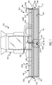
- FIGS. 1-5 illustrate an agricultural harvester 100 in accordance with an exemplary embodiment.
- the agricultural harvester is illustrated as a combine harvester.
- the harvester 100 comprises a header 102 and a cab 104 for an operator of the harvester.
- the header 102 includes a frame 106, reel support structure 300 (further described below) connected to the frame 106 and a harvesting reel assembly 202.
- the frame 106 is the structural chassis of the header 102 and allows for the various components of the header 102 to be attached thereto.
- the header 102 is attached to a forward end of the harvester 100, and is configured to cut crops, including (without limitation) small grains (e.g., wheat, soybeans, grain, etc.), and to induct the cut crops into a feederhouse 109 as the harvester 100 moves forward over a crop field.
- small grains e.g., wheat, soybeans, grain, etc.
- the header 102 includes a floor 104 that is supported in desired proximity to a surface of a crop field and a cutter bar 110.
- the cutter bar 110 of the header 102 extends transversely along a forward edge of the floor 104 i.e., in a widthwise direction of the harvester 100, and is bound by a first side edge 112 and an opposing second side edge 114, which are both adjacent to the floor 104.
- the cutter bar 110 is configured to cut crops in preparation for induction into the feederhouse 109. It is appreciated that the cutter bar 110 includes one or more reciprocating sickles such as those disclosed in U.S. Patent No. 8,151,547 .
- the elongated and rotatable harvesting reel assembly 202 extends above and in close proximity to the cutter bar 110.
- the harvesting reel assembly 202 is typically configured to cooperate with a plurality of draper belts, such as lateral draper belts and infeed draper belts (not illustrated), for conveying cut crops to the feederhouse 109, for threshing and cleaning.
- the header 102 may include a rotatable auger, i.e. a conveyor screw (not illustrated), to facilitate feeding into the feederhouse 109. While the foregoing aspects of the harvester 100 are being described with respect to the header 102 shown, the harvesting reel assembly 202 of the subject disclosure can be applied to any other header having use for such a reel assembly. It is understood that, unless otherwise specified, the right side of the harvesting reel assembly 202 is substantially structurally similar to the left side.
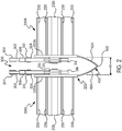
- the harvesting reel assembly 202 comprises at least a pair of harvesting reels or, simply, first and second reels 200L, 200R which include at least a pair of spaced apart reel spiders 210L, 210R engaged on rotatable shafts or axles 212L, 212R supported at their outer ends 214L, 214R by outboard supports 216L, 216R for rotation about a reel axis 218.
- the spiders 210L, 210R in turn support a plurality of pivotally moveable tine bars 220 (the tines of which are not illustrated) which orbit about reel axis 218 as the spiders rotate about the reel axis. Additional spiders may be intermediately positioned between the outboard spiders for additional tine bar support in wider reels.
- the first reel 200L and the second reel 200R are spaced apart from one another a fixed distance "W".
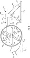
- At the innermost ends of reels 200L, 200R are spiders 210L, 210R, one of which is shown in Fig. 3 , that carry tine bars 220 fitted at their ends with cams (not illustrated).
- the cams in turn engage a cam assembly 222 that is part of the reel support structure, described below, and is operatively engaged with and between the first and second reels.
- the cams follow the cam assembly and rotate the tine bars 220 and the tines carried thereby as the reels 200R, 200L rotate about shafts 212L, 212R, whereby the angle of the tines is varied by pivotal movement of the tine bars 220 to angularly orient the tines for most effective crop movement.
- the reel support structure 300 supports the reels 200L, 200R and further includes mechanisms for moving the reels in fore and aft and vertical directions, whereby the reels may move between any number of first and second positions.
- the header comprises at least a first extensible actuator 310 operably connected to the reel support structure for moving the first and second reels in vertical directions and at least a second extensible actuator 324 operably connected to the reel support structure for moving the first and second reels in fore and aft directions.
- reel support structure 300 includes a brace 302 pivotably mounted to header frame 106 at a pivot 304.
- brace 302 is fixedly connected to a first bracket 306.
- first bracket 306 Pivotably connected to first bracket 306 is one end 308 of a first extensible actuator 310 such as a hydraulic cylinder or the like, the opposite end 312 of which is connected to header frame 106.
- first bracket 306 Also fixedly connected to first bracket 306 is one end 314 of a reel arm 316, the opposite end 318 of which is slidably received in a second bracket 320.
- the lower end of second bracket 320 rotatably receives an end of the reel shaft.
- a second extensible actuator 324 such as a hydraulic cylinder or the like, the opposite end 326 of which is connected to the second bracket 320. So constructed and arranged, extension and retraction of the first extensible actuator 310 raises and lowers its respective reel 220L or 200R in a vertical direction, whereas extension and retraction of second extensible actuator 324 moves its respective reel 220L or 200R in fore and aft directions.
- cam assembly 222 includes a first cam assembly 222A engaged with the first reel 200L and a second cam assembly 222B engaged with the second reel 200R, whereby the first and second cam assemblies 222A, 222B define a fixed distance "W".
- the crop divider 400 is positioned forwardly of the fixed distance and extends between the first and second cam assemblies.
- the crop divider 400 may be fixedly connected to the cam assemblies 222A, 222B by welding, riveting, adhesives or the like.
- the crop divider may be releasably connected to the cam assembly by mechanical fasteners such as screws, bolts, or the like.
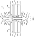
- a header 102' having the crop divider 400 connected to the support structure 300.
- the crop divider 400 may, e.g., be connected to the second brackets 320 by a pair of third brackets 328L, 328R. More particularly, aft portions of third brackets are preferably affixed to the second brackets 320 by welding, riveting, bolting or the like, whereas fore ends of the third brackets define outwardly directed flanges 330L, 330R to which the crop divider 400 may be fixedly or releasably attached such as by welding, riveting, adhesives, or mechanical fasteners such as screws or bolts. Regardless of how the crop divider is connected to the support structure, the crop divider moves in unison with the first and second reels in the fore and aft directions and vertical directions and does not rotate with the first and second reels 200L, 200R.
- the crop divider 400 substantially spans the fixed distance "W", regardless of whether the fixed distance is established by the cam assembly 222 or the third brackets 328.
- the crop divider has a beveled face including a central ridge 402 flanked by rearwardly directed walls 404.
- the walls 404 are convex.
- the crop divider is elongated and curved and has a bottom 406 that is spaced a distance "d" from a bottom of the reel assembly.
- the crop divider extends generally from a bottom portion of the support structure to about a most forward end of the support structure.
- a header having one or more crop dividers constructed and arranged as described are apparent. Specifically, crop field harvesting efficiency can be significantly increased because crop is diverted to the left and right of the crop divider whereby it is effectively gathered by the harvesting reels for increased harvesting efficiency.
- the crop dividers prevent crop from gathering between the harvesting reels and clogging the moving parts therebetween, thereby improving harvesting operations and increasing the useful life of the header.
Landscapes
- Life Sciences & Earth Sciences (AREA)
- Environmental Sciences (AREA)
- Outside Dividers And Delivering Mechanisms For Harvesters (AREA)
Claims (10)
- Vorsatz (102) für eine landwirtschaftliche Erntemaschine (100), die einen Rahmen (106) aufweist, wobei der Vorsatz (102) umfasst:
eine Haspelanordnung (202) mit:einer ersten Haspel (200L) und einer zweiten Haspel (200R), die von der ersten Haspel (200L) um einen festen Abstand (W) beabstandet ist;einer Haspelträgerkonstruktion (300), die die ersten und zweiten Haspeln (200L, 200R) zur Bewegung zwischen einer ersten Stellung und einer zweiten Stellung trägt; undeinem Halmteiler (400), der mit der Haspelträgerkonstruktion (300) verbunden ist,wobei der Vorsatz (102) dadurch gekennzeichnet ist, dassdie Haspelträgerkonstruktion (300) eine erste Mitnehmeranordnung (222A), die mit der ersten Haspel (200L) in Eingriff steht, und eine zweite Mitnehmeranordnung (222B) aufweist, die mit der zweiten Haspel (200R) in Eingriff steht; und der Halmteiler (400) sich zwischen den ersten und zweiten Mitnehmeranordnungen (222A, 222B) erstreckt, um im Wesentlichen die Breite des festen Abstandes (W) zu überbrücken. - Vorsatz nach Anspruch 1, wobei der Halmteiler (400) eine abgeschrägte Vorderfläche umfasst.
- Vorsatz nach den Ansprüchen 12, wobei der Halmteiler (400) einen mittigen Firstabschnitt (402) umfasst, der von nach hinten gerichteten Wänden (404) flankiert ist.
- Vorsatz nach Anspruch 3, wobei die nach hinten gerichteten Wände (404) konvex sind.
- Vorsatz nach den Ansprüchen 1-4, wobei der Halmteiler (400) länglich und gekrümmt ist.
- Vorsatz nach den Ansprüchen 1-5, wobei der Halmteiler (400) von dem festen Abstand (W) nach vorne angeordnet ist.
- Vorsatz nach den Ansprüchen 1-6, wobei ein Boden (406) des Halmteilers (400) von einem Boden der Haspelanordnung (202) beabstandet ist.
- Vorsatz nach den Ansprüchen 1-7, wobei der Halmteiler (400) mit einem vorderen Ende der Haspelträgerkonstruktion (300) verbunden ist.
- Vorsatz nach den Ansprüchen 1-8, wobei der Halmteiler (400) sich von einem Bodenabschnitt der Trägerkonstruktion (300) bis zu etwa einem vordersten Ende der Trägerkonstruktion (300) erstreckt.
- Vorsatz nach den Ansprüchen 1-9, wobei die erste Mitnehmeranordnung (222A) von der zweiten Mitnehmeranordnung (222B) beabstandet ist, wobei der feste Abstand (W) definiert wird.
Applications Claiming Priority (1)
| Application Number | Priority Date | Filing Date | Title |
|---|---|---|---|
| US15/663,056 US10368490B2 (en) | 2017-07-28 | 2017-07-28 | Crop divider for an agricultural harvester header having multiple harvesting reels |
Publications (2)
| Publication Number | Publication Date |
|---|---|
| EP3434097A1 EP3434097A1 (de) | 2019-01-30 |
| EP3434097B1 true EP3434097B1 (de) | 2020-09-09 |
Family
ID=63079788
Family Applications (1)
| Application Number | Title | Priority Date | Filing Date |
|---|---|---|---|
| EP18185995.0A Active EP3434097B1 (de) | 2017-07-28 | 2018-07-27 | Halmteiler für den erntevorsatz einer landwirtschaftlichen erntemaschine mit mehreren erntehaspeln |
Country Status (2)
| Country | Link |
|---|---|
| US (1) | US10368490B2 (de) |
| EP (1) | EP3434097B1 (de) |
Families Citing this family (3)
| Publication number | Priority date | Publication date | Assignee | Title |
|---|---|---|---|---|
| EP3669636B1 (de) * | 2018-12-20 | 2022-08-10 | CNH Industrial Belgium NV | Mähdrescherschneidwerk mit geteilter haspel |
| US20210274710A1 (en) * | 2020-03-05 | 2021-09-09 | Cnh Industrial America Llc | Variable speed reel drive for a header of an agricultural harvester |
| US20230309451A1 (en) * | 2022-03-30 | 2023-10-05 | Cnh Industrial America Llc | Center section reel for a header of an agricultural harvester |
Family Cites Families (25)
| Publication number | Priority date | Publication date | Assignee | Title |
|---|---|---|---|---|
| US1073819A (en) | 1913-08-12 | 1913-09-23 | Samuel J Rice | Harvesting-machine. |
| US3139718A (en) | 1962-04-10 | 1964-07-07 | Int Harvester Co | Row crop attachment |
| NL6401807A (de) * | 1964-02-26 | 1965-08-27 | ||
| US3503190A (en) | 1964-11-27 | 1970-03-31 | Lely Nv C Van Der | Harvesting machines |
| US3596454A (en) * | 1969-07-22 | 1971-08-03 | Wallace Kluck | Divider board for windrower |
| US3821877A (en) * | 1972-12-11 | 1974-07-02 | J Weinheimer | Process for picking up downed crops and apparatuses therefor |
| US3842915A (en) * | 1973-07-13 | 1974-10-22 | A Henry | Bean harvesting machine and method |
| US4199927A (en) | 1978-04-12 | 1980-04-29 | Craig John R | Combine reel weed shield |
| US4330983A (en) | 1980-12-01 | 1982-05-25 | J. E. Love Company | Floating divider for a harvester |
| DD206872A3 (de) | 1981-12-10 | 1984-02-08 | Georg Scholtissek | Aufnehmer fuer selbstfahrende erntemaschinen grosser arbeitsbreite |
| US4587799A (en) | 1984-05-21 | 1986-05-13 | Deere & Company | Harvester machine for stripping seeds from a standing crop |
| CA1256706A (en) | 1985-07-24 | 1989-07-04 | Ewen Mosby | Swather with twin headers |
| DD253168A1 (de) * | 1986-10-15 | 1988-01-13 | Fortschritt Veb K | Schneidwerk zur breitablage |
| GB9200726D0 (en) | 1992-01-14 | 1992-03-11 | Shelbourne Reynolds Eng | Stripper drums |
| US5904032A (en) * | 1997-06-16 | 1999-05-18 | Rippel; Alan W. | Method and means for harvesting grain |
| US6591598B2 (en) * | 2001-10-01 | 2003-07-15 | Macdon Industries Ltd. | Crop harvesting header with cam controlled movement of the reel fingers |
| UA76007C2 (en) * | 2001-12-11 | 2006-06-15 | Reaper for a combine harvester | |
| US7478521B2 (en) * | 2006-03-02 | 2009-01-20 | Deere & Company | Flexible cutting platform to follow ground contour in an agricultural harvesting machine |
| KR101811186B1 (ko) * | 2008-08-19 | 2017-12-20 | 가부시끼 가이샤 구보다 | 탈곡 장치용 급동 |
| US7866132B2 (en) * | 2009-05-20 | 2011-01-11 | Deere & Company | Harvesting head reel support arrangement including hydraulic cylinders and control circuitry |
| US8151547B2 (en) | 2009-10-02 | 2012-04-10 | Cnh America Llc | Blade assembly removal from a header of a plant cutting machine |
| US8176716B2 (en) * | 2010-08-31 | 2012-05-15 | Deere & Company | Flexible reel for an agricultural harvesting head |
| US8590284B2 (en) | 2011-05-31 | 2013-11-26 | Cnh America Llc | Cam shield for a rotary reel |
| US10201125B2 (en) | 2014-09-05 | 2019-02-12 | Cnh Industrial America Llc | Combined center cam and reel arm |
| AR110841A1 (es) * | 2017-01-25 | 2019-05-08 | Cnh Ind America Llc | Deflector anti-enredo para riel de cosechadora |
-
2017
- 2017-07-28 US US15/663,056 patent/US10368490B2/en active Active
-
2018
- 2018-07-27 EP EP18185995.0A patent/EP3434097B1/de active Active
Non-Patent Citations (1)
| Title |
|---|
| None * |
Also Published As
| Publication number | Publication date |
|---|---|
| US20190029179A1 (en) | 2019-01-31 |
| BR102018015511A2 (pt) | 2019-03-19 |
| US10368490B2 (en) | 2019-08-06 |
| EP3434097A1 (de) | 2019-01-30 |
Similar Documents
| Publication | Publication Date | Title |
|---|---|---|
| EP3585146B1 (de) | Haspelfingeranordung für eine erntehaspel | |
| US11317559B2 (en) | Cutter guard assembly for knife drive of an agricultural farm implement | |
| EP3434097B1 (de) | Halmteiler für den erntevorsatz einer landwirtschaftlichen erntemaschine mit mehreren erntehaspeln | |
| US10375882B2 (en) | Multi-sectional header frame | |
| EP2769612A1 (de) | Kegelstumpfförmiger Förderer mit zurückziehbaren Fingern | |
| EP3657932B1 (de) | Transportbandanordnung für eine landwirtschaftliche erntemaschine | |
| EP3469880B1 (de) | Haspelmähwerk mit einem drehbaren koppler für einen haspelarm | |
| AU2020367755A1 (en) | Multi-segment header for an agricultural harvester | |
| EP3700324B1 (de) | Selbstverstellende haspelarme für eine haspelanordnung eines erntevorsatzes einer landwirtschaftlichen erntemaschine | |
| EP3069595B1 (de) | Vorsatz für eine landwirtschaftliche erntemaschine mit doppeltem schneidwerk | |
| US20200275609A1 (en) | Cam Track Adjustment Assembly for a Harvesting Reel | |
| US20230232743A1 (en) | Draper belt assembly for an agricultural harvester header | |
| BR102018015511B1 (pt) | Plataforma para uma colheitadeira agrícola | |
| EP4346369A1 (de) | Mehrteiliger erntevorsatz für eine landwirtschaftliche erntemaschine | |
| WO2021097196A1 (en) | Draper belt assembly for an agricultural harvester and header comprising the same | |
| EP4216704A1 (de) | Erntevorsatz für eine landwirtschaftliche erntemaschine mit integriertem saatgutverschoner |
Legal Events
| Date | Code | Title | Description |
|---|---|---|---|
| PUAI | Public reference made under article 153(3) epc to a published international application that has entered the european phase |
Free format text: ORIGINAL CODE: 0009012 |
|
| STAA | Information on the status of an ep patent application or granted ep patent |
Free format text: STATUS: THE APPLICATION HAS BEEN PUBLISHED |
|
| AK | Designated contracting states |
Kind code of ref document: A1 Designated state(s): AL AT BE BG CH CY CZ DE DK EE ES FI FR GB GR HR HU IE IS IT LI LT LU LV MC MK MT NL NO PL PT RO RS SE SI SK SM TR |
|
| AX | Request for extension of the european patent |
Extension state: BA ME |
|
| STAA | Information on the status of an ep patent application or granted ep patent |
Free format text: STATUS: REQUEST FOR EXAMINATION WAS MADE |
|
| 17P | Request for examination filed |
Effective date: 20190730 |
|
| RBV | Designated contracting states (corrected) |
Designated state(s): AL AT BE BG CH CY CZ DE DK EE ES FI FR GB GR HR HU IE IS IT LI LT LU LV MC MK MT NL NO PL PT RO RS SE SI SK SM TR |
|
| REG | Reference to a national code |
Ref country code: DE Ref legal event code: R079 Ref document number: 602018007565 Country of ref document: DE Free format text: PREVIOUS MAIN CLASS: A01D0057020000 Ipc: A01D0057030000 |
|
| GRAP | Despatch of communication of intention to grant a patent |
Free format text: ORIGINAL CODE: EPIDOSNIGR1 |
|
| STAA | Information on the status of an ep patent application or granted ep patent |
Free format text: STATUS: GRANT OF PATENT IS INTENDED |
|
| RIC1 | Information provided on ipc code assigned before grant |
Ipc: A01D 57/03 20060101AFI20200220BHEP Ipc: A01D 57/02 20060101ALI20200220BHEP |
|
| INTG | Intention to grant announced |
Effective date: 20200318 |
|
| GRAS | Grant fee paid |
Free format text: ORIGINAL CODE: EPIDOSNIGR3 |
|
| GRAA | (expected) grant |
Free format text: ORIGINAL CODE: 0009210 |
|
| STAA | Information on the status of an ep patent application or granted ep patent |
Free format text: STATUS: THE PATENT HAS BEEN GRANTED |
|
| AK | Designated contracting states |
Kind code of ref document: B1 Designated state(s): AL AT BE BG CH CY CZ DE DK EE ES FI FR GB GR HR HU IE IS IT LI LT LU LV MC MK MT NL NO PL PT RO RS SE SI SK SM TR |
|
| REG | Reference to a national code |
Ref country code: GB Ref legal event code: FG4D |
|
| REG | Reference to a national code |
Ref country code: AT Ref legal event code: REF Ref document number: 1310399 Country of ref document: AT Kind code of ref document: T Effective date: 20200915 Ref country code: CH Ref legal event code: EP |
|
| REG | Reference to a national code |
Ref country code: IE Ref legal event code: FG4D |
|
| REG | Reference to a national code |
Ref country code: DE Ref legal event code: R096 Ref document number: 602018007565 Country of ref document: DE |
|
| REG | Reference to a national code |
Ref country code: LT Ref legal event code: MG4D |
|
| PG25 | Lapsed in a contracting state [announced via postgrant information from national office to epo] |
Ref country code: NO Free format text: LAPSE BECAUSE OF FAILURE TO SUBMIT A TRANSLATION OF THE DESCRIPTION OR TO PAY THE FEE WITHIN THE PRESCRIBED TIME-LIMIT Effective date: 20201209 Ref country code: BG Free format text: LAPSE BECAUSE OF FAILURE TO SUBMIT A TRANSLATION OF THE DESCRIPTION OR TO PAY THE FEE WITHIN THE PRESCRIBED TIME-LIMIT Effective date: 20201209 Ref country code: GR Free format text: LAPSE BECAUSE OF FAILURE TO SUBMIT A TRANSLATION OF THE DESCRIPTION OR TO PAY THE FEE WITHIN THE PRESCRIBED TIME-LIMIT Effective date: 20201210 Ref country code: FI Free format text: LAPSE BECAUSE OF FAILURE TO SUBMIT A TRANSLATION OF THE DESCRIPTION OR TO PAY THE FEE WITHIN THE PRESCRIBED TIME-LIMIT Effective date: 20200909 Ref country code: LT Free format text: LAPSE BECAUSE OF FAILURE TO SUBMIT A TRANSLATION OF THE DESCRIPTION OR TO PAY THE FEE WITHIN THE PRESCRIBED TIME-LIMIT Effective date: 20200909 Ref country code: HR Free format text: LAPSE BECAUSE OF FAILURE TO SUBMIT A TRANSLATION OF THE DESCRIPTION OR TO PAY THE FEE WITHIN THE PRESCRIBED TIME-LIMIT Effective date: 20200909 Ref country code: SE Free format text: LAPSE BECAUSE OF FAILURE TO SUBMIT A TRANSLATION OF THE DESCRIPTION OR TO PAY THE FEE WITHIN THE PRESCRIBED TIME-LIMIT Effective date: 20200909 |
|
| REG | Reference to a national code |
Ref country code: AT Ref legal event code: MK05 Ref document number: 1310399 Country of ref document: AT Kind code of ref document: T Effective date: 20200909 |
|
| REG | Reference to a national code |
Ref country code: NL Ref legal event code: MP Effective date: 20200909 |
|
| PG25 | Lapsed in a contracting state [announced via postgrant information from national office to epo] |
Ref country code: LV Free format text: LAPSE BECAUSE OF FAILURE TO SUBMIT A TRANSLATION OF THE DESCRIPTION OR TO PAY THE FEE WITHIN THE PRESCRIBED TIME-LIMIT Effective date: 20200909 Ref country code: RS Free format text: LAPSE BECAUSE OF FAILURE TO SUBMIT A TRANSLATION OF THE DESCRIPTION OR TO PAY THE FEE WITHIN THE PRESCRIBED TIME-LIMIT Effective date: 20200909 Ref country code: PL Free format text: LAPSE BECAUSE OF FAILURE TO SUBMIT A TRANSLATION OF THE DESCRIPTION OR TO PAY THE FEE WITHIN THE PRESCRIBED TIME-LIMIT Effective date: 20200909 |
|
| PG25 | Lapsed in a contracting state [announced via postgrant information from national office to epo] |
Ref country code: RO Free format text: LAPSE BECAUSE OF FAILURE TO SUBMIT A TRANSLATION OF THE DESCRIPTION OR TO PAY THE FEE WITHIN THE PRESCRIBED TIME-LIMIT Effective date: 20200909 Ref country code: PT Free format text: LAPSE BECAUSE OF FAILURE TO SUBMIT A TRANSLATION OF THE DESCRIPTION OR TO PAY THE FEE WITHIN THE PRESCRIBED TIME-LIMIT Effective date: 20210111 Ref country code: CZ Free format text: LAPSE BECAUSE OF FAILURE TO SUBMIT A TRANSLATION OF THE DESCRIPTION OR TO PAY THE FEE WITHIN THE PRESCRIBED TIME-LIMIT Effective date: 20200909 Ref country code: EE Free format text: LAPSE BECAUSE OF FAILURE TO SUBMIT A TRANSLATION OF THE DESCRIPTION OR TO PAY THE FEE WITHIN THE PRESCRIBED TIME-LIMIT Effective date: 20200909 Ref country code: SM Free format text: LAPSE BECAUSE OF FAILURE TO SUBMIT A TRANSLATION OF THE DESCRIPTION OR TO PAY THE FEE WITHIN THE PRESCRIBED TIME-LIMIT Effective date: 20200909 |
|
| PG25 | Lapsed in a contracting state [announced via postgrant information from national office to epo] |
Ref country code: ES Free format text: LAPSE BECAUSE OF FAILURE TO SUBMIT A TRANSLATION OF THE DESCRIPTION OR TO PAY THE FEE WITHIN THE PRESCRIBED TIME-LIMIT Effective date: 20200909 Ref country code: AT Free format text: LAPSE BECAUSE OF FAILURE TO SUBMIT A TRANSLATION OF THE DESCRIPTION OR TO PAY THE FEE WITHIN THE PRESCRIBED TIME-LIMIT Effective date: 20200909 Ref country code: AL Free format text: LAPSE BECAUSE OF FAILURE TO SUBMIT A TRANSLATION OF THE DESCRIPTION OR TO PAY THE FEE WITHIN THE PRESCRIBED TIME-LIMIT Effective date: 20200909 Ref country code: IS Free format text: LAPSE BECAUSE OF FAILURE TO SUBMIT A TRANSLATION OF THE DESCRIPTION OR TO PAY THE FEE WITHIN THE PRESCRIBED TIME-LIMIT Effective date: 20210109 |
|
| REG | Reference to a national code |
Ref country code: DE Ref legal event code: R097 Ref document number: 602018007565 Country of ref document: DE |
|
| PG25 | Lapsed in a contracting state [announced via postgrant information from national office to epo] |
Ref country code: SK Free format text: LAPSE BECAUSE OF FAILURE TO SUBMIT A TRANSLATION OF THE DESCRIPTION OR TO PAY THE FEE WITHIN THE PRESCRIBED TIME-LIMIT Effective date: 20200909 |
|
| PLBE | No opposition filed within time limit |
Free format text: ORIGINAL CODE: 0009261 |
|
| STAA | Information on the status of an ep patent application or granted ep patent |
Free format text: STATUS: NO OPPOSITION FILED WITHIN TIME LIMIT |
|
| 26N | No opposition filed |
Effective date: 20210610 |
|
| PG25 | Lapsed in a contracting state [announced via postgrant information from national office to epo] |
Ref country code: DK Free format text: LAPSE BECAUSE OF FAILURE TO SUBMIT A TRANSLATION OF THE DESCRIPTION OR TO PAY THE FEE WITHIN THE PRESCRIBED TIME-LIMIT Effective date: 20200909 Ref country code: SI Free format text: LAPSE BECAUSE OF FAILURE TO SUBMIT A TRANSLATION OF THE DESCRIPTION OR TO PAY THE FEE WITHIN THE PRESCRIBED TIME-LIMIT Effective date: 20200909 |
|
| REG | Reference to a national code |
Ref country code: CH Ref legal event code: PL |
|
| PG25 | Lapsed in a contracting state [announced via postgrant information from national office to epo] |
Ref country code: MC Free format text: LAPSE BECAUSE OF FAILURE TO SUBMIT A TRANSLATION OF THE DESCRIPTION OR TO PAY THE FEE WITHIN THE PRESCRIBED TIME-LIMIT Effective date: 20200909 |
|
| REG | Reference to a national code |
Ref country code: BE Ref legal event code: MM Effective date: 20210731 |
|
| PG25 | Lapsed in a contracting state [announced via postgrant information from national office to epo] |
Ref country code: LI Free format text: LAPSE BECAUSE OF NON-PAYMENT OF DUE FEES Effective date: 20210731 Ref country code: CH Free format text: LAPSE BECAUSE OF NON-PAYMENT OF DUE FEES Effective date: 20210731 |
|
| PG25 | Lapsed in a contracting state [announced via postgrant information from national office to epo] |
Ref country code: LU Free format text: LAPSE BECAUSE OF NON-PAYMENT OF DUE FEES Effective date: 20210727 |
|
| PG25 | Lapsed in a contracting state [announced via postgrant information from national office to epo] |
Ref country code: IE Free format text: LAPSE BECAUSE OF NON-PAYMENT OF DUE FEES Effective date: 20210727 Ref country code: BE Free format text: LAPSE BECAUSE OF NON-PAYMENT OF DUE FEES Effective date: 20210731 |
|
| PG25 | Lapsed in a contracting state [announced via postgrant information from national office to epo] |
Ref country code: NL Free format text: LAPSE BECAUSE OF NON-PAYMENT OF DUE FEES Effective date: 20200923 Ref country code: CY Free format text: LAPSE BECAUSE OF FAILURE TO SUBMIT A TRANSLATION OF THE DESCRIPTION OR TO PAY THE FEE WITHIN THE PRESCRIBED TIME-LIMIT Effective date: 20200909 |
|
| PG25 | Lapsed in a contracting state [announced via postgrant information from national office to epo] |
Ref country code: HU Free format text: LAPSE BECAUSE OF FAILURE TO SUBMIT A TRANSLATION OF THE DESCRIPTION OR TO PAY THE FEE WITHIN THE PRESCRIBED TIME-LIMIT; INVALID AB INITIO Effective date: 20180727 |
|
| PGFP | Annual fee paid to national office [announced via postgrant information from national office to epo] |
Ref country code: IT Payment date: 20230712 Year of fee payment: 6 Ref country code: GB Payment date: 20230720 Year of fee payment: 6 |
|
| PGFP | Annual fee paid to national office [announced via postgrant information from national office to epo] |
Ref country code: FR Payment date: 20230721 Year of fee payment: 6 Ref country code: DE Payment date: 20230724 Year of fee payment: 6 |
|
| PG25 | Lapsed in a contracting state [announced via postgrant information from national office to epo] |
Ref country code: MK Free format text: LAPSE BECAUSE OF FAILURE TO SUBMIT A TRANSLATION OF THE DESCRIPTION OR TO PAY THE FEE WITHIN THE PRESCRIBED TIME-LIMIT Effective date: 20200909 |