EP3433085B1 - 3d-drucksystem - Google Patents
3d-drucksystem Download PDFInfo
- Publication number
- EP3433085B1 EP3433085B1 EP17706863.2A EP17706863A EP3433085B1 EP 3433085 B1 EP3433085 B1 EP 3433085B1 EP 17706863 A EP17706863 A EP 17706863A EP 3433085 B1 EP3433085 B1 EP 3433085B1
- Authority
- EP
- European Patent Office
- Prior art keywords
- substrate
- printing
- infra
- images
- printed
- Prior art date
- Legal status (The legal status is an assumption and is not a legal conclusion. Google has not performed a legal analysis and makes no representation as to the accuracy of the status listed.)
- Active
Links
Images

Classifications
-
- G—PHYSICS
- G06—COMPUTING OR CALCULATING; COUNTING
- G06T—IMAGE DATA PROCESSING OR GENERATION, IN GENERAL
- G06T7/00—Image analysis
- G06T7/50—Depth or shape recovery
- G06T7/55—Depth or shape recovery from multiple images
-
- B—PERFORMING OPERATIONS; TRANSPORTING
- B29—WORKING OF PLASTICS; WORKING OF SUBSTANCES IN A PLASTIC STATE IN GENERAL
- B29C—SHAPING OR JOINING OF PLASTICS; SHAPING OF MATERIAL IN A PLASTIC STATE, NOT OTHERWISE PROVIDED FOR; AFTER-TREATMENT OF THE SHAPED PRODUCTS, e.g. REPAIRING
- B29C64/00—Additive manufacturing, i.e. manufacturing of three-dimensional [3D] objects by additive deposition, additive agglomeration or additive layering, e.g. by 3D printing, stereolithography or selective laser sintering
- B29C64/10—Processes of additive manufacturing
- B29C64/106—Processes of additive manufacturing using only liquids or viscous materials, e.g. depositing a continuous bead of viscous material
- B29C64/118—Processes of additive manufacturing using only liquids or viscous materials, e.g. depositing a continuous bead of viscous material using filamentary material being melted, e.g. fused deposition modelling [FDM]
-
- B—PERFORMING OPERATIONS; TRANSPORTING
- B29—WORKING OF PLASTICS; WORKING OF SUBSTANCES IN A PLASTIC STATE IN GENERAL
- B29C—SHAPING OR JOINING OF PLASTICS; SHAPING OF MATERIAL IN A PLASTIC STATE, NOT OTHERWISE PROVIDED FOR; AFTER-TREATMENT OF THE SHAPED PRODUCTS, e.g. REPAIRING
- B29C64/00—Additive manufacturing, i.e. manufacturing of three-dimensional [3D] objects by additive deposition, additive agglomeration or additive layering, e.g. by 3D printing, stereolithography or selective laser sintering
- B29C64/20—Apparatus for additive manufacturing; Details thereof or accessories therefor
-
- B—PERFORMING OPERATIONS; TRANSPORTING
- B29—WORKING OF PLASTICS; WORKING OF SUBSTANCES IN A PLASTIC STATE IN GENERAL
- B29C—SHAPING OR JOINING OF PLASTICS; SHAPING OF MATERIAL IN A PLASTIC STATE, NOT OTHERWISE PROVIDED FOR; AFTER-TREATMENT OF THE SHAPED PRODUCTS, e.g. REPAIRING
- B29C64/00—Additive manufacturing, i.e. manufacturing of three-dimensional [3D] objects by additive deposition, additive agglomeration or additive layering, e.g. by 3D printing, stereolithography or selective laser sintering
- B29C64/30—Auxiliary operations or equipment
- B29C64/386—Data acquisition or data processing for additive manufacturing
- B29C64/393—Data acquisition or data processing for additive manufacturing for controlling or regulating additive manufacturing processes
-
- B—PERFORMING OPERATIONS; TRANSPORTING
- B29—WORKING OF PLASTICS; WORKING OF SUBSTANCES IN A PLASTIC STATE IN GENERAL
- B29C—SHAPING OR JOINING OF PLASTICS; SHAPING OF MATERIAL IN A PLASTIC STATE, NOT OTHERWISE PROVIDED FOR; AFTER-TREATMENT OF THE SHAPED PRODUCTS, e.g. REPAIRING
- B29C67/00—Shaping techniques not covered by groups B29C39/00 - B29C65/00, B29C70/00 or B29C73/00
- B29C67/02—Moulding by agglomerating
-
- B—PERFORMING OPERATIONS; TRANSPORTING
- B33—ADDITIVE MANUFACTURING TECHNOLOGY
- B33Y—ADDITIVE MANUFACTURING, i.e. MANUFACTURING OF THREE-DIMENSIONAL [3D] OBJECTS BY ADDITIVE DEPOSITION, ADDITIVE AGGLOMERATION OR ADDITIVE LAYERING, e.g. BY 3D PRINTING, STEREOLITHOGRAPHY OR SELECTIVE LASER SINTERING
- B33Y10/00—Processes of additive manufacturing
-
- B—PERFORMING OPERATIONS; TRANSPORTING
- B33—ADDITIVE MANUFACTURING TECHNOLOGY
- B33Y—ADDITIVE MANUFACTURING, i.e. MANUFACTURING OF THREE-DIMENSIONAL [3D] OBJECTS BY ADDITIVE DEPOSITION, ADDITIVE AGGLOMERATION OR ADDITIVE LAYERING, e.g. BY 3D PRINTING, STEREOLITHOGRAPHY OR SELECTIVE LASER SINTERING
- B33Y30/00—Apparatus for additive manufacturing; Details thereof or accessories therefor
-
- B—PERFORMING OPERATIONS; TRANSPORTING
- B33—ADDITIVE MANUFACTURING TECHNOLOGY
- B33Y—ADDITIVE MANUFACTURING, i.e. MANUFACTURING OF THREE-DIMENSIONAL [3D] OBJECTS BY ADDITIVE DEPOSITION, ADDITIVE AGGLOMERATION OR ADDITIVE LAYERING, e.g. BY 3D PRINTING, STEREOLITHOGRAPHY OR SELECTIVE LASER SINTERING
- B33Y50/00—Data acquisition or data processing for additive manufacturing
- B33Y50/02—Data acquisition or data processing for additive manufacturing for controlling or regulating additive manufacturing processes
-
- G—PHYSICS
- G06—COMPUTING OR CALCULATING; COUNTING
- G06T—IMAGE DATA PROCESSING OR GENERATION, IN GENERAL
- G06T7/00—Image analysis
- G06T7/70—Determining position or orientation of objects or cameras
-
- B—PERFORMING OPERATIONS; TRANSPORTING
- B29—WORKING OF PLASTICS; WORKING OF SUBSTANCES IN A PLASTIC STATE IN GENERAL
- B29C—SHAPING OR JOINING OF PLASTICS; SHAPING OF MATERIAL IN A PLASTIC STATE, NOT OTHERWISE PROVIDED FOR; AFTER-TREATMENT OF THE SHAPED PRODUCTS, e.g. REPAIRING
- B29C64/00—Additive manufacturing, i.e. manufacturing of three-dimensional [3D] objects by additive deposition, additive agglomeration or additive layering, e.g. by 3D printing, stereolithography or selective laser sintering
- B29C64/10—Processes of additive manufacturing
- B29C64/106—Processes of additive manufacturing using only liquids or viscous materials, e.g. depositing a continuous bead of viscous material
-
- G—PHYSICS
- G06—COMPUTING OR CALCULATING; COUNTING
- G06T—IMAGE DATA PROCESSING OR GENERATION, IN GENERAL
- G06T2200/00—Indexing scheme for image data processing or generation, in general
- G06T2200/04—Indexing scheme for image data processing or generation, in general involving 3D image data
-
- G—PHYSICS
- G06—COMPUTING OR CALCULATING; COUNTING
- G06T—IMAGE DATA PROCESSING OR GENERATION, IN GENERAL
- G06T2207/00—Indexing scheme for image analysis or image enhancement
- G06T2207/30—Subject of image; Context of image processing
- G06T2207/30108—Industrial image inspection
-
- G—PHYSICS
- G06—COMPUTING OR CALCULATING; COUNTING
- G06T—IMAGE DATA PROCESSING OR GENERATION, IN GENERAL
- G06T7/00—Image analysis
- G06T7/0002—Inspection of images, e.g. flaw detection
- G06T7/0004—Industrial image inspection
-
- G—PHYSICS
- G06—COMPUTING OR CALCULATING; COUNTING
- G06T—IMAGE DATA PROCESSING OR GENERATION, IN GENERAL
- G06T7/00—Image analysis
- G06T7/60—Analysis of geometric attributes
Definitions
- the present disclosure relates to a 3D printing system.
- SLS selective laser sintering
- stereolithography uses a photo-reactive liquid in conjunction with one or more lasers to harden the liquid at defined points, thereby building the model, again typically in layers. Whilst both of these techniques are envisaged within the scope of embodiments of the present invention, they have the disadvantage of requiring both powerful lasers and large volumes of matrix material in the form of powder or liquid around the model, which make them less practical for domestic use.
- FDM fused deposition modelling
- Figure 1A schematically shows a side elevation of a simple FDM 3D printer 100
- Figure 1B schematically shows a plan view of the same FDM 3D printer.
- the printer 100 comprises a base structure 110 that provides a working surface for assembly of the printed model and support struts 102 upon which a printer frame 120 can be raised and lowered.
- the operational area of the 3D printer 100 defines a build chamber in which a 3D model is printed.
- a motor 112Y is coupled to a drive bar 104 comprising a screw thread; a printer frame 120 then comprises a coupling section with a threaded hole and a smooth hole, the threaded hole being engaged with the drive bar and the smooth hole being engaged with one of the support struts.
- the motor 112Y turns the drive bar in a clockwise or anticlockwise direction, the printer frame is moved up or down the drive bar and support strut (i.e. along the y-axis) and hence raises or lowers a printer carriage 130 attached to it.
- the printer frame 120 is typically mounted on four support struts 102.
- a second motor, drive bar and coupling section may be provided at an opposing corner of the frame, to reduce strain on the frame and the motor.
- the printer frame 120 supports the printer carriage 130.
- a motor 112X is coupled to a drive band 122 that is fixed by fixing device or arrangement 124 to the printer carriage 130.
- the motor 112X rotates the drive band clockwise or anticlockwise, the printer carriage 130 is moved right or left along the printer frame 120 (i.e. along the x-axis) and hence moves an attached printer mechanism 140 laterally.
- the printer carriage 130 supports the printer mechanism 140.
- a motor 112Z is coupled to a drive band 132 that is fixed by fixing device or arrangement 134 to the printer mechanism 140.
- the motor 112Z rotates the drive band clockwise or anticlockwise, the printer mechanism 140 is moved in or out of a depth direction (i.e. along the z-axis).
- the printer mechanism 140 itself comprises a heater for heating the end of one or more plastic threads fed into the mechanism (not shown), or for heating grains of plastic powder obtained from a hopper on the mechanism (not shown).
- the heating of the plastic or alternatively the release of heated plastic is controlled by instruction from a printer driver.
- a resulting bead or droplet of melted plastic is then deposited onto the working surface 110 of the printer or a partially built model (not shown) as applicable, through the printer head or nozzle 142.
- the printer head can be positioned anywhere within a working volume of the 3D printer using motors 112X, Y, Z, and a droplet of plastic can be deposited at that position, which then cools and hardens to form a voxel of a 3D model.
- a completed 3D model can thus be built from a plurality of such voxels.
- the printer driver itself is a software module in a computer-aided design system that receives model geometry describing the 3D model.
- the printer driver then generates thin slices of the 3D model one voxel thick for each layer in the y direction, and determines the x, z coordinates for each voxel in that layer.
- the printer driver then outputs a sequence of instructions to the printer 100 to move the printer head 142 to the respective x, z coordinate for each voxel in layer y, where the printer mechanism is instructed to heat and/or release a droplet of plastic to form a voxel at that position. In this way the digital 3D model is rebuilt as a physical model by the 3D printer.
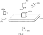
- FIG 2 schematically illustrates an FDM printer arrangement that comprises an FDM printer, such as the printer 100 of Figures 1A and 1B , which is being used to manufacture the object 200.
- an FDM printer such as the printer 100 of Figures 1A and 1B
- the working surface (also referred to as a substrate, in this disclosure) 230 is a heated substrate made of glass (for example) that is transparent or translucent to at least the particular frequency of infra-red (IR) light that is emitted by the IR light source 210.
- This light source is typically formed as an LED, but may be implemented as a bulb, laser or any other appropriate source.
- This arrangement also comprises a plurality of cameras 220a, 220b and 220c that are sensitive to IR light.
- the cameras 220a and 220b are arranged so as to be able to capture a substantially unobstructed view of the object 200, whilst the camera 220c is arranged so as to have the substrate 230 in the path of its view of the object 200.
- the cameras 220a and 220b are able to image the object 200 as it is being manufactured, as IR radiation is emitted as the heated plastic is added to the object as part of the manufacturing process. Images of the object 200 during the manufacturing process may be compared to models describing the manufacturing process in order to check that no substantial errors have been made. Such a monitoring and comparison method will be discussed in more detail below.
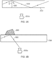
- Figure 3A schematically illustrates a portion of the substrate 230 with a light ray 300 being transmitted through the substrate, with arrows on the light ray 300 indicating a direction of travel.
- the dashed line 320 indicates the normal to the substrate-air interface as it extends into the substrate.
- the light ray 300 is emitted by the IR light source 210 of Figure 2 .
- the choice of material from which the substrate 230 is formed (in conjunction with the properties of a surrounding material, for example the air around the substrate 230) defines a critical angle of incidence above which total internal reflection occurs; the angle of incidence here refers to the angle at which the light ray 300 strikes the boundary of the substrate 230 (wherein the boundary of the substrate 230 defines the interface between two media, for example a substrate/air interface).
- total internal reflection therefore means that the light ray 300 is unable to be transmitted from the substrate 230 into the surrounding air.
- the light ray 300 is therefore effectively 'trapped', and as a result will not be detectable by the camera 220c.
- Figure 3B schematically illustrates a corresponding scenario in which the first (i.e. bottom) layer of the object 200 has been properly adhered to the substrate.
- a substrate/model interface is created, replacing the substrate/air interface that was previously present at the location of the object 200.
- This causes the critical angle and the angle of reflection to vary in accordance with the above equations, and total internal reflection may be prevented.
- One method by which this may occur is described as 'frustrated total internal reflection', in which if the object 200 is close enough to the substrate 230 (a distance of the order of the wavelength of the light ray) transmission of energy of the light ray 300 across the boundary occurs.
- the light ray 300 (or some component of the light ray 300) to interact with the object 200 which will have a reflective index that is different to that of the surrounding air. This will cause the light ray 300 to be reflected at a different angle to that at the interface where the object 200 is not present. As the object 200 will generally have a higher reflective index than the surrounding air, the new reflected angle will be smaller and therefore may no longer satisfy the angular requirement for total internal reflection to occur in the substrate 230. This may therefore allow the light ray 300 to be detected by the camera 220c, as the light ray 300 will no longer meet the angular condition for total internal reflection to occur and thus the light ray 300 may escape from the substrate 230 as is schematically illustrated in Figure 3B .
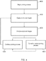
- Figure 4 schematically illustrates a method for performing a 3D printing process in which images of the model being printed is checked for faults throughout the printing process.
- the method starts at a step 400 in which the printing process is started.
- This step may include, or be preceded by, determining a 3D model that is to be printed and setting any operating parameters of the 3D printing arrangement such as temperature and pressure of the build chamber.
- the step 400 can comprise printing a portion of a 3D object using a 3D printer.
- IR images of the object being printed are captured by the array of IR cameras 220a, 220b and 220c as described above.
- the object 200 emits IR radiation as a result of heated plastic being used to print the object.
- the difference in temperature between the most-recently printed part of the object and previously printed parts of the object may make tracking the progress of the printing easier as the newly-added material may be easily identified in the captured images by its heat signature.
- the position of the object being printed can be determined in three dimensions.
- these captured images are analysed to detect the state of the 3D object, for example to identify errors in the printing process and/or to identify completion of the printing process.
- This analysis may take any appropriate form, for example the shape of the object being printed could be compared to a model of the design being printed.
- the model for comparison may be a complete model of the object being printed, alternatively (or in addition) one or more partial models corresponding to different levels of partial completion of the 3D printing process could be provided to act as a series of checkpoints against which the printing results can be compared.
- a real-time process could be performed in which the control software compares the instructions it provides to the 3D printing arrangement with images captured of the model being printed. As described above, it is possible to identify recently printed areas in an image and information about these areas may be compared with the printing instructions for the 3D printing process to determine whether or not the printing is sufficiently accurate to meet predetermined threshold standards.
- the method proceeds to a step 430 in which the printing process is continued, or alternatively ended if there is no more printing to be performed. If the printing is continued, the method returns to the step 410 in which further IR images of the object being printed are captured.
- Examples of unacceptable printing errors include the 3D object not having the expected shape at the current stage of printing, or the 3D object not being correctly adhered to the substrate upon which it is being printed.
- the tolerance of the 3D printing arrangement to such errors may be selected in dependence upon the intended use of the 3D object itself, for example a toy could have a larger tolerance for error than a 3D object that is intended to be used for scientific experiments, or any other appropriate factor.
- the tolerance for error could also vary in dependence upon the location of the error; a small error on the top of the 3D object that is only cosmetic may be more acceptable than a similar error on the base of the 3D object which causes structural problems or further mistakes to be made due to a dependence on the lower parts of the 3D object to be correctly printed so that layers may be added on top correctly, for example.
- the printing process may be restarted at the step 440. This comprises removing the partially printed object from the printer and starting the printing process from the step 400. Alternatively, if the error is correctable then adjustments could be made to the printing process before proceeding to the step 430 and continuing printing the object.
- This list of operational parameters is not exhaustive, and the variation of the operating parameters of the 3D printer may also or otherwise include the adjustment of any other appropriate operating parameters.
- an alarm may be used to signal a human operator to intervene and make an independent assessment and/or adjustment of the operating parameters in addition to taking any other appropriate actions with regards to the 3D printing process.
- the selection of which of the above adjustments to make may be determined based upon the results of the analysis of the captured images. For example, if a greater-than-expected amount of IR radiation is captured from the base of the object and/or the shape at the bottom of the object is disfigured then it would be apparent that the substrate is too hot and the temperature should be lowered. Appropriate adjustments may correspond to any detected image features in this manner, and it may also be the case that a detected problem may be corrected by implementing any of more than one of the adjustments listed above; for example increasing the level of active cooling applied to the printed object may have a comparable effect to decreasing the temperature of the build chamber.
- Applying the adjustments may be an iterative process in which adjustments may be implemented successively. This may be to establish the magnitude of the adjustment that should be applied, for example such that several adjustments of a 1°C are made that converge on a suitable temperature rather immediately being able to calculate the exact change in temperature required. Alternatively, this may be because a variation of the operating parameters of the 3D printer is an adjustment of a complex system and as a result other operating parameters may need to be varied in order to achieve a suitable correction to the 3D printing process. For example lowering the temperature of the substrate may solve the problem of the base of the 3D object being too hot, but this may lead to a cooling of the build chamber which in turn could cause other problems in the printing process and therefore other operating parameters would need to be adjusted separately to account for this.
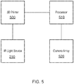
- FIG. 5 schematically illustrates a 3D printing system.
- This system comprises a 3D printer 500, a processor 510, and a camera array 520.
- an IR light source 210 is also provided.
- the 3D printer 500 may be the same as the 3D printer 100 illustrated in Figures 1A and 1B . However it may also have various features not found in the arrangement described with reference to Figures 1A and 1B , such as the substrate 230 that is described with reference to Figure 2 .
- the 3D printer 500 is an example of a 3D printing arrangement that is operable to print a 3D object.
- the optional IR light source 210 is arranged so as to interact with the 3D printer 500 as described above with reference to Figure 2 .
- the IR light source 210 is provided, it is arranged to illuminate the substrate 230 of the 3D printer 500 in such a manner so as to cause total internal reflection of the infra-red light to occur in the substrate 230 when a 3D object is not adhered to the substrate 230.
- a camera of the camera array 520 is arranged to view the surface of the substrate 230 opposite to that which the 3D object is printed upon.
- the processor 510 is operable to analyse images of the 3D object captured by the array of infra-red cameras to detect the state of the object being printed.
- the processor 510 is operable to control (and receive data from) the camera array 520 and perform an analysis of the images captured by the camera array 520.
- This analysis of images of the 3D object captured by the camera array 520 may comprise the identification of errors in the 3D printing process by the processor 510.
- the analysis of images of the 3D object captured by the camera array 520 is used to identify completion of the 3D printing process.
- the processor 510 may then provide instructions to the 3D printer in response to the results of this analysis.
- the analysis performed by the processor 510 is discussed above with reference to Figure 4 .
- the analysis may comprise comparing captured images to a model of the 3D object, or a model of a portion of the 3D object. Alternatively, or in addition, the comparison may be made with respect to a model of a partially-completed 3D object.
- the analysis of the captured images comprises comparing captured images to printing instructions for printing the 3D object; this may be performed instead of or in conjunction with the comparison to a model of the 3D object.
- the camera array 520 comprises one or more IR cameras such as those 220a, 220b and 220c in Figure 2 .
- the camera array 520 is operable to capture images of the 3D object being printed by the 3D printer 500, and provides these images to the processor 510 for analysis.
- the cameras in the camera array 520 may each capture stereoscopic images in embodiments of the present disclosure.
Landscapes
- Engineering & Computer Science (AREA)
- Chemical & Material Sciences (AREA)
- Materials Engineering (AREA)
- Manufacturing & Machinery (AREA)
- Physics & Mathematics (AREA)
- Mechanical Engineering (AREA)
- Optics & Photonics (AREA)
- Computer Vision & Pattern Recognition (AREA)
- General Physics & Mathematics (AREA)
- Theoretical Computer Science (AREA)
Claims (15)
- 3D-Druck-System, wobei das System Folgendes umfasst:eine 3D-Druck-Anordnung (500), betriebsfähig zum Drucken eines 3D-Objekts;eine Verarbeitungseinheit (510), betriebsfähig zum Analysieren von durch eine Infrarotkamera (520) erfassten Bildern, um den Zustand des Objekts, das gedruckt wird, zu detektieren;ein Substrat (230), auf dem das 3D-gedruckte Objekt während des 3D-Druck-Prozesses angehaftet wird; undgekennzeichnet durcheine Infrarotlichtquelle (210), eingerichtet zum derartigen Beleuchten des Substrats, dass ein Auftreten einer internen Totalreflexion des Infrarotlichts in dem Substrat bewirkt wird, wenn das 3D-Objekt nicht an dem Substrat haftet, wobei das Substrat transparent oder transluzent gegenüber zumindest einer bestimmten Frequenz von Infrarotlicht, das durch die Infrarotlichtquelle emittiert wird, ist;wobei die Infrarotkamera dahingehend angeordnet ist, die Oberfläche des Substrats gegenüber jener, auf der das 3D-Objekt gedruckt wird, zu betrachten, sodass die Kamera Bilder des 3D-Objekts erfassen kann, wenn es korrekt an dem Substrat haftet; unddie Verarbeitungseinheit betriebsfähig ist zum Analysieren der erfassten Bilder, um zu detektieren, ob das 3D-Objekt korrekt an dem Substrat haftet.
- 3D-Druck-System nach Anspruch 1, umfassend ein Array von Infrarotkameras, betriebsfähig zum Erfassen von Bildern des 3D-Objekts, das durch die 3D-Druck-Anordnung gedruckt wird.
- 3D-Druck-System nach Anspruch 2, wobei die Verarbeitungseinheit ausgelegt ist zum Verwenden der Analyse der durch das Array von Infrarotkameras erfassten Bilder des 3D-Objekts, um Fehler in dem 3D-Druck-Prozess zu identifizieren.
- 3D-Druck-System nach Anspruch 2, wobei die Verarbeitungseinheit ausgelegt ist zum Verwenden der Analyse von durch das Array von Infrarotkameras erfassten Bildern des 3D-Objekts, um eine Fertigstellung des 3D-Druck-Prozesses zu identifizieren.
- 3D-Druck-System nach Anspruch 2, wobei die Infrarotkameras zum Erfassen stereoskopischer Bilder ausgelegt sind.
- 3D-Druck-System nach Anspruch 2, wobei die Analyse der erfassten Bilder einen Vergleich erfasster Bilder mit einem Modell des 3D-Objekts umfasst.
- 3D-Druck-System nach Anspruch 6, wobei das Modell des 3D-Objekts ein Modell eines teilweise fertiggestellten 3D-Objekts ist.
- 3D-Druck-System nach Anspruch 6, wobei die Analyse der erfassten Bilder Vergleichen erfasster Bilder mit Druckanweisungen zum Drucken des 3D-Objekts umfasst.
- 3D-Druck-System nach Anspruch 1, wobei, wenn ein Fehler in dem 3D-Druck-Prozess identifiziert wird, der 3D-Druck-Prozess erneut gestartet wird.
- 3D-Druck-System nach Anspruch 2, wobei Betriebsparameter der 3D-Druck-Anordnung als Reaktion auf die Analyse der erfassten Bilder angepasst werden.
- 3D-Druck-Verfahren zur Verwendung mit einem 3D-Druck-System, wobei das Verfahren Folgendes umfasst:Drucken eines Abschnitts eines 3D-Objekts unter Verwendung eines 3D-Druckers; undBereitstellen eines Substrats, auf dem das 3D-gedruckte Objekt während des 3D-Druck-Prozesses angehaftet wird;gekennzeichnet durchAnordnen einer Infrarotlichtquelle zum derartigen Beleuchten des Substrats, dass ein Auftreten einer internen Totalreflexion des Infrarotlichts in dem Substrat bewirkt wird, wenn das 3D-Objekt nicht an dem Substrat haftet, wobei das Substrat transparent oder transluzent gegenüber zumindest einer bestimmten Frequenz von Infrarotlicht, das durch die Infrarotlichtquelle emittiert wird, ist;Betrachten der Oberfläche des Substrats gegenüber jener, auf der das 3D-Objekt gedruckt wird, mit einer Infrarotkamera, sodass die Kamera Bilder des 3D-Objekts erfassen kann, wenn es korrekt an dem Substrat haftet; undAnalysieren der erfassten Bilder, um zu detektieren, ob das 3D-Objekt korrekt an dem Substrat haftet.
- 3D-Druck-Verfahren nach Anspruch 11, umfassend die Folgenden Schritte:Erfassen von Bildern des 3D-Objekts, das gedruckt wird, unter Verwendung eines Arrays von Infrarotkameras; undAnalysieren der erfassten Bilder des 3D-Objekts, um den Zustand des 3D-Objekts zu detektieren.
- 3D-Druck-Verfahren nach Anspruch 12, umfassend Anpassen von Betriebsparametern des 3D-Druckers als Reaktion auf die Analyse der erfassten Bilder.
- Computersoftware, umfassend Anweisungen zum Bewirken, dass die Vorrichtung nach einem der Ansprüche 1 bis 10 das Verfahren nach einem der Ansprüche 11 bis 13 ausführt.
- Maschinenlesbares nichtflüchtiges Speichermedium, das Computersoftware nach Anspruch 14 speichert.
Applications Claiming Priority (2)
| Application Number | Priority Date | Filing Date | Title |
|---|---|---|---|
| GB1604950.4A GB2549071B (en) | 2016-03-23 | 2016-03-23 | 3D printing system |
| PCT/GB2017/050402 WO2017163000A1 (en) | 2016-03-23 | 2017-02-16 | 3d printing system |
Publications (2)
| Publication Number | Publication Date |
|---|---|
| EP3433085A1 EP3433085A1 (de) | 2019-01-30 |
| EP3433085B1 true EP3433085B1 (de) | 2021-06-30 |
Family
ID=55968780
Family Applications (1)
| Application Number | Title | Priority Date | Filing Date |
|---|---|---|---|
| EP17706863.2A Active EP3433085B1 (de) | 2016-03-23 | 2017-02-16 | 3d-drucksystem |
Country Status (6)
| Country | Link |
|---|---|
| US (1) | US11420394B2 (de) |
| EP (1) | EP3433085B1 (de) |
| JP (1) | JP6846433B2 (de) |
| CN (1) | CN108778687B (de) |
| GB (1) | GB2549071B (de) |
| WO (1) | WO2017163000A1 (de) |
Families Citing this family (20)
| Publication number | Priority date | Publication date | Assignee | Title |
|---|---|---|---|---|
| WO2018200383A1 (en) * | 2017-04-24 | 2018-11-01 | Desktop Metal, Inc. | Three-dimensional (3d) printing using measured processing effects with feedback to processing parameters |
| EP3697592A4 (de) * | 2017-10-16 | 2021-05-19 | Hewlett-Packard Development Company, L.P. | 3d-drucker |
| CN108000874B (zh) * | 2017-12-07 | 2019-11-29 | 徐素香 | 一种3d打印机 |
| CN107775953B (zh) * | 2017-12-07 | 2020-01-07 | 徐素香 | 一种自动中断3d打印机继续供料的方法 |
| EP3765255B1 (de) * | 2018-03-10 | 2025-07-30 | PostProcess Technologies Inc. | System und verfahren zur herstellung eines additiv gefertigten objekts |
| US11084225B2 (en) | 2018-04-02 | 2021-08-10 | Nanotronics Imaging, Inc. | Systems, methods, and media for artificial intelligence process control in additive manufacturing |
| CN109703033A (zh) * | 2019-01-18 | 2019-05-03 | 深圳市硬核智娱科技有限公司 | 一种具有对比功能的稳定连接式积木3d打印系统 |
| US11104077B2 (en) * | 2019-03-29 | 2021-08-31 | Xerox Corporation | Composite-based additive manufacturing (CBAM) image quality (IQ) verification and rejection handling |
| EP3921711B1 (de) * | 2019-04-19 | 2024-02-14 | Nanotronics Imaging, Inc. | Systeme, verfahren und medien zur steuerung eines prozesses der künstlichen intelligenz in der generativen fertigung |
| DE102019121658A1 (de) * | 2019-08-12 | 2021-02-18 | Röchling Automotive SE & Co. KG | Vorrichtung mit einer Klimakammeranordnung zum Ausführen eines Schmelzschichtungsverfahrens |
| CN110625944A (zh) * | 2019-09-18 | 2019-12-31 | 南京航空航天大学 | 一种风力发电机叶片模具的3d打印方法 |
| WO2021086319A1 (en) * | 2019-10-29 | 2021-05-06 | Hewlett-Packard Development Company, L.P. | Generation of model data for three dimensional printers |
| CN115087538B (zh) * | 2020-01-23 | 2023-04-11 | 因帕瑟伯物体公司 | 用于3d打印的基于摄像机的监控系统 |
| US12070861B2 (en) * | 2020-04-14 | 2024-08-27 | 3Deo, Inc. | Robotics for three-dimensional printing |
| US11518109B2 (en) * | 2020-10-30 | 2022-12-06 | Inkbit, LLC | Thermal management for additive fabrication |
| US12441053B1 (en) * | 2021-03-19 | 2025-10-14 | Florida A&M University | System and method of optimizing adhesion dynamics during deposition of thermoplastic materials |
| JP7347715B1 (ja) * | 2021-11-04 | 2023-09-20 | 株式会社プロテリアル | 積層造形体の寸法品質評価方法及びその評価システム |
| JP2024073775A (ja) * | 2022-11-18 | 2024-05-30 | セイコーエプソン株式会社 | 三次元造形システム |
| KR102849197B1 (ko) * | 2023-01-17 | 2025-08-21 | 두산에너빌리티 주식회사 | 금속 3d 프린터 |
| DE102023206928B4 (de) * | 2023-07-20 | 2025-02-20 | Friedrich-Alexander-Universität Erlangen-Nürnberg, Körperschaft des öffentlichen Rechts | 3D-Druckgerät |
Family Cites Families (22)
| Publication number | Priority date | Publication date | Assignee | Title |
|---|---|---|---|---|
| JPH08166219A (ja) * | 1994-12-12 | 1996-06-25 | Minolta Co Ltd | 形状計測機 |
| JPH08166523A (ja) * | 1994-12-13 | 1996-06-25 | Hitachi Ltd | 光アセンブリ |
| US20040058407A1 (en) * | 2001-04-10 | 2004-03-25 | Miller Scott E. | Reactor systems having a light-interacting component |
| JP2004537721A (ja) * | 2001-07-30 | 2004-12-16 | 日本板硝子株式会社 | 光学式液滴検出装置およびそれを用いた制御装置 |
| CA2504368C (en) * | 2002-10-31 | 2012-07-10 | Ehsan Toyserkani | System and method for closed-loop control of laser cladding by powder injection |
| US7964439B2 (en) * | 2002-12-20 | 2011-06-21 | The Trustees Of Princeton University | Methods of fabricating devices by transfer of organic material |
| US20040156539A1 (en) * | 2003-02-10 | 2004-08-12 | Asm Assembly Automation Ltd | Inspecting an array of electronic components |
| US8077305B2 (en) * | 2004-04-19 | 2011-12-13 | Owen Mark D | Imaging semiconductor structures using solid state illumination |
| US7939003B2 (en) * | 2004-08-11 | 2011-05-10 | Cornell Research Foundation, Inc. | Modular fabrication systems and methods |
| JP2008215976A (ja) * | 2007-03-02 | 2008-09-18 | Nikon Corp | 基板検査装置 |
| US8581852B2 (en) * | 2007-11-15 | 2013-11-12 | Microsoft Corporation | Fingertip detection for camera based multi-touch systems |
| DE102007056984A1 (de) | 2007-11-27 | 2009-05-28 | Eos Gmbh Electro Optical Systems | Verfahren zum Herstellen eines dreidimensionalen Objekts mittels Lasersintern |
| US9481134B2 (en) * | 2012-06-08 | 2016-11-01 | Makerbot Industries, Llc | Build platform leveling with tactile feedback |
| US20140120196A1 (en) | 2012-10-29 | 2014-05-01 | Makerbot Industries, Llc | Quick-release extruder |
| US9470911B2 (en) * | 2013-08-22 | 2016-10-18 | Bespoke, Inc. | Method and system to create products |
| US9952448B2 (en) * | 2014-03-26 | 2018-04-24 | Indizen Optical Technologies, S.L. | Eyewear lens production by additive techniques |
| US9079440B1 (en) | 2014-03-31 | 2015-07-14 | Xerox Corporation | System for detecting inoperative inkjets in printheads ejecting clear ink using a light transmitting substrate |
| TWI518583B (zh) * | 2014-04-18 | 2016-01-21 | 三緯國際立體列印科技股份有限公司 | 立體列印裝置及其列印異常偵測方法 |
| US20150306823A1 (en) * | 2014-04-29 | 2015-10-29 | Makerbot Industries, Llc | Multiple extrusion in three-dimensional printing |
| WO2016040453A1 (en) * | 2014-09-10 | 2016-03-17 | The Exone Company | Three-dimensional printing progress verification methods and apparatuses |
| US20160098824A1 (en) * | 2014-10-03 | 2016-04-07 | Tyco Electronics Corporation | Three dimensional printing inspection apparatus and method |
| WO2016118782A1 (en) * | 2015-01-21 | 2016-07-28 | University Of North Dakota | Characterizing 3-d printed objects for 3-d printing |
-
2016
- 2016-03-23 GB GB1604950.4A patent/GB2549071B/en active Active
-
2017
- 2017-02-16 WO PCT/GB2017/050402 patent/WO2017163000A1/en not_active Ceased
- 2017-02-16 US US16/086,199 patent/US11420394B2/en active Active
- 2017-02-16 JP JP2018550360A patent/JP6846433B2/ja active Active
- 2017-02-16 CN CN201780019525.1A patent/CN108778687B/zh active Active
- 2017-02-16 EP EP17706863.2A patent/EP3433085B1/de active Active
Also Published As
| Publication number | Publication date |
|---|---|
| US11420394B2 (en) | 2022-08-23 |
| US20190358907A1 (en) | 2019-11-28 |
| WO2017163000A1 (en) | 2017-09-28 |
| CN108778687B (zh) | 2021-08-17 |
| JP6846433B2 (ja) | 2021-03-24 |
| EP3433085A1 (de) | 2019-01-30 |
| GB2549071B (en) | 2020-11-11 |
| GB201604950D0 (en) | 2016-05-04 |
| GB2549071A (en) | 2017-10-11 |
| JP2019509917A (ja) | 2019-04-11 |
| CN108778687A (zh) | 2018-11-09 |
Similar Documents
| Publication | Publication Date | Title |
|---|---|---|
| US11420394B2 (en) | 3D printing system | |
| US9912915B2 (en) | Verification and adjustment systems and methods for additive manufacturing | |
| US10556381B2 (en) | Three-dimensional printer with force detection | |
| TWI518583B (zh) | 立體列印裝置及其列印異常偵測方法 | |
| US10753955B2 (en) | Systems and method for advanced additive manufacturing | |
| US11027535B2 (en) | Systems and method for advanced additive manufacturing | |
| US20160129633A1 (en) | Three dimensional printing apparatus and three dimensional printing method | |
| CN111107973A (zh) | 3d打印机 | |
| KR20180124125A (ko) | 층간 열적 기여 | |
| JP7341925B2 (ja) | 複合体系積層造形(cbam)画像品質(iq)の検証及び拒絶処理 | |
| US9718239B2 (en) | Three dimensional printing apparatus and three dimensional printing method | |
| Mehta et al. | Editors’ choice—review—sensor-based and computational methods for error detection and correction in 3D printing | |
| CN113118456A (zh) | 用于估算3d打印过程中形成的3d打印物体高度的方法和装置,及3d打印系统 | |
| KR20150098340A (ko) | 오토레벨러 및 모재 냉각부가 구비되는 노즐유닛 | |
| US12629894B2 (en) | Apparatus and method for performing in-process testing for verification of print parameters in a 3D printing apparatus | |
| EP3250365A1 (de) | Drucktotbereichsidentifizierung | |
| SE537864C2 (sv) | En metod och en apparat för geometrisk verifiering vid additiv tillverkning av tredimensionella objekt | |
| CN116394521B (zh) | 一种用于3d打印喷头三坐标自动定位装置及定位成型方法 | |
| HK1260640A1 (en) | 3d printing system | |
| HK1260640B (en) | 3d printing system | |
| US20210252785A1 (en) | Calibrating cameras in three-dimensional printer devices | |
| US20200307097A1 (en) | Composite-based additive manufacturing (cbam) augmented reality assisted sand blasting | |
| EP3233426B1 (de) | Erkennung von anomalien bei einem dreidimensionalen drucker | |
| EP3383610B1 (de) | Überwachung der bereitstellung von baumaterial in systemen zur generativen fertigung | |
| WO2025133018A1 (en) | Material jetting |
Legal Events
| Date | Code | Title | Description |
|---|---|---|---|
| STAA | Information on the status of an ep patent application or granted ep patent |
Free format text: STATUS: UNKNOWN |
|
| STAA | Information on the status of an ep patent application or granted ep patent |
Free format text: STATUS: THE INTERNATIONAL PUBLICATION HAS BEEN MADE |
|
| PUAI | Public reference made under article 153(3) epc to a published international application that has entered the european phase |
Free format text: ORIGINAL CODE: 0009012 |
|
| STAA | Information on the status of an ep patent application or granted ep patent |
Free format text: STATUS: REQUEST FOR EXAMINATION WAS MADE |
|
| 17P | Request for examination filed |
Effective date: 20180924 |
|
| AK | Designated contracting states |
Kind code of ref document: A1 Designated state(s): AL AT BE BG CH CY CZ DE DK EE ES FI FR GB GR HR HU IE IS IT LI LT LU LV MC MK MT NL NO PL PT RO RS SE SI SK SM TR |
|
| AX | Request for extension of the european patent |
Extension state: BA ME |
|
| DAV | Request for validation of the european patent (deleted) | ||
| DAX | Request for extension of the european patent (deleted) | ||
| REG | Reference to a national code |
Ref country code: DE Ref legal event code: R079 Ref document number: 602017041167 Country of ref document: DE Free format text: PREVIOUS MAIN CLASS: B29C0067000000 Ipc: B29C0064393000 |
|
| RIC1 | Information provided on ipc code assigned before grant |
Ipc: B29C 64/106 20170101ALI20201203BHEP Ipc: B29C 64/393 20170101AFI20201203BHEP Ipc: B33Y 50/02 20150101ALI20201203BHEP Ipc: B33Y 30/00 20150101ALI20201203BHEP Ipc: G06F 3/042 20060101ALI20201203BHEP |
|
| GRAP | Despatch of communication of intention to grant a patent |
Free format text: ORIGINAL CODE: EPIDOSNIGR1 |
|
| STAA | Information on the status of an ep patent application or granted ep patent |
Free format text: STATUS: GRANT OF PATENT IS INTENDED |
|
| INTG | Intention to grant announced |
Effective date: 20210204 |
|
| GRAS | Grant fee paid |
Free format text: ORIGINAL CODE: EPIDOSNIGR3 |
|
| GRAA | (expected) grant |
Free format text: ORIGINAL CODE: 0009210 |
|
| STAA | Information on the status of an ep patent application or granted ep patent |
Free format text: STATUS: THE PATENT HAS BEEN GRANTED |
|
| AK | Designated contracting states |
Kind code of ref document: B1 Designated state(s): AL AT BE BG CH CY CZ DE DK EE ES FI FR GB GR HR HU IE IS IT LI LT LU LV MC MK MT NL NO PL PT RO RS SE SI SK SM TR |
|
| REG | Reference to a national code |
Ref country code: CH Ref legal event code: EP |
|
| REG | Reference to a national code |
Ref country code: AT Ref legal event code: REF Ref document number: 1405959 Country of ref document: AT Kind code of ref document: T Effective date: 20210715 |
|
| REG | Reference to a national code |
Ref country code: NL Ref legal event code: FP |
|
| REG | Reference to a national code |
Ref country code: DE Ref legal event code: R096 Ref document number: 602017041167 Country of ref document: DE |
|
| REG | Reference to a national code |
Ref country code: IE Ref legal event code: FG4D |
|
| REG | Reference to a national code |
Ref country code: LT Ref legal event code: MG9D |
|
| PG25 | Lapsed in a contracting state [announced via postgrant information from national office to epo] |
Ref country code: FI Free format text: LAPSE BECAUSE OF FAILURE TO SUBMIT A TRANSLATION OF THE DESCRIPTION OR TO PAY THE FEE WITHIN THE PRESCRIBED TIME-LIMIT Effective date: 20210630 Ref country code: BG Free format text: LAPSE BECAUSE OF FAILURE TO SUBMIT A TRANSLATION OF THE DESCRIPTION OR TO PAY THE FEE WITHIN THE PRESCRIBED TIME-LIMIT Effective date: 20210930 Ref country code: HR Free format text: LAPSE BECAUSE OF FAILURE TO SUBMIT A TRANSLATION OF THE DESCRIPTION OR TO PAY THE FEE WITHIN THE PRESCRIBED TIME-LIMIT Effective date: 20210630 |
|
| REG | Reference to a national code |
Ref country code: AT Ref legal event code: MK05 Ref document number: 1405959 Country of ref document: AT Kind code of ref document: T Effective date: 20210630 |
|
| PG25 | Lapsed in a contracting state [announced via postgrant information from national office to epo] |
Ref country code: LV Free format text: LAPSE BECAUSE OF FAILURE TO SUBMIT A TRANSLATION OF THE DESCRIPTION OR TO PAY THE FEE WITHIN THE PRESCRIBED TIME-LIMIT Effective date: 20210630 Ref country code: GR Free format text: LAPSE BECAUSE OF FAILURE TO SUBMIT A TRANSLATION OF THE DESCRIPTION OR TO PAY THE FEE WITHIN THE PRESCRIBED TIME-LIMIT Effective date: 20211001 Ref country code: SE Free format text: LAPSE BECAUSE OF FAILURE TO SUBMIT A TRANSLATION OF THE DESCRIPTION OR TO PAY THE FEE WITHIN THE PRESCRIBED TIME-LIMIT Effective date: 20210630 Ref country code: RS Free format text: LAPSE BECAUSE OF FAILURE TO SUBMIT A TRANSLATION OF THE DESCRIPTION OR TO PAY THE FEE WITHIN THE PRESCRIBED TIME-LIMIT Effective date: 20210630 Ref country code: NO Free format text: LAPSE BECAUSE OF FAILURE TO SUBMIT A TRANSLATION OF THE DESCRIPTION OR TO PAY THE FEE WITHIN THE PRESCRIBED TIME-LIMIT Effective date: 20210930 |
|
| PG25 | Lapsed in a contracting state [announced via postgrant information from national office to epo] |
Ref country code: EE Free format text: LAPSE BECAUSE OF FAILURE TO SUBMIT A TRANSLATION OF THE DESCRIPTION OR TO PAY THE FEE WITHIN THE PRESCRIBED TIME-LIMIT Effective date: 20210630 Ref country code: CZ Free format text: LAPSE BECAUSE OF FAILURE TO SUBMIT A TRANSLATION OF THE DESCRIPTION OR TO PAY THE FEE WITHIN THE PRESCRIBED TIME-LIMIT Effective date: 20210630 Ref country code: AT Free format text: LAPSE BECAUSE OF FAILURE TO SUBMIT A TRANSLATION OF THE DESCRIPTION OR TO PAY THE FEE WITHIN THE PRESCRIBED TIME-LIMIT Effective date: 20210630 Ref country code: PT Free format text: LAPSE BECAUSE OF FAILURE TO SUBMIT A TRANSLATION OF THE DESCRIPTION OR TO PAY THE FEE WITHIN THE PRESCRIBED TIME-LIMIT Effective date: 20211102 Ref country code: RO Free format text: LAPSE BECAUSE OF FAILURE TO SUBMIT A TRANSLATION OF THE DESCRIPTION OR TO PAY THE FEE WITHIN THE PRESCRIBED TIME-LIMIT Effective date: 20210630 Ref country code: ES Free format text: LAPSE BECAUSE OF FAILURE TO SUBMIT A TRANSLATION OF THE DESCRIPTION OR TO PAY THE FEE WITHIN THE PRESCRIBED TIME-LIMIT Effective date: 20210630 Ref country code: SM Free format text: LAPSE BECAUSE OF FAILURE TO SUBMIT A TRANSLATION OF THE DESCRIPTION OR TO PAY THE FEE WITHIN THE PRESCRIBED TIME-LIMIT Effective date: 20210630 Ref country code: SK Free format text: LAPSE BECAUSE OF FAILURE TO SUBMIT A TRANSLATION OF THE DESCRIPTION OR TO PAY THE FEE WITHIN THE PRESCRIBED TIME-LIMIT Effective date: 20210630 |
|
| PG25 | Lapsed in a contracting state [announced via postgrant information from national office to epo] |
Ref country code: PL Free format text: LAPSE BECAUSE OF FAILURE TO SUBMIT A TRANSLATION OF THE DESCRIPTION OR TO PAY THE FEE WITHIN THE PRESCRIBED TIME-LIMIT Effective date: 20210630 |
|
| REG | Reference to a national code |
Ref country code: DE Ref legal event code: R097 Ref document number: 602017041167 Country of ref document: DE |
|
| PG25 | Lapsed in a contracting state [announced via postgrant information from national office to epo] |
Ref country code: DK Free format text: LAPSE BECAUSE OF FAILURE TO SUBMIT A TRANSLATION OF THE DESCRIPTION OR TO PAY THE FEE WITHIN THE PRESCRIBED TIME-LIMIT Effective date: 20210630 |
|
| PLBE | No opposition filed within time limit |
Free format text: ORIGINAL CODE: 0009261 |
|
| STAA | Information on the status of an ep patent application or granted ep patent |
Free format text: STATUS: NO OPPOSITION FILED WITHIN TIME LIMIT |
|
| PG25 | Lapsed in a contracting state [announced via postgrant information from national office to epo] |
Ref country code: AL Free format text: LAPSE BECAUSE OF FAILURE TO SUBMIT A TRANSLATION OF THE DESCRIPTION OR TO PAY THE FEE WITHIN THE PRESCRIBED TIME-LIMIT Effective date: 20210630 |
|
| 26N | No opposition filed |
Effective date: 20220331 |
|
| PG25 | Lapsed in a contracting state [announced via postgrant information from national office to epo] |
Ref country code: IT Free format text: LAPSE BECAUSE OF FAILURE TO SUBMIT A TRANSLATION OF THE DESCRIPTION OR TO PAY THE FEE WITHIN THE PRESCRIBED TIME-LIMIT Effective date: 20210630 |
|
| PG25 | Lapsed in a contracting state [announced via postgrant information from national office to epo] |
Ref country code: MC Free format text: LAPSE BECAUSE OF FAILURE TO SUBMIT A TRANSLATION OF THE DESCRIPTION OR TO PAY THE FEE WITHIN THE PRESCRIBED TIME-LIMIT Effective date: 20210630 |
|
| REG | Reference to a national code |
Ref country code: CH Ref legal event code: PL |
|
| REG | Reference to a national code |
Ref country code: BE Ref legal event code: MM Effective date: 20220228 |
|
| PG25 | Lapsed in a contracting state [announced via postgrant information from national office to epo] |
Ref country code: LU Free format text: LAPSE BECAUSE OF NON-PAYMENT OF DUE FEES Effective date: 20220216 |
|
| PG25 | Lapsed in a contracting state [announced via postgrant information from national office to epo] |
Ref country code: LI Free format text: LAPSE BECAUSE OF NON-PAYMENT OF DUE FEES Effective date: 20220228 Ref country code: IE Free format text: LAPSE BECAUSE OF NON-PAYMENT OF DUE FEES Effective date: 20220216 Ref country code: CH Free format text: LAPSE BECAUSE OF NON-PAYMENT OF DUE FEES Effective date: 20220228 |
|
| PG25 | Lapsed in a contracting state [announced via postgrant information from national office to epo] |
Ref country code: BE Free format text: LAPSE BECAUSE OF NON-PAYMENT OF DUE FEES Effective date: 20220228 |
|
| PG25 | Lapsed in a contracting state [announced via postgrant information from national office to epo] |
Ref country code: LT Free format text: LAPSE BECAUSE OF FAILURE TO SUBMIT A TRANSLATION OF THE DESCRIPTION OR TO PAY THE FEE WITHIN THE PRESCRIBED TIME-LIMIT Effective date: 20210630 |
|
| P01 | Opt-out of the competence of the unified patent court (upc) registered |
Effective date: 20230519 |
|
| PG25 | Lapsed in a contracting state [announced via postgrant information from national office to epo] |
Ref country code: HU Free format text: LAPSE BECAUSE OF FAILURE TO SUBMIT A TRANSLATION OF THE DESCRIPTION OR TO PAY THE FEE WITHIN THE PRESCRIBED TIME-LIMIT; INVALID AB INITIO Effective date: 20170216 |
|
| PG25 | Lapsed in a contracting state [announced via postgrant information from national office to epo] |
Ref country code: MK Free format text: LAPSE BECAUSE OF FAILURE TO SUBMIT A TRANSLATION OF THE DESCRIPTION OR TO PAY THE FEE WITHIN THE PRESCRIBED TIME-LIMIT Effective date: 20210630 Ref country code: CY Free format text: LAPSE BECAUSE OF FAILURE TO SUBMIT A TRANSLATION OF THE DESCRIPTION OR TO PAY THE FEE WITHIN THE PRESCRIBED TIME-LIMIT Effective date: 20210630 |
|
| PG25 | Lapsed in a contracting state [announced via postgrant information from national office to epo] |
Ref country code: MT Free format text: LAPSE BECAUSE OF FAILURE TO SUBMIT A TRANSLATION OF THE DESCRIPTION OR TO PAY THE FEE WITHIN THE PRESCRIBED TIME-LIMIT Effective date: 20210630 |
|
| PG25 | Lapsed in a contracting state [announced via postgrant information from national office to epo] |
Ref country code: TR Free format text: LAPSE BECAUSE OF FAILURE TO SUBMIT A TRANSLATION OF THE DESCRIPTION OR TO PAY THE FEE WITHIN THE PRESCRIBED TIME-LIMIT Effective date: 20210630 |
|
| PGFP | Annual fee paid to national office [announced via postgrant information from national office to epo] |
Ref country code: NL Payment date: 20260121 Year of fee payment: 10 |
|
| PGFP | Annual fee paid to national office [announced via postgrant information from national office to epo] |
Ref country code: GB Payment date: 20260121 Year of fee payment: 10 |
|
| PGFP | Annual fee paid to national office [announced via postgrant information from national office to epo] |
Ref country code: DE Payment date: 20260121 Year of fee payment: 10 |
|
| PGFP | Annual fee paid to national office [announced via postgrant information from national office to epo] |
Ref country code: FR Payment date: 20260121 Year of fee payment: 10 |