EP3432450A1 - Formspule mit vorheriger bewicklung mit glimmerband - Google Patents
Formspule mit vorheriger bewicklung mit glimmerband Download PDFInfo
- Publication number
- EP3432450A1 EP3432450A1 EP17182597.9A EP17182597A EP3432450A1 EP 3432450 A1 EP3432450 A1 EP 3432450A1 EP 17182597 A EP17182597 A EP 17182597A EP 3432450 A1 EP3432450 A1 EP 3432450A1
- Authority
- EP
- European Patent Office
- Prior art keywords
- coil
- mica tape
- layers
- shroud
- stator
- Prior art date
- Legal status (The legal status is an assumption and is not a legal conclusion. Google has not performed a legal analysis and makes no representation as to the accuracy of the status listed.)
- Granted
Links
Images


Classifications
-
- H—ELECTRICITY
- H02—GENERATION; CONVERSION OR DISTRIBUTION OF ELECTRIC POWER
- H02K—DYNAMO-ELECTRIC MACHINES
- H02K3/00—Details of windings
- H02K3/32—Windings characterised by the shape, form or construction of the insulation
- H02K3/34—Windings characterised by the shape, form or construction of the insulation between conductors or between conductor and core, e.g. slot insulation
-
- B—PERFORMING OPERATIONS; TRANSPORTING
- B32—LAYERED PRODUCTS
- B32B—LAYERED PRODUCTS, i.e. PRODUCTS BUILT-UP OF STRATA OF FLAT OR NON-FLAT, e.g. CELLULAR OR HONEYCOMB, FORM
- B32B27/00—Layered products comprising a layer of synthetic resin
- B32B27/12—Layered products comprising a layer of synthetic resin next to a fibrous or filamentary layer
-
- B—PERFORMING OPERATIONS; TRANSPORTING
- B32—LAYERED PRODUCTS
- B32B—LAYERED PRODUCTS, i.e. PRODUCTS BUILT-UP OF STRATA OF FLAT OR NON-FLAT, e.g. CELLULAR OR HONEYCOMB, FORM
- B32B27/00—Layered products comprising a layer of synthetic resin
- B32B27/28—Layered products comprising a layer of synthetic resin comprising synthetic resins not wholly covered by any one of the sub-groups B32B27/30 - B32B27/42
- B32B27/281—Layered products comprising a layer of synthetic resin comprising synthetic resins not wholly covered by any one of the sub-groups B32B27/30 - B32B27/42 comprising polyimides
-
- B—PERFORMING OPERATIONS; TRANSPORTING
- B32—LAYERED PRODUCTS
- B32B—LAYERED PRODUCTS, i.e. PRODUCTS BUILT-UP OF STRATA OF FLAT OR NON-FLAT, e.g. CELLULAR OR HONEYCOMB, FORM
- B32B5/00—Layered products characterised by the non- homogeneity or physical structure, i.e. comprising a fibrous, filamentary, particulate or foam layer; Layered products characterised by having a layer differing constitutionally or physically in different parts
- B32B5/02—Layered products characterised by the non- homogeneity or physical structure, i.e. comprising a fibrous, filamentary, particulate or foam layer; Layered products characterised by having a layer differing constitutionally or physically in different parts characterised by structural features of a fibrous or filamentary layer
-
- B—PERFORMING OPERATIONS; TRANSPORTING
- B61—RAILWAYS
- B61C—LOCOMOTIVES; MOTOR RAILCARS
- B61C3/00—Electric locomotives or railcars
-
- H—ELECTRICITY
- H02—GENERATION; CONVERSION OR DISTRIBUTION OF ELECTRIC POWER
- H02K—DYNAMO-ELECTRIC MACHINES
- H02K3/00—Details of windings
- H02K3/30—Windings characterised by the insulating material
-
- H—ELECTRICITY
- H02—GENERATION; CONVERSION OR DISTRIBUTION OF ELECTRIC POWER
- H02K—DYNAMO-ELECTRIC MACHINES
- H02K3/00—Details of windings
- H02K3/44—Protection against moisture or chemical attack; Windings specially adapted for operation in liquid or gas
-
- B—PERFORMING OPERATIONS; TRANSPORTING
- B32—LAYERED PRODUCTS
- B32B—LAYERED PRODUCTS, i.e. PRODUCTS BUILT-UP OF STRATA OF FLAT OR NON-FLAT, e.g. CELLULAR OR HONEYCOMB, FORM
- B32B2262/00—Composition or structural features of fibres which form a fibrous or filamentary layer or are present as additives
- B32B2262/10—Inorganic fibres
- B32B2262/101—Glass fibres
-
- H—ELECTRICITY
- H02—GENERATION; CONVERSION OR DISTRIBUTION OF ELECTRIC POWER
- H02K—DYNAMO-ELECTRIC MACHINES
- H02K2213/00—Specific aspects, not otherwise provided for and not covered by codes H02K2201/00 - H02K2211/00
- H02K2213/03—Machines characterised by numerical values, ranges, mathematical expressions or similar information
Definitions
- the present invention is further based on an electrical machine, wherein the electric machine comprises a stator and a rotor, wherein the stator stator slots, in which a stator winding is introduced, wherein the stator winding comprises coils, wherein at least one of the coils as a coil as above is formed described.
- the present invention is further based on an electric drive, wherein the drive has such an electrical machine, a converter and a control device for the inverter, wherein the electrical machine of the control device via the inverter to a supply voltage can be connected, which is greater than 350 V. is, in particular greater than 1.0 kV, for example up to 4.5 kV.
- the present invention is further based on a rail vehicle, wherein the rail vehicle as a traction drive has such an electric drive.
- one or more layers of mica tape are applied to the coils of the stator winding for main insulation. This is done inter alia to increase the moisture resistance and the thermal class of the coil.
- this structure additionally protected by a layer of a tissue shroud from mechanical influences.
- the fabric shroud has only a mechanical protection function.
- the wet resistance and the thermal class of the main insulation are significantly determined by the number of layers of mica tape.
- coils coil Formed as coils coil, it is known to first produce a flat coil, which is usually referred to as a race track loop (two long straight lines which are connected to each other via two semicircular curved sections) due to their shape. This coil is then formed by a shaping process in the forming coil. In such form coils, it is also known to apply the layers of mica tape after forming the (three-dimensional) forming coil on the coil. This process is usually done manually. The manual application of the mica tape is time consuming and error prone.
- the object of the present invention is to provide possibilities by means of which, in a simple and cost-effective manner, form coils, electrical machines and drives can be provided, which are particularly suitable for use in traction drives.
- a coil of the aforementioned type is configured in that the mica tape has a flexural strength according to DIN EN 60371-2 (as of 2005) of less than 50 N / m and between its upper side and its underside a static friction coefficient according to DIN EN ISO 8295 (as of 2004). of less than 0.7.
- the use of such a flexible mica tape ensures that the mica tape is almost wrinkle-free when winding the still planned coil to the still flat coil. This makes it possible that the layers of mica tape can move against each other when forming the flat coil to form coil without layers stick to folds.
- the mica tape has the above properties. However, it may be advantageous to realize these properties even with the shroud. It may therefore be advantageous that the shroud between its top and its underside has a coefficient of static friction according to DIN EN ISO 8295 (as of 2004) of less than 0.7 and / or that the shroud and the mica tape are matched to one another such that the shroud towards the mica tape has a coefficient of static friction according to DIN EN ISO 8295 (as of 2004) of less than 0.7.
- the mica tape and the number of layers of mica tape are matched to one another such that the coil has a thermal rating of 200 ° C or better according to IEC 60034-18-31 (as of 2017).
- the shroud has two layers in it, wherein each one of these two layers is a fabric and a film, the fabric consists of a glass fiber or of a first high-performance polymer and the film consists of a second high-performance polymer.
- the second high performance polymer may in particular be a polyimide.
- the fabric is remote from the layers of the mica tape, the film facing the layers of mica tape.
- At least one of the coils is formed according to the invention in an electrical machine of the type mentioned.
- an electric drive with the features of claim 7.
- the electric machine of the electric drive is designed according to the invention.
- Rail vehicle as a traction drive an electric drive according to the invention.
- a rail vehicle 1 for example, an electric locomotive
- the traction drive 2 is according to FIG. 1 supplied via a catenary 3 with electrical energy.
- a catenary 3 with electrical energy.
- it is also another type of supply conceivable, for example via a diesel engine that drives an electric generator.
- the traction drive 2 is an example of an electric drive.
- the present invention will be explained below.
- the electric drive could also be used for other purposes.
- only the designation "drive” will be generally used and further the reference numeral 2 will be used.
- the electric drive 2 has according to FIG. 2 an electric machine 4, a converter 5 and a control device 6 for the inverter 5.
- the inverter 5 is further preceded by a rectifier 7. However, this is not mandatory. From the control device 6, the electric machine 4 via the inverter 5 to a supply voltage U can be switched on. If the rectifier 7 is present and can be controlled, the control of the rectifier 7 is generally also carried out by the control device 6.
- the supply voltage U - ie the voltage which is applied to the motor terminals of the electric machine 4 - is usually greater than 350 V, in particular usually greater than 1 kV. It can even be greater than 1.0 kV, for example between 2 kV and 3 kV. In some cases, it can be up to 4.5 kV.
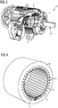
- the electric machine has according to FIG. 3 a stator 8 and a rotor 9.
- the rotor 9 is rotatably mounted on a rotor shaft 10, which in turn is rotatable about a rotation axis.
- the stator 8 has according to the 3 and 4 Statornuten 11 on.
- a stator winding 12 in the stator 11 is a stator winding 12 (see FIG. 3 ) brought in.
- the stator winding 12 has coils 13 (see FIG. 4 ), where in FIG. 4 for the sake of clarity, only one of the coils 13 is shown.
- the embodiment of the coil 13 is the actual subject of the present invention.
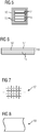
- the coil 13 is according to FIG. 5 of a number of windings 14.
- the windings 14 are usually made of copper, often copper tape. In any case, the windings 14 are provided with a non-specifically illustrated electrical insulation, such as a protective coating.
- the number of turns 14 may be as needed. In the FIG. 5 shown number of four turns 14 is purely exemplary.
- the windings 14 are according to FIG. 5 - And not individually, but together - wound with a number of layers of a mica tape 15.
- the number of layers of the mica tape 15 may be 1. Often it is greater than 1.
- the in FIG. 5 however, the number of two layers shown is purely exemplary.
- the number of layers of the shroud 16 may be greater than 1. As a rule, however, only one layer is wound on shroud 16.
- the shroud 16 is usually the outermost layer of the finished coil 13. After winding the coil 13 with the shroud 16 so the finished coil 13 is inserted into the stator 9 or more precisely in two of the stator 11.
- the mica tape 15 should have the highest possible flexibility and the lowest possible static coefficient of friction between the top and bottom.
- the bending stiffness according to DIN EN 60371-2 (as of 2005) should be less than 50 N / m.
- the static friction coefficient (defined in the same standard) should be less than 0.7.
- suitable mica tapes are RikaFibrel E364N and RikaFibrel E464N from the Nippon Rika Group.
- the mica tape 15 has the above-mentioned material properties permanently. At least at the time of manufacture of the coil 13, however, the material properties of the mica tape 15 must be given.
- the static friction coefficient can be effected at the time of manufacturing the coil 13 by a grease or oil layer between the layers of the mica tape 15.
- a grease or oil layer is still present even after the production of the coil 13, ie volatilizes only after a longer period of time, so that even with applications of a grease or oil layer of the corresponding static friction coefficient can be regarded as a material property of the mica tape 15.
- the above statements apply to the mica tape 15 also for the shroud 16.
- the shroud 16 between its top and bottom underside a static friction coefficient according to DIN EN ISO 8295 (as of 2004) of less than 0.7.
- the shroud 16 and the mica tape 15 are preferably matched to one another in such a way that the shroud 16 has such a static friction coefficient towards the mica tape 15.
- the shroud 16 is according to the FIGS. 6 to 8 preferably formed as a laminate having a sequence of two layers 17, 18. Depending on one of these two layers 17, 18 is a fabric 17 and a film 18. Further constituents does not contain the shroud 16. The film 18 thus directly adjoins the fabric 17. As a rule, the fabric 17 faces away from the layers of the mica tape 15 and, correspondingly, the film 18 faces the layers of the mica tape 15. In principle, however, the reverse sequence of tissue 17 and 18 film is possible.
- the fabric 17 is preferably made of a glass fiber. Alternatively, it may consist of a first high performance polymer.
- the first high performance polymer may be a polyimide, but is preferably an aramid, especially a meta (m) aramid or a para (p) aramid.
- the film 18 is made of a second high performance polymer.
- the second high performance polymer may be an aramid, especially a meta (m) aramid or a para (p) aramid.
- the second high performance polymer is a polyimide.
- An example of a suitable shroud 16 is Voltaflex GK2797 from Isovolta AG.
- the coil 13, as in FIG. 4 is recognizable, designed as a three-dimensional shape coil.
- the coil 13 is first wound in a step S1 as a plane coil. This is indicated in step S1 by the indication "2D".
- the plane coil is purely exemplary in FIG. 10 shown.
- the layers of mica tape 15 and shroud 16 are applied to the planar coil, that is to say prior to deformation to the shaping coil. This is indicated in step S2 by the statement "15, 16".
- the already wound flat coil is formed into a three-dimensional shaping coil. This is indicated in step S3 by the indication "3D".
- the layers of the mica tape 15 shift with each other and / or the layers of the shroud 16 against each other.
- the innermost layer of the shroud 16 adjoining the outermost layer of the mica tape 15 also shifts against each other.
- the displacements are a constructive feature of the coils 13 resulting from the manufacturing process.
- a specific thermal class according to IEC 60034-18-31 (as of 2017) can be achieved.
- Each additional layer of mica tape 15 increases the thermal class.
- the mica tape 15 and the number of layers of the mica tape 15 are coordinated so that the coil 13 has a thermal class of 200 ° C or better (according to said standard).
- the present invention thus relates to the following facts:
- a coil 13 of a stator winding 12 of an electrical machine 4 consists of a number of windings 14 co-wound with a number of layers of mica tape 15 on which in turn a number of layers of shroud 16 are wound.
- the coil 13 is formed as a three-dimensional shaping coil.
- the mica tape 15 has a bending stiffness according to DIN EN 60371-2, 2005, of less than 50 N / m and between its top and bottom a coefficient of static friction according to DIN EN ISO 8295 as of 2004 of less than 0.7.
- the present invention has many advantages.
- electrical machines 4 with forming coils 13 can be used for the first time, which are wound with mica tape 15 and shroud 16 before the three-dimensional shaping process.
- Wet resistance and temperature index are significantly improved.
- a thermal class of 200 ° C or better can be achieved.
- the mechanical protection is improved.
Landscapes
- Engineering & Computer Science (AREA)
- Power Engineering (AREA)
- Transportation (AREA)
- Mechanical Engineering (AREA)
- Insulation, Fastening Of Motor, Generator Windings (AREA)
- Insulating Bodies (AREA)
Abstract
Description
- Die vorliegende Erfindung geht aus von einer Spule einer Statorwicklung einer elektrischen Maschine,
- wobei die Spule aus einer Anzahl von Windungen besteht, die gemeinsam mit einer Anzahl von Schichten eines Glimmerbandes bewickelt sind, auf die wiederum eine Anzahl von Schichten eines Deckbandes gewickelt ist,
- wobei die Spule als dreidimensionale Formspule ausgebildet ist.
- Die vorliegende Erfindung geht weiterhin aus von einer elektrischen Maschine, wobei die elektrische Maschine einen Stator und einen Rotor aufweist, wobei der Stator Statornuten aufweist, in die eine Statorwicklung eingebracht ist, wobei die Statorwicklung Spulen aufweist, wobei mindestens eine der Spulen als Spule wie obenstehend beschrieben ausgebildet ist.
- Die vorliegende Erfindung geht weiterhin aus von einem elektrischen Antrieb, wobei der Antrieb eine derartige elektrische Maschine, einen Umrichter und eine Steuereinrichtung für den Umrichter aufweist, wobei die elektrische Maschine von der Steuereinrichtung über den Umrichter an eine Versorgungsspannung anschaltbar ist, die größer als 350 V ist, insbesondere größer als 1,0 kV, beispielsweise bis zu 4,5 kV.
- Die vorliegende Erfindung geht weiterhin aus von einem Schienenfahrzeug, wobei das Schienenfahrzeug als Traktionsantrieb einen derartigen elektrischen Antrieb aufweist.
- Bei elektrischen Maschinen werden auf die Spulen der Statorwicklung zur Hauptisolation eine oder mehrere Lagen an Glimmerband aufgebracht. Dies erfolgt unter anderem, um die Nässeresistenz und die Wärmeklasse der Spule zu steigern. Insbesondere bei elektrischen Maschinen, die als Traktionsantrieb von Schienenfahrzeugen verwendet werden, wird dieser Aufbau zusätzlich durch eine Lage eines Gewebe-Deckbandes vor mechanischen Einflüssen geschützt. Das Gewebe-Deckband weist ausschließlich eine mechanische Schutzfunktion auf. Die Nässeresistenz und die Wärmeklasse der Hauptisolierung werden hingegen maßgeblich durch die Anzahl an Lagen an Glimmerband bestimmt.
- Bei als Formspulen ausgebildeten Spulen ist es bekannt, zunächst eine plane Spule zu fertigen, die aufgrund ihrer Form üblicherweise als race track-Schleife (zwei lange Geraden, die über zwei halbkreisförmig gebogene Abschnitte miteinander verbunden sind) bezeichnet wird. Diese Spule wird sodann durch einen Formgebungsprozess in die Formspule umgeformt. Bei derartigen Formspulen ist es weiterhin bekannt, die Lagen an Glimmerband nach dem Formen der (dreidimensionalen) Formspule auf die Spule aufzubringen. Dieser Vorgang erfolgt in der Regel manuell. Das manuelle Aufbringen des Glimmerbandes ist zeitaufwendig und fehlerträchtig.
- Es ist bereits versucht worden, die Lagen an Glimmerband vor dem Formen der dreidimensionalen Formspule auf die dann noch plane Spule aufzubringen und die bereits mit Glimmerband (und gegebenenfalls auch dem Deckband) bewickelte plane Spule zur Formspule zu formen. Diese Vorgehensweise ist als Flattechnik bekannt. Bei Spulen für elektrische Antriebe, die bei "normalen" Anwendungen eingesetzt werden, hat sich diese Vorgehensweise als machbar erwiesen. Für Traktionsantriebe und ähnliche Anwendungen, bei denen die elektrische Maschine des Antriebs rauen Umweltbedingungen ausgesetzt ist, war es bisher jedoch nicht möglich, auf diese Weise Formspulen herzustellen, die in der Praxis die erforderliche Zuverlässigkeit - insbesondere Nässeresistenz - aufweisen.
- Die Aufgabe der vorliegenden Erfindung besteht darin, Möglichkeiten zur Verfügung zu stellen, mittels derer auf einfache und kostengünstige Weise Formspulen, elektrische Maschinen und Antriebe geschaffen werden können, die insbesondere für eine Verwendung bei Traktionsantrieben geeignet sind.
- Die Aufgabe wird durch eine Spule mit den Merkmalen des Anspruchs 1 gelöst. Vorteilhafte Ausgestaltungen der Spule sind Gegenstand der abhängigen Ansprüche 2 bis 5.
- Erfindungsgemäß wird eine Spule der eingangs genannten Art dadurch ausgestaltet, dass das Glimmerband eine Biegesteifigkeit nach DIN EN 60371-2 (Stand 2005) von unter 50 N/m und zwischen seiner Oberseite und seiner Unterseite einen Haftreibungskoeffizienten nach DIN EN ISO 8295 (Stand 2004) von unter 0,7 aufweist.
- Durch die Verwendung eines derart flexiblen Glimmerbandes wird erreicht, dass das Glimmerband sich beim Bewickeln der noch planen Spule nahezu faltenfrei an die noch plane Spule anlegt. Dadurch ist es möglich, dass die Lagen an Glimmerband sich beim Formen der planen Spule zur Formspule gegeneinander verschieben können, ohne dass Lagen an Falten hängen bleiben. Durch die Verwendung eines Glimmerbandes mit entsprechenden Haftreibungskoeffizienten wird erreicht, dass die Lagen des Glimmerbandes sich beim Formen der Spule zur Formspule in reproduzierbarer Weise gegeneinander verschieben. Insbesondere kann durch die Kombination dieser beiden Eigenschaften somit erreicht werden, dass beim Formen der Spule zur Formspule keine Lücken entstehen, dass also die eigentliche Spule (= die Anzahl an Windungen von metallischen Leitern, meist Leitern aus flachem Kupferband) überall zuverlässig noch von einer hinreichenden Anzahl an Lagen des Glimmerbandes abgedeckt bleiben.
- In der Regel ist es ausreichend, wenn das Glimmerband die obengenannten Eigenschaften aufweist. Es kann jedoch von Vorteil sein, diese Eigenschaften auch beim Deckband zu realisieren. Es kann also von Vorteil sein, dass das Deckband zwischen seiner Oberseite und seiner Unterseite einen Haftreibungskoeffizienten nach DIN EN ISO 8295 (Stand 2004) von unter 0,7 aufweist und/oder dass das Deckband und das Glimmerband derart aufeinander abgestimmt sind, dass das Deckband zum Glimmerband hin einen Haftreibungskoeffizienten nach DIN EN ISO 8295 (Stand 2004) von unter 0,7 aufweist.
- Vorzugsweise sind das Glimmerband und die Anzahl an Lagen des Glimmerbandes derart aufeinander abgestimmt, dass die Spule eine Wärmeklasse von 200°C oder besser nach IEC 60034-18-31 (Stand 2017) aufweist. Dies stellt eine Verbesserung gegenüber dem Stand der Technik dar, bei dem typischerweise eine Wärmeklasse von 180°C erreichbar ist. Es ist ohne weiteres eine Wärmeklasse von 220°, in manchen Fällen sogar eine Wärmeklasse von 250° realisierbar.
- In einer bevorzugten Ausgestaltung der Spule weist das Deckband in sich zwei Schichten auf, wobei je eine dieser beiden Schichten ein Gewebe und eine Folie ist, das Gewebe aus einer Glasfaser oder aus einem ersten Hochleistungspolymer besteht und die Folie aus einem zweiten Hochleistungspolymer besteht. Durch diese Ausgestaltung kann erreicht werden, dass Deckband nicht nur eine mechanische, sondern - wenn auch nur in relativ geringem Umfang - eine elektrische Schutzfunktion bewirkt und dennoch eine hohe Wärmeklasse realisiert werden kann. Das zweite Hochleistungspolymer kann insbesondere ein Polyimid sein. In der Regel ist hierbei das Gewebe von den Schichten des Glimmerbandes abgewandt, die Folie den Schichten des Glimmerbandes zugewandt.
- Die Aufgabe wird weiterhin durch eine elektrische Maschine mit den Merkmalen des Anspruchs 6 gelöst. Erfindungsgemäß ist bei einer elektrischen Maschine der eingangs genannten Art mindestens eine der Spulen erfindungsgemäß ausgebildet.
- Die Aufgabe wird weiterhin durch einen elektrischen Antrieb mit den Merkmalen des Anspruchs 7 gelöst. Erfindungsgemäß ist die elektrische Maschine des elektrischen Antriebs erfindungsgemäß ausgebildet.
- Die Aufgabe wird weiterhin durch ein Schienenfahrzeug mit den Merkmalen des Anspruchs 8 gelöst. Erfindungsgemäß weist das Schienenfahrzeug als Traktionsantrieb einen erfindungsgemäßen elektrischen Antrieb auf.
- Die oben beschriebenen Eigenschaften, Merkmale und Vorteile dieser Erfindung sowie die Art und Weise, wie diese erreicht werden, werden klarer und deutlicher verständlich im Zusammenhang mit der folgenden Beschreibung der Ausführungsbeispiele, die in Verbindung mit den Zeichnungen näher erläutert werden. Hierbei zeigen in schematischer Darstellung:
- FIG 1
- ein Schienenfahrzeug,
- FIG 2
- einen elektrischen Antrieb
- FIG 3
- eine elektrische Maschine,
- FIG 4
- einen Stator einer elektrischen Maschine und eine Spule,
- FIG 5
- einen Querschnitt durch eine Spule,
- FIG 6
- eine Abfolge von Schichten von Bändern,
- FIG 7
- eine Draufsicht auf eine Oberseite eines Deckbandes,
- FIG 8
- eine Draufsicht auf eine Unterseite eines Deckbandes,
- FIG 9
- ein Ablaufdiagramm und
- FIG 10
- eine plane Spule.
- Gemäß
FIG 1 weist ein Schienenfahrzeug 1 (beispielsweise eine Elektrolok) mindestens einen Traktionsantrieb 2 auf. Der Traktionsantrieb 2 wird gemäßFIG 1 über eine Oberleitung 3 mit elektrischer Energie versorgt. Es ist jedoch auch eine andere Art der Versorgung denkbar, beispielsweise über einen Dieselantrieb, der einen elektrischen Generator antreibt. - Der Traktionsantrieb 2 ist ein Beispiel eines elektrischen Antriebs. In Verbindung mit dem Traktionsantrieb 2 wird die vorliegende Erfindung nachstehend erläutert. Der elektrische Antrieb könnte jedoch auch für andere Zwecke verwendet werden. Nachstehend werden daher nur allgemein die Bezeichnung "Antrieb" verwendet und weiterhin das Bezugszeichen 2 verwendet.
- Der elektrische Antrieb 2 weist gemäß
FIG 2 eine elektrische Maschine 4, einen Umrichter 5 und eine Steuereinrichtung 6 für den Umrichter 5 auf. In vielen Fällen ist dem Umrichter 5 weiterhin ein Gleichrichter 7 vorgeordnet. Dies ist jedoch nicht zwingend erforderlich. Von der Steuereinrichtung 6 ist die elektrische Maschine 4 über den Umrichter 5 an eine Versorgungsspannung U anschaltbar. Falls der Gleichrichter 7 vorhanden ist und steuerbar ist, erfolgt die Steuerung des Gleichrichters 7 in der Regel ebenfalls durch die Steuereinrichtung 6. - Die Versorgungsspannung U - also diejenige Spannung, welche an die Motorklemmen der elektrischen Maschine 4 angelegt wird - ist in der Regel größer als 350 V, insbesondere meist grö-ßer als 1 kV. Sie kann sogar größer als 1,0 kV sein, bei- spielsweise zwischen 2 kV und 3 kV liegen. In manchen Fällen kann sie bis zu 4,5 kV betragen.
- Die elektrische Maschine weist gemäß
FIG 3 einen Stator 8 und einen Rotor 9 auf. Der Rotor 9 ist auf einer Rotorwelle 10 drehfest angeordnet, die ihrerseits um eine Rotationsachse rotierbar ist. Der Stator 8 weist gemäß denFIG 3 und 4 Statornuten 11 auf. In die Statornuten 11 ist eine Statorwicklung 12 (sieheFIG 3 ) eingebracht. Die Statorwicklung 12 weist Spulen 13 (sieheFIG 4 ) auf, wobei inFIG 4 der Übersichtlichkeit halber nur eine der Spulen 13 dargestellt ist. Die Ausgestaltung der Spule 13 ist der eigentliche Gegenstand der vorliegenden Erfindung. - Die Spule 13 besteht gemäß
FIG 5 aus einer Anzahl von Windungen 14. Die Windungen 14 bestehen üblicherweise aus Kupfer, oftmals aus Kupferband. In jedem Fall aber sind die Windungen 14 mit einer nicht eigens dargestellten elektrischen Isolierung versehen, beispielsweise einem Schutzlack. Die Anzahl an Windungen 14 kann nach Bedarf sein. Die inFIG 5 dargestellte Anzahl von vier Windungen 14 ist rein beispielhaft. - Die Windungen 14 sind gemäß
FIG 5 - und zwar nicht einzeln, sondern gemeinsam - mit einer Anzahl von Schichten eines Glimmerbandes 15 bewickelt. Die Anzahl an Schichten des Glimmerbandes 15 kann 1 sein. Oftmals ist sie größer als 1. Die inFIG 5 dargestellte Anzahl von zwei Schichten ist jedoch rein beispielhaft. Auf die Schichten an Glimmerband 15 - genau genommen auf die äußerste Schicht an Glimmerband 15 - ist eine Anzahl von Schichten eines Deckbandes 16 gewickelt. Die Anzahl an Schichten des Deckbandes 16 kann größer als 1 sein. In der Regel ist jedoch nur eine Schicht an Deckband 16 gewickelt. Das Deckband 16 ist in der Regel die äußerste Schicht der fertigen Spule 13. Nach dem Bewickeln der Spule 13 mit dem Deckband 16 wird also die fertige Spule 13 in den Stator 9 bzw. genauer in zwei der Statornuten 11 eingesetzt. - Falls die Spule 13 in der sogenannten Flattechnik hergestellt wird, sollte das Glimmerband 15 eine möglichst hohe Biegsamkeit und einen möglichst geringen Haftreibungskoeffizienten zwischen Oberseite und Unterseite aufweisen. Insbesondere sollte die Biegesteifigkeit nach DIN EN 60371-2 (Stand 2005) unter 50 N/m liegen. Der Haftreibungskoeffizient (definiert in derselben Norm) sollte unter 0,7 liegen. Beispiele geeigneter Glimmerbänder sind RikaFibrel E364N und RikaFibrel E464N der Nippon Rika Group.
- Es ist möglich, dass das Glimmerband 15 die obengenannten Materialeigenschaften permanent aufweist. Zumindest zum Zeitpunkt der Herstellung der Spule 13 müssen die Materialeigenschaften des Glimmerbandes 15 jedoch gegeben sein. Insbesondere der Haftreibungskoeffizient kann zum Zeitpunkt der Herstellung der Spule 13 auch durch eine Fett- oder Ölschicht zwischen den Schichten des Glimmerbandes 15 bewirkt werden. Eine derartige Fett- oder Ölschicht ist jedoch auch nach der Herstellung der Spule 13 noch vorhanden, verflüchtigt sich also erst nach einem längeren Zeitraum, so dass auch bei Applikationen einer Fett- oder Ölschicht der entsprechende Haftreibungskoeffizient als Materialeigenschaft des Glimmerbandes 15 angesehen werden kann.
- Vorzugsweise gelten die obigen Ausführungen zum Glimmerband 15 auch für das Deckband 16. Vorzugsweise weist also auch das Deckband 16 zwischen seiner Oberseite und seiner Unterseite einen Haftreibungskoeffizienten nach DIN EN ISO 8295 (Stand 2004) von unter 0,7 auf. Weiterhin sind vorzugsweise das Deckband 16 und das Glimmerband 15 derart aufeinander abgestimmt, dass das Deckband 16 zum Glimmerband 15 hin einen derartigen Haftreibungskoeffizienten aufweist. Die obigen Aussagen zur Applikation von Fett- und Ölschichten sind auch hier gültig.
- Das Deckband 16 ist gemäß den
FIG 6 bis 8 vorzugsweise als Laminat ausgebildet, das eine Abfolge von zwei Schichten 17, 18 aufweist. Je eine dieser beiden Schichten 17, 18 ist ein Gewebe 17 und eine Folie 18. Weitere Bestandteile enthält das Deckband 16 nicht. Die Folie 18 grenzt also unmittelbar an das Gewebe 17 an. In der Regel ist das Gewebe 17 von den Schichten des Glimmerbandes 15 abgewandt und hiermit korrespondierend die Folie 18 den Schichten des Glimmerbandes 15 zugewandt. Prinzipiell ist jedoch auch die umgekehrte Abfolge von Gewebe 17 und Folie 18 möglich. - Das Gewebe 17 besteht vorzugsweise aus einer Glasfaser. Alternativ kann es aus einem ersten Hochleistungspolymer bestehen. Das erste Hochleistungspolymer kann ein Polyimid sein, ist aber vorzugsweise ein Aramid, insbesondere ein meta(m)-Aramid oder ein para(p)-Aramid. Die Folie 18 besteht aus einem zweiten Hochleistungspolymer. Das zweite Hochleistungspolymer kann ein Aramid sein, insbesondere ein meta(m)-Aramid oder ein para(p)-Aramid. Vorzugsweise ist das zweite Hochleistungspolymer jedoch ein Polyimid. Ein Beispiel eines geeigneten Deckbandes 16 ist Voltaflex GK2797 der Isovolta AG.
- Erfindungsgemäß ist die Spule 13, wie in
FIG 4 erkennbar ist, als dreidimensionale Formspule ausgebildet. Erfindungsgemäß wird weiterhin entsprechend der Darstellung inFIG 9 die Spule 13 zunächst in einem Schritt S1 als plane Spule gewickelt. Dies ist im Schritt S1 durch die Angabe "2D" angedeutet. Die plane Spule ist rein beispielhaft inFIG 10 dargestellt. Danach werden in einem Schritt S2 auf die plane Spule, also vor dem Verformen zur Formspule, die Schichten an Glimmerband 15 und Deckband 16 aufgebracht. Dies ist im Schritt S2 durch die Angabe "15, 16" angedeutet. Erst danach wird in einem Schritt S3 die bereits bewickelte flache Spule zur dreidimensionalen Formspule geformt. Dies ist im Schritt S3 durch die Angabe "3D" angedeutet. - Bei dem Formgebungsprozess (Schritt S3) verschieben sich die Schichten des Glimmerbandes 15 untereinander und/oder die Schichten des Deckbandes 16 gegeneinander. In manchen Fällen verschieben sich auch die an die äußerste Schicht des Glimmerbandes 15 angrenzende innerste Schicht des Deckbandes 16 gegeneinander. Die Verschiebungen sind ein sich durch den Herstellungsprozess ergebendes konstruktives Merkmal der Spulen 13.
- Mit einer einzelnen Lage an Glimmerband 15 kann eine bestimmte Wärmeklasse nach IEC 60034-18-31(Stand 2017) erreicht werden. Jede weitere Lage an Glimmerband 15 erhöht die Wärmeklasse. Vorzugsweise sind das Glimmerband 15 und die Anzahl an Lagen des Glimmerbandes 15 derart aufeinander abgestimmt, dass die Spule 13 eine Wärmeklasse von 200°C oder besser (gemäß der genannten Norm) aufweist.
- Zusammengefasst betrifft die vorliegende Erfindung somit folgenden Sachverhalt:
- Eine Spule 13 einer Statorwicklung 12 einer elektrischen Maschine 4 besteht aus einer Anzahl von Windungen 14, die gemeinsam mit einer Anzahl von Schichten eines Glimmerbandes 15 bewickelt sind, auf die wiederum eine Anzahl von Schichten eines Deckbandes 16 gewickelt ist. Die Spule 13 ist als dreidimensionale Formspule ausgebildet. Das Glimmerband 15 weist eine Biegesteifigkeit nach DIN EN 60371-2 Stand 2005 von unter 50 N/m und zwischen seiner Oberseite und seiner Unterseite einen Haftreibungskoeffizienten nach DIN EN ISO 8295 Stand 2004 von unter 0,7 auf.
- Die vorliegende Erfindung weist viele Vorteile auf. Insbesondere können für Traktionsantriebe 2 und ähnliche Anwendungsfälle erstmals elektrische Maschinen 4 mit Formspulen 13 verwendet werden, die vor dem dreidimensionalen Formgebungsprozess mit Glimmerband 15 und Deckband 16 bewickelt werden. Die Nässeresistenz und der Temperaturindex werden signifikant verbessert. Insbesondere lässt sich eine Wärmeklasse von 200°C oder besser erreichen. Weiterhin wird auch der mechanische Schutz verbessert.
- Obwohl die Erfindung im Detail durch das bevorzugte Ausführungsbeispiel näher illustriert und beschrieben wurde, so ist die Erfindung nicht durch die offenbarten Beispiele eingeschränkt und andere Variationen können vom Fachmann hieraus abgeleitet werden, ohne den Schutzumfang der Erfindung zu verlassen.
Claims (8)
- Spule einer Statorwicklung (12) einer elektrischen Maschine (4),- wobei die Spule aus einer Anzahl von Windungen (14) besteht, die gemeinsam mit einer Anzahl von Schichten eines Glimmerbandes (15) bewickelt sind, auf die wiederum eine Anzahl von Schichten eines Deckbandes (16) gewickelt ist,- wobei die Spule als dreidimensionale Formspule ausgebildet ist,dadurch gekennzeichnet,
dass das Glimmerband (15) eine Biegesteifigkeit nach DIN EN 60371-2 (Stand 2005) von unter 50 N/m und zwischen seiner Oberseite und seiner Unterseite einen Haftreibungskoeffizienten nach DIN EN ISO 8295 (Stand 2004) von unter 0,7 aufweist. - Spule nach Anspruch 1,
dadurch gekennzeichnet,
dass das Deckband (16) zwischen seiner Oberseite und seiner Unterseite einen Haftreibungskoeffizienten nach DIN EN ISO 8295 (Stand 2004) von unter 0,7 aufweist und/oder dass das Deckband (16) und das Glimmerband (15) derart aufeinander abgestimmt sind, dass das Deckband (16) zum Glimmerband (15) hin einen Haftreibungskoeffizienten nach DIN EN ISO 8295 (Stand 2004) von unter 0,7 aufweist. - Spule nach Anspruch 1 oder 2,
dadurch gekennzeichnet,
dass das Glimmerband (15) und die Anzahl an Lagen des Glimmerbandes (15) derart aufeinander abgestimmt sind, dass die Spule eine Wärmeklasse von 200°C oder besser nach IEC 60034-18-31 (Stand 2017) aufweist. - Spule nach Anspruch 1, 2 oder 3,
dadurch gekennzeichnet,
dass das Deckband (16) in sich zwei Schichten (17, 18) aufweist, dass je eine dieser beiden Schichten (17, 18 ein Gewebe (17) und eine Folie (18) ist und dass das Gewebe (17) aus einer Glasfaser oder aus einem ersten Hochleistungspolymer besteht und die Folie (18) aus einem zweiten Hochleistungspolymer besteht. - Spule nach Anspruch 4,
dadurch gekennzeichnet,
dass das zweite Hochleistungspolymer ein Polyimid ist. - Elektrische Maschine, wobei die elektrische Maschine einen Stator (8) und einen Rotor (9) aufweist, wobei der Stator (8) Statornuten (11) aufweist, in die eine Statorwicklung (12) eingebracht ist, wobei die Statorwicklung (12) Spulen (13) aufweist, wobei mindestens eine der Spulen (13) als Spule nach einem der Ansprüche 1 bis 5 ausgebildet ist.
- Elektrischer Antrieb, wobei der elektrische Antrieb eine elektrische Maschine (4) nach Anspruch 6, einen Umrichter (5) und eine Steuereinrichtung (6) für den Umrichter (5) aufweist, wobei die elektrische Maschine (4) von der Steuereinrichtung (6) über den Umrichter (5) an eine Versorgungsspannung (U) anschaltbar ist, die größer als 350 V ist, insbesondere größer als 1,0 kV, beispielsweise bis zu 4,5 kV.
- Schienenfahrzeug, wobei das Schienenfahrzeug als Traktionsantrieb (2) einen elektrischen Antrieb nach Anspruch 7 aufweist.
Priority Applications (5)
| Application Number | Priority Date | Filing Date | Title |
|---|---|---|---|
| EP17182597.9A EP3432450B1 (de) | 2017-07-21 | 2017-07-21 | Formspule mit vorheriger bewicklung mit glimmerband |
| ES17182597T ES2902402T3 (es) | 2017-07-21 | 2017-07-21 | Bobina de molde con bobinado anterior con cinta de mica |
| PCT/EP2018/067043 WO2019015922A1 (de) | 2017-07-21 | 2018-06-26 | Formspule mit vorheriger bewicklung mit glimmerband |
| US16/632,575 US11496011B2 (en) | 2017-07-21 | 2018-06-26 | Form-wound coil having previous winding of mica tape |
| CN201880048294.1A CN110945756B (zh) | 2017-07-21 | 2018-06-26 | 具有事先用云母带缠绕的成型线圈 |
Applications Claiming Priority (1)
| Application Number | Priority Date | Filing Date | Title |
|---|---|---|---|
| EP17182597.9A EP3432450B1 (de) | 2017-07-21 | 2017-07-21 | Formspule mit vorheriger bewicklung mit glimmerband |
Publications (2)
| Publication Number | Publication Date |
|---|---|
| EP3432450A1 true EP3432450A1 (de) | 2019-01-23 |
| EP3432450B1 EP3432450B1 (de) | 2021-09-29 |
Family
ID=59384057
Family Applications (1)
| Application Number | Title | Priority Date | Filing Date |
|---|---|---|---|
| EP17182597.9A Active EP3432450B1 (de) | 2017-07-21 | 2017-07-21 | Formspule mit vorheriger bewicklung mit glimmerband |
Country Status (5)
| Country | Link |
|---|---|
| US (1) | US11496011B2 (de) |
| EP (1) | EP3432450B1 (de) |
| CN (1) | CN110945756B (de) |
| ES (1) | ES2902402T3 (de) |
| WO (1) | WO2019015922A1 (de) |
Cited By (1)
| Publication number | Priority date | Publication date | Assignee | Title |
|---|---|---|---|---|
| EP3955423A1 (de) * | 2020-08-10 | 2022-02-16 | Siemens Aktiengesellschaft | Elektrische maschine mit wicklungen aus litzenleitern |
Citations (4)
| Publication number | Priority date | Publication date | Assignee | Title |
|---|---|---|---|---|
| US2479357A (en) * | 1945-01-10 | 1949-08-16 | Westinghouse Electric Corp | Method of making electrical insulations |
| CH559451A5 (de) * | 1973-05-17 | 1975-02-28 | Bbc Brown Boveri & Cie | |
| JPS60237828A (ja) * | 1984-05-11 | 1985-11-26 | Toshiba Corp | 回転電機コイル |
| JPH02156605A (ja) * | 1988-12-09 | 1990-06-15 | Hitachi Ltd | 電気機器用絶縁線輪 |
Family Cites Families (4)
| Publication number | Priority date | Publication date | Assignee | Title |
|---|---|---|---|---|
| US3254150A (en) * | 1961-07-24 | 1966-05-31 | Westinghouse Electric Corp | Electrical coils for refrigerating apparatus |
| US4038741A (en) | 1973-05-17 | 1977-08-02 | Bbc Brown Boveri & Company Limited | Method of making electrical coils for dynamo-electric machines having band-formed insulation material |
| CN201266506Y (zh) | 2008-12-22 | 2009-07-01 | 长沙长利电工材料有限责任公司 | 一种电磁线及线圈绕组 |
| CN104485767B (zh) | 2014-12-15 | 2017-05-17 | 哈尔滨电气动力装备有限公司 | 高压电机定子线圈绝缘结构及其浸渍和固化工艺 |
-
2017
- 2017-07-21 ES ES17182597T patent/ES2902402T3/es active Active
- 2017-07-21 EP EP17182597.9A patent/EP3432450B1/de active Active
-
2018
- 2018-06-26 US US16/632,575 patent/US11496011B2/en active Active
- 2018-06-26 CN CN201880048294.1A patent/CN110945756B/zh active Active
- 2018-06-26 WO PCT/EP2018/067043 patent/WO2019015922A1/de not_active Ceased
Patent Citations (4)
| Publication number | Priority date | Publication date | Assignee | Title |
|---|---|---|---|---|
| US2479357A (en) * | 1945-01-10 | 1949-08-16 | Westinghouse Electric Corp | Method of making electrical insulations |
| CH559451A5 (de) * | 1973-05-17 | 1975-02-28 | Bbc Brown Boveri & Cie | |
| JPS60237828A (ja) * | 1984-05-11 | 1985-11-26 | Toshiba Corp | 回転電機コイル |
| JPH02156605A (ja) * | 1988-12-09 | 1990-06-15 | Hitachi Ltd | 電気機器用絶縁線輪 |
Non-Patent Citations (1)
| Title |
|---|
| GARNIER: "NIPPNRIKA", 25 April 2017 (2017-04-25), pages 1 - 15, XP055439671, Retrieved from the Internet <URL:http://www.fiee.com.br/__novadocuments/354804?v=636287423822970000> [retrieved on 20180110] * |
Cited By (1)
| Publication number | Priority date | Publication date | Assignee | Title |
|---|---|---|---|---|
| EP3955423A1 (de) * | 2020-08-10 | 2022-02-16 | Siemens Aktiengesellschaft | Elektrische maschine mit wicklungen aus litzenleitern |
Also Published As
| Publication number | Publication date |
|---|---|
| ES2902402T3 (es) | 2022-03-28 |
| US20200244128A1 (en) | 2020-07-30 |
| EP3432450B1 (de) | 2021-09-29 |
| CN110945756B (zh) | 2022-07-08 |
| CN110945756A (zh) | 2020-03-31 |
| US11496011B2 (en) | 2022-11-08 |
| WO2019015922A1 (de) | 2019-01-24 |
Similar Documents
| Publication | Publication Date | Title |
|---|---|---|
| WO2008087093A1 (de) | Leiterstab für den stator eines generators sowie verfahren zu seiner herstellung | |
| EP2976772A1 (de) | Lackdraht | |
| EP0898805B1 (de) | Leiterwicklungsanordnung für eine elektrische grossmaschine | |
| CH707458A2 (de) | Feldspulenwicklungsanordnung. | |
| EP0133220A2 (de) | Elektrischer Leiter | |
| DE102007053685A1 (de) | Herstellungsverfahren für eine mehrlagige Transformatorwicklung mit Isolationsschicht | |
| EP3432450B1 (de) | Formspule mit vorheriger bewicklung mit glimmerband | |
| DE102019109516A1 (de) | Wicklung und Verfahren zur Herstellung einer Wicklung | |
| DE102008044416A1 (de) | Statorkernkeil mit Kappe und zugehöriges Verfahren | |
| WO2010006670A1 (de) | Wicklung für einen transformator | |
| DE102020207226A1 (de) | Verfahren zum Herstellen eines Bauteils einer elektrischen Maschine | |
| DE19860412A1 (de) | Innenglimmschutz für Statorleiter in Motoren und Generatoren | |
| EP1305867A1 (de) | Wicklungen für elektrische maschinen mit leitern aus litze | |
| EP1371124B1 (de) | Verfahren zum herstellen eines leiterstabes | |
| EP2705095B1 (de) | Isolationslack und isolationslaminat | |
| DE102006049420A1 (de) | Elektrische Maschine | |
| DE102017202188A1 (de) | Elektrische Leitung | |
| EP3432451A1 (de) | Spule mit deckband aus hochleistungsmaterial | |
| EP2842141B1 (de) | Selbsttragende elektrische leitung | |
| DE10323099A1 (de) | Verfahren zum Herstellen einer Wicklung | |
| EP1364215B1 (de) | Induktives bauelement und ein verfahren zu dessen herstellung | |
| DE102017007501A1 (de) | Blechpaketeinrichtung für eine elektrische Maschine, sowie Verfahren zum Herstellen einer solchen Blechpaketeinrichtung | |
| DE102023135341A1 (de) | Verfahren zur Herstellung einer Wicklung für eine elektrische Maschine | |
| DE102022214072A1 (de) | Verfahren zur Herstellung einer elektrischen Maschine | |
| DE102023104290A1 (de) | Verfahren zur Herstellung eines Elektromagneten |
Legal Events
| Date | Code | Title | Description |
|---|---|---|---|
| PUAI | Public reference made under article 153(3) epc to a published international application that has entered the european phase |
Free format text: ORIGINAL CODE: 0009012 |
|
| STAA | Information on the status of an ep patent application or granted ep patent |
Free format text: STATUS: THE APPLICATION HAS BEEN PUBLISHED |
|
| AK | Designated contracting states |
Kind code of ref document: A1 Designated state(s): AL AT BE BG CH CY CZ DE DK EE ES FI FR GB GR HR HU IE IS IT LI LT LU LV MC MK MT NL NO PL PT RO RS SE SI SK SM TR |
|
| AX | Request for extension of the european patent |
Extension state: BA ME |
|
| RAP1 | Party data changed (applicant data changed or rights of an application transferred) |
Owner name: SIEMENS MOBILITY GMBH |
|
| STAA | Information on the status of an ep patent application or granted ep patent |
Free format text: STATUS: REQUEST FOR EXAMINATION WAS MADE |
|
| 17P | Request for examination filed |
Effective date: 20190722 |
|
| RBV | Designated contracting states (corrected) |
Designated state(s): AL AT BE BG CH CY CZ DE DK EE ES FI FR GB GR HR HU IE IS IT LI LT LU LV MC MK MT NL NO PL PT RO RS SE SI SK SM TR |
|
| STAA | Information on the status of an ep patent application or granted ep patent |
Free format text: STATUS: EXAMINATION IS IN PROGRESS |
|
| 17Q | First examination report despatched |
Effective date: 20200909 |
|
| GRAP | Despatch of communication of intention to grant a patent |
Free format text: ORIGINAL CODE: EPIDOSNIGR1 |
|
| STAA | Information on the status of an ep patent application or granted ep patent |
Free format text: STATUS: GRANT OF PATENT IS INTENDED |
|
| INTG | Intention to grant announced |
Effective date: 20210503 |
|
| GRAS | Grant fee paid |
Free format text: ORIGINAL CODE: EPIDOSNIGR3 |
|
| GRAA | (expected) grant |
Free format text: ORIGINAL CODE: 0009210 |
|
| STAA | Information on the status of an ep patent application or granted ep patent |
Free format text: STATUS: THE PATENT HAS BEEN GRANTED |
|
| AK | Designated contracting states |
Kind code of ref document: B1 Designated state(s): AL AT BE BG CH CY CZ DE DK EE ES FI FR GB GR HR HU IE IS IT LI LT LU LV MC MK MT NL NO PL PT RO RS SE SI SK SM TR |
|
| REG | Reference to a national code |
Ref country code: GB Ref legal event code: FG4D Free format text: NOT ENGLISH |
|
| REG | Reference to a national code |
Ref country code: CH Ref legal event code: EP Ref country code: AT Ref legal event code: REF Ref document number: 1435077 Country of ref document: AT Kind code of ref document: T Effective date: 20211015 |
|
| REG | Reference to a national code |
Ref country code: DE Ref legal event code: R096 Ref document number: 502017011591 Country of ref document: DE |
|
| REG | Reference to a national code |
Ref country code: IE Ref legal event code: FG4D Free format text: LANGUAGE OF EP DOCUMENT: GERMAN |
|
| REG | Reference to a national code |
Ref country code: LT Ref legal event code: MG9D |
|
| PG25 | Lapsed in a contracting state [announced via postgrant information from national office to epo] |
Ref country code: LT Free format text: LAPSE BECAUSE OF FAILURE TO SUBMIT A TRANSLATION OF THE DESCRIPTION OR TO PAY THE FEE WITHIN THE PRESCRIBED TIME-LIMIT Effective date: 20210929 Ref country code: BG Free format text: LAPSE BECAUSE OF FAILURE TO SUBMIT A TRANSLATION OF THE DESCRIPTION OR TO PAY THE FEE WITHIN THE PRESCRIBED TIME-LIMIT Effective date: 20211229 Ref country code: HR Free format text: LAPSE BECAUSE OF FAILURE TO SUBMIT A TRANSLATION OF THE DESCRIPTION OR TO PAY THE FEE WITHIN THE PRESCRIBED TIME-LIMIT Effective date: 20210929 Ref country code: FI Free format text: LAPSE BECAUSE OF FAILURE TO SUBMIT A TRANSLATION OF THE DESCRIPTION OR TO PAY THE FEE WITHIN THE PRESCRIBED TIME-LIMIT Effective date: 20210929 Ref country code: NO Free format text: LAPSE BECAUSE OF FAILURE TO SUBMIT A TRANSLATION OF THE DESCRIPTION OR TO PAY THE FEE WITHIN THE PRESCRIBED TIME-LIMIT Effective date: 20211229 Ref country code: RS Free format text: LAPSE BECAUSE OF FAILURE TO SUBMIT A TRANSLATION OF THE DESCRIPTION OR TO PAY THE FEE WITHIN THE PRESCRIBED TIME-LIMIT Effective date: 20210929 Ref country code: SE Free format text: LAPSE BECAUSE OF FAILURE TO SUBMIT A TRANSLATION OF THE DESCRIPTION OR TO PAY THE FEE WITHIN THE PRESCRIBED TIME-LIMIT Effective date: 20210929 |
|
| REG | Reference to a national code |
Ref country code: NL Ref legal event code: MP Effective date: 20210929 |
|
| PG25 | Lapsed in a contracting state [announced via postgrant information from national office to epo] |
Ref country code: LV Free format text: LAPSE BECAUSE OF FAILURE TO SUBMIT A TRANSLATION OF THE DESCRIPTION OR TO PAY THE FEE WITHIN THE PRESCRIBED TIME-LIMIT Effective date: 20210929 Ref country code: GR Free format text: LAPSE BECAUSE OF FAILURE TO SUBMIT A TRANSLATION OF THE DESCRIPTION OR TO PAY THE FEE WITHIN THE PRESCRIBED TIME-LIMIT Effective date: 20211230 |
|
| REG | Reference to a national code |
Ref country code: ES Ref legal event code: FG2A Ref document number: 2902402 Country of ref document: ES Kind code of ref document: T3 Effective date: 20220328 |
|
| PG25 | Lapsed in a contracting state [announced via postgrant information from national office to epo] |
Ref country code: IS Free format text: LAPSE BECAUSE OF FAILURE TO SUBMIT A TRANSLATION OF THE DESCRIPTION OR TO PAY THE FEE WITHIN THE PRESCRIBED TIME-LIMIT Effective date: 20220129 Ref country code: SK Free format text: LAPSE BECAUSE OF FAILURE TO SUBMIT A TRANSLATION OF THE DESCRIPTION OR TO PAY THE FEE WITHIN THE PRESCRIBED TIME-LIMIT Effective date: 20210929 Ref country code: RO Free format text: LAPSE BECAUSE OF FAILURE TO SUBMIT A TRANSLATION OF THE DESCRIPTION OR TO PAY THE FEE WITHIN THE PRESCRIBED TIME-LIMIT Effective date: 20210929 Ref country code: PT Free format text: LAPSE BECAUSE OF FAILURE TO SUBMIT A TRANSLATION OF THE DESCRIPTION OR TO PAY THE FEE WITHIN THE PRESCRIBED TIME-LIMIT Effective date: 20220131 Ref country code: PL Free format text: LAPSE BECAUSE OF FAILURE TO SUBMIT A TRANSLATION OF THE DESCRIPTION OR TO PAY THE FEE WITHIN THE PRESCRIBED TIME-LIMIT Effective date: 20210929 Ref country code: NL Free format text: LAPSE BECAUSE OF FAILURE TO SUBMIT A TRANSLATION OF THE DESCRIPTION OR TO PAY THE FEE WITHIN THE PRESCRIBED TIME-LIMIT Effective date: 20210929 Ref country code: EE Free format text: LAPSE BECAUSE OF FAILURE TO SUBMIT A TRANSLATION OF THE DESCRIPTION OR TO PAY THE FEE WITHIN THE PRESCRIBED TIME-LIMIT Effective date: 20210929 Ref country code: CZ Free format text: LAPSE BECAUSE OF FAILURE TO SUBMIT A TRANSLATION OF THE DESCRIPTION OR TO PAY THE FEE WITHIN THE PRESCRIBED TIME-LIMIT Effective date: 20210929 Ref country code: AL Free format text: LAPSE BECAUSE OF FAILURE TO SUBMIT A TRANSLATION OF THE DESCRIPTION OR TO PAY THE FEE WITHIN THE PRESCRIBED TIME-LIMIT Effective date: 20210929 |
|
| REG | Reference to a national code |
Ref country code: DE Ref legal event code: R097 Ref document number: 502017011591 Country of ref document: DE |
|
| PG25 | Lapsed in a contracting state [announced via postgrant information from national office to epo] |
Ref country code: DK Free format text: LAPSE BECAUSE OF FAILURE TO SUBMIT A TRANSLATION OF THE DESCRIPTION OR TO PAY THE FEE WITHIN THE PRESCRIBED TIME-LIMIT Effective date: 20210929 |
|
| PLBE | No opposition filed within time limit |
Free format text: ORIGINAL CODE: 0009261 |
|
| STAA | Information on the status of an ep patent application or granted ep patent |
Free format text: STATUS: NO OPPOSITION FILED WITHIN TIME LIMIT |
|
| 26N | No opposition filed |
Effective date: 20220630 |
|
| PG25 | Lapsed in a contracting state [announced via postgrant information from national office to epo] |
Ref country code: SI Free format text: LAPSE BECAUSE OF FAILURE TO SUBMIT A TRANSLATION OF THE DESCRIPTION OR TO PAY THE FEE WITHIN THE PRESCRIBED TIME-LIMIT Effective date: 20210929 |
|
| PG25 | Lapsed in a contracting state [announced via postgrant information from national office to epo] |
Ref country code: MC Free format text: LAPSE BECAUSE OF FAILURE TO SUBMIT A TRANSLATION OF THE DESCRIPTION OR TO PAY THE FEE WITHIN THE PRESCRIBED TIME-LIMIT Effective date: 20210929 |
|
| REG | Reference to a national code |
Ref country code: CH Ref legal event code: PL |
|
| REG | Reference to a national code |
Ref country code: BE Ref legal event code: MM Effective date: 20220731 |
|
| PG25 | Lapsed in a contracting state [announced via postgrant information from national office to epo] |
Ref country code: LU Free format text: LAPSE BECAUSE OF NON-PAYMENT OF DUE FEES Effective date: 20220721 Ref country code: LI Free format text: LAPSE BECAUSE OF NON-PAYMENT OF DUE FEES Effective date: 20220731 Ref country code: CH Free format text: LAPSE BECAUSE OF NON-PAYMENT OF DUE FEES Effective date: 20220731 |
|
| PG25 | Lapsed in a contracting state [announced via postgrant information from national office to epo] |
Ref country code: BE Free format text: LAPSE BECAUSE OF NON-PAYMENT OF DUE FEES Effective date: 20220731 |
|
| PG25 | Lapsed in a contracting state [announced via postgrant information from national office to epo] |
Ref country code: IE Free format text: LAPSE BECAUSE OF NON-PAYMENT OF DUE FEES Effective date: 20220721 |
|
| PG25 | Lapsed in a contracting state [announced via postgrant information from national office to epo] |
Ref country code: HU Free format text: LAPSE BECAUSE OF FAILURE TO SUBMIT A TRANSLATION OF THE DESCRIPTION OR TO PAY THE FEE WITHIN THE PRESCRIBED TIME-LIMIT; INVALID AB INITIO Effective date: 20170721 |
|
| PG25 | Lapsed in a contracting state [announced via postgrant information from national office to epo] |
Ref country code: SM Free format text: LAPSE BECAUSE OF FAILURE TO SUBMIT A TRANSLATION OF THE DESCRIPTION OR TO PAY THE FEE WITHIN THE PRESCRIBED TIME-LIMIT Effective date: 20210929 Ref country code: MK Free format text: LAPSE BECAUSE OF FAILURE TO SUBMIT A TRANSLATION OF THE DESCRIPTION OR TO PAY THE FEE WITHIN THE PRESCRIBED TIME-LIMIT Effective date: 20210929 Ref country code: CY Free format text: LAPSE BECAUSE OF FAILURE TO SUBMIT A TRANSLATION OF THE DESCRIPTION OR TO PAY THE FEE WITHIN THE PRESCRIBED TIME-LIMIT Effective date: 20210929 |
|
| PG25 | Lapsed in a contracting state [announced via postgrant information from national office to epo] |
Ref country code: MT Free format text: LAPSE BECAUSE OF FAILURE TO SUBMIT A TRANSLATION OF THE DESCRIPTION OR TO PAY THE FEE WITHIN THE PRESCRIBED TIME-LIMIT Effective date: 20210929 |
|
| REG | Reference to a national code |
Ref country code: DE Ref legal event code: R081 Ref document number: 502017011591 Country of ref document: DE Owner name: SIEMENS MOBILITY GMBH, DE Free format text: FORMER OWNER: SIEMENS MOBILITY GMBH, 81739 MUENCHEN, DE |
|
| PGFP | Annual fee paid to national office [announced via postgrant information from national office to epo] |
Ref country code: DE Payment date: 20250919 Year of fee payment: 9 |
|
| PGFP | Annual fee paid to national office [announced via postgrant information from national office to epo] |
Ref country code: IT Payment date: 20250718 Year of fee payment: 9 |
|
| PGFP | Annual fee paid to national office [announced via postgrant information from national office to epo] |
Ref country code: GB Payment date: 20250811 Year of fee payment: 9 |
|
| PGFP | Annual fee paid to national office [announced via postgrant information from national office to epo] |
Ref country code: AT Payment date: 20250606 Year of fee payment: 9 Ref country code: FR Payment date: 20250716 Year of fee payment: 9 |
|
| PG25 | Lapsed in a contracting state [announced via postgrant information from national office to epo] |
Ref country code: TR Free format text: LAPSE BECAUSE OF FAILURE TO SUBMIT A TRANSLATION OF THE DESCRIPTION OR TO PAY THE FEE WITHIN THE PRESCRIBED TIME-LIMIT Effective date: 20210929 |
|
| PGFP | Annual fee paid to national office [announced via postgrant information from national office to epo] |
Ref country code: ES Payment date: 20251020 Year of fee payment: 9 |