EP3431908B1 - Method for precisely positioning an inner casing in an external casing of an air conditioned cabinet and air conditioned cabinet - Google Patents
Method for precisely positioning an inner casing in an external casing of an air conditioned cabinet and air conditioned cabinet Download PDFInfo
- Publication number
- EP3431908B1 EP3431908B1 EP18177570.1A EP18177570A EP3431908B1 EP 3431908 B1 EP3431908 B1 EP 3431908B1 EP 18177570 A EP18177570 A EP 18177570A EP 3431908 B1 EP3431908 B1 EP 3431908B1
- Authority
- EP
- European Patent Office
- Prior art keywords
- component
- leg
- vessel
- boiler
- outer vessel
- Prior art date
- Legal status (The legal status is an assumption and is not a legal conclusion. Google has not performed a legal analysis and makes no representation as to the accuracy of the status listed.)
- Active
Links
Images

Classifications
-
- F—MECHANICAL ENGINEERING; LIGHTING; HEATING; WEAPONS; BLASTING
- F24—HEATING; RANGES; VENTILATING
- F24F—AIR-CONDITIONING; AIR-HUMIDIFICATION; VENTILATION; USE OF AIR CURRENTS FOR SCREENING
- F24F13/00—Details common to, or for air-conditioning, air-humidification, ventilation or use of air currents for screening
- F24F13/20—Casings or covers
-
- F—MECHANICAL ENGINEERING; LIGHTING; HEATING; WEAPONS; BLASTING
- F25—REFRIGERATION OR COOLING; COMBINED HEATING AND REFRIGERATION SYSTEMS; HEAT PUMP SYSTEMS; MANUFACTURE OR STORAGE OF ICE; LIQUEFACTION SOLIDIFICATION OF GASES
- F25D—REFRIGERATORS; COLD ROOMS; ICE-BOXES; COOLING OR FREEZING APPARATUS NOT OTHERWISE PROVIDED FOR
- F25D23/00—General constructional features
- F25D23/06—Walls
- F25D23/062—Walls defining a cabinet
- F25D23/063—Walls defining a cabinet formed by an assembly of panels
-
- F—MECHANICAL ENGINEERING; LIGHTING; HEATING; WEAPONS; BLASTING
- F24—HEATING; RANGES; VENTILATING
- F24F—AIR-CONDITIONING; AIR-HUMIDIFICATION; VENTILATION; USE OF AIR CURRENTS FOR SCREENING
- F24F13/00—Details common to, or for air-conditioning, air-humidification, ventilation or use of air currents for screening
-
- B—PERFORMING OPERATIONS; TRANSPORTING
- B01—PHYSICAL OR CHEMICAL PROCESSES OR APPARATUS IN GENERAL
- B01L—CHEMICAL OR PHYSICAL LABORATORY APPARATUS FOR GENERAL USE
- B01L7/00—Heating or cooling apparatus; Heat insulating devices
-
- B—PERFORMING OPERATIONS; TRANSPORTING
- B23—MACHINE TOOLS; METAL-WORKING NOT OTHERWISE PROVIDED FOR
- B23P—METAL-WORKING NOT OTHERWISE PROVIDED FOR; COMBINED OPERATIONS; UNIVERSAL MACHINE TOOLS
- B23P15/00—Making specific metal objects by operations not covered by a single other subclass or a group in this subclass
- B23P15/26—Making specific metal objects by operations not covered by a single other subclass or a group in this subclass heat exchangers or the like
-
- F—MECHANICAL ENGINEERING; LIGHTING; HEATING; WEAPONS; BLASTING
- F25—REFRIGERATION OR COOLING; COMBINED HEATING AND REFRIGERATION SYSTEMS; HEAT PUMP SYSTEMS; MANUFACTURE OR STORAGE OF ICE; LIQUEFACTION SOLIDIFICATION OF GASES
- F25B—REFRIGERATION MACHINES, PLANTS OR SYSTEMS; COMBINED HEATING AND REFRIGERATION SYSTEMS; HEAT PUMP SYSTEMS
- F25B41/00—Fluid-circulation arrangements
- F25B41/20—Disposition of valves, e.g. of on-off valves or flow control valves
-
- F—MECHANICAL ENGINEERING; LIGHTING; HEATING; WEAPONS; BLASTING
- F25—REFRIGERATION OR COOLING; COMBINED HEATING AND REFRIGERATION SYSTEMS; HEAT PUMP SYSTEMS; MANUFACTURE OR STORAGE OF ICE; LIQUEFACTION SOLIDIFICATION OF GASES
- F25D—REFRIGERATORS; COLD ROOMS; ICE-BOXES; COOLING OR FREEZING APPARATUS NOT OTHERWISE PROVIDED FOR
- F25D23/00—General constructional features
- F25D23/06—Walls
- F25D23/065—Details
- F25D23/066—Liners
-
- F—MECHANICAL ENGINEERING; LIGHTING; HEATING; WEAPONS; BLASTING
- F25—REFRIGERATION OR COOLING; COMBINED HEATING AND REFRIGERATION SYSTEMS; HEAT PUMP SYSTEMS; MANUFACTURE OR STORAGE OF ICE; LIQUEFACTION SOLIDIFICATION OF GASES
- F25D—REFRIGERATORS; COLD ROOMS; ICE-BOXES; COOLING OR FREEZING APPARATUS NOT OTHERWISE PROVIDED FOR
- F25D23/00—General constructional features
- F25D23/06—Walls
- F25D23/065—Details
- F25D23/067—Supporting elements
-
- F—MECHANICAL ENGINEERING; LIGHTING; HEATING; WEAPONS; BLASTING
- F25—REFRIGERATION OR COOLING; COMBINED HEATING AND REFRIGERATION SYSTEMS; HEAT PUMP SYSTEMS; MANUFACTURE OR STORAGE OF ICE; LIQUEFACTION SOLIDIFICATION OF GASES
- F25D—REFRIGERATORS; COLD ROOMS; ICE-BOXES; COOLING OR FREEZING APPARATUS NOT OTHERWISE PROVIDED FOR
- F25D31/00—Other cooling or freezing apparatus
- F25D31/005—Combined cooling and heating devices
-
- Y—GENERAL TAGGING OF NEW TECHNOLOGICAL DEVELOPMENTS; GENERAL TAGGING OF CROSS-SECTIONAL TECHNOLOGIES SPANNING OVER SEVERAL SECTIONS OF THE IPC; TECHNICAL SUBJECTS COVERED BY FORMER USPC CROSS-REFERENCE ART COLLECTIONS [XRACs] AND DIGESTS
- Y10—TECHNICAL SUBJECTS COVERED BY FORMER USPC
- Y10T—TECHNICAL SUBJECTS COVERED BY FORMER US CLASSIFICATION
- Y10T29/00—Metal working
- Y10T29/49—Method of mechanical manufacture
- Y10T29/4935—Heat exchanger or boiler making
- Y10T29/49359—Cooling apparatus making, e.g., air conditioner, refrigerator
Definitions
- the invention relates to a method for precisely positioning an inner boiler in the outer boiler of a climate chamber and climate chamber.
- the DE 10 2009 002796 A1 discloses a method for precisely positioning a shelf module in a refrigeration appliance with the features of the preamble of patent claim 1 and a refrigeration appliance with the features of the preamble of patent claim 3.
- the object of the invention is therefore to provide a method for precisely positioning an inner vessel in the outer vessel of a climate chamber and a climate chamber with an inner vessel that can be positioned precisely.
- This task is solved by a process for precise positioning an inner boiler in the outer boiler of a climate cabinet with the features of claim 1 and by a climate cabinet with a precisely positioned inner boiler with the features of claim 3.
- Advantageous developments of the invention are the subject of the respective dependent claims.
- climate cabinet is understood here to mean any cabinet-like device in the interior of which a temperature that deviates from the ambient conditions can be set.
- climate chambers usually have a heating and/or cooling device, which can be arranged at least in sections - for example with a cooling or heating coil - in the interior of the outer boiler, preferably between the outer boiler and the inner boiler.
- At least the interior of the inner boiler is usually accessible through doors or flaps; the direction from which it is accessible specifies a loading direction.
- the external boiler can in particular be provided in such a way that the external boiler already installed in the later climate cabinet is provided complete with the later climate cabinet and the heating and/or cooling device;
- the external boiler can also be provided preconfigured as an individual component with more or fewer additional add-on parts.
- An outdoor boiler typically has at least two side walls, a floor and a ceiling and possibly also a rear wall.
- the inner boiler can be formed in one piece, which then results in the only component of the inner boiler being the inner boiler itself. Typically, however, it is made up of several individual parts or components, for example side walls, between which an inner rear wall or a floor is then held. But it can also only have side walls.
- the precise positioning takes place by shifting the position of the foot in a plane parallel to the bottom of the outer boiler, it being particularly preferred that the displacement of the position of the foot takes place in a direction parallel to the component of the inner boiler on which the Foot is arranged.
- This can in particular be the direction of a side wall of the inner boiler that is parallel to the access direction if it has the foot or feet.
- the climate cabinet according to the invention has an outer boiler with a ceiling and a floor, the distance between which defines the height of an interior of the outer boiler, an inner boiler arranged in the outer boiler and a heating and / or cooling device arranged at least in sections between the outer boiler and the inner boiler.
- an outer boiler with a ceiling and a floor, the distance between which defines the height of an interior of the outer boiler, an inner boiler arranged in the outer boiler and a heating and / or cooling device arranged at least in sections between the outer boiler and the inner boiler.
- it can also have doors, an outer skin, a frame or feet.
- At least one component of the inner boiler - for example a side wall - has a lower height than the height of the interior of the outer boiler predetermined by the distance between the ceiling and the floor of the outer boiler, with at least one foot being movably arranged on this component in such a way that that the height of the at least one provided component of the inner boiler, including the at least one foot arranged thereon, is variable, so that by changing the position of the at least one foot when the component of the inner boiler is arranged in the outer boiler, a precisely fitting positioning can be achieved, in which the component of the inner boiler is supported on the ceiling of the outer boiler and the at least one foot is supported on the floor of the outer boiler and that the at least one foot can be fixed in this position with a fixing means.
- the advantage of this special design is, in particular, that the arrangement of the inner boiler adapted to the outer boiler can be achieved with very good accuracy through simple work steps.
- such a climate cabinet is when the at least one foot is arranged on the component of the inner boiler in such a way that the height of the at least one provided component of the inner boiler with the at least one foot arranged thereon varies by a displacement parallel to the plane defined by the bottom of the outer boiler can be, it being preferred if the at least one foot is arranged on the component of the inner boiler in such a way that the height of the at least one provided component of the inner boiler with the at least one foot arranged thereon is increased by a displacement parallel to the component of the inner boiler which the foot is arranged can be varied.
- such an arrangement of the foot on the component of the inner boiler can be achieved in that the component of the inner boiler has at least one bolt and that the at least one foot has an elongated hole in which the bolt is guided, the distance of the elongated hole from that The end of the foot facing the bottom of the outer boiler varies.
- the component of the inner boiler is then pushed upwards and thus adapted to the expansion of the respective external boiler.
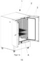
- FIG 1a shows a climate cabinet 1 with doors 3 open, so that a view of the interior of the climate cabinet is clear. It can be seen that the climate cabinet 1 has an outer boiler 10, in which an inner boiler 2 composed of components 21 is arranged. In this exemplary embodiment of a climate cabinet 1, shelves 4 are arranged on the inner boiler 3. The heating and/or cooling device of the climate cabinet 1 is shown in the illustration Figure 1a not recognizable because it is covered by your inner boiler 3 or its components 21.
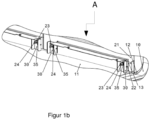
- Figure 1b shows a section A of the view into the interior of the climate cabinet 1, more precisely into its front right bottom corner. You can see a section of the outer boiler 10 and from its bottom 11 and the transition area 12 to its right side wall 13, which is largely covered by a component 21 of the inner boiler 2, here the right side wall of the inner boiler 2.
- the component 21 of the inner boiler 2 obviously does not stand directly on the floor 11 of the outer boiler 10, but is supported there by several feet 30, which immediately and necessarily results in the fact that the component 21 of the inner boiler 2 has a lower height than that through the Distance between the in Figure 1 unrecognizable ceiling and the floor 11 of the outer boiler 10 predetermined height of the interior of the outer boiler 10.
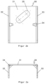
- the foot 30 has an approximately U-shaped cross section with a back 31 and two side walls 32, 33 which are perpendicular to the surface of the back 31 and which are secured against bending with reinforcements 34.
- the back 31 of the foot 30 there is an elongated hole 35 running obliquely from the top right to the bottom left.
- a component 21 of the inner boiler 2 which can be easily inserted into the outer boiler 10 because of its lower height, can simply be pre-positioned there and precisely fitted into the outer boiler 10 from the access direction simply by applying pressure to the easily accessible side walls 32, 33 of the foot 30 , which significantly simplifies this step in the manufacturing process.
Landscapes
- Engineering & Computer Science (AREA)
- Mechanical Engineering (AREA)
- General Engineering & Computer Science (AREA)
- Chemical & Material Sciences (AREA)
- Combustion & Propulsion (AREA)
- Physics & Mathematics (AREA)
- Thermal Sciences (AREA)
- Health & Medical Sciences (AREA)
- Clinical Laboratory Science (AREA)
- Chemical Kinetics & Catalysis (AREA)
- Devices That Are Associated With Refrigeration Equipment (AREA)
- Air Filters, Heat-Exchange Apparatuses, And Housings Of Air-Conditioning Units (AREA)
- Cooling Or The Like Of Electrical Apparatus (AREA)
Description
Die Erfindung betrifft ein Verfahren zur passgenauen Positionierung eines Innenkessels im Außenkessel eines Klimaschranks und Klimaschrank.The invention relates to a method for precisely positioning an inner boiler in the outer boiler of a climate chamber and climate chamber.
Klimaschränke mit einem Innenkessel, einem Außenkessel und einer zumindest abschnittsweise zwischen Außenkessel und Innenkessel angeordneten Heiz- und/oder Kühlvorrichtung sind seit vielen Jahren, beispielsweise aus der
Die
Die Aufgabe der Erfindung besteht daher darin, ein Verfahren zur passgenauen Positionierung eines Innenkessels im Außenkessel eines Klimaschranks und einen Klimaschrank mit passgenau positionierbarem Innenkessel bereitzustellen. Diese Aufgabe wird gelöst durch ein Verfahren zur passgenauen Positionierung eines Innenkessels im Außenkessel eines Klimaschranks mit den Merkmalen des Anspruchs 1 und durch einen Klimaschrank mit passgenau positionierbarem Innenkessel mit den Merkmalen des Anspruchs 3. Vorteilhafte Weiterbildungen der Erfindung sind Gegenstand der jeweiligen abhängigen Ansprüche.The object of the invention is therefore to provide a method for precisely positioning an inner vessel in the outer vessel of a climate chamber and a climate chamber with an inner vessel that can be positioned precisely. This task is solved by a process for precise positioning an inner boiler in the outer boiler of a climate cabinet with the features of
Das erfindungsgemäße Verfahren zur passgenauen Positionierung eines Innenkessels im Außenkessel eines Klimaschranks weist die folgenden Schritte auf:
- Bereitstellen eines Außenkessels mit einer Decke und einem der Decke gegenüber liegenden Boden,
- Bereitstellen mindestens einer Komponente eines Innenkessels, und
- Positionieren der mindestens einen Komponente des Innenkessels zwischen Decke und Boden im Außenkessel.
- Providing an outdoor boiler with a ceiling and a floor opposite the ceiling,
- Providing at least one component of an inner boiler, and
- Positioning the at least one component of the inner boiler between the ceiling and floor in the outer boiler.
Erfindungswesentlich ist,
- dass mindestens eine Komponente des Innenkessels bereitgestellt wird, die eine geringere Höhe hat als die durch den Abstand zwischen der Decke und dem Boden des Außenkessels vorgegebene Höhe des Innenraums des Außenkessels und an der mindestens ein Fuß derart beweglich angeordnet ist, dass die Höhe der mindestens einen bereitgestellten Komponente des Innenkessels einschließlich dem mindestens einen daran beweglich angeordneten Fuß variabel ist,
- dass durch eine Veränderung der Position des mindestens einen Fußes bei in dem Außenkessel angeordneter Komponente des Innenkessels eine passgenaue Positionierung herbeigeführt wird, bei der die Komponente des Innenkessels an der Decke des Außenkessels abgestützt ist und der mindestens eine Fuß an dem Boden des Außenkessels abgestützt ist,
- dass der Fuß in der Position, in der er die passgenaue Positionierung herbeiführt, fixiert wird, und
- dass die passgenaue Positionierung durch eine Verschiebung der Position des Fußes in einer zum Boden des Außenkessels parallelen Ebene erfolgt.
- that at least one component of the inner boiler is provided which has a lower height than the height of the interior of the outer boiler predetermined by the distance between the ceiling and the floor of the outer boiler and on which at least one foot is movably arranged in such a way that the height of the at least one provided component of the inner boiler including the at least one foot movably arranged thereon is variable,
- that by changing the position of the at least one foot when the component of the inner boiler is arranged in the outer boiler, a precisely fitting positioning is achieved is, in which the component of the inner boiler is supported on the ceiling of the outer boiler and at least one foot is supported on the floor of the outer boiler,
- that the foot is fixed in the position in which it achieves the precise positioning, and
- that the precise positioning is achieved by shifting the position of the foot in a plane parallel to the bottom of the outer boiler.
Es wird also der bisher stets verwendete Ansatz, die Komponente des Innenkessels möglichst exakt an die entsprechende Dimension des Außenkessels anzupassen aufgegeben und stattdessen bewußt eine "zu kleine" Komponente des Innenkessels verwendet, die erst durch das Einstellen der beweglich an der Komponente des Innenkessels angeordneten Füße passgenau mit der Decke des Außenkessels in Kontakt gebracht wird. Dies ermöglicht nicht nur, die jeweiligen Toleranzen des Außenkessels zu kompensieren, sondern erweist sich auch als deutlich einfacher im Hinblick auf die Durchführung dieses Arbeitsschritts, da sich das Einführen einer passgenau zum Außenkessel dimensionierten Komponente des Innenkessels oftmals als schwierig erweist. Grundsätzlich sei an dieser Stelle angemerkt, dass der Begriff "Klimaschrank" breit zu verstehen ist. Unter einem Klimaschrank wird hier jede schrankartige Vorrichtung verstanden, in deren Innenraum eine von den Umgebungsbedingungen abweichende Temperatur einstellbar ist. Dazu weisen Klimaschränke in der Regel eine Heiz- und/oder Kühlvorrichtung auf, die zumindest abschnittsweise -also beispielsweise mit einer Kühl- oder Heizschlange- im Innenraum des Außenkessels, vorzugsweise zwischen Außenkessel und Innenkessel angeordnet sein kann. Zumindest der Innenraum des Innenkessels ist üblicherweise durch Türen oder Klappen zugänglich; die Richtung, aus der er zugänglich ist, gibt eine Beladungsrichtung vor.The previously always used approach of adapting the component of the inner boiler as precisely as possible to the corresponding dimension of the outer boiler is therefore abandoned and instead a component of the inner boiler that is "too small" is deliberately used, which is only possible by adjusting the feet that are movably arranged on the component of the inner boiler is brought into precise contact with the ceiling of the outer boiler. This not only makes it possible to compensate for the respective tolerances of the outer boiler, but also proves to be significantly easier in terms of carrying out this work step, since introducing a component of the inner boiler that is dimensioned precisely to the outer boiler often proves to be difficult. Basically, it should be noted at this point that the term “climate cabinet” is to be understood broadly. A climate cabinet is understood here to mean any cabinet-like device in the interior of which a temperature that deviates from the ambient conditions can be set. For this purpose, climate chambers usually have a heating and/or cooling device, which can be arranged at least in sections - for example with a cooling or heating coil - in the interior of the outer boiler, preferably between the outer boiler and the inner boiler. At least the interior of the inner boiler is usually accessible through doors or flaps; the direction from which it is accessible specifies a loading direction.
Dementsprechend kann insbesondere das Bereitstellen des Außenkessels so erfolgen, dass der bereits in den späteren Klimaschrank eingebaute Außenkessels komplett mit dem späteren Klimaschrank und der Heiz- und/oder Kühlvorrichtung bereitgestellt wird; es kann aber auch der Außenkessel als Einzelkomponente mit mehr oder weniger zusätzlichen Anbauteilen vorkonfiguriert bereitgestellt werden.Accordingly, the external boiler can in particular be provided in such a way that the external boiler already installed in the later climate cabinet is provided complete with the later climate cabinet and the heating and/or cooling device; However, the external boiler can also be provided preconfigured as an individual component with more or fewer additional add-on parts.
Ein Außenkessel weist typischerweise mindestens zwei Seitenwände, einen Boden und eine Decke sowie gegebenenfalls auch eine Rückwand auf.An outdoor boiler typically has at least two side walls, a floor and a ceiling and possibly also a rear wall.
Der Innenkessel kann einstückig ausgeformt sein, was dann dazu führt, dass die einzige Komponente des Innenkessels der Innenkessel selbst ist. Typischerweise ist er aber aus mehreren Einzelteilen oder Komponenten aufgebaut, beispielsweise aus Seitenwänden, zwischen denen dann eine innere Rückwand oder ein Boden gehalten wird. Er kann aber auch nur Seitenwände aufweisen.The inner boiler can be formed in one piece, which then results in the only component of the inner boiler being the inner boiler itself. Typically, however, it is made up of several individual parts or components, for example side walls, between which an inner rear wall or a floor is then held. But it can also only have side walls.
Erfindungsgemäß ist vorgesehen, dass die passgenaue Positionierung durch eine Verschiebung der Position des Fußes in einer zum Boden des Außenkessels parallelen Ebene erfolgt, wobei besonders bevorzugt ist, dass die Verschiebung der Position des Fußes in Richtung parallel zu der Komponente des Innenkessels erfolgt, an der der Fuß angeordnet ist. Dies kann insbesondere die zur Zugangsrichtung parallele Verlaufsrichtung einer Seitenwand des Innenkessels sein, wenn diese den oder die Füße aufweist. Vorteilhaft sind diese Maßnahmen deshalb, weil die "Arbeitsrichtung", in die man Kraft ausüben muss, um die passgenaue Einpassung der Komponente des Innenkessels zu erreichen, die Zugangsrichtung ist, was die Kraftausübung erleichtert. Beispielsweise kann durch eine Lagerung der Füße in einem schräg zum Boden des Außenkessels verlaufenden Langloch oder Schlitz, in dem ein an der entsprechenden Komponente, insbesondere an einer Seitenwand, des Innenkessels gelagerter Bolzen geführt ist, die passgenaue Anordnung durch Druck in Zugangs- oder Beladungsrichtung des Klimaschranks herbeigeführt werden, während beispielsweise bei Schraubfüßen ein unpraktisches Herumfingern notwendig wäre, um in Bodennähe befindliche Schrauben anzuziehen.According to the invention it is provided that the precise positioning takes place by shifting the position of the foot in a plane parallel to the bottom of the outer boiler, it being particularly preferred that the displacement of the position of the foot takes place in a direction parallel to the component of the inner boiler on which the Foot is arranged. This can in particular be the direction of a side wall of the inner boiler that is parallel to the access direction if it has the foot or feet. These measures are advantageous because the "working direction" in which force must be exerted in order to achieve the precise fit of the component of the inner boiler is the access direction, which makes the application of force easier. For example, by positioning the feet in... an elongated hole or slot running obliquely to the bottom of the outer boiler, in which a bolt mounted on the corresponding component, in particular on a side wall, of the inner boiler is guided, the precise arrangement can be brought about by pressure in the access or loading direction of the climate cabinet, while, for example, with screw feet an inconvenient fumbling would be necessary to tighten screws that are close to the floor.
Der erfindungsgemäße Klimaschrank hat einen Außenkessel mit einer Decke und einem Boden, deren Abstand die Höhe eines Innenraums des Außenkessels definiert, einen in dem Außenkessel angeordneten Innenkessel und eine zumindest abschnittsweise zwischen dem Außenkessel und dem Innenkessel angeordneten Heiz- und/oder Kühlvorrichtung. Selbstverständlich kann er darüber hinaus, wie bei Klimaschränken weit verbreitet, zusätzlich Türen, eine Außenhaut, ein Gestell oder Füße aufweisen.The climate cabinet according to the invention has an outer boiler with a ceiling and a floor, the distance between which defines the height of an interior of the outer boiler, an inner boiler arranged in the outer boiler and a heating and / or cooling device arranged at least in sections between the outer boiler and the inner boiler. Of course, as is common with climate chambers, it can also have doors, an outer skin, a frame or feet.
Erfindungswesentlich ist, dass mindestens eine Komponente des Innenkessels -beispielsweise eine Seitenwand- eine geringere Höhe hat als die durch den Abstand zwischen der Decke und dem Boden des Außenkessels vorgegebene Höhe des Innenraums des Außenkessels, wobei an dieser Komponente mindestens ein Fuß derart beweglich angeordnet ist, dass die Höhe der mindestens einen bereitgestellten Komponente des Innenkessels einschließlich des mindestens einen daran angeordneten Fußes variabel ist, so dass durch eine Veränderung der Position des mindestens einen Fußes bei in dem Außenkessel angeordneter Komponente des Innenkessels eine passgenaue Positionierung herbeigeführt werden kann, bei der die Komponente des Innenkessels an der Decke des Außenkessels abgestützt ist und der mindestens eine Fuß an dem Boden des Außenkessels abgestützt ist und dass der mindestens eine Fuß mit einem Fixiermittel in dieser Position fixierbar ist. Der Vorteil dieser speziellen Augestaltung liegt insbesondere darin, dass die an den Außenkessel angepasste Anordnung des Innenkessels durch einfache Arbeitsschritte mit sehr guter Genauigkeit erreicht werden kann.It is essential to the invention that at least one component of the inner boiler - for example a side wall - has a lower height than the height of the interior of the outer boiler predetermined by the distance between the ceiling and the floor of the outer boiler, with at least one foot being movably arranged on this component in such a way that that the height of the at least one provided component of the inner boiler, including the at least one foot arranged thereon, is variable, so that by changing the position of the at least one foot when the component of the inner boiler is arranged in the outer boiler, a precisely fitting positioning can be achieved, in which the component of the inner boiler is supported on the ceiling of the outer boiler and the at least one foot is supported on the floor of the outer boiler and that the at least one foot can be fixed in this position with a fixing means. The advantage of this special design is, in particular, that the arrangement of the inner boiler adapted to the outer boiler can be achieved with very good accuracy through simple work steps.
Erfindungsgemäß ist ein solcher Klimaschrank, wenn der mindestens eine Fuß so an der Komponente des Innenkessels angeordnet ist, dass die Höhe der mindestens einen bereitgestellten Komponente des Innenkessels mit dem mindestens einen daran angeordneten Fuß durch eine Verschiebung parallel zur durch den Boden des Außenkessels definierten Ebene variiert werden kann, wobei es bevorzugt ist, wenn der mindestens eine Fuß so an der Komponente des Innenkessels angeordnet ist, dass die Höhe der mindestens einen bereitgestellten Komponente des Innenkessels mit dem mindestens einen daran angeordneten Fuß durch eine Verschiebung parallel zu der Komponente des Innenkessels, an der der Fuß angeordnet ist, variiert werden kann. Dies gilt insbesondere für eine Verschiebung parallel zu einer Seitenwand des Innenkessels als hier relevante Komponente des Innenkessels in Zugangs- bzw. Beladungsrichtung des Klimaschranks, die ein besonders einfaches und direktes Einwirken ermöglicht.According to the invention, such a climate cabinet is when the at least one foot is arranged on the component of the inner boiler in such a way that the height of the at least one provided component of the inner boiler with the at least one foot arranged thereon varies by a displacement parallel to the plane defined by the bottom of the outer boiler can be, it being preferred if the at least one foot is arranged on the component of the inner boiler in such a way that the height of the at least one provided component of the inner boiler with the at least one foot arranged thereon is increased by a displacement parallel to the component of the inner boiler which the foot is arranged can be varied. This applies in particular to a displacement parallel to a side wall of the inner boiler as a relevant component of the inner boiler in the access or loading direction of the climate chamber, which enables a particularly simple and direct action.
Konkret kann eine solche Anordnung des Fußes an der Komponente des Innenkessels dadurch bewirkt werden, dass die Komponente des Innenkessels mindestens einen Bolzen aufweist und dass der mindestens eine Fuß ein Langloch aufweist, in dem der Bolzen geführt ist, wobei der Abstand des Langlochs von dem dem Boden des Außenkessels zugewandten Ende des Fußes variiert. Bei Verschiebung des auf dem Boden des Außenkessels abgestützten Fu-βes wird dann die Komponente des Innenkessels nach oben gedrückt und so an die Ausdehung des jeweiligen Außenkessels angepasst.Specifically, such an arrangement of the foot on the component of the inner boiler can be achieved in that the component of the inner boiler has at least one bolt and that the at least one foot has an elongated hole in which the bolt is guided, the distance of the elongated hole from that The end of the foot facing the bottom of the outer boiler varies. When the foot supported on the bottom of the outer boiler is moved, the component of the inner boiler is then pushed upwards and thus adapted to the expansion of the respective external boiler.
Bevorzugt ist insbesondere, wenn das Langloch unter einem Winkel von etwa 45° relativ zum Boden des Außenkessels verläuft. Vorteilhaft ist es weiterhin, wenn der Fuß eine Fläche zum Einleiten einer Verschiebekraft aufweist, weil diese es bei der Montage erleichtert, eine entsprechende Kraft einzuleiten. Die Erfindung wird nachfolgend an Hand von Figuren, die ein Ausführungsbeispiel zeigen, näher erläutert. Es zeigt:
- Fig.1a:
- Einen Klimaschrank mit geöffneten Türen,
- Fig.1b:
- eine Ausschnittsvergrößerung aus
Figur 1a , die die Positionierung einer Komponente des Innenkessels im Außenkessel zeigt, - Fig 1c:
- eine noch stärkere Ausschnittsvergrößerung aus
Figur 1a , die detailliert die Anordnung eines den Innenkessel abstützenden Fußes am Innenkessel zeigt, - Fig. 2a:
- eine erste Ansicht eines Fußes, und
- Fig. 2b:
- eine zweite Ansicht des Fußes aus
Fig. 2a .
- Fig.1a:
- A climate cabinet with opened doors,
- Fig.1b:
- an enlargement of the detail
Figure 1a , which shows the positioning of a component of the inner boiler in the outer boiler, - Fig 1c:
- an even greater enlargement of the detail
Figure 1a , which shows in detail the arrangement of a foot on the inner boiler that supports the inner boiler, - Fig. 2a:
- a first view of a foot, and
- Fig. 2b:
- a second view of the foot
Fig. 2a .
Die Komponente 21 des Innenkessels 2 steht offensichtlich nicht direkt auf dem Boden 11 des Außenkessels 10 auf, sondern ist dort durch mehrere Füße 30 abgestützt, woraus sich unmittelbar und zwingend ergibt, dass die Komponente 21 des Innenkessels 2 eine geringere Höhe hat als die durch den Abstand zwischen der in
Die spezifische Ausgestaltung des Fußes wird nun anhand der
Wie man in den
Betrachtet man einen installierten Fuß 30 in seiner Einbauposition im Detail, was besonders gut unter Beiziehung der nochmals vergrößerten Darstellung gemäß der
Drückt man den Fuß 30 nun an einer seiner Seitenwände 32,33, die als Flächen zum Einleiten einer Verschiebekraft dienen können parallel zum Boden 11 des Außenkessels 10 und zur Komponente 21 des Innenkessels 2 zur in Richtung auf die Rückwand des Klimaschranks 1, so bewegt sich der Bolzen 23 im schräg verlaufenden Langloch 35 nach oben und erzwingt so ein passgenaues Anliegen der Komponente 21 des Innenkessels 2 im Bereich der nicht gezeigten Decke des Außenkessels 10, weil die Gesamthöhe des Systems aus Komponenten 21 des Innenkessels 2 mit daran angeordnetem Fuß 30 größer wird. Auf diese Weise kann also einfach eine wegen ihrer geringeren Höhe problemlos in den Außenkessel 10 einführbare Komponente 21 des Innenkessels 2 dort vorpositioniert werden und einfach durch Druckeinleitung auf die bequem zugänglichen Seitenwände 32,33 des Fußes 30 aus der Zugangsrichtung passgenau in den Außenkessel 10 eingepasst werden, was eine erhebliche Vereinfachung dieses Schritts im Herstellungsprozess mit sich bringt.If you now press the
- 11
- KlimaschrankClimate cabinet
- 22
- Innenkesselinner boiler
- 33
- Türdoor
- 44
- Regalbodenshelf
- 1010
- AußenkesselOutdoor boiler
- 1111
- BodenFloor
- 1212
- ÜbergangsbereichTransition area
- 1313
- SeitenwandSide wall
- 2121
- Komponente (des Innenkessels)Component (of the inner boiler)
- 2222
- Verbindungsabschnittconnection section
- 2323
- Bolzenbolt
- 2424
- Fixiermittelfixer
- 3030
- FußFoot
- 3131
- RückenBack
- 32,3332.33
- SeitenwandSide wall
- 3434
- VerstärkungReinforcement
- 3535
- LanglochLong hole
Claims (7)
- Method for the precisely fitted positioning of an inner vessel (2) in an outer vessel (10) of a climate chamber (1), having the steps;- providing an outer vessel (10), having a top and a bottom (11) disposed opposite the top,- providing at least one component of an inner vessel (2), and- positioning the at least one component (21) of the inner vessel (2) between the top and the bottom (11) of the outer vessel (10),wherein at least one component (21) of the inner vessel (2) is provided, which has a smaller height than the height of the interior of the outer vessel, defined by the distance between the top and the bottom (11) of the outer vessel (10), and on which at least one leg (30) is moveably arranged such that the height of the at least one provided component (21) of the inner vessel (2), as well as that of the at least one leg (30) moveably arranged thereupon, are variable,wherein, by means of a change in the position of the at least one leg (30), a precisely fitted positioning of the component (21) of the inner vessel (2) arranged in the outer vessel (10) is effected, in which the component (21) of the inner vessel (2) rests against the top of the outer vessel (10) and the at least one leg (30) rests against the bottom of the outer vessel (10), andwherein the leg (30) is fixed in the position in which it effects the precisely fitted positioning,characterized in that the precisely fitted positioning is carried out by means of a shifting of the position of the leg (30) in a plane extending parallel to the bottom (11) of the outer vessel (10).
- Method in accordance with claim 1,
characterized in that the shifting of the position of the leg (30) takes place in a direction parallel to the component (21) of the inner vessel (2) on which the leg (30) is arranged. - Climate chamber (1) having an outer vessel (10) with a top and a bottom (11), the distance between which defines the height of an interior of the outer vessel (10), an inner vessel (2) arranged inside of the outer vessel (10) and having a heating and/or cooling device which is at arranged, at least in sections, between the outer vessel (10) and the inner vessel (2),wherein at least one component (21) of the inner vessel (2) has a smaller height than the height of the interior of the outer vessel, defined by the distance between the top and the bottom (11) of the outer vessel (10), and on which at least one leg (30) is moveably arranged such that the height of the at least one provided component (21) of the inner vessel (2), as well as that of the at least one leg (30) moveably arranged thereupon, are variable, such that a change in the position of the at least one leg (30), a precisely fitted positioning of the component (21) of the inner vessel (2) arranged in the outer vessel (10) is effected, in which the component (21) of the inner vessel (2) rests against the top of the outer vessel (10) and the at least one leg (30) rests against the bottom of the outer vessel (10), and such that the leg (30) can be fixed in this position by means of a fixative (24),characterized in that the at least one leg (30) is arranged on the component (21) of the inner vessel (2) such that the height of the at least one provided component (21) of the inner vessel (2) can be varied with the at least one leg (30) arranged thereupon, by means of a shifting parallel to the plane defined by the bottom (11) of the outer vessel (10).
- Climate chamber (1) in accordance with claim 3,
characterized in that the at least one leg (30) is arranged on the component (21) of the inner vessel (2) such that the height of the at least one provided component (21) of the inner vessel (2) can be varied with the at least one leg (30) arranged thereupon, by means of a shifting parallel to the component (21) of the inner vessel (2), on which the leg (30) is arranged. - Climate chamber (1) in accordance with claim 4,
characterized in that the component (21) of the inner vessel (2) comprises at least one bolt (23), and in that the at least one leg (30) comprises an elongated hole (35), into which the bolt (23) is inserted, wherein the distance of the elongated hole (35) to the end of the leg (30) which faces the bottom (11) of the outer vessel (10) varies. - Climate chamber (1) in accordance with claim 5,
characterized in that the elongated hole (35) extends at an angle of approximately 45° relative to the bottom (11) of the outer vessel (10). - Climate chamber (1) in accordance with any of claims 4 to 6,
characterized in that the leg (30) comprises a surface for the application of a shifting force.
Applications Claiming Priority (1)
| Application Number | Priority Date | Filing Date | Title |
|---|---|---|---|
| DE102017116527.4A DE102017116527A1 (en) | 2017-07-21 | 2017-07-21 | Method for precise positioning of an inner boiler in the outer boiler of a climate cabinet and climate cabinet |
Publications (2)
| Publication Number | Publication Date |
|---|---|
| EP3431908A1 EP3431908A1 (en) | 2019-01-23 |
| EP3431908B1 true EP3431908B1 (en) | 2023-11-01 |
Family
ID=62631025
Family Applications (1)
| Application Number | Title | Priority Date | Filing Date |
|---|---|---|---|
| EP18177570.1A Active EP3431908B1 (en) | 2017-07-21 | 2018-06-13 | Method for precisely positioning an inner casing in an external casing of an air conditioned cabinet and air conditioned cabinet |
Country Status (6)
| Country | Link |
|---|---|
| US (2) | US20190024938A1 (en) |
| EP (1) | EP3431908B1 (en) |
| CN (1) | CN109282464B (en) |
| DE (1) | DE102017116527A1 (en) |
| PL (1) | PL3431908T3 (en) |
| RU (1) | RU2686191C1 (en) |
Families Citing this family (1)
| Publication number | Priority date | Publication date | Assignee | Title |
|---|---|---|---|---|
| CN113134398B (en) * | 2021-05-17 | 2022-04-12 | 江苏拓米洛环境试验设备有限公司 | Box environmental test equipment of endotheca |
Family Cites Families (31)
| Publication number | Priority date | Publication date | Assignee | Title |
|---|---|---|---|---|
| US1929952A (en) * | 1929-11-23 | 1933-10-10 | Mechana Kold Corp | Cooling units for refrigeration purposes and method of making same |
| US1972551A (en) * | 1932-02-26 | 1934-09-04 | Frigidaire Corp | Refrigerating apparatus |
| US1985931A (en) * | 1932-03-16 | 1935-01-01 | Frigidaire Corp | Refrigerating apparatus |
| US2639593A (en) * | 1944-11-06 | 1953-05-26 | Electrolux Ab | Refrigerator insulation |
| US3009582A (en) * | 1958-09-08 | 1961-11-21 | American Metal Prod | Storage rack |
| US3678993A (en) * | 1970-10-23 | 1972-07-25 | Trane Co | Heat exchange coil and housing therefor |
| US4035093A (en) * | 1976-03-01 | 1977-07-12 | The Boeing Company | Bi-directional adjustable couplings |
| US4381442A (en) * | 1980-12-30 | 1983-04-26 | Sunset Ltd. | Counter-top unit for heating packaged food |
| GB2131259B (en) * | 1982-09-23 | 1986-07-23 | Peter Michael Binder | Heating cabinet |
| DE3329855C2 (en) | 1982-09-23 | 1986-11-20 | Peter Michael Dipl.-Ing. 7200 Tuttlingen Binder | Laboratory heating cabinet, especially hot air sterilizer |
| US4708252A (en) * | 1983-12-16 | 1987-11-24 | The Kingston-Warren Corporation | Storage rack system |
| DE3727298A1 (en) | 1987-08-17 | 1989-03-02 | Binder Peter Michael | Air-conditioning cabinet |
| GB8911779D0 (en) * | 1989-05-23 | 1989-07-12 | Jaguar Cars | Adjustable bracket |
| DE4116500A1 (en) * | 1991-05-21 | 1992-11-26 | Binder Wtb Labortech Gmbh | LABORATORY HOT CUPBOARD |
| DE4406145C2 (en) * | 1994-02-25 | 1996-07-25 | Binder Peter Michael | Laboratory refrigerator with circulating air temperature control, especially a cooled incubator |
| DE9418235U1 (en) * | 1994-11-14 | 1995-01-05 | MMM Medcenter Einrichtungen GmbH, 82152 Planegg | Device, in particular an oven |
| CH690591A5 (en) * | 1996-03-19 | 2000-10-31 | Rollmat Ag | Holder for a roller shutter or a roller door. |
| US6168248B1 (en) * | 1996-04-12 | 2001-01-02 | Carrier Corporation | Containment system for packaged air conditioning unit |
| DE29616189U1 (en) * | 1996-09-17 | 1996-10-31 | Ohra Regalanlagen GmbH, 50169 Kerpen | Cantilever rack |
| JP2001201248A (en) * | 2000-01-14 | 2001-07-27 | Kawasaki Steel Corp | Refrigerator box with good recyclability and method of manufacturing the same |
| US20070108179A1 (en) * | 2005-03-14 | 2007-05-17 | Hines Robert S Jr | Cooking oven |
| JP5042545B2 (en) * | 2006-07-05 | 2012-10-03 | パナソニックヘルスケア株式会社 | Shelf device and incubator having the same |
| DE102009017806A1 (en) * | 2008-12-16 | 2010-07-29 | Springfix-Befestigungstechnik Gmbh | Fastening element e.g. fixed bearing, for fixing component at carrying part of motor vehicle, has retaining element for holding component, and radial compensating element for compensating misalignment between component and anchor element |
| DE102009002796A1 (en) * | 2009-05-04 | 2010-11-11 | BSH Bosch und Siemens Hausgeräte GmbH | Cooling device i.e. household refrigerator, has refrigerated goods carrier arranged in refrigerating chamber, where refrigerated goods carrier is part of separate free standing shelf module |
| CN201666710U (en) * | 2009-12-28 | 2010-12-08 | 康佳集团股份有限公司 | Refrigerator capable of changing shell |
| CN102818422B (en) * | 2011-06-08 | 2014-07-30 | 泰州乐金电子冷机有限公司 | Refrigerator |
| KR20140009647A (en) * | 2012-07-12 | 2014-01-23 | 삼성전자주식회사 | Refrigerator and manufacturing method |
| CN105339281A (en) * | 2013-06-28 | 2016-02-17 | 塞拉尼斯醋酸纤维有限公司 | Modified filter rod feeding trays for porous masses |
| DE202014005166U1 (en) * | 2014-06-27 | 2014-08-04 | De Crignis Blechverarbeitung Gmbh | Connecting construction for connecting abutting sheet metal parts and these having sheet metal housing |
| US20170258229A1 (en) * | 2016-03-14 | 2017-09-14 | Thermo Fisher Scientific (Asheville) Llc | Devices and methods for leveling shelves in a laboratory climatic cabinet |
| CN106766606B (en) * | 2016-12-27 | 2018-05-15 | 青岛海尔股份有限公司 | Refrigerator |
-
2017
- 2017-07-21 DE DE102017116527.4A patent/DE102017116527A1/en not_active Ceased
-
2018
- 2018-06-13 EP EP18177570.1A patent/EP3431908B1/en active Active
- 2018-06-13 PL PL18177570.1T patent/PL3431908T3/en unknown
- 2018-07-06 CN CN201810736416.8A patent/CN109282464B/en active Active
- 2018-07-17 RU RU2018126326A patent/RU2686191C1/en active
- 2018-07-17 US US16/037,774 patent/US20190024938A1/en not_active Abandoned
-
2020
- 2020-03-26 US US16/831,040 patent/US11226132B2/en active Active
Also Published As
| Publication number | Publication date |
|---|---|
| US20190024938A1 (en) | 2019-01-24 |
| EP3431908A1 (en) | 2019-01-23 |
| US20200224924A1 (en) | 2020-07-16 |
| RU2686191C1 (en) | 2019-04-24 |
| CN109282464A (en) | 2019-01-29 |
| PL3431908T3 (en) | 2024-03-18 |
| DE102017116527A1 (en) | 2019-01-24 |
| US11226132B2 (en) | 2022-01-18 |
| CN109282464B (en) | 2021-09-03 |
Similar Documents
| Publication | Publication Date | Title |
|---|---|---|
| DE102015121193B4 (en) | Framework for a control cabinet arrangement | |
| EP3612700B1 (en) | Furniture wall with a flap fitting and a furniture body and furniture with such a furniture wall | |
| EP3727090B1 (en) | Drawer side wall having a cover profile | |
| EP3580418A1 (en) | Simply fitted furniture hinge | |
| EP3433912B1 (en) | A flat part holder for fastening a flat part to a frame of an electrical cabinet and corresponding electrical cabinet | |
| DE102006052723A1 (en) | casing | |
| DE102010016489B4 (en) | Housing part for a control cabinet | |
| DE202014100431U1 (en) | Band arrangement with adjusting means | |
| EP3431908B1 (en) | Method for precisely positioning an inner casing in an external casing of an air conditioned cabinet and air conditioned cabinet | |
| DE102015015654A1 (en) | telescopic Rollo | |
| EP3472415B1 (en) | Hinge system | |
| DE212015000288U1 (en) | furniture accessories | |
| DE102012202440A1 (en) | Household appliance with a door leaf storage device | |
| EP3577295B1 (en) | Furniture drive for moving a movably mounted furniture part | |
| EP3727091B1 (en) | Arrangement comprising a rail bar and a wall member of a drawer | |
| EP2281160B1 (en) | Household appliance comprising an outer wall connected by way of fastening means | |
| EP2994652B1 (en) | Linear drive and method for its production | |
| DE2946882A1 (en) | Anchor plate for furniture assembly - has location provided by longitudinal slots in furniture, for securing by single socket head bolt | |
| DE102017003590A1 (en) | Connecting element and connection arrangement | |
| DE60308638T2 (en) | Fastener and a shelf or cabinet with at least one fastener | |
| DE69902439T2 (en) | Furniture structure and associated components | |
| AT527387A1 (en) | Arrangement for assembling a carcass construction, carcass construction comprising such an arrangement and method for assembling a carcass construction | |
| DE102005044111A1 (en) | Module e.g. door module, support for use at motor vehicle, has protection unit that sticks out from support so that supporting area of seal faces along mounting direction to protect it by unit upon movement of support in mounting direction | |
| WO2025201688A1 (en) | Regulating device | |
| DE20208171U1 (en) | Bracket for the end of at least one air or hydraulic or electrical connection line |
Legal Events
| Date | Code | Title | Description |
|---|---|---|---|
| PUAI | Public reference made under article 153(3) epc to a published international application that has entered the european phase |
Free format text: ORIGINAL CODE: 0009012 |
|
| STAA | Information on the status of an ep patent application or granted ep patent |
Free format text: STATUS: THE APPLICATION HAS BEEN PUBLISHED |
|
| AK | Designated contracting states |
Kind code of ref document: A1 Designated state(s): AL AT BE BG CH CY CZ DE DK EE ES FI FR GB GR HR HU IE IS IT LI LT LU LV MC MK MT NL NO PL PT RO RS SE SI SK SM TR |
|
| AX | Request for extension of the european patent |
Extension state: BA ME |
|
| STAA | Information on the status of an ep patent application or granted ep patent |
Free format text: STATUS: REQUEST FOR EXAMINATION WAS MADE |
|
| 17P | Request for examination filed |
Effective date: 20190722 |
|
| RBV | Designated contracting states (corrected) |
Designated state(s): AL AT BE BG CH CY CZ DE DK EE ES FI FR GB GR HR HU IE IS IT LI LT LU LV MC MK MT NL NO PL PT RO RS SE SI SK SM TR |
|
| STAA | Information on the status of an ep patent application or granted ep patent |
Free format text: STATUS: EXAMINATION IS IN PROGRESS |
|
| 17Q | First examination report despatched |
Effective date: 20210618 |
|
| GRAP | Despatch of communication of intention to grant a patent |
Free format text: ORIGINAL CODE: EPIDOSNIGR1 |
|
| STAA | Information on the status of an ep patent application or granted ep patent |
Free format text: STATUS: GRANT OF PATENT IS INTENDED |
|
| P01 | Opt-out of the competence of the unified patent court (upc) registered |
Effective date: 20230421 |
|
| INTG | Intention to grant announced |
Effective date: 20230614 |
|
| GRAS | Grant fee paid |
Free format text: ORIGINAL CODE: EPIDOSNIGR3 |
|
| GRAA | (expected) grant |
Free format text: ORIGINAL CODE: 0009210 |
|
| STAA | Information on the status of an ep patent application or granted ep patent |
Free format text: STATUS: THE PATENT HAS BEEN GRANTED |
|
| AK | Designated contracting states |
Kind code of ref document: B1 Designated state(s): AL AT BE BG CH CY CZ DE DK EE ES FI FR GB GR HR HU IE IS IT LI LT LU LV MC MK MT NL NO PL PT RO RS SE SI SK SM TR |
|
| REG | Reference to a national code |
Ref country code: GB Ref legal event code: FG4D Free format text: NOT ENGLISH |
|
| REG | Reference to a national code |
Ref country code: CH Ref legal event code: EP |
|
| REG | Reference to a national code |
Ref country code: DE Ref legal event code: R096 Ref document number: 502018013537 Country of ref document: DE |
|
| REG | Reference to a national code |
Ref country code: IE Ref legal event code: FG4D Free format text: LANGUAGE OF EP DOCUMENT: GERMAN |
|
| REG | Reference to a national code |
Ref country code: LT Ref legal event code: MG9D |
|
| REG | Reference to a national code |
Ref country code: NL Ref legal event code: MP Effective date: 20231101 |
|
| PG25 | Lapsed in a contracting state [announced via postgrant information from national office to epo] |
Ref country code: GR Free format text: LAPSE BECAUSE OF FAILURE TO SUBMIT A TRANSLATION OF THE DESCRIPTION OR TO PAY THE FEE WITHIN THE PRESCRIBED TIME-LIMIT Effective date: 20240202 |
|
| PG25 | Lapsed in a contracting state [announced via postgrant information from national office to epo] |
Ref country code: IS Free format text: LAPSE BECAUSE OF FAILURE TO SUBMIT A TRANSLATION OF THE DESCRIPTION OR TO PAY THE FEE WITHIN THE PRESCRIBED TIME-LIMIT Effective date: 20240301 |
|
| PG25 | Lapsed in a contracting state [announced via postgrant information from national office to epo] |
Ref country code: LT Free format text: LAPSE BECAUSE OF FAILURE TO SUBMIT A TRANSLATION OF THE DESCRIPTION OR TO PAY THE FEE WITHIN THE PRESCRIBED TIME-LIMIT Effective date: 20231101 |
|
| PG25 | Lapsed in a contracting state [announced via postgrant information from national office to epo] |
Ref country code: NL Free format text: LAPSE BECAUSE OF FAILURE TO SUBMIT A TRANSLATION OF THE DESCRIPTION OR TO PAY THE FEE WITHIN THE PRESCRIBED TIME-LIMIT Effective date: 20231101 |
|
| PG25 | Lapsed in a contracting state [announced via postgrant information from national office to epo] |
Ref country code: ES Free format text: LAPSE BECAUSE OF FAILURE TO SUBMIT A TRANSLATION OF THE DESCRIPTION OR TO PAY THE FEE WITHIN THE PRESCRIBED TIME-LIMIT Effective date: 20231101 |
|
| PG25 | Lapsed in a contracting state [announced via postgrant information from national office to epo] |
Ref country code: NL Free format text: LAPSE BECAUSE OF FAILURE TO SUBMIT A TRANSLATION OF THE DESCRIPTION OR TO PAY THE FEE WITHIN THE PRESCRIBED TIME-LIMIT Effective date: 20231101 Ref country code: LT Free format text: LAPSE BECAUSE OF FAILURE TO SUBMIT A TRANSLATION OF THE DESCRIPTION OR TO PAY THE FEE WITHIN THE PRESCRIBED TIME-LIMIT Effective date: 20231101 Ref country code: IS Free format text: LAPSE BECAUSE OF FAILURE TO SUBMIT A TRANSLATION OF THE DESCRIPTION OR TO PAY THE FEE WITHIN THE PRESCRIBED TIME-LIMIT Effective date: 20240301 Ref country code: GR Free format text: LAPSE BECAUSE OF FAILURE TO SUBMIT A TRANSLATION OF THE DESCRIPTION OR TO PAY THE FEE WITHIN THE PRESCRIBED TIME-LIMIT Effective date: 20240202 Ref country code: ES Free format text: LAPSE BECAUSE OF FAILURE TO SUBMIT A TRANSLATION OF THE DESCRIPTION OR TO PAY THE FEE WITHIN THE PRESCRIBED TIME-LIMIT Effective date: 20231101 Ref country code: BG Free format text: LAPSE BECAUSE OF FAILURE TO SUBMIT A TRANSLATION OF THE DESCRIPTION OR TO PAY THE FEE WITHIN THE PRESCRIBED TIME-LIMIT Effective date: 20240201 Ref country code: PT Free format text: LAPSE BECAUSE OF FAILURE TO SUBMIT A TRANSLATION OF THE DESCRIPTION OR TO PAY THE FEE WITHIN THE PRESCRIBED TIME-LIMIT Effective date: 20240301 |
|
| PG25 | Lapsed in a contracting state [announced via postgrant information from national office to epo] |
Ref country code: SE Free format text: LAPSE BECAUSE OF FAILURE TO SUBMIT A TRANSLATION OF THE DESCRIPTION OR TO PAY THE FEE WITHIN THE PRESCRIBED TIME-LIMIT Effective date: 20231101 Ref country code: RS Free format text: LAPSE BECAUSE OF FAILURE TO SUBMIT A TRANSLATION OF THE DESCRIPTION OR TO PAY THE FEE WITHIN THE PRESCRIBED TIME-LIMIT Effective date: 20231101 Ref country code: NO Free format text: LAPSE BECAUSE OF FAILURE TO SUBMIT A TRANSLATION OF THE DESCRIPTION OR TO PAY THE FEE WITHIN THE PRESCRIBED TIME-LIMIT Effective date: 20240201 Ref country code: LV Free format text: LAPSE BECAUSE OF FAILURE TO SUBMIT A TRANSLATION OF THE DESCRIPTION OR TO PAY THE FEE WITHIN THE PRESCRIBED TIME-LIMIT Effective date: 20231101 Ref country code: HR Free format text: LAPSE BECAUSE OF FAILURE TO SUBMIT A TRANSLATION OF THE DESCRIPTION OR TO PAY THE FEE WITHIN THE PRESCRIBED TIME-LIMIT Effective date: 20231101 |
|
| PG25 | Lapsed in a contracting state [announced via postgrant information from national office to epo] |
Ref country code: DK Free format text: LAPSE BECAUSE OF FAILURE TO SUBMIT A TRANSLATION OF THE DESCRIPTION OR TO PAY THE FEE WITHIN THE PRESCRIBED TIME-LIMIT Effective date: 20231101 |
|
| PG25 | Lapsed in a contracting state [announced via postgrant information from national office to epo] |
Ref country code: CZ Free format text: LAPSE BECAUSE OF FAILURE TO SUBMIT A TRANSLATION OF THE DESCRIPTION OR TO PAY THE FEE WITHIN THE PRESCRIBED TIME-LIMIT Effective date: 20231101 |
|
| PG25 | Lapsed in a contracting state [announced via postgrant information from national office to epo] |
Ref country code: SK Free format text: LAPSE BECAUSE OF FAILURE TO SUBMIT A TRANSLATION OF THE DESCRIPTION OR TO PAY THE FEE WITHIN THE PRESCRIBED TIME-LIMIT Effective date: 20231101 |
|
| PG25 | Lapsed in a contracting state [announced via postgrant information from national office to epo] |
Ref country code: SM Free format text: LAPSE BECAUSE OF FAILURE TO SUBMIT A TRANSLATION OF THE DESCRIPTION OR TO PAY THE FEE WITHIN THE PRESCRIBED TIME-LIMIT Effective date: 20231101 Ref country code: SK Free format text: LAPSE BECAUSE OF FAILURE TO SUBMIT A TRANSLATION OF THE DESCRIPTION OR TO PAY THE FEE WITHIN THE PRESCRIBED TIME-LIMIT Effective date: 20231101 Ref country code: EE Free format text: LAPSE BECAUSE OF FAILURE TO SUBMIT A TRANSLATION OF THE DESCRIPTION OR TO PAY THE FEE WITHIN THE PRESCRIBED TIME-LIMIT Effective date: 20231101 Ref country code: DK Free format text: LAPSE BECAUSE OF FAILURE TO SUBMIT A TRANSLATION OF THE DESCRIPTION OR TO PAY THE FEE WITHIN THE PRESCRIBED TIME-LIMIT Effective date: 20231101 Ref country code: CZ Free format text: LAPSE BECAUSE OF FAILURE TO SUBMIT A TRANSLATION OF THE DESCRIPTION OR TO PAY THE FEE WITHIN THE PRESCRIBED TIME-LIMIT Effective date: 20231101 |
|
| REG | Reference to a national code |
Ref country code: DE Ref legal event code: R097 Ref document number: 502018013537 Country of ref document: DE |
|
| PLBE | No opposition filed within time limit |
Free format text: ORIGINAL CODE: 0009261 |
|
| STAA | Information on the status of an ep patent application or granted ep patent |
Free format text: STATUS: NO OPPOSITION FILED WITHIN TIME LIMIT |
|
| 26N | No opposition filed |
Effective date: 20240802 |
|
| PG25 | Lapsed in a contracting state [announced via postgrant information from national office to epo] |
Ref country code: SI Free format text: LAPSE BECAUSE OF FAILURE TO SUBMIT A TRANSLATION OF THE DESCRIPTION OR TO PAY THE FEE WITHIN THE PRESCRIBED TIME-LIMIT Effective date: 20231101 |
|
| PG25 | Lapsed in a contracting state [announced via postgrant information from national office to epo] |
Ref country code: SI Free format text: LAPSE BECAUSE OF FAILURE TO SUBMIT A TRANSLATION OF THE DESCRIPTION OR TO PAY THE FEE WITHIN THE PRESCRIBED TIME-LIMIT Effective date: 20231101 |
|
| PG25 | Lapsed in a contracting state [announced via postgrant information from national office to epo] |
Ref country code: MC Free format text: LAPSE BECAUSE OF FAILURE TO SUBMIT A TRANSLATION OF THE DESCRIPTION OR TO PAY THE FEE WITHIN THE PRESCRIBED TIME-LIMIT Effective date: 20231101 |
|
| PG25 | Lapsed in a contracting state [announced via postgrant information from national office to epo] |
Ref country code: LU Free format text: LAPSE BECAUSE OF NON-PAYMENT OF DUE FEES Effective date: 20240613 |
|
| PG25 | Lapsed in a contracting state [announced via postgrant information from national office to epo] |
Ref country code: IE Free format text: LAPSE BECAUSE OF NON-PAYMENT OF DUE FEES Effective date: 20240613 |
|
| PG25 | Lapsed in a contracting state [announced via postgrant information from national office to epo] |
Ref country code: BE Free format text: LAPSE BECAUSE OF NON-PAYMENT OF DUE FEES Effective date: 20240630 |
|
| REG | Reference to a national code |
Ref country code: BE Ref legal event code: MM Effective date: 20240630 |
|
| PGFP | Annual fee paid to national office [announced via postgrant information from national office to epo] |
Ref country code: PL Payment date: 20250430 Year of fee payment: 8 |
|
| PGFP | Annual fee paid to national office [announced via postgrant information from national office to epo] |
Ref country code: GB Payment date: 20250620 Year of fee payment: 8 |
|
| PGFP | Annual fee paid to national office [announced via postgrant information from national office to epo] |
Ref country code: FR Payment date: 20250627 Year of fee payment: 8 |
|
| REG | Reference to a national code |
Ref country code: AT Ref legal event code: MM01 Ref document number: 1627634 Country of ref document: AT Kind code of ref document: T Effective date: 20240613 |
|
| PG25 | Lapsed in a contracting state [announced via postgrant information from national office to epo] |
Ref country code: FI Free format text: LAPSE BECAUSE OF FAILURE TO SUBMIT A TRANSLATION OF THE DESCRIPTION OR TO PAY THE FEE WITHIN THE PRESCRIBED TIME-LIMIT Effective date: 20231101 |
|
| PGFP | Annual fee paid to national office [announced via postgrant information from national office to epo] |
Ref country code: DE Payment date: 20250728 Year of fee payment: 8 |
|
| PGFP | Annual fee paid to national office [announced via postgrant information from national office to epo] |
Ref country code: IT Payment date: 20250630 Year of fee payment: 8 |
|
| PG25 | Lapsed in a contracting state [announced via postgrant information from national office to epo] |
Ref country code: AT Free format text: LAPSE BECAUSE OF NON-PAYMENT OF DUE FEES Effective date: 20240613 |
|
| PGFP | Annual fee paid to national office [announced via postgrant information from national office to epo] |
Ref country code: CH Payment date: 20250701 Year of fee payment: 8 |
|
| PG25 | Lapsed in a contracting state [announced via postgrant information from national office to epo] |
Ref country code: RO Free format text: LAPSE BECAUSE OF FAILURE TO SUBMIT A TRANSLATION OF THE DESCRIPTION OR TO PAY THE FEE WITHIN THE PRESCRIBED TIME-LIMIT Effective date: 20231101 |
|
| PG25 | Lapsed in a contracting state [announced via postgrant information from national office to epo] |
Ref country code: CY Free format text: LAPSE BECAUSE OF FAILURE TO SUBMIT A TRANSLATION OF THE DESCRIPTION OR TO PAY THE FEE WITHIN THE PRESCRIBED TIME-LIMIT; INVALID AB INITIO Effective date: 20180613 |
|
| PG25 | Lapsed in a contracting state [announced via postgrant information from national office to epo] |
Ref country code: HU Free format text: LAPSE BECAUSE OF FAILURE TO SUBMIT A TRANSLATION OF THE DESCRIPTION OR TO PAY THE FEE WITHIN THE PRESCRIBED TIME-LIMIT; INVALID AB INITIO Effective date: 20180613 |