EP3431297B1 - Tintenstrahlaufzeichnungsvorrichtung - Google Patents
Tintenstrahlaufzeichnungsvorrichtung Download PDFInfo
- Publication number
- EP3431297B1 EP3431297B1 EP18185934.9A EP18185934A EP3431297B1 EP 3431297 B1 EP3431297 B1 EP 3431297B1 EP 18185934 A EP18185934 A EP 18185934A EP 3431297 B1 EP3431297 B1 EP 3431297B1
- Authority
- EP
- European Patent Office
- Prior art keywords
- ink
- inkjet recording
- recording device
- collection
- path
- Prior art date
- Legal status (The legal status is an assumption and is not a legal conclusion. Google has not performed a legal analysis and makes no representation as to the accuracy of the status listed.)
- Active
Links
Images



Classifications
-
- B—PERFORMING OPERATIONS; TRANSPORTING
- B41—PRINTING; LINING MACHINES; TYPEWRITERS; STAMPS
- B41J—TYPEWRITERS; SELECTIVE PRINTING MECHANISMS, i.e. MECHANISMS PRINTING OTHERWISE THAN FROM A FORME; CORRECTION OF TYPOGRAPHICAL ERRORS
- B41J2/00—Typewriters or selective printing mechanisms characterised by the printing or marking process for which they are designed
- B41J2/005—Typewriters or selective printing mechanisms characterised by the printing or marking process for which they are designed characterised by bringing liquid or particles selectively into contact with a printing material
- B41J2/01—Ink jet
- B41J2/015—Ink jet characterised by the jet generation process
- B41J2/04—Ink jet characterised by the jet generation process generating single droplets or particles on demand
- B41J2/045—Ink jet characterised by the jet generation process generating single droplets or particles on demand by pressure, e.g. electromechanical transducers
- B41J2/04501—Control methods or devices therefor, e.g. driver circuits, control circuits
- B41J2/04555—Control methods or devices therefor, e.g. driver circuits, control circuits detecting current
-
- B—PERFORMING OPERATIONS; TRANSPORTING
- B41—PRINTING; LINING MACHINES; TYPEWRITERS; STAMPS
- B41J—TYPEWRITERS; SELECTIVE PRINTING MECHANISMS, i.e. MECHANISMS PRINTING OTHERWISE THAN FROM A FORME; CORRECTION OF TYPOGRAPHICAL ERRORS
- B41J2/00—Typewriters or selective printing mechanisms characterised by the printing or marking process for which they are designed
- B41J2/005—Typewriters or selective printing mechanisms characterised by the printing or marking process for which they are designed characterised by bringing liquid or particles selectively into contact with a printing material
- B41J2/01—Ink jet
- B41J2/07—Ink jet characterised by jet control
- B41J2/075—Ink jet characterised by jet control for many-valued deflection
- B41J2/08—Ink jet characterised by jet control for many-valued deflection charge-control type
-
- B—PERFORMING OPERATIONS; TRANSPORTING
- B41—PRINTING; LINING MACHINES; TYPEWRITERS; STAMPS
- B41J—TYPEWRITERS; SELECTIVE PRINTING MECHANISMS, i.e. MECHANISMS PRINTING OTHERWISE THAN FROM A FORME; CORRECTION OF TYPOGRAPHICAL ERRORS
- B41J2/00—Typewriters or selective printing mechanisms characterised by the printing or marking process for which they are designed
- B41J2/005—Typewriters or selective printing mechanisms characterised by the printing or marking process for which they are designed characterised by bringing liquid or particles selectively into contact with a printing material
- B41J2/01—Ink jet
- B41J2/015—Ink jet characterised by the jet generation process
- B41J2/04—Ink jet characterised by the jet generation process generating single droplets or particles on demand
- B41J2/045—Ink jet characterised by the jet generation process generating single droplets or particles on demand by pressure, e.g. electromechanical transducers
- B41J2/04501—Control methods or devices therefor, e.g. driver circuits, control circuits
- B41J2/04586—Control methods or devices therefor, e.g. driver circuits, control circuits controlling heads of a type not covered by groups B41J2/04575 - B41J2/04585, or of an undefined type
-
- B—PERFORMING OPERATIONS; TRANSPORTING
- B41—PRINTING; LINING MACHINES; TYPEWRITERS; STAMPS
- B41J—TYPEWRITERS; SELECTIVE PRINTING MECHANISMS, i.e. MECHANISMS PRINTING OTHERWISE THAN FROM A FORME; CORRECTION OF TYPOGRAPHICAL ERRORS
- B41J2/00—Typewriters or selective printing mechanisms characterised by the printing or marking process for which they are designed
- B41J2/005—Typewriters or selective printing mechanisms characterised by the printing or marking process for which they are designed characterised by bringing liquid or particles selectively into contact with a printing material
- B41J2/01—Ink jet
- B41J2/07—Ink jet characterised by jet control
- B41J2/075—Ink jet characterised by jet control for many-valued deflection
- B41J2/08—Ink jet characterised by jet control for many-valued deflection charge-control type
- B41J2/085—Charge means, e.g. electrodes
-
- B—PERFORMING OPERATIONS; TRANSPORTING
- B41—PRINTING; LINING MACHINES; TYPEWRITERS; STAMPS
- B41J—TYPEWRITERS; SELECTIVE PRINTING MECHANISMS, i.e. MECHANISMS PRINTING OTHERWISE THAN FROM A FORME; CORRECTION OF TYPOGRAPHICAL ERRORS
- B41J2/00—Typewriters or selective printing mechanisms characterised by the printing or marking process for which they are designed
- B41J2/005—Typewriters or selective printing mechanisms characterised by the printing or marking process for which they are designed characterised by bringing liquid or particles selectively into contact with a printing material
- B41J2/01—Ink jet
- B41J2/17—Ink jet characterised by ink handling
- B41J2/18—Ink recirculation systems
- B41J2/185—Ink-collectors; Ink-catchers
-
- B—PERFORMING OPERATIONS; TRANSPORTING
- B41—PRINTING; LINING MACHINES; TYPEWRITERS; STAMPS
- B41J—TYPEWRITERS; SELECTIVE PRINTING MECHANISMS, i.e. MECHANISMS PRINTING OTHERWISE THAN FROM A FORME; CORRECTION OF TYPOGRAPHICAL ERRORS
- B41J2/00—Typewriters or selective printing mechanisms characterised by the printing or marking process for which they are designed
- B41J2/005—Typewriters or selective printing mechanisms characterised by the printing or marking process for which they are designed characterised by bringing liquid or particles selectively into contact with a printing material
- B41J2/01—Ink jet
- B41J2/07—Ink jet characterised by jet control
-
- B—PERFORMING OPERATIONS; TRANSPORTING
- B41—PRINTING; LINING MACHINES; TYPEWRITERS; STAMPS
- B41J—TYPEWRITERS; SELECTIVE PRINTING MECHANISMS, i.e. MECHANISMS PRINTING OTHERWISE THAN FROM A FORME; CORRECTION OF TYPOGRAPHICAL ERRORS
- B41J2/00—Typewriters or selective printing mechanisms characterised by the printing or marking process for which they are designed
- B41J2/005—Typewriters or selective printing mechanisms characterised by the printing or marking process for which they are designed characterised by bringing liquid or particles selectively into contact with a printing material
- B41J2/01—Ink jet
- B41J2/17—Ink jet characterised by ink handling
- B41J2/175—Ink supply systems ; Circuit parts therefor
-
- B—PERFORMING OPERATIONS; TRANSPORTING
- B41—PRINTING; LINING MACHINES; TYPEWRITERS; STAMPS
- B41J—TYPEWRITERS; SELECTIVE PRINTING MECHANISMS, i.e. MECHANISMS PRINTING OTHERWISE THAN FROM A FORME; CORRECTION OF TYPOGRAPHICAL ERRORS
- B41J2/00—Typewriters or selective printing mechanisms characterised by the printing or marking process for which they are designed
- B41J2/005—Typewriters or selective printing mechanisms characterised by the printing or marking process for which they are designed characterised by bringing liquid or particles selectively into contact with a printing material
- B41J2/01—Ink jet
- B41J2/015—Ink jet characterised by the jet generation process
- B41J2/02—Ink jet characterised by the jet generation process generating a continuous ink jet
- B41J2002/022—Control methods or devices for continuous ink jet
-
- B—PERFORMING OPERATIONS; TRANSPORTING
- B41—PRINTING; LINING MACHINES; TYPEWRITERS; STAMPS
- B41J—TYPEWRITERS; SELECTIVE PRINTING MECHANISMS, i.e. MECHANISMS PRINTING OTHERWISE THAN FROM A FORME; CORRECTION OF TYPOGRAPHICAL ERRORS
- B41J2/00—Typewriters or selective printing mechanisms characterised by the printing or marking process for which they are designed
- B41J2/005—Typewriters or selective printing mechanisms characterised by the printing or marking process for which they are designed characterised by bringing liquid or particles selectively into contact with a printing material
- B41J2/01—Ink jet
- B41J2/015—Ink jet characterised by the jet generation process
- B41J2/02—Ink jet characterised by the jet generation process generating a continuous ink jet
- B41J2/03—Ink jet characterised by the jet generation process generating a continuous ink jet by pressure
- B41J2002/032—Deflection by heater around the nozzle
-
- B—PERFORMING OPERATIONS; TRANSPORTING
- B41—PRINTING; LINING MACHINES; TYPEWRITERS; STAMPS
- B41J—TYPEWRITERS; SELECTIVE PRINTING MECHANISMS, i.e. MECHANISMS PRINTING OTHERWISE THAN FROM A FORME; CORRECTION OF TYPOGRAPHICAL ERRORS
- B41J2/00—Typewriters or selective printing mechanisms characterised by the printing or marking process for which they are designed
- B41J2/005—Typewriters or selective printing mechanisms characterised by the printing or marking process for which they are designed characterised by bringing liquid or particles selectively into contact with a printing material
- B41J2/01—Ink jet
- B41J2/17—Ink jet characterised by ink handling
- B41J2/18—Ink recirculation systems
- B41J2/185—Ink-collectors; Ink-catchers
- B41J2002/1853—Ink-collectors; Ink-catchers ink collectors for continuous Inkjet printers, e.g. gutters, mist suction means
Definitions
- the present invention relates to an inkjet recording device that performs printing by ejecting ink from a nozzle.
- JP 2012-66422 A discloses a socalled continuance type inkjet recording device.
- This inkjet recording device includes an ink container that contains ink used to print on a printed object; a plurality of nozzles that are connected to the ink container and from which ink is ejected; a forked path connecting from the ink container to the nozzles; a flow control valve installed on a pipe connecting from the forked path to the nozzles; charging electrodes that charge ink to be ejected from the nozzles and used to print; deflection electrodes that deflect the ink charged by the charging electrodes; and a gutter for collecting ink not used in the printing.
- a print head which ejects ink used to print on a printed object, is kept at a distance from the printed object, printed contents may be in disorder, or may have a larger size than a required character size; therefore, the print head needs to be brought to a certain close distance to the printed object.
- an obstacle to the installation of the print head may be installed around the printed object; therefore, to improve the installability, the size of the print head is preferably as small as possible.
- the number of parts incorporated in the print head increases, which may cause the size of the print head to be larger than that of one having a single nozzle; therefore, it is necessary to adopt a technique to achieve a compact structure.
- the print head preferably has a structure in which the head cover can be easily removed.
- an ink collection path for collecting ink not used in printing sucks in ink on a plurality of gutters with a single ink collection pump. Therefore, paths connected to the gutters merge into one path, and this path is connected to the ink collection pump.
- the gutters suck in ambient air while sucking in and collecting ink particles.
- the flow rate of air sucked out from the gutters is low, this may lead to the overflow of ink from the gutters.
- the flow rate of air sucked out from the gutters is high, the volatilization amount of ink solvent on the ink collection path increases as well, which leads to an increase in running cost.
- the flow rate of air sucked out from the gutters is preferably adjusted to the optimal flow rate. Accordingly, in an inkjet recording device including a plurality of nozzles, it is necessary to adopt a technique to adjust the flow rate of air sucked out from the gutters.
- An object of the present application is to provide an inkjet recording device including a compact print head with the improved maintainability.
- Another object of the present application is to provide an inkjet recording device including a plurality of nozzles capable of individually controlling the flow rate of air sucked out from a plurality of gutters.
- an inkjet recording device that includes a print head that includes: a head base including: a nozzle from which ink is ejected; charging electrodes that charge the ink ejected from the nozzle; deflection electrodes that deflect the ink charged by the charging electrodes; and a gutter that collects ink not used in printing, and a head cover included in the head base, in which the head base has a first horizontal uneven side portion, an oblique uneven side portion, and a second horizontal uneven side portion.
- an inkjet recording device including a compact print head with the improved maintainability.
- FIG. 9 is an external perspective view of an inkjet recording device 400 according to Embodiment 1.
- 1 denotes a device body
- 2 denotes a print head
- 3 denotes an operation display unit
- 4 denotes a duct.
- the inkjet recording device 400 includes the operation display unit 3 inside the device body 1, and includes the print head 2 outside the device body 1; the device body 1 and the print head 2 are connected by the duct 4.
- FIG. 10 1 denotes a device body; 2 denotes a print head; 4 denotes a duct; 13 denotes a printed object on which number(s) or character(s) is to be printed; 15 denotes a conveyor belt that conveys the printed object 13; 16 denotes a rotary encoder that measures the conveying distance of the conveyor belt 15; and 17 denotes a print sensor.
- the inkjet recording device 400 is installed in a production line of a factory that produces, for example, foods or beverages; the device body 1 is set in a position where a user can operate it, and the print head 2 is set in a position where it can be brought close to a printed object 13 being fed on the production line such as the conveyor belt 15.
- the encoder 16, which outputs a signal according to the feed speed to the inkjet recording device 400, and the print sensor 17, which detects a printed object 13 and outputs a signal instructing the inkjet recording device 400 to print are installed on the production line such as the conveyor belt 15, and they are each connected to a control unit (not shown) in the device body 1.
- control unit controls the amount of electric charge applied to ink particles 7A and 7B ejected from nozzles 8A and 8B and the timing to apply the electric charge so as to print the number(s) or character(s) on the printed object 13 by attaching the charged and deflected ink particles 7A and 7B to the printed object 13 while the printed object 13 is passing by the proximity of the print head 2.
- FIG. 11 18 denotes a main ink container; 5 denotes ink; 24 denotes a pump (for supply) that pressurizes and feeds the ink 5; 9A and 9B denote electrostrictive elements that vibrate at a predetermined frequency when a voltage has been applied thereto; 8A and 8B denote nozzles from which the ink 5 is ejected; 6A and 6B denote ink columns; 11A and 11B denote charging electrodes that charge ink particles; 7A and 7B denote ink particles; 12A and 12B denote deflection electrodes; 13 denotes a printed object; 14A and 14B denote gutters for collecting ink particles not used in the printing; and 25A and 25B denote pumps (for collection) that suck in the ink particles collected by the gutters 14A and 14B and feed the ink particles into the main ink container 18.
- 5 denotes ink
- 24 denotes a pump (for supply) that pressurizes and feeds the ink
- Ink 5 in the main ink container 18 is sucked out and pressurized into ink columns 6A and 6B by the pump (for supply) 24, and the ink columns 6A and 6B are ejected from the nozzles 8A and 8B, respectively.
- the nozzles 8A and 8B are provided with the electrostrictive elements 9A and 9B, respectively, to apply a vibration of predetermined frequency to the ink 5, thereby changing the ink columns 6A and 6B ejected from the nozzles 8A and 8B into ink particles.
- the number of ink particles 7A and 7B generated here is determined by a frequency of excitation voltage applied to the electrostrictive elements 9A and 9B, and is the same number as the frequency.
- the charging electrodes 11A and 11B apply a voltage with the magnitude corresponding to print information to the ink particles 7A and 7B, thereby the ink particles 7A and 7B carry an electrical charge.
- the ink particles 7A and 7B charged by the charging electrodes 11A and 11B fly in an electric field between the deflection electrodes 12A and 12B.
- the deflection electric field is formed between a high-voltage electrode to which a high voltage of 5 to 6 kV is applied and an installed ground electrode; the charged ink particles 7A and 7B are deflected by a force proportional to the amount of the electric charge, and fly toward and land in a printed object 13.
- the ink particles 7A and 7B vary in the landing position in a deflection direction according to the amount of electric charge, and further, the production line moves the printed object 13 in a direction perpendicular to the deflection direction; therefore, it is possible to make the particles land in the deflection direction and the direction perpendicular to the deflection direction, and character(s) composed by the multiple landing particles is printed.
- the ink particles 7A and 7B not used in the printing linearly fly between the deflection electrodes 12A and 12B and are caught by the gutters 14A and 14B, and then are sucked in by the pumps (for collection) 25A and 25B, and are collected into the main ink container 18.
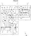
- FIG. 12 is a diagram showing an entire path configuration of the inkjet recording device 400.
- the inkjet recording device 400 includes the device body 1, the print head 2, and the duct 4 connecting the device body 1 and the print head 2.
- the device body 1 includes the main ink container 18 that holds ink 5 circulated.
- the main ink container 18 is connected to a viscosity measuring device 33 through a path 200.
- the viscosity measuring device 33 is connected to a solenoid valve (for supply) 34, which opens/closes a path, through a path 201, and the solenoid valve (for supply) 34 is connected to the pump (for supply) 24, which is used to suck in and pump the ink 5, through paths 202 and 203.
- the pump (for supply) 24 is connected to a filter (for supply) 28, which removes a foreign substance mixed into the ink 5, through a path 204.
- the filter (for supply) 28 is connected to a pressure reducing valve 31, which adjusts the pressure to an appropriate pressure in order to print the ink 5 pumped from the pump (for supply) 24, through a path 205, and the pressure reducing valve 31 is connected to a pressure gauge 32, which measures the pressure of the ink 5 supplied to the nozzles 8A and 8B, through a path 206.
- the pressure gauge 32 is connected to a heater 40 included in the print head 2 through a path 207 passing through the duct 4. The heater 40 performs heating control so that the ink 5 has an appropriate ink temperature when used in a low-temperature environment.
- the heater 40 is connected to a sealing valve 41A, which opens/closes a path, through a path 208A, and the sealing valve 41A is connected to the nozzle 8A through a path 209A.
- the nozzle 8A is provided with an ejection port from which the ink particles 7A are ejected.
- the gutter 14A for catching the ink particles 7A flying straight without being charged and deflected so as not to be used in printing is installed in a straight forward direction of the ejection port of the nozzle 8A.
- the heater 40 is connected to a sealing valve 41B, which opens/closes a path, through a path 208B, and the sealing valve 41B is connected to the nozzle 8B through a path 209B.
- the gutter 14B for catching the ink particles 7B flying straight without being charged and deflected so as not to be used in printing is installed in a straight forward direction of the ejection port of the nozzle 8B.
- printing can be performed by ejecting the ink particles 7A and 7B from the two nozzles 8A and 8B; therefore, it is possible to print larger character(s) or drawing than that printed with one nozzle.
- two nozzles make it possible to print the character(s) or drawing faster than one nozzle does.
- the gutter 14A is connected to a filter (for collection) 30A, which is installed in the device body 1 and removes a foreign substance mixed into ink, through a path 212A passing through the duct 4, and the filter (for collection) 30A is connected to a solenoid valve (for collection) 35A, which opens/closes a path, through a path 213A.
- the solenoid valve (for collection) 35A is connected to the pump (for collection) 25A, which sucks in ink particles 7A caught by the gutter 14A, through a path 214A.
- the pump (for collection) 25A is connected to the main ink container 18 through a path 215A.
- the gutter 14B is connected to a filter (for collection) 30B, which is installed in the device body 1 and removes a foreign substance mixed into ink, through a path 212B passing through the duct 4, and the filter (for collection) 30B is connected to a solenoid valve (for collection) 35B, which opens/closes a path, through a path 213B.
- the solenoid valve (for collection) 35B is connected to the pump (for collection) 25B, which sucks in ink particles 7B caught by the gutter 14B, through a path 214B.
- the pump (for collection) 25B is connected to the main ink container 18 through a path 215B.
- the main ink container 18 is connected to an exhaust air path 217, and the exhaust air path 217 is configured to be communicated with the outside of the device body 1.
- the nozzles 8A and 8B share the common paths 200 to 207 as the ink supply path, and, as the ink collection path, use the separate paths 212A to 215A and 212B to 215B, respectively, and share the common path 217 as the exhaust air path. In this way, only necessary paths are separated, which makes it possible to reduce the size of the device body 1 and to achieve the effects described in the above embodiment.
- the device body 1 includes a spare ink container 19 that holds ink for replenishment, and the spare ink container 19 is connected to a solenoid valve (for replenishment) 36, which opens/closes a path, through a path 221. Then, the solenoid valve (for replenishment) 36 is connected to a merging path 223, which is connected to the ink supply path 203, through a path 222.
- the device body 1 includes a solvent container 20 that holds a solvent for replenishment, and the solvent container 20 is connected to a pump (for solvent) 27, which is used to suck in and pump the solvent, through a path 231.
- the pump (for solvent) 27 is connected to a solenoid valve (for solvent) 38, which opens/closes a flow path, through a path 232, and the solenoid valve (for solvent) 38 is connected to the main ink container 18 through a path 233.
- FIG. 12 the operation of the inkjet recording device 400 is described with FIG. 12 .
- a printing operation i.e., when ink is ejected from the nozzles 8A and 8B.
- the flow rate of ink ejected from the nozzle 8A is about 4 [ml/min].
- the flow rate of ink ejected from the nozzle 8B is about 8 [ml/min].
- the ink 5 ejected from the nozzles 8A and 8B fly in the form of ink particles 7A and 7B and pass through between the charging electrodes 11A and 11B and the deflection electrodes 12A and 12B installed in the print head 2, respectively.
- the pump (for collection) 25A is set to be subject to optimal control to suck about 4 [ml/min] of the ink particles 7A from the gutter 14A; in this case, the flow rate of air sucked out from the gutter 14A is about 150 [ml/min].
- the ink for example, about 4 [ml/min]
- the air for example, about 150 [ml/min]
- the pump (for collection) 25B is set to be subject to optimal control to suck about 8 [ml/min] of the ink particles 7B from the gutter 14B; in this case, the flow rate of air sucked out from the gutter 14B is about 300 [ml/min].
- the air flow rate control range of the pumps (for collection) 25A and 25B is 0 to 500 [ml/min], and the pumps (for collection) 25A and 25B can be controlled to have a different pump flow rate from each other.
- the pumps (for collection) 25A and 25B can be individually subject to optimal pump flow rate control according to the flow rate of ink ejected from the nozzles 8A and 8B, the type of ink 5, the viscosity of the ink 5, the ink supply pressure, the environmental temperature, the internal temperature of the inkjet recording device 400, the height difference between the device body 1 and the print head 2, etc.
- the replacement cycles of the filters are preferably set to the most appropriate time for each filter. If you want the same replacement cycle, the type or the filter medium size of the filters (for collection) 30A and 30B is preferably set to the most appropriate one.
- the ink 5 used in the inkjet recording device 400 is required to dry shortly after printed, and a highly volatile solvent (for example, methyl ethyl ketone, acetone, ethanol, or the like) is used as a solvent of the ink 5.
- a highly volatile solvent for example, methyl ethyl ketone, acetone, ethanol, or the like
- the air flowing through the ink collection paths 212A to 215A and 212B to 215B is mixed with solvent vapor having a concentration close to the saturated vapor concentration.
- the ink 5 (for example, a flow rate of about 12 [ml/min]) collected from the ink collection paths 215A to 215B is stored in the bottom of the main ink container 18, and then, is again fed from the ink supply path 200 to the nozzles 8A and 8B and is reused.
- the air mixed with solvent vapor flowing in from the ink collection paths 215A to 215B (for example, a total flow rate of about 450 [ml/min] because a flow rate of air flowing in from the ink collection path 215A is about 150 [ml/min], and a flow rate of air flowing in from the ink collection path 215B is about 300 [ml/min]) is discharged out of the device from the exhaust air path 217.
- the inkjet recording device 400 when the inkjet recording device 400 is in operation, the air mixed with solvent vapor is discharged out of the device from the exhaust air path 217, and therefore, the ink concentration in the main ink container 18 is high. Accordingly, the solvent is periodically supplied to the main ink container 18, thereby adjusting the concentration of ink supplied to the nozzles 8A and 8B.
- the solenoid valve (for solvent) 38 When the solvent is being supplied, electric current is applied to the solenoid valve (for solvent) 38, and the solenoid valve (for solvent) 38 opens a flow path, and the pump (for solvent) 27 runs, thereby the solvent retained in the solvent container 20 is supplied to the main ink container 18. Reducing the amount of this solvent supplied leads to the reduction of the running cost of the inkjet recording device 400.
- Electric current is applied to the solenoid valve (for collection) 35A, and the solenoid valve (for collection) 35A opens a flow path, and the pump (for collection) 25Aruns, thereby the ink particles 7A caught by the gutter 14A pass through the ink collection paths 212A to 215A and the filter (for collection) 30A and are collected into the main ink container 18 installed in the device body 1. Then, no electric current is applied to the solenoid valve (for collection) 35B, and the solenoid valve (for collection) 35B can close the ink supply paths 213B and 214B, or the pump (for collection) 25B can be at a stop. This can prevent the gutter 14B from sucking in air.
- the nozzles 8A and 8B, the gutters 14A and 14B, etc. may sometimes be cleaned with the solvent for maintenance. After repeating such cleaning, the ink 5 in the main ink container 18 may be diluted. In such a case, when the inkjet recording device 400 is in operation, the flow rate of air in the pumps (for collection) 25A and 25B can be increased, thereby making the ink 5 in the main ink container 18 concentrated.
- the pumps (for collection) 25A and 25B in the present embodiment both allow for a maximum air flow rate of 500 [ml/min]; therefore, the flow rate of the air mixed with solvent vapor discharged out of the device from the exhaust air path 217 is about 1000 [ml/min] with a combination of the two pumps (for collection) 25A and 25B.
- the ink 5 is concentrated while the nozzles 8A and 8B are ejecting the ink 5; however, the ink 5 can also be concentrated by sucking the air from the gutter 14A or 14B in a state in which at least one of the nozzle 8A and the nozzle 8B is not ejecting the ink 5.
- the nozzles 8A and 8B can alternate the ejection of the ink 5 during maintenance on the other nozzle.
- the inkjet recording device 400 including the nozzles 8A and 8B capable of improving the ink collection stability of the gutters 14A and 14B and also reducing the consumption of the solvent when the inkjet recording device 400 is in operation.
- the inkjet recording device 400 including the nozzles 8A and 8B capable of alternating the ink ejection during maintenance on the other nozzle.
- the inkjet recording device 400 including the nozzles 8A and 8B capable of making the ink 5 concentrated by using the pumps (for collection) 25A and 25B when the ink 5 in the main ink container 18 has been diluted because the solvent was used for maintenance.
- the present invention is not limited to the above-described embodiment, and includes various variations. Furthermore, the above embodiment is described in detail to provide a comprehensible explanation about the present invention, and is not always limited to include all the components described above.
- FIG. 1 is a partial cross-sectional view showing an external appearance and an internal configuration of the print head 2 in the present embodiment.
- FIG. 2 is an external perspective view of the print head 2 in the present embodiment.
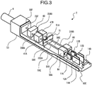
- FIG. 3 is a perspective view of the print head 2 in the present embodiment, where a maintenance cover 70 and a head cover 60 are removed from the print head 2.
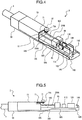
- FIG. 4 is a perspective view of the print head 2 with the head cover 60 removed in the present embodiment.
- FIG. 5 is a partial cross-sectional view of the print head 2 with the head cover 60 removed in the present embodiment.
- FIGS. 6A and 6B are a cross-sectional view and a bottom view of the head cover 60 in the present embodiment, respectively.
- the print head 2 includes nozzles 8A and 8B from which ink 5 is ejected; charging electrodes 11A and 11B that are arranged in parallel and symmetrical about ink beams ejected from the nozzles 8A and 8B, respectively; deflection electrodes 12A and 12B each composed of two electrodes arranged on the secondary side of the charging electrodes 11A and 11B in an ink-beam flying direction; and gutters 14A and 14B with a hole for catching ink particles 7A and 7B not used in printing formed on the same axis as the ink beam.
- the print head 2 further includes sealing valves 41A and 41B for controlling the supply of the ink 5 to the nozzles 8A and 8B through paths 209A and 209B.
- the sealing valves 41A and 41B close a flow path when no electric current is applied to the sealing valves 41A and 41B, and open the flow path when a predetermined electric current is applied to the sealing valves 41A and 41B.
- the sealing valves 41A and 41B are connected to a heater 40 through paths 208A and 208B, respectively.
- the heater 40 is controlled to heat the ink 5 to a predetermined temperature suited for printing (for example, 25 °C) when it is in a low-temperature (for example, 0 °C) environment.
- a path 207 is connected to a pressure gauge 32 in a device body 1 through a duct 4 connected to the print head 2.
- a tube made of Teflon (registered trademark), which is highly resistant to solvents, is used in the paths 209A and 209B, the paths 208A and 208B, and the path 207.
- the nozzles 8A and 8B, the charging electrodes 11A and 11B, the deflection electrodes 12A and 12B, the gutters 14A and 14B, the sealing valves 41A and 41B, and the heater 40 are installed on a base 50G formed on a head base 50.
- each side surface of the head base 50 there are a horizontal uneven side portion 50A that is formed of a thin face extending from near the gutter 14 in parallel with the base 50G, an oblique uneven side portion 50B that is connected to the horizontal uneven side portion 50A and is formed of a thin face cut off in an oblique direction like it is away from the base 50G, and a horizontal uneven side portion 50C that is connected to the oblique uneven side portion 50B and is formed of a thin face parallel with the horizontal uneven side portion 50A.
- the head base 50 further has a vertical uneven end portion 50E formed of a thin face vertical to the base 50G below the gutters 14A and 14B and a back uneven portion 50F between a contact part with the duct 4 and the heater 40.
- the head base 50 still further has a rib 50D formed between the nozzles 8A and 8B and the sealing valves 41A and 41B; the rib 50D extends in a direction vertical to the base 50G.
- a partition member 51 is attached to the rib 50D so as to hold the paths 209A and 209B between the partition member 51 and the rib 50D.
- a dent portion 51A is formed on the upper part of the partition member 51 so as to avoid interference with a proximity sensor 71.
- the maintenance cover 70 is attached to the print head 2 for the purpose of protecting the heater 40 and the sealing valves 41A and 41B.
- the maintenance cover 70 is fixed by being engaged with the back uneven portion 50F, the horizontal uneven side portion 50C, and the partition member 51. Therefore, in a state in which the maintenance cover 70 is attached to the print head 2, the space surrounded by the base 50G on the head base 50 and the maintenance cover 70 is protected from the impact or the like during maintenance. Parts covered with the maintenance cover 70 are the area a serviceman does maintenance.
- the proximity sensor 71 is attached to the maintenance cover 70 so as to be engaged with the dent portion 51A of the partition member 51, and an electric wire 71A for connecting the proximity sensor 71 and the device body 1 is attached to the maintenance cover 70.
- a fixing-screw attachment portion 70A is formed near the partition member 51 on the maintenance cover 70, and a fixing screw 72 is tightened up to fix the head cover 60.
- the head cover 60 is attached to the print head 2 for the purpose of protecting the nozzles 8A and 8B, the charging electrodes 11A and 11B, the deflection electrodes 12A and 12B, and the gutters 14A and 14B.
- a notch portion 60F is formed on the head cover 60 so as to be engaged with the fixing screw 72 of the maintenance cover 70.
- a magnet 61 is attached to the head cover 60 so that the proximity sensor 71 can react when the magnet 61 comes close to the proximity sensor 71 and determine whether the head cover 60 is attached to the proper position.
- the head cover 60 further has a slit 60D through which the ink particles 7A and 7B used in printing pass and a vertical uneven portion 60E formed to cover the gutters 14A and 14B. Then, on each side surface of the head cover 60, a horizontal bottom portion 60A connected in a direction perpendicular to the vertical uneven portion 60E, an oblique bottom portion 60B that is connected to the horizontal bottom portion 60A and is a face parallel with the oblique uneven side portion 50B, and a horizontal bottom portion 60C that is connected to the oblique bottom portion 60B and is a face parallel with the horizontal bottom portion 60A.
- the horizontal uneven side portion 50C is engaged with the horizontal bottom portion 60C
- the horizontal uneven side portion 50A is engaged with the horizontal bottom portion 60A
- the vertical uneven end portion 50E is engaged with the vertical uneven portion 60E.
- FIGS. 8A to 8D The operation of the inkjet recording device 400 according to Embodiment 2 when fixing the head cover 60 to the print head 2 is described with FIGS. 8A to 8D .
- Moving the head cover 60 in a horizontal direction facilitates the attachment and removal of parts during maintenance of the print head 2.
- FIG. 8A shows a state in which the magnet 61 attached to the head cover 60 is located on top of the nozzle 8A.
- the print head 2 is in a state in which the horizontal uneven side portion 50A is in contact with the horizontal bottom portion 60C, and, when the head cover 60 is fixed to the print head 2, by moving the position of the magnet 61 upward, the magnet 61 is prevented from colliding with the nozzle 8A.
- FIG. 8B shows a state in which the head cover 60 is moved to a direction of the maintenance cover 70 than that in FIG. 8A .
- the magnet 61 has already passed the top of the nozzle 8A, and there is no obstacle below the magnet 61.
- FIG. 8C shows a state of the print head 2 in which the head cover 60 is further moved to the direction of the maintenance cover 70 than that in FIG. 8B .
- the horizontal uneven side portion 50C is in contact with the horizontal bottom portion 60C
- the oblique uneven side portion 50B is in contact with the oblique bottom portion 60B
- the horizontal uneven side portion 50A is in contact with the horizontal bottom portion 60A
- the vertical uneven end portion 50E is in contact with the vertical uneven portion 60E.
- the head cover 60 is further moved downward than that in FIG. 8B , and is on the same level as when fixed.
- FIG. 8D shows a state of the print head 2 in which the head cover 60 is fixed.
- the head cover 60 is fixed with the fixing screw 72 in a state in which the head cover 60 is in contact with the maintenance cover 70. Furthermore, the magnet 61 comes close to the reaction distance of the proximity sensor 71. Therefore, the inkjet recording device 400 can detect that the head cover 60 is fixed to the print head 2.
- the present embodiment it is possible to prevent the installed parts from colliding with each other when the head cover 60 is attached to or removed from the print head 2; therefore, it is possible to improve the maintainability. Furthermore, it is only necessary to adopt the structure in which the installed parts are prevented from colliding with each other in a state in which the head cover 60 is attached to the print head 2; therefore, it is possible to provide the inkjet recording device 400 including the compact print head 2 as compared with a case in which the configuration in the present invention is not used.
- the present invention is not limited to the above-described embodiment, and includes various variations. Furthermore, the above embodiment is described in detail to provide a comprehensible explanation about the present invention, and is not always limited to ones including all the components described above.
Landscapes
- Particle Formation And Scattering Control In Inkjet Printers (AREA)
- Ink Jet (AREA)
Claims (11)
- Eine Tintenstrahlaufzeichnungsvorrichtung (400), umfassend:einen Tintenbehälter (18), der Tinte (5) enthält, die zum Drucken auf einen bedruckten Gegenstand (13) verwendet wird;eine Vielzahl von Düsen (8A, 8B), die mit dem Tintenbehälter (18) verbunden sind und aus denen die Tinte (5) ausgestoßen wird;einen verzweigten Pfad, der von dem Tintenbehälter (18) zu der Vielzahl von Düsen (8A, 8B) führt;ein Durchflussregelventil, das an einem Rohr installiert ist, das von dem verzweigten Pfad zu der Vielzahl von Düsen führt;eine Mehrzahl von Rinnen (14A, 14B), die die beim Drucken nicht genutzte Tinte (5) sammeln;eine Mehrzahl von Tintensammelpfaden (212A bis 215A, 212B bis 215B), die mit der Mehrzahl von Rinnen (14A, 14B) verbunden sind; undeine Mehrzahl von Tintensammelpumpen (25A, 25B), die mit der Vielzahl von Tintensammelpfaden (212A bis 215A, 212B bis 215B) verbunden sind, dadurch gekennzeichnet, dass sie ferner umfasst:
einen einzigen Abluftweg (217) für Lösungsmitteldampf, der mit dem Tintenbehälter (18) verbunden ist. - Eine Tintenstrahlaufzeichnungsvorrichtung (400) nach Anspruch 1, ferner umfassend:einen einzelnen Tintenzufuhrpfad (200), der mit dem Tintenbehälter (18) verbunden ist; undeine einzelne Tintenversorgungspumpe (24), die an den Tintenversorgungsweg (200) angeschlossen ist.
- Eine Tintenstrahlaufzeichnungsvorrichtung (400) nach einem der Ansprüche 1 bis 2, wobei
die Mehrzahl von Tintensammelpumpen (25A, 25B) in der Lage ist, den Betrieb jeder der Tintensammelpumpen (25A, 25B) individuell zu steuern. - Eine Tintenstrahlaufzeichnungsvorrichtung (400) nach einem der Ansprüche 1 bis 3, wobei
mindestens eine der mehreren Tintensammelpumpen (25A, 25B) in der Lage ist, einen Druckvorgang fortzusetzen, während ein Ausstoß der Tinte (5) gestoppt wird. - Eine Tintenstrahlaufzeichnungsvorrichtung (400) nach Anspruch 4, wobei
mindestens einer der Vielzahl von Tintensammelpfaden (212A bis 215A, 212B bis 215B) in der Lage ist, einen Fluss der Tinte (5) an einer Düsenseite zu stoppen, so dass der Ausstoß der Tinte (5) gestoppt wird. - Eine Tintenstrahlaufzeichnungsvorrichtung (400) nach Anspruch 4 oder 5, wobei mindestens einer der mehreren Tintensammelpfade (212A bis 215A, 212B bis 215B) in der Lage ist, ein Gas anzusaugen, indem er die mehreren Tintensammelpumpen (25A, 25B) laufen lässt, während er einen Fluss der Tinte (5) an einer Düsenseite stoppt, so dass der Ausstoß der Tinte (5) gestoppt wird.
- Eine Tintenstrahlaufzeichnungsvorrichtung (400) nach einem der Ansprüche 1 bis 6, wobei
die Tinte (5) durch Absaugen eines Gases aus der Vielzahl der Rinnen (14A, 14B) konzentriert werden kann. - Eine Tintenstrahlaufzeichnungsvorrichtung (400) nach einem der Ansprüche 1 bis 7, wobei
ein Lochdurchmesser eines Tintenausstoßes für mindestens eine der Vielzahl von Düsen (8A, 8B) sich von einem Lochdurchmesser eines Tintenausstoßes für die anderen Düsen (8A, 8B) unterscheidet. - Eine Tintenstrahlaufzeichnungsvorrichtung (400) nach einem der Ansprüche 1 bis 8, ferner umfassend:
verschiedene Arten von Sammelfiltern (30A, 30B), die mit der Vielzahl von Tintensammelpfaden (212A bis 215A, 212B bis 215B) verbunden sind. - Eine Tintenstrahlaufzeichnungsvorrichtung (400) nach einem der Ansprüche 1 bis 9, ferner umfassend:
Sammelfilter (30A, 30B) mit verschiedenen Austauschzyklen, die mit der Vielzahl von Tintensammelpfaden (212A bis 215A, 212B bis 215B) verbunden sind. - Eine Tintenstrahlaufzeichnungsvorrichtung (400) nach einem der Ansprüche 1 bis 10, wobei
der verzweigte Pfad im Druckkopf (2) angeordnet ist.
Applications Claiming Priority (2)
| Application Number | Priority Date | Filing Date | Title |
|---|---|---|---|
| JP2016161623A JP6626801B2 (ja) | 2016-08-22 | 2016-08-22 | インクジェット記録装置 |
| EP17187243.5A EP3287287B1 (de) | 2016-08-22 | 2017-08-22 | Tintenstrahlaufzeichnungsvorrichtung |
Related Parent Applications (2)
| Application Number | Title | Priority Date | Filing Date |
|---|---|---|---|
| EP17187243.5A Division-Into EP3287287B1 (de) | 2016-08-22 | 2017-08-22 | Tintenstrahlaufzeichnungsvorrichtung |
| EP17187243.5A Division EP3287287B1 (de) | 2016-08-22 | 2017-08-22 | Tintenstrahlaufzeichnungsvorrichtung |
Publications (3)
| Publication Number | Publication Date |
|---|---|
| EP3431297A2 EP3431297A2 (de) | 2019-01-23 |
| EP3431297A3 EP3431297A3 (de) | 2019-04-24 |
| EP3431297B1 true EP3431297B1 (de) | 2020-06-17 |
Family
ID=59683480
Family Applications (2)
| Application Number | Title | Priority Date | Filing Date |
|---|---|---|---|
| EP18185934.9A Active EP3431297B1 (de) | 2016-08-22 | 2017-08-22 | Tintenstrahlaufzeichnungsvorrichtung |
| EP17187243.5A Active EP3287287B1 (de) | 2016-08-22 | 2017-08-22 | Tintenstrahlaufzeichnungsvorrichtung |
Family Applications After (1)
| Application Number | Title | Priority Date | Filing Date |
|---|---|---|---|
| EP17187243.5A Active EP3287287B1 (de) | 2016-08-22 | 2017-08-22 | Tintenstrahlaufzeichnungsvorrichtung |
Country Status (3)
| Country | Link |
|---|---|
| US (1) | US10857787B2 (de) |
| EP (2) | EP3431297B1 (de) |
| JP (1) | JP6626801B2 (de) |
Families Citing this family (2)
| Publication number | Priority date | Publication date | Assignee | Title |
|---|---|---|---|---|
| US20210001555A1 (en) * | 2019-07-02 | 2021-01-07 | 3D Systems, Inc. | Three-Dimensional Printing System with High Capacity Servicing Module |
| GB202204762D0 (en) * | 2022-04-01 | 2022-05-18 | Ricoh Co Ltd | Ink delivery system |
Family Cites Families (18)
| Publication number | Priority date | Publication date | Assignee | Title |
|---|---|---|---|---|
| US4303924A (en) * | 1978-12-26 | 1981-12-01 | The Mead Corporation | Jet drop printing process utilizing a radiation curable ink |
| JPS63125346A (ja) * | 1986-11-14 | 1988-05-28 | Ricoh Co Ltd | インクジエツト印字装置のヘツドモジユ−ル |
| GB2259276B (en) * | 1991-09-06 | 1995-09-27 | Linx Printing Tech | Ink jet printer |
| US6499823B2 (en) * | 2000-06-15 | 2002-12-31 | Canon Kabushiki Kaisha | Ink jet recording head having substrate and ceiling plate base pressed together by base plate and ink supply member |
| JP4604613B2 (ja) * | 2004-09-08 | 2011-01-05 | ブラザー工業株式会社 | インクジェットプリンタヘッド |
| JP4810293B2 (ja) * | 2006-04-28 | 2011-11-09 | キヤノン株式会社 | 吸引方法及びインクジェット記録装置 |
| GB0719992D0 (en) * | 2007-10-12 | 2007-11-21 | Videojet Technologies Inc | Ink jet printer head assembly |
| US20090167795A1 (en) * | 2007-12-27 | 2009-07-02 | Seiko Epson Corporation | Liquid supply unit, liquid ejecting apparatus, and liquid supplying method |
| CN101497265B (zh) * | 2008-01-28 | 2011-08-31 | 株式会社日立产机系统 | 喷墨记录装置 |
| DE102008055999B3 (de) * | 2008-11-05 | 2010-03-11 | Kba-Metronic Aktiengesellschaft | Druckkopf mit integrierten Ablenkelektroden |
| JP2010131917A (ja) * | 2008-12-05 | 2010-06-17 | Hitachi Industrial Equipment Systems Co Ltd | インクジェット記録装置 |
| IN2012DN00864A (de) * | 2009-08-11 | 2015-07-10 | Hitachi Ind Equipment Sys | |
| JP5328630B2 (ja) * | 2009-12-18 | 2013-10-30 | キヤノン株式会社 | インクジェット記録装置および予備吐出発数の決定方法 |
| JP2012066422A (ja) * | 2010-09-22 | 2012-04-05 | Hitachi Industrial Equipment Systems Co Ltd | インクジェット記録装置 |
| WO2013173200A1 (en) * | 2012-05-14 | 2013-11-21 | Videojet Technologies Inc. | Ink jet printer |
| JP5956279B2 (ja) * | 2012-08-08 | 2016-07-27 | 株式会社日立産機システム | 気液分離器、及びそれを備えたインクジェット記録装置 |
| JP6338861B2 (ja) * | 2014-01-08 | 2018-06-06 | 株式会社日立産機システム | インクジェット記録装置 |
| CN105584218A (zh) * | 2016-02-01 | 2016-05-18 | 厦门英杰华机电科技有限公司 | 平行双嘴cij喷码系统 |
-
2016
- 2016-08-22 JP JP2016161623A patent/JP6626801B2/ja active Active
-
2017
- 2017-08-21 US US15/681,711 patent/US10857787B2/en active Active
- 2017-08-22 EP EP18185934.9A patent/EP3431297B1/de active Active
- 2017-08-22 EP EP17187243.5A patent/EP3287287B1/de active Active
Non-Patent Citations (1)
| Title |
|---|
| None * |
Also Published As
| Publication number | Publication date |
|---|---|
| EP3287287B1 (de) | 2020-04-01 |
| EP3431297A3 (de) | 2019-04-24 |
| EP3431297A2 (de) | 2019-01-23 |
| EP3287287A3 (de) | 2018-08-29 |
| US10857787B2 (en) | 2020-12-08 |
| EP3287287A2 (de) | 2018-02-28 |
| US20180050535A1 (en) | 2018-02-22 |
| JP6626801B2 (ja) | 2019-12-25 |
| JP2018030232A (ja) | 2018-03-01 |
Similar Documents
| Publication | Publication Date | Title |
|---|---|---|
| JP7413459B2 (ja) | 洗浄装置、及びインクジェット記録装置 | |
| JP7675784B2 (ja) | インクジェット記録装置 | |
| US8672449B2 (en) | Inkjet recording apparatus | |
| JP5956279B2 (ja) | 気液分離器、及びそれを備えたインクジェット記録装置 | |
| US20150231889A1 (en) | Liquid Container Coupled to a Refill Container and Ink-Jet Recording Apparatus Having Same | |
| EP3287287B1 (de) | Tintenstrahlaufzeichnungsvorrichtung | |
| US20080111851A1 (en) | Printing Mechanism with Ink Spray Suction | |
| JPH05208502A (ja) | インクジェットプリンタのための印刷ヘッドとインクジェット印刷の方法 | |
| US8459775B2 (en) | Liquid ejecting head, liquid ejecting head unit and liquid ejecting apparatus | |
| US20200276823A1 (en) | Pigment dispersal in an ink jet printer | |
| JP2011067775A (ja) | インクジェット記録装置 | |
| CN103459157B (zh) | 用于连续喷墨打印机中的激发范围检测的新方法 | |
| EP3587122B1 (de) | Druckkopf für einen tintenstrahldrucker mit zwei rinnen zur rückgewinnung, von denen eine beweglich ist | |
| JP6401815B2 (ja) | 気液分離器、及びそれを備えたインクジェット記録装置 | |
| EP3587124B1 (de) | Verfahren und vorrichtung zur erkennung des korrekten betriebs der düsen eines druckkopfes | |
| JP2014065203A (ja) | インクジェット記録装置 | |
| US20220363054A1 (en) | Inkjet Printer | |
| US20110085001A1 (en) | Ejection Examination Apparatus and Printing Apparatus | |
| US20110084998A1 (en) | Discharge Inspection Apparatus and Discharge Inspection Method | |
| JP7066859B2 (ja) | インクジェット記録装置 | |
| JP5379778B2 (ja) | インクジェット記録装置 | |
| JP2013184361A (ja) | 液体吐出装置、及び、液体の置換方法 | |
| EP3840955B1 (de) | Gemeinsame rinnenmessung | |
| JP2012206385A (ja) | インクジェット記録装置 | |
| JP7233897B2 (ja) | インクジェット記録装置 |
Legal Events
| Date | Code | Title | Description |
|---|---|---|---|
| PUAI | Public reference made under article 153(3) epc to a published international application that has entered the european phase |
Free format text: ORIGINAL CODE: 0009012 |
|
| STAA | Information on the status of an ep patent application or granted ep patent |
Free format text: STATUS: REQUEST FOR EXAMINATION WAS MADE |
|
| 17P | Request for examination filed |
Effective date: 20180727 |
|
| AC | Divisional application: reference to earlier application |
Ref document number: 3287287 Country of ref document: EP Kind code of ref document: P |
|
| AK | Designated contracting states |
Kind code of ref document: A2 Designated state(s): AL AT BE BG CH CY CZ DE DK EE ES FI FR GB GR HR HU IE IS IT LI LT LU LV MC MK MT NL NO PL PT RO RS SE SI SK SM TR |
|
| AX | Request for extension of the european patent |
Extension state: BA ME |
|
| PUAL | Search report despatched |
Free format text: ORIGINAL CODE: 0009013 |
|
| AK | Designated contracting states |
Kind code of ref document: A3 Designated state(s): AL AT BE BG CH CY CZ DE DK EE ES FI FR GB GR HR HU IE IS IT LI LT LU LV MC MK MT NL NO PL PT RO RS SE SI SK SM TR |
|
| AX | Request for extension of the european patent |
Extension state: BA ME |
|
| RIC1 | Information provided on ipc code assigned before grant |
Ipc: B41J 2/185 20060101AFI20190319BHEP Ipc: B41J 2/08 20060101ALI20190319BHEP |
|
| GRAP | Despatch of communication of intention to grant a patent |
Free format text: ORIGINAL CODE: EPIDOSNIGR1 |
|
| STAA | Information on the status of an ep patent application or granted ep patent |
Free format text: STATUS: GRANT OF PATENT IS INTENDED |
|
| INTG | Intention to grant announced |
Effective date: 20200303 |
|
| GRAS | Grant fee paid |
Free format text: ORIGINAL CODE: EPIDOSNIGR3 |
|
| GRAA | (expected) grant |
Free format text: ORIGINAL CODE: 0009210 |
|
| STAA | Information on the status of an ep patent application or granted ep patent |
Free format text: STATUS: THE PATENT HAS BEEN GRANTED |
|
| AC | Divisional application: reference to earlier application |
Ref document number: 3287287 Country of ref document: EP Kind code of ref document: P |
|
| AK | Designated contracting states |
Kind code of ref document: B1 Designated state(s): AL AT BE BG CH CY CZ DE DK EE ES FI FR GB GR HR HU IE IS IT LI LT LU LV MC MK MT NL NO PL PT RO RS SE SI SK SM TR |
|
| REG | Reference to a national code |
Ref country code: GB Ref legal event code: FG4D |
|
| REG | Reference to a national code |
Ref country code: CH Ref legal event code: EP |
|
| REG | Reference to a national code |
Ref country code: IE Ref legal event code: FG4D |
|
| REG | Reference to a national code |
Ref country code: AT Ref legal event code: REF Ref document number: 1280839 Country of ref document: AT Kind code of ref document: T Effective date: 20200715 |
|
| REG | Reference to a national code |
Ref country code: DE Ref legal event code: R096 Ref document number: 602017018517 Country of ref document: DE |
|
| PG25 | Lapsed in a contracting state [announced via postgrant information from national office to epo] |
Ref country code: SE Free format text: LAPSE BECAUSE OF FAILURE TO SUBMIT A TRANSLATION OF THE DESCRIPTION OR TO PAY THE FEE WITHIN THE PRESCRIBED TIME-LIMIT Effective date: 20200617 Ref country code: LT Free format text: LAPSE BECAUSE OF FAILURE TO SUBMIT A TRANSLATION OF THE DESCRIPTION OR TO PAY THE FEE WITHIN THE PRESCRIBED TIME-LIMIT Effective date: 20200617 Ref country code: FI Free format text: LAPSE BECAUSE OF FAILURE TO SUBMIT A TRANSLATION OF THE DESCRIPTION OR TO PAY THE FEE WITHIN THE PRESCRIBED TIME-LIMIT Effective date: 20200617 Ref country code: GR Free format text: LAPSE BECAUSE OF FAILURE TO SUBMIT A TRANSLATION OF THE DESCRIPTION OR TO PAY THE FEE WITHIN THE PRESCRIBED TIME-LIMIT Effective date: 20200918 Ref country code: NO Free format text: LAPSE BECAUSE OF FAILURE TO SUBMIT A TRANSLATION OF THE DESCRIPTION OR TO PAY THE FEE WITHIN THE PRESCRIBED TIME-LIMIT Effective date: 20200917 |
|
| REG | Reference to a national code |
Ref country code: LT Ref legal event code: MG4D |
|
| REG | Reference to a national code |
Ref country code: NL Ref legal event code: MP Effective date: 20200617 |
|
| PG25 | Lapsed in a contracting state [announced via postgrant information from national office to epo] |
Ref country code: LV Free format text: LAPSE BECAUSE OF FAILURE TO SUBMIT A TRANSLATION OF THE DESCRIPTION OR TO PAY THE FEE WITHIN THE PRESCRIBED TIME-LIMIT Effective date: 20200617 Ref country code: HR Free format text: LAPSE BECAUSE OF FAILURE TO SUBMIT A TRANSLATION OF THE DESCRIPTION OR TO PAY THE FEE WITHIN THE PRESCRIBED TIME-LIMIT Effective date: 20200617 Ref country code: RS Free format text: LAPSE BECAUSE OF FAILURE TO SUBMIT A TRANSLATION OF THE DESCRIPTION OR TO PAY THE FEE WITHIN THE PRESCRIBED TIME-LIMIT Effective date: 20200617 Ref country code: BG Free format text: LAPSE BECAUSE OF FAILURE TO SUBMIT A TRANSLATION OF THE DESCRIPTION OR TO PAY THE FEE WITHIN THE PRESCRIBED TIME-LIMIT Effective date: 20200917 |
|
| REG | Reference to a national code |
Ref country code: AT Ref legal event code: MK05 Ref document number: 1280839 Country of ref document: AT Kind code of ref document: T Effective date: 20200617 |
|
| PG25 | Lapsed in a contracting state [announced via postgrant information from national office to epo] |
Ref country code: NL Free format text: LAPSE BECAUSE OF FAILURE TO SUBMIT A TRANSLATION OF THE DESCRIPTION OR TO PAY THE FEE WITHIN THE PRESCRIBED TIME-LIMIT Effective date: 20200617 Ref country code: AL Free format text: LAPSE BECAUSE OF FAILURE TO SUBMIT A TRANSLATION OF THE DESCRIPTION OR TO PAY THE FEE WITHIN THE PRESCRIBED TIME-LIMIT Effective date: 20200617 |
|
| PG25 | Lapsed in a contracting state [announced via postgrant information from national office to epo] |
Ref country code: RO Free format text: LAPSE BECAUSE OF FAILURE TO SUBMIT A TRANSLATION OF THE DESCRIPTION OR TO PAY THE FEE WITHIN THE PRESCRIBED TIME-LIMIT Effective date: 20200617 Ref country code: CZ Free format text: LAPSE BECAUSE OF FAILURE TO SUBMIT A TRANSLATION OF THE DESCRIPTION OR TO PAY THE FEE WITHIN THE PRESCRIBED TIME-LIMIT Effective date: 20200617 Ref country code: PT Free format text: LAPSE BECAUSE OF FAILURE TO SUBMIT A TRANSLATION OF THE DESCRIPTION OR TO PAY THE FEE WITHIN THE PRESCRIBED TIME-LIMIT Effective date: 20201019 Ref country code: ES Free format text: LAPSE BECAUSE OF FAILURE TO SUBMIT A TRANSLATION OF THE DESCRIPTION OR TO PAY THE FEE WITHIN THE PRESCRIBED TIME-LIMIT Effective date: 20200617 Ref country code: AT Free format text: LAPSE BECAUSE OF FAILURE TO SUBMIT A TRANSLATION OF THE DESCRIPTION OR TO PAY THE FEE WITHIN THE PRESCRIBED TIME-LIMIT Effective date: 20200617 Ref country code: IT Free format text: LAPSE BECAUSE OF FAILURE TO SUBMIT A TRANSLATION OF THE DESCRIPTION OR TO PAY THE FEE WITHIN THE PRESCRIBED TIME-LIMIT Effective date: 20200617 Ref country code: EE Free format text: LAPSE BECAUSE OF FAILURE TO SUBMIT A TRANSLATION OF THE DESCRIPTION OR TO PAY THE FEE WITHIN THE PRESCRIBED TIME-LIMIT Effective date: 20200617 Ref country code: SM Free format text: LAPSE BECAUSE OF FAILURE TO SUBMIT A TRANSLATION OF THE DESCRIPTION OR TO PAY THE FEE WITHIN THE PRESCRIBED TIME-LIMIT Effective date: 20200617 |
|
| PG25 | Lapsed in a contracting state [announced via postgrant information from national office to epo] |
Ref country code: PL Free format text: LAPSE BECAUSE OF FAILURE TO SUBMIT A TRANSLATION OF THE DESCRIPTION OR TO PAY THE FEE WITHIN THE PRESCRIBED TIME-LIMIT Effective date: 20200617 Ref country code: SK Free format text: LAPSE BECAUSE OF FAILURE TO SUBMIT A TRANSLATION OF THE DESCRIPTION OR TO PAY THE FEE WITHIN THE PRESCRIBED TIME-LIMIT Effective date: 20200617 Ref country code: IS Free format text: LAPSE BECAUSE OF FAILURE TO SUBMIT A TRANSLATION OF THE DESCRIPTION OR TO PAY THE FEE WITHIN THE PRESCRIBED TIME-LIMIT Effective date: 20201017 |
|
| REG | Reference to a national code |
Ref country code: DE Ref legal event code: R097 Ref document number: 602017018517 Country of ref document: DE |
|
| PG25 | Lapsed in a contracting state [announced via postgrant information from national office to epo] |
Ref country code: MC Free format text: LAPSE BECAUSE OF FAILURE TO SUBMIT A TRANSLATION OF THE DESCRIPTION OR TO PAY THE FEE WITHIN THE PRESCRIBED TIME-LIMIT Effective date: 20200617 |
|
| REG | Reference to a national code |
Ref country code: CH Ref legal event code: PL |
|
| PLBE | No opposition filed within time limit |
Free format text: ORIGINAL CODE: 0009261 |
|
| STAA | Information on the status of an ep patent application or granted ep patent |
Free format text: STATUS: NO OPPOSITION FILED WITHIN TIME LIMIT |
|
| PG25 | Lapsed in a contracting state [announced via postgrant information from national office to epo] |
Ref country code: DK Free format text: LAPSE BECAUSE OF FAILURE TO SUBMIT A TRANSLATION OF THE DESCRIPTION OR TO PAY THE FEE WITHIN THE PRESCRIBED TIME-LIMIT Effective date: 20200617 Ref country code: CH Free format text: LAPSE BECAUSE OF NON-PAYMENT OF DUE FEES Effective date: 20200831 Ref country code: LI Free format text: LAPSE BECAUSE OF NON-PAYMENT OF DUE FEES Effective date: 20200831 Ref country code: LU Free format text: LAPSE BECAUSE OF NON-PAYMENT OF DUE FEES Effective date: 20200822 |
|
| 26N | No opposition filed |
Effective date: 20210318 |
|
| REG | Reference to a national code |
Ref country code: BE Ref legal event code: MM Effective date: 20200831 |
|
| PG25 | Lapsed in a contracting state [announced via postgrant information from national office to epo] |
Ref country code: SI Free format text: LAPSE BECAUSE OF FAILURE TO SUBMIT A TRANSLATION OF THE DESCRIPTION OR TO PAY THE FEE WITHIN THE PRESCRIBED TIME-LIMIT Effective date: 20200617 |
|
| PG25 | Lapsed in a contracting state [announced via postgrant information from national office to epo] |
Ref country code: IE Free format text: LAPSE BECAUSE OF NON-PAYMENT OF DUE FEES Effective date: 20200822 Ref country code: BE Free format text: LAPSE BECAUSE OF NON-PAYMENT OF DUE FEES Effective date: 20200831 |
|
| PG25 | Lapsed in a contracting state [announced via postgrant information from national office to epo] |
Ref country code: TR Free format text: LAPSE BECAUSE OF FAILURE TO SUBMIT A TRANSLATION OF THE DESCRIPTION OR TO PAY THE FEE WITHIN THE PRESCRIBED TIME-LIMIT Effective date: 20200617 Ref country code: MT Free format text: LAPSE BECAUSE OF FAILURE TO SUBMIT A TRANSLATION OF THE DESCRIPTION OR TO PAY THE FEE WITHIN THE PRESCRIBED TIME-LIMIT Effective date: 20200617 Ref country code: CY Free format text: LAPSE BECAUSE OF FAILURE TO SUBMIT A TRANSLATION OF THE DESCRIPTION OR TO PAY THE FEE WITHIN THE PRESCRIBED TIME-LIMIT Effective date: 20200617 |
|
| PG25 | Lapsed in a contracting state [announced via postgrant information from national office to epo] |
Ref country code: MK Free format text: LAPSE BECAUSE OF FAILURE TO SUBMIT A TRANSLATION OF THE DESCRIPTION OR TO PAY THE FEE WITHIN THE PRESCRIBED TIME-LIMIT Effective date: 20200617 |
|
| PGFP | Annual fee paid to national office [announced via postgrant information from national office to epo] |
Ref country code: DE Payment date: 20250702 Year of fee payment: 9 |
|
| PGFP | Annual fee paid to national office [announced via postgrant information from national office to epo] |
Ref country code: GB Payment date: 20250703 Year of fee payment: 9 |
|
| PGFP | Annual fee paid to national office [announced via postgrant information from national office to epo] |
Ref country code: FR Payment date: 20250703 Year of fee payment: 9 |