EP3429544B1 - Verfahren zur herstellung einer medizinischen zubereitung unter verwendung einer schlauchpumpe - Google Patents
Verfahren zur herstellung einer medizinischen zubereitung unter verwendung einer schlauchpumpe Download PDFInfo
- Publication number
- EP3429544B1 EP3429544B1 EP17710303.3A EP17710303A EP3429544B1 EP 3429544 B1 EP3429544 B1 EP 3429544B1 EP 17710303 A EP17710303 A EP 17710303A EP 3429544 B1 EP3429544 B1 EP 3429544B1
- Authority
- EP
- European Patent Office
- Prior art keywords
- liquid
- producing
- target container
- pump
- medical preparation
- Prior art date
- Legal status (The legal status is an assumption and is not a legal conclusion. Google has not performed a legal analysis and makes no representation as to the accuracy of the status listed.)
- Active
Links
Images


Classifications
-
- A—HUMAN NECESSITIES
- A61—MEDICAL OR VETERINARY SCIENCE; HYGIENE
- A61J—CONTAINERS SPECIALLY ADAPTED FOR MEDICAL OR PHARMACEUTICAL PURPOSES; DEVICES OR METHODS SPECIALLY ADAPTED FOR BRINGING PHARMACEUTICAL PRODUCTS INTO PARTICULAR PHYSICAL OR ADMINISTERING FORMS; DEVICES FOR ADMINISTERING FOOD OR MEDICINES ORALLY; BABY COMFORTERS; DEVICES FOR RECEIVING SPITTLE
- A61J3/00—Devices or methods specially adapted for bringing pharmaceutical products into particular physical or administering forms
- A61J3/002—Compounding apparatus specially for enteral or parenteral nutritive solutions
-
- A—HUMAN NECESSITIES
- A61—MEDICAL OR VETERINARY SCIENCE; HYGIENE
- A61M—DEVICES FOR INTRODUCING MEDIA INTO, OR ONTO, THE BODY; DEVICES FOR TRANSDUCING BODY MEDIA OR FOR TAKING MEDIA FROM THE BODY; DEVICES FOR PRODUCING OR ENDING SLEEP OR STUPOR
- A61M1/00—Suction or pumping devices for medical purposes; Devices for carrying-off, for treatment of, or for carrying-over, body-liquids; Drainage systems
- A61M1/14—Dialysis systems; Artificial kidneys; Blood oxygenators ; Reciprocating systems for treatment of body fluids, e.g. single needle systems for hemofiltration or pheresis
- A61M1/16—Dialysis systems; Artificial kidneys; Blood oxygenators ; Reciprocating systems for treatment of body fluids, e.g. single needle systems for hemofiltration or pheresis with membranes
- A61M1/1621—Constructional aspects thereof
- A61M1/1645—Constructional aspects thereof with mechanically linked peristaltic dialysis fluid pumps one upstream, the other one downstream of the dialyser
-
- A—HUMAN NECESSITIES
- A61—MEDICAL OR VETERINARY SCIENCE; HYGIENE
- A61M—DEVICES FOR INTRODUCING MEDIA INTO, OR ONTO, THE BODY; DEVICES FOR TRANSDUCING BODY MEDIA OR FOR TAKING MEDIA FROM THE BODY; DEVICES FOR PRODUCING OR ENDING SLEEP OR STUPOR
- A61M1/00—Suction or pumping devices for medical purposes; Devices for carrying-off, for treatment of, or for carrying-over, body-liquids; Drainage systems
- A61M1/14—Dialysis systems; Artificial kidneys; Blood oxygenators ; Reciprocating systems for treatment of body fluids, e.g. single needle systems for hemofiltration or pheresis
- A61M1/16—Dialysis systems; Artificial kidneys; Blood oxygenators ; Reciprocating systems for treatment of body fluids, e.g. single needle systems for hemofiltration or pheresis with membranes
- A61M1/1654—Dialysates therefor
- A61M1/1656—Apparatus for preparing dialysates
- A61M1/1668—Details of containers
-
- A—HUMAN NECESSITIES
- A61—MEDICAL OR VETERINARY SCIENCE; HYGIENE
- A61M—DEVICES FOR INTRODUCING MEDIA INTO, OR ONTO, THE BODY; DEVICES FOR TRANSDUCING BODY MEDIA OR FOR TAKING MEDIA FROM THE BODY; DEVICES FOR PRODUCING OR ENDING SLEEP OR STUPOR
- A61M1/00—Suction or pumping devices for medical purposes; Devices for carrying-off, for treatment of, or for carrying-over, body-liquids; Drainage systems
- A61M1/14—Dialysis systems; Artificial kidneys; Blood oxygenators ; Reciprocating systems for treatment of body fluids, e.g. single needle systems for hemofiltration or pheresis
- A61M1/16—Dialysis systems; Artificial kidneys; Blood oxygenators ; Reciprocating systems for treatment of body fluids, e.g. single needle systems for hemofiltration or pheresis with membranes
- A61M1/26—Dialysis systems; Artificial kidneys; Blood oxygenators ; Reciprocating systems for treatment of body fluids, e.g. single needle systems for hemofiltration or pheresis with membranes and internal elements which are moving
- A61M1/262—Dialysis systems; Artificial kidneys; Blood oxygenators ; Reciprocating systems for treatment of body fluids, e.g. single needle systems for hemofiltration or pheresis with membranes and internal elements which are moving rotating
-
- A—HUMAN NECESSITIES
- A61—MEDICAL OR VETERINARY SCIENCE; HYGIENE
- A61M—DEVICES FOR INTRODUCING MEDIA INTO, OR ONTO, THE BODY; DEVICES FOR TRANSDUCING BODY MEDIA OR FOR TAKING MEDIA FROM THE BODY; DEVICES FOR PRODUCING OR ENDING SLEEP OR STUPOR
- A61M1/00—Suction or pumping devices for medical purposes; Devices for carrying-off, for treatment of, or for carrying-over, body-liquids; Drainage systems
- A61M1/14—Dialysis systems; Artificial kidneys; Blood oxygenators ; Reciprocating systems for treatment of body fluids, e.g. single needle systems for hemofiltration or pheresis
- A61M1/16—Dialysis systems; Artificial kidneys; Blood oxygenators ; Reciprocating systems for treatment of body fluids, e.g. single needle systems for hemofiltration or pheresis with membranes
- A61M1/26—Dialysis systems; Artificial kidneys; Blood oxygenators ; Reciprocating systems for treatment of body fluids, e.g. single needle systems for hemofiltration or pheresis with membranes and internal elements which are moving
- A61M1/267—Dialysis systems; Artificial kidneys; Blood oxygenators ; Reciprocating systems for treatment of body fluids, e.g. single needle systems for hemofiltration or pheresis with membranes and internal elements which are moving used for pumping
-
- A—HUMAN NECESSITIES
- A61—MEDICAL OR VETERINARY SCIENCE; HYGIENE
- A61M—DEVICES FOR INTRODUCING MEDIA INTO, OR ONTO, THE BODY; DEVICES FOR TRANSDUCING BODY MEDIA OR FOR TAKING MEDIA FROM THE BODY; DEVICES FOR PRODUCING OR ENDING SLEEP OR STUPOR
- A61M1/00—Suction or pumping devices for medical purposes; Devices for carrying-off, for treatment of, or for carrying-over, body-liquids; Drainage systems
- A61M1/36—Other treatment of blood in a by-pass of the natural circulatory system, e.g. temperature adaptation, irradiation ; Extra-corporeal blood circuits
- A61M1/3621—Extra-corporeal blood circuits
- A61M1/3626—Gas bubble detectors
-
- A—HUMAN NECESSITIES
- A61—MEDICAL OR VETERINARY SCIENCE; HYGIENE
- A61J—CONTAINERS SPECIALLY ADAPTED FOR MEDICAL OR PHARMACEUTICAL PURPOSES; DEVICES OR METHODS SPECIALLY ADAPTED FOR BRINGING PHARMACEUTICAL PRODUCTS INTO PARTICULAR PHYSICAL OR ADMINISTERING FORMS; DEVICES FOR ADMINISTERING FOOD OR MEDICINES ORALLY; BABY COMFORTERS; DEVICES FOR RECEIVING SPITTLE
- A61J2200/00—General characteristics or adaptations
- A61J2200/70—Device provided with specific sensor or indicating means
- A61J2200/74—Device provided with specific sensor or indicating means for weight
-
- F—MECHANICAL ENGINEERING; LIGHTING; HEATING; WEAPONS; BLASTING
- F04—POSITIVE - DISPLACEMENT MACHINES FOR LIQUIDS; PUMPS FOR LIQUIDS OR ELASTIC FLUIDS
- F04B—POSITIVE-DISPLACEMENT MACHINES FOR LIQUIDS; PUMPS
- F04B43/00—Machines, pumps, or pumping installations having flexible working members
- F04B43/12—Machines, pumps, or pumping installations having flexible working members having peristaltic action
-
- F—MECHANICAL ENGINEERING; LIGHTING; HEATING; WEAPONS; BLASTING
- F04—POSITIVE - DISPLACEMENT MACHINES FOR LIQUIDS; PUMPS FOR LIQUIDS OR ELASTIC FLUIDS
- F04B—POSITIVE-DISPLACEMENT MACHINES FOR LIQUIDS; PUMPS
- F04B53/00—Component parts, details or accessories not provided for in, or of interest apart from, groups F04B1/00 - F04B23/00 or F04B39/00 - F04B47/00
- F04B53/10—Valves; Arrangement of valves
Definitions
- the invention relates to a method and a system for producing a medicinal preparation, in which a peristaltic pump is used to transfer liquids from source containers to a target container.
- the invention relates to a method by means of which infusion bags and/or syringes for parenteral nutrition are filled, as well as an associated system.
- Preparations for parenteral nutrition are manufactured specifically for the patient, for example in pharmacies or clinics. These are mixtures of different Basic nutrients, trace elements and vitamins, possibly together with a drug, which are transferred individually into an infusion bag.
- TPN Total Parenteral Nutrition
- the target container can be weighed to check the dosage.
- a compounding system in which the target container is weighed is in the document U.S. 5,697,407 described.
- the medicinal preparations to be produced include components with main constituents such as water, fat, sugar and amino acids, which are supplied in quite large amounts.
- main constituents such as water, fat, sugar and amino acids
- Such components are also referred to as microamounts.
- the invention is based on the object of providing a method for producing a medicinal preparation, in which, preferably by means of a peristaltic pump, precise dosing of the individual components of a medicinal preparation is made possible.
- the object of the invention is achieved by a method for producing a medicinal preparation according to claim 1.
- the invention initially relates to a method for producing a medicinal preparation.
- the invention relates to a method for producing a preparation for parenteral nutrition.
- liquids are removed from a plurality of source containers and transferred to a target container.
- Production is automated, with the user of the system used for the method being able to enter the composition desired in the target container or to select it from a database with a number of recipes.
- a defined quantity of liquid is removed from the individual source containers in a predetermined sequence, also referred to below as the "dosing step". After completion of all dosing steps provided for a target container, a "filling process" is finished by definition.
- such a medicinal preparation typically consists of main components that are supplied in relatively large amounts, and so-called “micro-amounts” that can contain, in particular, vitamins, minerals or drug components.
- a “transfer set” designed as a disposable component is preferably used, which includes the hose that is inserted into the hose pump.
- the transfer set also includes connection hoses for the source container and a connection for the target container.
- the transfer set preferably includes a valve unit, by means of which the connections to the individual source containers can be opened and closed.
- the universal liquid also known as a "universal ingredient” (UI)
- UI universal ingredient
- This liquid is allowed to come in direct contact with any other ingredient without undesired side effect and is used in any preparation in a relatively large amount, especially to make up the preparation to the desired total amount.
- the universal liquid is mostly isotonic water.
- the peristaltic pump used for the method has an area with a linear characteristic and an area with a non-linear characteristic.
- a range with a linear characteristic is understood to mean the angular range of a pump wheel in which the pump output, ie the volume relative to the angle of rotation of a pump wheel of the peristaltic pump, is constant.
- the pumped volume is proportional to the rotation angle of the pump.
- rollers of the impeller engage at certain phase angles and disengage at other phase angles. At least one roller is engaged at all times, the pump is not at any Time "open". Theoretically, a roller pump therefore has no slippage, i.e. no deviation between the angle of rotation and the quantity pumped.
- the peristaltic pump for dosing from at least one source container is brought into a position in such a way that the entire dosing from this source container takes place in a range with a linear characteristic.
- the invention is based on the knowledge that the dosing of micro quantities is also possible with a hose pump with high accuracy if the hose pump is moved exclusively in the area with a linear characteristic curve during the entire dosing step.
- the quantity of liquid to be metered in this metering step must be so small that the entire liquid to be metered can be conveyed in an angular range of the pump wheel of the peristaltic pump by not leaving the linear range.
- the peristaltic pump preferably includes a rotary encoder.
- the peristaltic pump is preferably brought into a position in which the suction-side characteristic curve of the peristaltic pump is linear.
- the amount of liquid taken from the source container is particularly important and the linear range of the peristaltic pump available on the suction side is therefore used to dose the amount taken off as precisely as possible.
- liquid can be taken from a different source container than the one from which dosing is to take place.
- a source container with the universal liquid (UI) described above can be used as the source container for moving the impeller, for example to the beginning of the suction-side linear range. While the pump is working in the non-linear range, medium is taken from the source container with universal liquid.
- the peristaltic pump must be dimensioned in such a way that the entire aforementioned volume can be conveyed in the area of the linear characteristic curve.
- one embodiment of the invention also provides for liquid to be removed from a source container in several dosing steps, with the peristaltic pump being moved to the beginning of a linear range between these individual dosing steps .
- the peristaltic pump can be operated in a conventional manner, i.e. during the respective dosing step both the non-linear and the linear range of the suction and/or the pressure-side characteristic curve of the peristaltic pump.
- a quantity with a volume of more than 15 ml, preferably more than 20 ml is delivered, with the peristaltic pump being operated both in the range with a linear characteristic curve and in a range with a non-linear characteristic curve. This is how the main components of the medicinal preparation are preferably dosed.
- the invention makes it possible for all dosing steps in the production of the medical preparation to be carried out with great accuracy using a single peristaltic pump.
- the amount of liquid to be removed from the respective source container is used to calculate the required rotation of the impeller on the basis of the suction-side characteristic curve of the peristaltic pump.
- the amount of liquid removed from the respective source container can be determined in each dosing step via the rotation of the peristaltic pump, in particular via the angle and the number of revolutions of a pump wheel of the peristaltic pump. Based on the specified amount of liquid to be removed, the pump is controlled and the required angle of rotation for a dosing step is calculated.
- the target container is preferably weighed during or after each dosing step and the quantity of the liquid transferred in each case is checked in this way.
- this check based on the weight of the target container is not based on the calculated quantity based on the suction-side characteristic of the peristaltic pump, but taking into account the pressure-side characteristic of the peristaltic pump, the amount of liquid when the pump wheel rotates around the previously calculated Angle of rotation has been transferred to the target container.
- the user of the system can be prompted, for example by being shown on a display, to discard the target container and to fill a new target container and/or to calibrate the system.
- the liquid does not reach the target container immediately, but is initially in the transfer set, for example in the hose inserted in the peristaltic pump.
- the liquid that is in front of this liquid in the transfer set and that is now pressed into the target container can have a different density. Therefore, the increase in weight of the target container alone cannot be used as a sufficiently accurate measure of the amount transferred.
- the amount of liquid delivered by the peristaltic pump is calculated.
- the sequence and quantity of different liquids in the inlet of the target container are taken into account in order to include the density of the liquids in the check when weighing.
- This embodiment of the invention is based on the finding that the accuracy of the check is increased for each dosing step by taking into account the density, ie the specific weight of the respective liquid transferred into the target container.
- this calculation divides the inlet of the target container into sections, each of which contains liquid with a different density.
- This principle is based on the consideration that all liquids taken from the source containers ultimately arrive in the target container. Since the volume of the route from the source container or from the valve, from which the liquid from the respective source container flows into the valve unit, to the source container on the scale is known, it can be calculated which liquid or which liquids arrives in the target container during a dosing step or arrive.
- the volume is determined by the valve assembly from the position of each valve of the source container and by the tubing routed through the peristaltic pump that connects the valve assembly to the destination container.
- the density of the liquid removed in the respective dosing step is not used as a basis, but rather the density of the liquid or liquids that are introduced into the target container.
- the density of the liquid introduced can differ due to the volume of the feed and the peristaltic pump, at least at the beginning of the dosing step.
- the target container is weighed at each individual dosing step and the amount of liquid transferred into the target container is thus checked at each individual dosing step.
- a check of each individual dosing step is preferably made possible, even with micro quantities, by the amount of liquid transferred into the target container during a dosing step being calculated, taking into account the pressure-side characteristic of the peristaltic pump.
- a precisely working load cell can be used at the end of the filling process, i.e. after completion of all dosing steps, whether the increase in weight of the target container corresponds to the target quantity of the individual components to be dosed.
- the individual dosing step can be checked by weighing the target container, especially with micro quantities.
- occlusions can also occur, which are difficult to detect on the plant side. If, for example, the tubing leading from a source container to the peristaltic pump is blocked, the peristaltic pump will still deliver liquid to the target container if the volume is small, especially if the volume is less than 3 ml, as the flexible tubes of the transfer set can contract. If the valve to another source container is then opened, the hose relaxes by sucking in liquid from the other source container.
- this effect can mean that at the end of all dosing steps, the total quantity checked by weighing the target container is correct, but a single micro quantity is completely wrong or not available at all.
- the flow rate of the peristaltic pump is therefore checked by means of a flow sensor.
- the flow sensor is preferably arranged on the suction side.
- a flow sensor can be provided, into which a tube of the transfer set is inserted.
- the flow sensor can detect such a high deviation from a setpoint that it can be concluded that the flow rate is not plausible in relation to the current theoretical delivery rate of the pump.
- the method can then be aborted and the user of the system can be informed of an error message.
- a bubble sensor bubble detector
- a bubble sensor is used to check in an inlet in the target container that no bubbles are being conveyed in the hose.
- This bubble sensor which can be designed as an ultrasonic sensor, for example, is preferably located on the pressure side of the hose pump. In particular, it is a sensor into which the tubing of a transfer set can be inserted.
- the method can also be stopped and the user informed by means of an error message.
- the dosing factor of the peristaltic pump is determined in a preceding calibration step by weighing a target container.
- the dosing factor is the volume that is pumped when pumping a specific liquid, in particular when pumping water, at a specific speed of the impeller and at one full pump revolution.
- the dosing factor depends, among other things, on the tolerances of the hose inserted in the pump. This dosing factor can be calibrated when the system is started up when a target container is filled, in order to adapt the control of the peristaltic pump to a newly used transfer set.
- a first target container is used, which is then discarded, a so-called "waste bag".
- This waste bag is connected using the transfer set and the to all hoses leading to the source containers are vented by removing the amount of liquid required for this purpose.
- liquid preferably water
- the dosing factor can be determined in the process. After discarding the waste bag, this dosing factor is now used as a basis for calculating the quantity delivered by the pump in further dosing steps.
- the dosing factor is in turn to be set in relation to the above-described consideration of the non-linear range of the suction-side and pressure-side characteristic of the peristaltic pump.
- the pump performance of a peristaltic pump also depends, among other things, on the medium to be pumped, in particular on the viscosity of the liquid to be pumped. As provided in one embodiment of the invention, this dependency can also be taken into account when calculating the conveyed quantities.
- a flow factor of 1.0 can be used for water. With other media, such as glucose, this flow factor assumes higher values, for example values up to 1.1. This can be taken into account when calculating the conveyed quantities, in particular the conveyed quantities of main components, by including the flow factor in the calculation of the conveyed volume.
- the dosing factor of the hose pump is calibrated, preferably with Ul.
- the dosing factor of the peristaltic pump is not only determined initially when the system is started up, but is also checked and recalibrated if necessary during regular operation of the system, i.e. when producing medicinal preparations.
- this on-line calibration is performed when a sufficient quantity of universal liquid or water is transferred to the target container, since the flow factor of this universal liquid is always 1.0, so that no flow factor variation error is introduced into the calibration.
- the calibration during operation is preferably carried out when the same liquid is pumped as was used to initially determine the dosing factor using the waste bag.
- the calibration is particularly preferably only carried out during operation when the transfer set has been rinsed with a universal liquid, ie the inlet of the target container does not have any sections in which there is another liquid.
- the method steps according to the invention described above can be implemented by devices that are appropriately designed or suitable for carrying out the method steps described. These devices can be part of a system.
- the scope of the invention therefore also includes a system for producing a medicinal preparation, in particular a system for producing parenteral food, comprising a peristaltic pump and a system for carrying out a method according to the invention described above.
- the method according to the invention can be carried out in particular by means of the system according to the invention.
- the plant with the system according to the invention is designed in particular to carry out the method according to the invention.
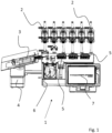
- FIG. 1 shows a system 1 for the production of a medicinal preparation.
- the system 1 for producing a medicinal preparation comprises a large number of source containers 2, which are only partially shown in this view.
- those source containers are not shown in this representation, which contain the main components of the medicinal preparation, as well as the container that is filled with universal liquid.
- these containers can be hung remotely from the system, e.g. on a hook attached to a rail.
- a target container 3 embodied as an infusion bag can be seen, which is arranged on scales 4 .
- the amount of liquid transferred to the target container 3 can be checked via the scales 4 during operation of the system 1 .
- a transfer set which comprises a valve unit 5 and hoses, by means of which the valve unit 5 is connected to the target container 3 on the one hand and to the source containers 2 on the other.
- valve of the valve unit 5 is opened via the system 1 in each dosing step, so that liquid can be pumped from exactly one source container 2 into the target container 3 .
- the system 1 has a single peristaltic pump 6 here, by means of which liquids can be pumped from all the source containers 2 into the target container 3 .
- the system 1 also has a display 7, which is e.g. designed as a touch screen, by means of which the user can program the system 1 and in particular select a program, by means of which a target container 3 is filled with a predetermined composition of components.
- a display 7 which is e.g. designed as a touch screen, by means of which the user can program the system 1 and in particular select a program, by means of which a target container 3 is filled with a predetermined composition of components.
- the system includes an electronic controller (not shown) via which the peristaltic pump 6 is controlled and which is connected to the scale 4 .
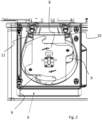
- 2 12 is a detailed view of the peristaltic pump 6. This is preferably provided here as a roller pump.
- the hose pump 6 has a pump wheel 8 with two rollers 9 .
- the hose to be inserted is not shown in this view.
- the method according to the invention can also be carried out using a hose pump with a different number of rollers, in particular using a hose pump which has three rollers (not shown).
- the tube pump has an inlet 10 and an outlet 11 . In the position of the impeller 8 shown here, both rollers 9 are in engagement with the hose.
- rollers 9 move from the outlet 11 to the inlet 10, they are partly disengaged from the hose. This results both on the suction side, ie on the side of the inlet 10, and on the pressure side, ie on the side of the outlet 11, a non-linear characteristic curve of the pump power, the peristaltic pump pulsates.
- the amount of liquid delivered is between 5 and 50 ml per full revolution.
- the peristaltic pump 6 is brought into a position by turning the pump wheel 8 in which the respective micro-amount is completely in the linear range, at least on the suction side the peristaltic pump 6 can be dosed.
- the peristaltic pump includes a rotary encoder (not shown).
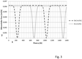
- the pressure-side and suction-side characteristics are in 3 shown.
- phase angle p is divided into 1600 units, which are plotted on the x-axis. These 1600 steps represent one full revolution of the pump.
- the differential flow i.e. the volume delivered per unit of angle of rotation, is plotted on the y-axis for the peristaltic pump.
- the dashed curve represents the differential flow on the pressure side and the dotted curve represents the differential flow on the suction side.
- the characteristic curves are constant over wide areas, i.e. there are areas with a linear characteristic curve.
- the dips are in the areas where a roller comes out of engagement.
- the tubing of the peristaltic pump returns to its original shape.
- the hose increases in volume and the delivery rate of the pump is reduced on the pressure side.
- the pumped volume on the suction side is relevant for the exact dosing, especially of a micro quantity. All liquid that is taken from the source container in the respective dosing step ultimately reaches the target container. It is therefore crucial that the correct volume is removed from the suction side in each dosing step.
- liquid is conveyed in only one of the two linear areas of the suction side of the pump.
- the peristaltic pump is preferably switched to the beginning of the next linear range while pumping universal liquid placed on the suction side.
- the suction-side characteristic of the peristaltic pump is preferably used to more accurately calculate the amount of liquid withdrawn from the source container.
- the characteristic curve on the suction side of the hose pump can also be used for dosing steps that take place in the non-linear range of the hose pump in order to calculate the quantities of liquid removed.
- the calculation takes into account that the suction-side flow rate of the peristaltic pump is not linear.
- p1 is the position of the impeller at the beginning of the dosing step and p2 is the position after the dosing step.
- Vs is the volume to be taken from the source container.
- the pressure-side characteristic curve of the pump can in turn be used to check in an improved way by weighing the target container whether the quantity actually removed corresponds to the calculated quantity.
- the volume of the liquid entering the target container is calculated. Furthermore, the mass of the incoming liquid is calculated based on the known density of the pumped liquid. The characteristic curve Dd of the pressure side is used to determine the volume of the liquid arriving in the target container.
- the characteristic curves which are preferably determined by empirical measurements, can be stored, for example, as approximate formulas or also as a simple table of values, in order to calculate the suction-side and pressure-side pump power as a function of the phase angle.
- the characteristics can be determined by measurement and then approximated by an empirical formula. The calculations in the system are then carried out using the empirical formula or a table of values.
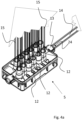
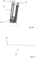
- FIG. 14 is a perspective view of the valve unit 5 used for the medicinal preparation manufacturing plant.
- the valve unit 5 comprises a large number of inlets 12, which are connected to the source containers (2 in 1 ) get connected. Valves (not shown) integrated in the valve unit 5 can selectively connect a hose 15 , by means of which liquid is removed from a source container, to a hose 14 which is arranged on the outlet 13 of the valve unit 5 .
- the hose 14 also has a section which is inserted into the hose pump.
- FIG 4b the ends of the hoses 15 for connecting the source container are shown.
- the connections 22 for the source container can be seen, which in this exemplary embodiment are in the form of a Luer lock connection with an attached spike.
- Figure 4c shows the tube 14, which forms the outlet of the valve unit 5 and at the same time the inlet of the target container. Connection 23 for the target container can be seen.
- valve unit 5 shown here forms, together with the hoses 14, 15 and their connections 22, 23, the transfer set, which is used to operate the system.
- This transfer set is preferably designed as a disposable component and is regularly replaced. Because of this configuration, the liquids to be transferred only come into contact with components of the transfer set on the way from the source container to the target container.
- the transfer set described above is used to connect the source containers.
- a so-called "waste bag” is inserted as a target container, ie a container which is not intended to be used as intended for applying a medicinal preparation, but which is discarded after the system has been prepared.
- the entire transfer set including tubing, is filled with universal fluid (UI), such as isotonic water, and each valve is opened long enough for the tubing (15 in Figure 4a , b ) leading to the source tanks are filled and free of bubbles.
- UI universal fluid
- the dosing factor of the peristaltic pump can be determined by weighing the waste bag when pumping universal liquid.
- the pump capacity of the hose pump which changes due in particular to tolerances in the hose used, is now calibrated by determining this dosing factor.
- the waste bag is then discarded and the first target container, which is to be filled with a medicinal preparation, can be connected.
- a micro-amount is to be dosed in a first dosing step.
- step 5 the impeller is brought into an area with a linear characteristic curve on the suction side, with universal fluid first being conveyed while the impeller is brought into this position.
- a micro-quantity can now be removed from the source container completely in the linear range of the pump's characteristic curve on the suction side.
- Each individual dosing step including the step of dosing a micro-quantity, is checked by weighing the target container.
- the density of the liquid transferred into the target container is taken into account by calculating which liquid or which liquids are in the inlet of the target container when the microquantity is removed in step 5 and are transferred into it.
- a main component of the medicinal preparation is then dosed, taking into account the suction-side characteristic curve of the peristaltic pump.
- the peristaltic pump is also operated in the non-linear range when dosing the main components.
- the suction-side characteristic curve of the peristaltic pump is taken into account in order to be able to precisely predict the volume removed on the suction side.
- the quantity taken from the source container for a main component is also checked, taking into account the density of the liquid transferred to the target container and taking into account the pressure-side characteristic curve of the peristaltic pump.
- a flow factor is preferably included as a further factor in the calculation of the volume of the delivered liquid, which is dependent on the type, in particular the viscosity, of the delivered liquid.
- a flow factor of 1.0 is assigned to water; the flow factor changes significantly in the case of viscous components such as glucose solutions.
- Vs is the volume to be dosed in one dosing step. This corresponds to the volume of the suction side to which a source tank is connected.
- p1 is the position of the impeller before the dosing step, in particular the end position of a previous dosing step or the start of the linear range in which the impeller was previously rotated.
- p2 is the calculated position of the impeller after the dosing step, i.e. the result of the calculation for the rotation angle of the pump in the dosing step.
- F is the flow factor, i.e. the correction factor for the respective viscosity of the medium.
- Ds(p) is the characteristic of the suction side (constant) and p is the phase of the impeller.
- the phases p1 and p2 can differ by several revolutions.
- the flow factor F is therefore a correction for an additional slippage of the pump due to increased viscosity compared to water.
- the volume to be dosed is set higher by a factor of F than with water.
- Vd is the volume expected on the pressure side, i.e. the volume of liquid that is pumped into the target container on the scale during the dosing step.
- Dd(p) is characteristic of the pressure side.
- the flow factor F goes into the calculation of the volume pumped on the pressure side, since the "slip" of the pump is not pumped.
- G Vd ⁇ ⁇ with the density ⁇ of the conveyed medium.
- ⁇ is therefore the specific weight of the liquid transferred into the target container during a dosing step, i.e. initially the liquid that is already present in the inlet of the target container. If several different liquids are transferred to the target container during a dosing step, the specific gravity of the liquids is set in relation to their quantity.
- Steps 5 to 9 can therefore be repeated until all the desired components are in the target container.
- steps 5 to 7, ie the dosing of a micro-amount, and steps 8 and 9, ie the dosing of a main component, are also interchangeable, ie can be carried out in a different order.
- the transfer set is rinsed with universal liquid and, if necessary, the desired residual amount of universal liquid is fed to the target container.
- this rinsing phase in which the impeller of the peristaltic pump rotates more than one full revolution, to re-determine the dosing factor of the peristaltic pump during operation by weighing the target container.
- the dosing factor can thus be recalibrated during operation. This can change, for example, because the elasticity and shape of the hose inserted into the hose pump changes.
- the target container After completing all dosing steps and rinsing the transfer set, the target container can be removed and a new target container connected.
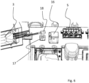
- FIG. 6 is another detail of the 1 .
- the target container 3 can again be seen.
- a valve unit 5 can also be seen.
- the hose not shown here, which connects the valve unit 5 to the target container 3 and which is placed in particular in the hose pump, is first placed in a flow sensor 16 .
- the flow rate in the hose on the suction side is measured via the flow sensor 16 and the delivery capacity of the hose pump can thus be checked for plausibility. If, for example, there is a blockage in the area of the valve unit or at the connection of a source container, the throughflow on the suction side will be reduced to such an extent that an error can be detected by means of the flow sensor 16 . In particular when dosing a micro-amount, the tube will initially also contract in the area of the flow sensor 16, with the result that the detected flow rate is reduced and a blockage can be concluded. An error message can then be generated via the electronic control and displayed to the user.
- the flow sensor 16 is preferably designed as an ultrasonic sensor. In particular at low flow rates, such a sensor is generally not accurate enough to be able to determine the quantity of liquid conveyed on the suction side with sufficient accuracy using the flow sensor alone.
- the flow sensor is therefore preferably used solely for monitoring such that an error is assumed if the difference between the calculated pump capacity of the peristaltic pump and the resulting calculated flow rate compared to the flow rate determined by the flow sensor exceeds a threshold value.
- the hose is placed in a bubble sensor 17 on the pressure side.
- This is an ultrasonic sensor that detects bubbles and switches off the system from a certain threshold value and displays an error to the user.
- FIG. 12 is a schematic representation of the hose 14 connecting the valve unit 5 to the target container 3.
- FIG. 12 In this exemplary embodiment, three valve units connected in series are shown, but this has no effect on the basic principle.
- the three valve units 5 shown here can just as easily be combined into a single valve unit.
- the inlet to a source container is opened by means of the valve unit 5 for each dosing step, so that liquid can flow from the source container via the respective valve of the valve unit first into the valve unit and then into the hose 14 .
- the tube 14 and the collecting channels 22 of the valve units 5 form a volume into which the liquid taken from the respective source containers is initially transferred.
- the calculation of the weight of the liquid which arrives in the target container 3 in a dosing step is therefore not based on the density of the liquid removed in the respective dosing step. Rather, the tube 14 and the collecting channels 24 of the valve unit(s) 5 are considered in such a way that different liquids, namely a first liquid 19, a second liquid 20 and a third liquid 21, are in different sections of the tube 14 and/or the subsequent collecting channel 24 located.
- the specific weight of the first liquid 19 is initially taken as a basis.
- Fig. 12 is a flowchart used to explain verification of each dosing step by weighing the target container.
- the weight transferred to the target container is calculated as a target weight. As described above, this is done on the basis of the pressure-side characteristic curve of the peristaltic pump and the specific gravity of the liquid transferred to the target container.
- the filling process is aborted and an error message appears .
- the user can then correct the error if necessary, insert a waste bag and recalibrate the system.
- the filling process is continued.
- the user of the system receives a message that the system needs to be calibrated.
- next target container can be inserted after the filling process is complete.
- FIG. 12 is a flow chart used to explain the calculation of the target weight in a dosing step.
- the volume of the liquid introduced is calculated using the pressure-side characteristic of the peristaltic pump.
- the target weight can then be calculated from the specific weight of the transferred liquid or liquids.
- This target weight is used to determine the in 8 mentioned limit values.
- a first limit range could be defined as a deviation of more than 10% and a second limit range as a deviation of more than 5%.
- limit ranges can also be varied as a function of the liquid removed during a dosing step, since there are components for which deviations in quantity are more or less critical for the quality of the medicinal preparation.
- Fig. 12 is a flow chart for explaining the bubble sensor control.
- the amount of bubbles in the transferred liquid is continuously monitored by the bubble sensor located after the peristaltic pump.
- the filling process is interrupted and an error message is displayed.
- next target container can be inserted after the filling process is complete
- Fig. 12 is a flowchart for explaining flow sensor control.
- the flow rate is continuously calculated, preferably on the basis of the suction-side characteristic curve of the peristaltic pump.
- the flow rate is measured with a flow sensor arranged on the flow side in front of the peristaltic pump.
- a deviation above a threshold value in this example 20%, an error (e.g. occlusion) is assumed and the filling process is aborted.
- the user is informed of an error message.
- the source container is preferably displayed to the user (e.g. via a number on a screen) in the event of any error message, from which liquid was taken when the error occurred.
- the invention can improve accuracy in manufacturing a medicinal preparation using a tube pump.
Landscapes
- Health & Medical Sciences (AREA)
- Heart & Thoracic Surgery (AREA)
- Urology & Nephrology (AREA)
- Life Sciences & Earth Sciences (AREA)
- Veterinary Medicine (AREA)
- Animal Behavior & Ethology (AREA)
- General Health & Medical Sciences (AREA)
- Public Health (AREA)
- Vascular Medicine (AREA)
- Biomedical Technology (AREA)
- Engineering & Computer Science (AREA)
- Anesthesiology (AREA)
- Hematology (AREA)
- Emergency Medicine (AREA)
- Chemical & Material Sciences (AREA)
- Nutrition Science (AREA)
- Medicinal Chemistry (AREA)
- Pharmacology & Pharmacy (AREA)
- Cardiology (AREA)
- Infusion, Injection, And Reservoir Apparatuses (AREA)
- Pharmaceuticals Containing Other Organic And Inorganic Compounds (AREA)
Applications Claiming Priority (2)
| Application Number | Priority Date | Filing Date | Title |
|---|---|---|---|
| EP16160328 | 2016-03-15 | ||
| PCT/EP2017/056106 WO2017158011A1 (de) | 2016-03-15 | 2017-03-15 | Verfahren zur herstellung einer medizinischen zubereitung unter verwendung einer schlauchpumpe |
Publications (2)
| Publication Number | Publication Date |
|---|---|
| EP3429544A1 EP3429544A1 (de) | 2019-01-23 |
| EP3429544B1 true EP3429544B1 (de) | 2023-04-19 |
Family
ID=55646295
Family Applications (1)
| Application Number | Title | Priority Date | Filing Date |
|---|---|---|---|
| EP17710303.3A Active EP3429544B1 (de) | 2016-03-15 | 2017-03-15 | Verfahren zur herstellung einer medizinischen zubereitung unter verwendung einer schlauchpumpe |
Country Status (6)
| Country | Link |
|---|---|
| US (1) | US11077023B2 (pl) |
| EP (1) | EP3429544B1 (pl) |
| CN (1) | CN108778227B (pl) |
| ES (1) | ES2945432T3 (pl) |
| PL (1) | PL3429544T3 (pl) |
| WO (1) | WO2017158011A1 (pl) |
Families Citing this family (5)
| Publication number | Priority date | Publication date | Assignee | Title |
|---|---|---|---|---|
| WO2017158009A1 (de) | 2016-03-15 | 2017-09-21 | Fresenius Kabi Deutschland Gmbh | Anlage zur herstellung einer medizinischen zubereitung |
| WO2022020184A1 (en) * | 2020-07-21 | 2022-01-27 | Icu Medical, Inc. | Fluid transfer devices and methods of use |
| US20240293786A1 (en) * | 2021-06-30 | 2024-09-05 | Scinogy Products Pty Ltd | Small volume liquid mixing and dispensing system and method |
| CN119173446A (zh) | 2022-03-08 | 2024-12-20 | 赤盾医疗有限公司 | 机器人药物制备系统中的流体转移站 |
| CN116570155A (zh) * | 2023-04-06 | 2023-08-11 | 四川黑菠萝科技有限公司 | 一种精确配料的奶茶机及奶茶精确配料方法 |
Family Cites Families (11)
| Publication number | Priority date | Publication date | Assignee | Title |
|---|---|---|---|---|
| US4473173A (en) | 1983-01-10 | 1984-09-25 | Applied Color Systems, Inc. | Apparatus and method for low volume dispensing |
| US4718467A (en) * | 1986-05-30 | 1988-01-12 | Baxter Travenol Laboratories, Inc. | Pumping module arrangement and manifold |
| US5228485A (en) | 1986-12-08 | 1993-07-20 | Clintec Nutrition Co. | Flexible tubing occlusion sensor |
| US5040699A (en) * | 1989-05-15 | 1991-08-20 | Gangemi Ronald J | Fluid compounding method and apparatus |
| DE3938898A1 (de) | 1989-11-24 | 1991-05-29 | Sartorius Gmbh | Verfahren und vorrichtung zum pulsationsfreien kontinuierlichen gravimetrischen dosieren |
| US5697407A (en) | 1995-11-30 | 1997-12-16 | The Metrix Company | Compounding system for multiple chamber receptacles |
| US5927349A (en) * | 1996-12-09 | 1999-07-27 | Baxter International Inc. | Compounding assembly for nutritional fluids |
| US6199603B1 (en) * | 1998-08-14 | 2001-03-13 | Baxter International Inc. | Compounding assembly for nutritional fluids |
| US7645127B2 (en) | 2003-04-29 | 2010-01-12 | Loren Hagen | Pulseless peristaltic pump |
| WO2010054327A1 (en) * | 2008-11-10 | 2010-05-14 | Delphi Technologies, Inc. | Method and apparatus for a peristaltic pump |
| CN104912786B (zh) * | 2015-06-05 | 2017-03-01 | 深圳市清时捷科技有限公司 | 一种移液泵校准装置及校准方法 |
-
2017
- 2017-03-15 EP EP17710303.3A patent/EP3429544B1/de active Active
- 2017-03-15 PL PL17710303.3T patent/PL3429544T3/pl unknown
- 2017-03-15 ES ES17710303T patent/ES2945432T3/es active Active
- 2017-03-15 CN CN201780018023.7A patent/CN108778227B/zh active Active
- 2017-03-15 WO PCT/EP2017/056106 patent/WO2017158011A1/de not_active Ceased
- 2017-03-15 US US16/083,984 patent/US11077023B2/en active Active
Also Published As
| Publication number | Publication date |
|---|---|
| EP3429544A1 (de) | 2019-01-23 |
| CN108778227B (zh) | 2022-01-14 |
| US20200289372A1 (en) | 2020-09-17 |
| CN108778227A (zh) | 2018-11-09 |
| US11077023B2 (en) | 2021-08-03 |
| ES2945432T3 (es) | 2023-07-03 |
| PL3429544T3 (pl) | 2023-06-26 |
| WO2017158011A1 (de) | 2017-09-21 |
Similar Documents
| Publication | Publication Date | Title |
|---|---|---|
| EP3429544B1 (de) | Verfahren zur herstellung einer medizinischen zubereitung unter verwendung einer schlauchpumpe | |
| EP3429546B1 (de) | Verfahren zur herstellung einer medizinischen zubereitung | |
| DE102011106113B4 (de) | Verfahren und Vorrichtung zum Überprüfen der Förderleistung mindestens eines ersten und eines zweiten Fördermittels einer Vorrichtung zur extrakorporalen Blutbehandlung | |
| EP2717938B1 (de) | Verfahren und vorrichtung zum bestimmen mindestens eines vom absolutdruck abhängigen betriebsparameters einer vorrichtung zur extrakorporalen blutbehandlung, vorrichtung zur extrakorporalen blutbehandlung | |
| EP3953058B1 (de) | Applikationseinrichtung und entsprechendes applikationsverfahren | |
| DE3329977A1 (de) | Vorrichtung zur dosierten gleichzeitigen infusion von loesungen | |
| EP1163917A1 (de) | Dialysevorrichtung mit einer Ausgleichskammer und Verfahren zum Betreiben der Dialysevorrichtung | |
| DE3215330A1 (de) | Infusionsapparat | |
| EP3648812B1 (de) | Pumpsystem und dialysegerät | |
| WO2006125671A1 (de) | Vorrichtung und verfahren zur förderung medizinischer flüssigkeiten | |
| DE102013015313A1 (de) | Applikationsanlage und entsprechendes Applikationsverfahren | |
| EP3395382B1 (de) | Verfahren und vorrichtung zur intermittierenden, pulsierenden proportionierung einer dialysierflüssigkeitsmischung | |
| WO2013045711A1 (de) | Verfahren und vorrichtung zum dosieren eines arbeitsfluids | |
| WO2014078883A2 (de) | Mischanlage für viskose medien | |
| DE68917590T2 (de) | Herstellung einer mischung aus flüssigkeiten. | |
| DE10034368C1 (de) | Dialysevorrichtung und Verfahren zum Betreiben einer Dialysevorrichtung | |
| WO2018134045A1 (de) | Dialysatkonzentration-messsensordiagnose | |
| DE102004051537B4 (de) | Dosiersystem für fluide Medien | |
| DE69007342T3 (de) | Verfahren zur Kontrolle der Ultrafiltration und Vorrichtung zur Ausführung des Verfahrens. | |
| DE3018205A1 (de) | Verfahren zum dosieren von bindemitteln fuer die beleimung von spaenen, fasern o.dgl. fuer die spanplattenherstellung sowie vorrichtung zur durchfuehrung des verfahrens | |
| EP1384503B1 (de) | Verfahren und Vorrichtung zum dosierten Mischen von pumpfähigen Stoffen | |
| DE102018121080A1 (de) | Verfahren und Vorrichtung zur intermittierenden, pulsierenden Proportionierung einer Dialysierflüssigkeitsmischung | |
| WO2020152276A1 (de) | Verfahren zum überprüfen der fördergenauigkeit von fördermitteln einer medizinischen behandlungsvorrichtung, und vorrichtungen | |
| EP3290064A1 (de) | System zur messung einer menge an flüssigkeit in einem elastischen beutel | |
| DE102009040496A1 (de) | Tubenfüllmaschine und Verfahren zur Steuerung einer Dosierpumpe insbesondere in einer Tubenfüllmaschine |
Legal Events
| Date | Code | Title | Description |
|---|---|---|---|
| STAA | Information on the status of an ep patent application or granted ep patent |
Free format text: STATUS: UNKNOWN |
|
| STAA | Information on the status of an ep patent application or granted ep patent |
Free format text: STATUS: THE INTERNATIONAL PUBLICATION HAS BEEN MADE |
|
| PUAI | Public reference made under article 153(3) epc to a published international application that has entered the european phase |
Free format text: ORIGINAL CODE: 0009012 |
|
| STAA | Information on the status of an ep patent application or granted ep patent |
Free format text: STATUS: REQUEST FOR EXAMINATION WAS MADE |
|
| 17P | Request for examination filed |
Effective date: 20181002 |
|
| AK | Designated contracting states |
Kind code of ref document: A1 Designated state(s): AL AT BE BG CH CY CZ DE DK EE ES FI FR GB GR HR HU IE IS IT LI LT LU LV MC MK MT NL NO PL PT RO RS SE SI SK SM TR |
|
| AX | Request for extension of the european patent |
Extension state: BA ME |
|
| DAV | Request for validation of the european patent (deleted) | ||
| DAX | Request for extension of the european patent (deleted) | ||
| STAA | Information on the status of an ep patent application or granted ep patent |
Free format text: STATUS: EXAMINATION IS IN PROGRESS |
|
| 17Q | First examination report despatched |
Effective date: 20190920 |
|
| REG | Reference to a national code |
Ref country code: HK Ref legal event code: DE Ref document number: 40002035 Country of ref document: HK |
|
| GRAP | Despatch of communication of intention to grant a patent |
Free format text: ORIGINAL CODE: EPIDOSNIGR1 |
|
| STAA | Information on the status of an ep patent application or granted ep patent |
Free format text: STATUS: GRANT OF PATENT IS INTENDED |
|
| INTG | Intention to grant announced |
Effective date: 20221018 |
|
| GRAS | Grant fee paid |
Free format text: ORIGINAL CODE: EPIDOSNIGR3 |
|
| GRAA | (expected) grant |
Free format text: ORIGINAL CODE: 0009210 |
|
| STAA | Information on the status of an ep patent application or granted ep patent |
Free format text: STATUS: THE PATENT HAS BEEN GRANTED |
|
| AK | Designated contracting states |
Kind code of ref document: B1 Designated state(s): AL AT BE BG CH CY CZ DE DK EE ES FI FR GB GR HR HU IE IS IT LI LT LU LV MC MK MT NL NO PL PT RO RS SE SI SK SM TR |
|
| REG | Reference to a national code |
Ref country code: GB Ref legal event code: FG4D Free format text: NOT ENGLISH |
|
| REG | Reference to a national code |
Ref country code: DE Ref legal event code: R096 Ref document number: 502017014632 Country of ref document: DE |
|
| REG | Reference to a national code |
Ref country code: CH Ref legal event code: EP |
|
| REG | Reference to a national code |
Ref country code: IE Ref legal event code: FG4D Free format text: LANGUAGE OF EP DOCUMENT: GERMAN |
|
| REG | Reference to a national code |
Ref country code: AT Ref legal event code: REF Ref document number: 1560684 Country of ref document: AT Kind code of ref document: T Effective date: 20230515 |
|
| REG | Reference to a national code |
Ref country code: ES Ref legal event code: FG2A Ref document number: 2945432 Country of ref document: ES Kind code of ref document: T3 Effective date: 20230703 |
|
| REG | Reference to a national code |
Ref country code: LT Ref legal event code: MG9D |
|
| REG | Reference to a national code |
Ref country code: NL Ref legal event code: MP Effective date: 20230419 |
|
| PG25 | Lapsed in a contracting state [announced via postgrant information from national office to epo] |
Ref country code: NL Free format text: LAPSE BECAUSE OF FAILURE TO SUBMIT A TRANSLATION OF THE DESCRIPTION OR TO PAY THE FEE WITHIN THE PRESCRIBED TIME-LIMIT Effective date: 20230419 |
|
| PG25 | Lapsed in a contracting state [announced via postgrant information from national office to epo] |
Ref country code: SE Free format text: LAPSE BECAUSE OF FAILURE TO SUBMIT A TRANSLATION OF THE DESCRIPTION OR TO PAY THE FEE WITHIN THE PRESCRIBED TIME-LIMIT Effective date: 20230419 Ref country code: PT Free format text: LAPSE BECAUSE OF FAILURE TO SUBMIT A TRANSLATION OF THE DESCRIPTION OR TO PAY THE FEE WITHIN THE PRESCRIBED TIME-LIMIT Effective date: 20230821 Ref country code: NO Free format text: LAPSE BECAUSE OF FAILURE TO SUBMIT A TRANSLATION OF THE DESCRIPTION OR TO PAY THE FEE WITHIN THE PRESCRIBED TIME-LIMIT Effective date: 20230719 |
|
| PG25 | Lapsed in a contracting state [announced via postgrant information from national office to epo] |
Ref country code: RS Free format text: LAPSE BECAUSE OF FAILURE TO SUBMIT A TRANSLATION OF THE DESCRIPTION OR TO PAY THE FEE WITHIN THE PRESCRIBED TIME-LIMIT Effective date: 20230419 Ref country code: LV Free format text: LAPSE BECAUSE OF FAILURE TO SUBMIT A TRANSLATION OF THE DESCRIPTION OR TO PAY THE FEE WITHIN THE PRESCRIBED TIME-LIMIT Effective date: 20230419 Ref country code: LT Free format text: LAPSE BECAUSE OF FAILURE TO SUBMIT A TRANSLATION OF THE DESCRIPTION OR TO PAY THE FEE WITHIN THE PRESCRIBED TIME-LIMIT Effective date: 20230419 Ref country code: IS Free format text: LAPSE BECAUSE OF FAILURE TO SUBMIT A TRANSLATION OF THE DESCRIPTION OR TO PAY THE FEE WITHIN THE PRESCRIBED TIME-LIMIT Effective date: 20230819 Ref country code: HR Free format text: LAPSE BECAUSE OF FAILURE TO SUBMIT A TRANSLATION OF THE DESCRIPTION OR TO PAY THE FEE WITHIN THE PRESCRIBED TIME-LIMIT Effective date: 20230419 Ref country code: GR Free format text: LAPSE BECAUSE OF FAILURE TO SUBMIT A TRANSLATION OF THE DESCRIPTION OR TO PAY THE FEE WITHIN THE PRESCRIBED TIME-LIMIT Effective date: 20230720 Ref country code: AL Free format text: LAPSE BECAUSE OF FAILURE TO SUBMIT A TRANSLATION OF THE DESCRIPTION OR TO PAY THE FEE WITHIN THE PRESCRIBED TIME-LIMIT Effective date: 20230419 |
|
| PG25 | Lapsed in a contracting state [announced via postgrant information from national office to epo] |
Ref country code: FI Free format text: LAPSE BECAUSE OF FAILURE TO SUBMIT A TRANSLATION OF THE DESCRIPTION OR TO PAY THE FEE WITHIN THE PRESCRIBED TIME-LIMIT Effective date: 20230419 |
|
| PG25 | Lapsed in a contracting state [announced via postgrant information from national office to epo] |
Ref country code: SK Free format text: LAPSE BECAUSE OF FAILURE TO SUBMIT A TRANSLATION OF THE DESCRIPTION OR TO PAY THE FEE WITHIN THE PRESCRIBED TIME-LIMIT Effective date: 20230419 |
|
| REG | Reference to a national code |
Ref country code: DE Ref legal event code: R097 Ref document number: 502017014632 Country of ref document: DE |
|
| PG25 | Lapsed in a contracting state [announced via postgrant information from national office to epo] |
Ref country code: SM Free format text: LAPSE BECAUSE OF FAILURE TO SUBMIT A TRANSLATION OF THE DESCRIPTION OR TO PAY THE FEE WITHIN THE PRESCRIBED TIME-LIMIT Effective date: 20230419 Ref country code: SK Free format text: LAPSE BECAUSE OF FAILURE TO SUBMIT A TRANSLATION OF THE DESCRIPTION OR TO PAY THE FEE WITHIN THE PRESCRIBED TIME-LIMIT Effective date: 20230419 Ref country code: RO Free format text: LAPSE BECAUSE OF FAILURE TO SUBMIT A TRANSLATION OF THE DESCRIPTION OR TO PAY THE FEE WITHIN THE PRESCRIBED TIME-LIMIT Effective date: 20230419 Ref country code: EE Free format text: LAPSE BECAUSE OF FAILURE TO SUBMIT A TRANSLATION OF THE DESCRIPTION OR TO PAY THE FEE WITHIN THE PRESCRIBED TIME-LIMIT Effective date: 20230419 Ref country code: DK Free format text: LAPSE BECAUSE OF FAILURE TO SUBMIT A TRANSLATION OF THE DESCRIPTION OR TO PAY THE FEE WITHIN THE PRESCRIBED TIME-LIMIT Effective date: 20230419 Ref country code: CZ Free format text: LAPSE BECAUSE OF FAILURE TO SUBMIT A TRANSLATION OF THE DESCRIPTION OR TO PAY THE FEE WITHIN THE PRESCRIBED TIME-LIMIT Effective date: 20230419 |
|
| PLBE | No opposition filed within time limit |
Free format text: ORIGINAL CODE: 0009261 |
|
| STAA | Information on the status of an ep patent application or granted ep patent |
Free format text: STATUS: NO OPPOSITION FILED WITHIN TIME LIMIT |
|
| 26N | No opposition filed |
Effective date: 20240122 |
|
| PG25 | Lapsed in a contracting state [announced via postgrant information from national office to epo] |
Ref country code: SI Free format text: LAPSE BECAUSE OF FAILURE TO SUBMIT A TRANSLATION OF THE DESCRIPTION OR TO PAY THE FEE WITHIN THE PRESCRIBED TIME-LIMIT Effective date: 20230419 |
|
| PG25 | Lapsed in a contracting state [announced via postgrant information from national office to epo] |
Ref country code: SI Free format text: LAPSE BECAUSE OF FAILURE TO SUBMIT A TRANSLATION OF THE DESCRIPTION OR TO PAY THE FEE WITHIN THE PRESCRIBED TIME-LIMIT Effective date: 20230419 |
|
| REG | Reference to a national code |
Ref country code: CH Ref legal event code: PL |
|
| PG25 | Lapsed in a contracting state [announced via postgrant information from national office to epo] |
Ref country code: BG Free format text: LAPSE BECAUSE OF FAILURE TO SUBMIT A TRANSLATION OF THE DESCRIPTION OR TO PAY THE FEE WITHIN THE PRESCRIBED TIME-LIMIT Effective date: 20230419 |
|
| PG25 | Lapsed in a contracting state [announced via postgrant information from national office to epo] |
Ref country code: LU Free format text: LAPSE BECAUSE OF NON-PAYMENT OF DUE FEES Effective date: 20240315 |
|
| PG25 | Lapsed in a contracting state [announced via postgrant information from national office to epo] |
Ref country code: MC Free format text: LAPSE BECAUSE OF FAILURE TO SUBMIT A TRANSLATION OF THE DESCRIPTION OR TO PAY THE FEE WITHIN THE PRESCRIBED TIME-LIMIT Effective date: 20230419 |
|
| PG25 | Lapsed in a contracting state [announced via postgrant information from national office to epo] |
Ref country code: MC Free format text: LAPSE BECAUSE OF FAILURE TO SUBMIT A TRANSLATION OF THE DESCRIPTION OR TO PAY THE FEE WITHIN THE PRESCRIBED TIME-LIMIT Effective date: 20230419 Ref country code: LU Free format text: LAPSE BECAUSE OF NON-PAYMENT OF DUE FEES Effective date: 20240315 Ref country code: BG Free format text: LAPSE BECAUSE OF FAILURE TO SUBMIT A TRANSLATION OF THE DESCRIPTION OR TO PAY THE FEE WITHIN THE PRESCRIBED TIME-LIMIT Effective date: 20230419 |
|
| REG | Reference to a national code |
Ref country code: BE Ref legal event code: MM Effective date: 20240331 |
|
| PG25 | Lapsed in a contracting state [announced via postgrant information from national office to epo] |
Ref country code: BE Free format text: LAPSE BECAUSE OF NON-PAYMENT OF DUE FEES Effective date: 20240331 |
|
| PG25 | Lapsed in a contracting state [announced via postgrant information from national office to epo] |
Ref country code: IE Free format text: LAPSE BECAUSE OF NON-PAYMENT OF DUE FEES Effective date: 20240315 |
|
| PG25 | Lapsed in a contracting state [announced via postgrant information from national office to epo] |
Ref country code: IE Free format text: LAPSE BECAUSE OF NON-PAYMENT OF DUE FEES Effective date: 20240315 Ref country code: BE Free format text: LAPSE BECAUSE OF NON-PAYMENT OF DUE FEES Effective date: 20240331 Ref country code: CH Free format text: LAPSE BECAUSE OF NON-PAYMENT OF DUE FEES Effective date: 20240331 |
|
| PGFP | Annual fee paid to national office [announced via postgrant information from national office to epo] |
Ref country code: PL Payment date: 20250207 Year of fee payment: 9 |
|
| PGFP | Annual fee paid to national office [announced via postgrant information from national office to epo] |
Ref country code: IT Payment date: 20250306 Year of fee payment: 9 |
|
| PGFP | Annual fee paid to national office [announced via postgrant information from national office to epo] |
Ref country code: MT Payment date: 20250207 Year of fee payment: 9 |
|
| REG | Reference to a national code |
Ref country code: AT Ref legal event code: MM01 Ref document number: 1560684 Country of ref document: AT Kind code of ref document: T Effective date: 20240315 |
|
| PGFP | Annual fee paid to national office [announced via postgrant information from national office to epo] |
Ref country code: ES Payment date: 20250403 Year of fee payment: 9 |
|
| PG25 | Lapsed in a contracting state [announced via postgrant information from national office to epo] |
Ref country code: AT Free format text: LAPSE BECAUSE OF NON-PAYMENT OF DUE FEES Effective date: 20240315 |
|
| PG25 | Lapsed in a contracting state [announced via postgrant information from national office to epo] |
Ref country code: CY Free format text: LAPSE BECAUSE OF FAILURE TO SUBMIT A TRANSLATION OF THE DESCRIPTION OR TO PAY THE FEE WITHIN THE PRESCRIBED TIME-LIMIT; INVALID AB INITIO Effective date: 20170315 |
|
| PG25 | Lapsed in a contracting state [announced via postgrant information from national office to epo] |
Ref country code: HU Free format text: LAPSE BECAUSE OF FAILURE TO SUBMIT A TRANSLATION OF THE DESCRIPTION OR TO PAY THE FEE WITHIN THE PRESCRIBED TIME-LIMIT; INVALID AB INITIO Effective date: 20170315 |
|
| PGFP | Annual fee paid to national office [announced via postgrant information from national office to epo] |
Ref country code: GB Payment date: 20260324 Year of fee payment: 10 |
|
| PGFP | Annual fee paid to national office [announced via postgrant information from national office to epo] |
Ref country code: DE Payment date: 20260320 Year of fee payment: 10 |
|
| PGFP | Annual fee paid to national office [announced via postgrant information from national office to epo] |
Ref country code: FR Payment date: 20260327 Year of fee payment: 10 |
|
| PGFP | Annual fee paid to national office [announced via postgrant information from national office to epo] |
Ref country code: TR Payment date: 20260310 Year of fee payment: 10 |