EP3429544B1 - Method for producing a medical preparation using a hose pump - Google Patents
Method for producing a medical preparation using a hose pump Download PDFInfo
- Publication number
- EP3429544B1 EP3429544B1 EP17710303.3A EP17710303A EP3429544B1 EP 3429544 B1 EP3429544 B1 EP 3429544B1 EP 17710303 A EP17710303 A EP 17710303A EP 3429544 B1 EP3429544 B1 EP 3429544B1
- Authority
- EP
- European Patent Office
- Prior art keywords
- liquid
- producing
- target container
- pump
- medical preparation
- Prior art date
- Legal status (The legal status is an assumption and is not a legal conclusion. Google has not performed a legal analysis and makes no representation as to the accuracy of the status listed.)
- Active
Links
- 238000002360 preparation method Methods 0.000 title claims description 55
- 238000004519 manufacturing process Methods 0.000 title claims description 29
- 239000007788 liquid Substances 0.000 claims description 124
- 238000012546 transfer Methods 0.000 claims description 25
- 238000005303 weighing Methods 0.000 claims description 19
- 238000000034 method Methods 0.000 claims description 18
- XLYOFNOQVPJJNP-UHFFFAOYSA-N water Substances O XLYOFNOQVPJJNP-UHFFFAOYSA-N 0.000 claims description 12
- 235000016236 parenteral nutrition Nutrition 0.000 claims description 6
- 238000009434 installation Methods 0.000 claims 2
- 230000002572 peristaltic effect Effects 0.000 description 79
- 238000005429 filling process Methods 0.000 description 13
- 239000002699 waste material Substances 0.000 description 10
- 239000000203 mixture Substances 0.000 description 6
- 238000011161 development Methods 0.000 description 5
- 230000018109 developmental process Effects 0.000 description 5
- 230000000694 effects Effects 0.000 description 4
- 238000005086 pumping Methods 0.000 description 4
- 229940079593 drug Drugs 0.000 description 3
- 239000003814 drug Substances 0.000 description 3
- 238000001802 infusion Methods 0.000 description 3
- 235000021476 total parenteral nutrition Nutrition 0.000 description 3
- 235000013343 vitamin Nutrition 0.000 description 3
- 239000011782 vitamin Substances 0.000 description 3
- 229940088594 vitamin Drugs 0.000 description 3
- 229930003231 vitamin Natural products 0.000 description 3
- WQZGKKKJIJFFOK-GASJEMHNSA-N Glucose Natural products OC[C@H]1OC(O)[C@H](O)[C@@H](O)[C@@H]1O WQZGKKKJIJFFOK-GASJEMHNSA-N 0.000 description 2
- 238000012937 correction Methods 0.000 description 2
- 230000001419 dependent effect Effects 0.000 description 2
- 239000012530 fluid Substances 0.000 description 2
- 239000008103 glucose Substances 0.000 description 2
- 230000005484 gravity Effects 0.000 description 2
- 239000004615 ingredient Substances 0.000 description 2
- 229910052500 inorganic mineral Inorganic materials 0.000 description 2
- 239000000463 material Substances 0.000 description 2
- 238000005259 measurement Methods 0.000 description 2
- 235000010755 mineral Nutrition 0.000 description 2
- 239000011707 mineral Substances 0.000 description 2
- 238000012795 verification Methods 0.000 description 2
- 150000001413 amino acids Chemical class 0.000 description 1
- 238000013329 compounding Methods 0.000 description 1
- 239000000470 constituent Substances 0.000 description 1
- 230000007423 decrease Effects 0.000 description 1
- 235000013305 food Nutrition 0.000 description 1
- 238000012544 monitoring process Methods 0.000 description 1
- 235000015097 nutrients Nutrition 0.000 description 1
- 230000010349 pulsation Effects 0.000 description 1
- 235000013619 trace mineral Nutrition 0.000 description 1
- 239000011573 trace mineral Substances 0.000 description 1
Images


Classifications
-
- A—HUMAN NECESSITIES
- A61—MEDICAL OR VETERINARY SCIENCE; HYGIENE
- A61J—CONTAINERS SPECIALLY ADAPTED FOR MEDICAL OR PHARMACEUTICAL PURPOSES; DEVICES OR METHODS SPECIALLY ADAPTED FOR BRINGING PHARMACEUTICAL PRODUCTS INTO PARTICULAR PHYSICAL OR ADMINISTERING FORMS; DEVICES FOR ADMINISTERING FOOD OR MEDICINES ORALLY; BABY COMFORTERS; DEVICES FOR RECEIVING SPITTLE
- A61J3/00—Devices or methods specially adapted for bringing pharmaceutical products into particular physical or administering forms
- A61J3/002—Compounding apparatus specially for enteral or parenteral nutritive solutions
-
- A—HUMAN NECESSITIES
- A61—MEDICAL OR VETERINARY SCIENCE; HYGIENE
- A61M—DEVICES FOR INTRODUCING MEDIA INTO, OR ONTO, THE BODY; DEVICES FOR TRANSDUCING BODY MEDIA OR FOR TAKING MEDIA FROM THE BODY; DEVICES FOR PRODUCING OR ENDING SLEEP OR STUPOR
- A61M1/00—Suction or pumping devices for medical purposes; Devices for carrying-off, for treatment of, or for carrying-over, body-liquids; Drainage systems
- A61M1/14—Dialysis systems; Artificial kidneys; Blood oxygenators ; Reciprocating systems for treatment of body fluids, e.g. single needle systems for hemofiltration or pheresis
- A61M1/16—Dialysis systems; Artificial kidneys; Blood oxygenators ; Reciprocating systems for treatment of body fluids, e.g. single needle systems for hemofiltration or pheresis with membranes
- A61M1/1621—Constructional aspects thereof
- A61M1/1645—Constructional aspects thereof with mechanically linked peristaltic dialysis fluid pumps one upstream, the other one downstream of the dialyser
-
- A—HUMAN NECESSITIES
- A61—MEDICAL OR VETERINARY SCIENCE; HYGIENE
- A61M—DEVICES FOR INTRODUCING MEDIA INTO, OR ONTO, THE BODY; DEVICES FOR TRANSDUCING BODY MEDIA OR FOR TAKING MEDIA FROM THE BODY; DEVICES FOR PRODUCING OR ENDING SLEEP OR STUPOR
- A61M1/00—Suction or pumping devices for medical purposes; Devices for carrying-off, for treatment of, or for carrying-over, body-liquids; Drainage systems
- A61M1/14—Dialysis systems; Artificial kidneys; Blood oxygenators ; Reciprocating systems for treatment of body fluids, e.g. single needle systems for hemofiltration or pheresis
- A61M1/16—Dialysis systems; Artificial kidneys; Blood oxygenators ; Reciprocating systems for treatment of body fluids, e.g. single needle systems for hemofiltration or pheresis with membranes
- A61M1/1654—Dialysates therefor
- A61M1/1656—Apparatus for preparing dialysates
- A61M1/1668—Details of containers
-
- A—HUMAN NECESSITIES
- A61—MEDICAL OR VETERINARY SCIENCE; HYGIENE
- A61M—DEVICES FOR INTRODUCING MEDIA INTO, OR ONTO, THE BODY; DEVICES FOR TRANSDUCING BODY MEDIA OR FOR TAKING MEDIA FROM THE BODY; DEVICES FOR PRODUCING OR ENDING SLEEP OR STUPOR
- A61M1/00—Suction or pumping devices for medical purposes; Devices for carrying-off, for treatment of, or for carrying-over, body-liquids; Drainage systems
- A61M1/14—Dialysis systems; Artificial kidneys; Blood oxygenators ; Reciprocating systems for treatment of body fluids, e.g. single needle systems for hemofiltration or pheresis
- A61M1/16—Dialysis systems; Artificial kidneys; Blood oxygenators ; Reciprocating systems for treatment of body fluids, e.g. single needle systems for hemofiltration or pheresis with membranes
- A61M1/26—Dialysis systems; Artificial kidneys; Blood oxygenators ; Reciprocating systems for treatment of body fluids, e.g. single needle systems for hemofiltration or pheresis with membranes and internal elements which are moving
- A61M1/262—Dialysis systems; Artificial kidneys; Blood oxygenators ; Reciprocating systems for treatment of body fluids, e.g. single needle systems for hemofiltration or pheresis with membranes and internal elements which are moving rotating
-
- A—HUMAN NECESSITIES
- A61—MEDICAL OR VETERINARY SCIENCE; HYGIENE
- A61M—DEVICES FOR INTRODUCING MEDIA INTO, OR ONTO, THE BODY; DEVICES FOR TRANSDUCING BODY MEDIA OR FOR TAKING MEDIA FROM THE BODY; DEVICES FOR PRODUCING OR ENDING SLEEP OR STUPOR
- A61M1/00—Suction or pumping devices for medical purposes; Devices for carrying-off, for treatment of, or for carrying-over, body-liquids; Drainage systems
- A61M1/14—Dialysis systems; Artificial kidneys; Blood oxygenators ; Reciprocating systems for treatment of body fluids, e.g. single needle systems for hemofiltration or pheresis
- A61M1/16—Dialysis systems; Artificial kidneys; Blood oxygenators ; Reciprocating systems for treatment of body fluids, e.g. single needle systems for hemofiltration or pheresis with membranes
- A61M1/26—Dialysis systems; Artificial kidneys; Blood oxygenators ; Reciprocating systems for treatment of body fluids, e.g. single needle systems for hemofiltration or pheresis with membranes and internal elements which are moving
- A61M1/267—Dialysis systems; Artificial kidneys; Blood oxygenators ; Reciprocating systems for treatment of body fluids, e.g. single needle systems for hemofiltration or pheresis with membranes and internal elements which are moving used for pumping
-
- A—HUMAN NECESSITIES
- A61—MEDICAL OR VETERINARY SCIENCE; HYGIENE
- A61M—DEVICES FOR INTRODUCING MEDIA INTO, OR ONTO, THE BODY; DEVICES FOR TRANSDUCING BODY MEDIA OR FOR TAKING MEDIA FROM THE BODY; DEVICES FOR PRODUCING OR ENDING SLEEP OR STUPOR
- A61M1/00—Suction or pumping devices for medical purposes; Devices for carrying-off, for treatment of, or for carrying-over, body-liquids; Drainage systems
- A61M1/36—Other treatment of blood in a by-pass of the natural circulatory system, e.g. temperature adaptation, irradiation ; Extra-corporeal blood circuits
- A61M1/3621—Extra-corporeal blood circuits
- A61M1/3626—Gas bubble detectors
-
- A—HUMAN NECESSITIES
- A61—MEDICAL OR VETERINARY SCIENCE; HYGIENE
- A61J—CONTAINERS SPECIALLY ADAPTED FOR MEDICAL OR PHARMACEUTICAL PURPOSES; DEVICES OR METHODS SPECIALLY ADAPTED FOR BRINGING PHARMACEUTICAL PRODUCTS INTO PARTICULAR PHYSICAL OR ADMINISTERING FORMS; DEVICES FOR ADMINISTERING FOOD OR MEDICINES ORALLY; BABY COMFORTERS; DEVICES FOR RECEIVING SPITTLE
- A61J2200/00—General characteristics or adaptations
- A61J2200/70—Device provided with specific sensor or indicating means
- A61J2200/74—Device provided with specific sensor or indicating means for weight
-
- F—MECHANICAL ENGINEERING; LIGHTING; HEATING; WEAPONS; BLASTING
- F04—POSITIVE - DISPLACEMENT MACHINES FOR LIQUIDS; PUMPS FOR LIQUIDS OR ELASTIC FLUIDS
- F04B—POSITIVE-DISPLACEMENT MACHINES FOR LIQUIDS; PUMPS
- F04B43/00—Machines, pumps, or pumping installations having flexible working members
- F04B43/12—Machines, pumps, or pumping installations having flexible working members having peristaltic action
-
- F—MECHANICAL ENGINEERING; LIGHTING; HEATING; WEAPONS; BLASTING
- F04—POSITIVE - DISPLACEMENT MACHINES FOR LIQUIDS; PUMPS FOR LIQUIDS OR ELASTIC FLUIDS
- F04B—POSITIVE-DISPLACEMENT MACHINES FOR LIQUIDS; PUMPS
- F04B53/00—Component parts, details or accessories not provided for in, or of interest apart from, groups F04B1/00 - F04B23/00 or F04B39/00 - F04B47/00
- F04B53/10—Valves; Arrangement of valves
Definitions
- the invention relates to a method and a system for producing a medicinal preparation, in which a peristaltic pump is used to transfer liquids from source containers to a target container.
- the invention relates to a method by means of which infusion bags and/or syringes for parenteral nutrition are filled, as well as an associated system.
- Preparations for parenteral nutrition are manufactured specifically for the patient, for example in pharmacies or clinics. These are mixtures of different Basic nutrients, trace elements and vitamins, possibly together with a drug, which are transferred individually into an infusion bag.
- TPN Total Parenteral Nutrition
- the target container can be weighed to check the dosage.
- a compounding system in which the target container is weighed is in the document U.S. 5,697,407 described.
- the medicinal preparations to be produced include components with main constituents such as water, fat, sugar and amino acids, which are supplied in quite large amounts.
- main constituents such as water, fat, sugar and amino acids
- Such components are also referred to as microamounts.
- the invention is based on the object of providing a method for producing a medicinal preparation, in which, preferably by means of a peristaltic pump, precise dosing of the individual components of a medicinal preparation is made possible.
- the object of the invention is achieved by a method for producing a medicinal preparation according to claim 1.
- the invention initially relates to a method for producing a medicinal preparation.
- the invention relates to a method for producing a preparation for parenteral nutrition.
- liquids are removed from a plurality of source containers and transferred to a target container.
- Production is automated, with the user of the system used for the method being able to enter the composition desired in the target container or to select it from a database with a number of recipes.
- a defined quantity of liquid is removed from the individual source containers in a predetermined sequence, also referred to below as the "dosing step". After completion of all dosing steps provided for a target container, a "filling process" is finished by definition.
- such a medicinal preparation typically consists of main components that are supplied in relatively large amounts, and so-called “micro-amounts” that can contain, in particular, vitamins, minerals or drug components.
- a “transfer set” designed as a disposable component is preferably used, which includes the hose that is inserted into the hose pump.
- the transfer set also includes connection hoses for the source container and a connection for the target container.
- the transfer set preferably includes a valve unit, by means of which the connections to the individual source containers can be opened and closed.
- the universal liquid also known as a "universal ingredient” (UI)
- UI universal ingredient
- This liquid is allowed to come in direct contact with any other ingredient without undesired side effect and is used in any preparation in a relatively large amount, especially to make up the preparation to the desired total amount.
- the universal liquid is mostly isotonic water.
- the peristaltic pump used for the method has an area with a linear characteristic and an area with a non-linear characteristic.
- a range with a linear characteristic is understood to mean the angular range of a pump wheel in which the pump output, ie the volume relative to the angle of rotation of a pump wheel of the peristaltic pump, is constant.
- the pumped volume is proportional to the rotation angle of the pump.
- rollers of the impeller engage at certain phase angles and disengage at other phase angles. At least one roller is engaged at all times, the pump is not at any Time "open". Theoretically, a roller pump therefore has no slippage, i.e. no deviation between the angle of rotation and the quantity pumped.
- the peristaltic pump for dosing from at least one source container is brought into a position in such a way that the entire dosing from this source container takes place in a range with a linear characteristic.
- the invention is based on the knowledge that the dosing of micro quantities is also possible with a hose pump with high accuracy if the hose pump is moved exclusively in the area with a linear characteristic curve during the entire dosing step.
- the quantity of liquid to be metered in this metering step must be so small that the entire liquid to be metered can be conveyed in an angular range of the pump wheel of the peristaltic pump by not leaving the linear range.
- the peristaltic pump preferably includes a rotary encoder.
- the peristaltic pump is preferably brought into a position in which the suction-side characteristic curve of the peristaltic pump is linear.
- the amount of liquid taken from the source container is particularly important and the linear range of the peristaltic pump available on the suction side is therefore used to dose the amount taken off as precisely as possible.
- liquid can be taken from a different source container than the one from which dosing is to take place.
- a source container with the universal liquid (UI) described above can be used as the source container for moving the impeller, for example to the beginning of the suction-side linear range. While the pump is working in the non-linear range, medium is taken from the source container with universal liquid.
- the peristaltic pump must be dimensioned in such a way that the entire aforementioned volume can be conveyed in the area of the linear characteristic curve.
- one embodiment of the invention also provides for liquid to be removed from a source container in several dosing steps, with the peristaltic pump being moved to the beginning of a linear range between these individual dosing steps .
- the peristaltic pump can be operated in a conventional manner, i.e. during the respective dosing step both the non-linear and the linear range of the suction and/or the pressure-side characteristic curve of the peristaltic pump.
- a quantity with a volume of more than 15 ml, preferably more than 20 ml is delivered, with the peristaltic pump being operated both in the range with a linear characteristic curve and in a range with a non-linear characteristic curve. This is how the main components of the medicinal preparation are preferably dosed.
- the invention makes it possible for all dosing steps in the production of the medical preparation to be carried out with great accuracy using a single peristaltic pump.
- the amount of liquid to be removed from the respective source container is used to calculate the required rotation of the impeller on the basis of the suction-side characteristic curve of the peristaltic pump.
- the amount of liquid removed from the respective source container can be determined in each dosing step via the rotation of the peristaltic pump, in particular via the angle and the number of revolutions of a pump wheel of the peristaltic pump. Based on the specified amount of liquid to be removed, the pump is controlled and the required angle of rotation for a dosing step is calculated.
- the target container is preferably weighed during or after each dosing step and the quantity of the liquid transferred in each case is checked in this way.
- this check based on the weight of the target container is not based on the calculated quantity based on the suction-side characteristic of the peristaltic pump, but taking into account the pressure-side characteristic of the peristaltic pump, the amount of liquid when the pump wheel rotates around the previously calculated Angle of rotation has been transferred to the target container.
- the user of the system can be prompted, for example by being shown on a display, to discard the target container and to fill a new target container and/or to calibrate the system.
- the liquid does not reach the target container immediately, but is initially in the transfer set, for example in the hose inserted in the peristaltic pump.
- the liquid that is in front of this liquid in the transfer set and that is now pressed into the target container can have a different density. Therefore, the increase in weight of the target container alone cannot be used as a sufficiently accurate measure of the amount transferred.
- the amount of liquid delivered by the peristaltic pump is calculated.
- the sequence and quantity of different liquids in the inlet of the target container are taken into account in order to include the density of the liquids in the check when weighing.
- This embodiment of the invention is based on the finding that the accuracy of the check is increased for each dosing step by taking into account the density, ie the specific weight of the respective liquid transferred into the target container.
- this calculation divides the inlet of the target container into sections, each of which contains liquid with a different density.
- This principle is based on the consideration that all liquids taken from the source containers ultimately arrive in the target container. Since the volume of the route from the source container or from the valve, from which the liquid from the respective source container flows into the valve unit, to the source container on the scale is known, it can be calculated which liquid or which liquids arrives in the target container during a dosing step or arrive.
- the volume is determined by the valve assembly from the position of each valve of the source container and by the tubing routed through the peristaltic pump that connects the valve assembly to the destination container.
- the density of the liquid removed in the respective dosing step is not used as a basis, but rather the density of the liquid or liquids that are introduced into the target container.
- the density of the liquid introduced can differ due to the volume of the feed and the peristaltic pump, at least at the beginning of the dosing step.
- the target container is weighed at each individual dosing step and the amount of liquid transferred into the target container is thus checked at each individual dosing step.
- a check of each individual dosing step is preferably made possible, even with micro quantities, by the amount of liquid transferred into the target container during a dosing step being calculated, taking into account the pressure-side characteristic of the peristaltic pump.
- a precisely working load cell can be used at the end of the filling process, i.e. after completion of all dosing steps, whether the increase in weight of the target container corresponds to the target quantity of the individual components to be dosed.
- the individual dosing step can be checked by weighing the target container, especially with micro quantities.
- occlusions can also occur, which are difficult to detect on the plant side. If, for example, the tubing leading from a source container to the peristaltic pump is blocked, the peristaltic pump will still deliver liquid to the target container if the volume is small, especially if the volume is less than 3 ml, as the flexible tubes of the transfer set can contract. If the valve to another source container is then opened, the hose relaxes by sucking in liquid from the other source container.
- this effect can mean that at the end of all dosing steps, the total quantity checked by weighing the target container is correct, but a single micro quantity is completely wrong or not available at all.
- the flow rate of the peristaltic pump is therefore checked by means of a flow sensor.
- the flow sensor is preferably arranged on the suction side.
- a flow sensor can be provided, into which a tube of the transfer set is inserted.
- the flow sensor can detect such a high deviation from a setpoint that it can be concluded that the flow rate is not plausible in relation to the current theoretical delivery rate of the pump.
- the method can then be aborted and the user of the system can be informed of an error message.
- a bubble sensor bubble detector
- a bubble sensor is used to check in an inlet in the target container that no bubbles are being conveyed in the hose.
- This bubble sensor which can be designed as an ultrasonic sensor, for example, is preferably located on the pressure side of the hose pump. In particular, it is a sensor into which the tubing of a transfer set can be inserted.
- the method can also be stopped and the user informed by means of an error message.
- the dosing factor of the peristaltic pump is determined in a preceding calibration step by weighing a target container.
- the dosing factor is the volume that is pumped when pumping a specific liquid, in particular when pumping water, at a specific speed of the impeller and at one full pump revolution.
- the dosing factor depends, among other things, on the tolerances of the hose inserted in the pump. This dosing factor can be calibrated when the system is started up when a target container is filled, in order to adapt the control of the peristaltic pump to a newly used transfer set.
- a first target container is used, which is then discarded, a so-called "waste bag".
- This waste bag is connected using the transfer set and the to all hoses leading to the source containers are vented by removing the amount of liquid required for this purpose.
- liquid preferably water
- the dosing factor can be determined in the process. After discarding the waste bag, this dosing factor is now used as a basis for calculating the quantity delivered by the pump in further dosing steps.
- the dosing factor is in turn to be set in relation to the above-described consideration of the non-linear range of the suction-side and pressure-side characteristic of the peristaltic pump.
- the pump performance of a peristaltic pump also depends, among other things, on the medium to be pumped, in particular on the viscosity of the liquid to be pumped. As provided in one embodiment of the invention, this dependency can also be taken into account when calculating the conveyed quantities.
- a flow factor of 1.0 can be used for water. With other media, such as glucose, this flow factor assumes higher values, for example values up to 1.1. This can be taken into account when calculating the conveyed quantities, in particular the conveyed quantities of main components, by including the flow factor in the calculation of the conveyed volume.
- the dosing factor of the hose pump is calibrated, preferably with Ul.
- the dosing factor of the peristaltic pump is not only determined initially when the system is started up, but is also checked and recalibrated if necessary during regular operation of the system, i.e. when producing medicinal preparations.
- this on-line calibration is performed when a sufficient quantity of universal liquid or water is transferred to the target container, since the flow factor of this universal liquid is always 1.0, so that no flow factor variation error is introduced into the calibration.
- the calibration during operation is preferably carried out when the same liquid is pumped as was used to initially determine the dosing factor using the waste bag.
- the calibration is particularly preferably only carried out during operation when the transfer set has been rinsed with a universal liquid, ie the inlet of the target container does not have any sections in which there is another liquid.
- the method steps according to the invention described above can be implemented by devices that are appropriately designed or suitable for carrying out the method steps described. These devices can be part of a system.
- the scope of the invention therefore also includes a system for producing a medicinal preparation, in particular a system for producing parenteral food, comprising a peristaltic pump and a system for carrying out a method according to the invention described above.
- the method according to the invention can be carried out in particular by means of the system according to the invention.
- the plant with the system according to the invention is designed in particular to carry out the method according to the invention.
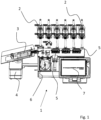
- FIG. 1 shows a system 1 for the production of a medicinal preparation.
- the system 1 for producing a medicinal preparation comprises a large number of source containers 2, which are only partially shown in this view.
- those source containers are not shown in this representation, which contain the main components of the medicinal preparation, as well as the container that is filled with universal liquid.
- these containers can be hung remotely from the system, e.g. on a hook attached to a rail.
- a target container 3 embodied as an infusion bag can be seen, which is arranged on scales 4 .
- the amount of liquid transferred to the target container 3 can be checked via the scales 4 during operation of the system 1 .
- a transfer set which comprises a valve unit 5 and hoses, by means of which the valve unit 5 is connected to the target container 3 on the one hand and to the source containers 2 on the other.
- valve of the valve unit 5 is opened via the system 1 in each dosing step, so that liquid can be pumped from exactly one source container 2 into the target container 3 .
- the system 1 has a single peristaltic pump 6 here, by means of which liquids can be pumped from all the source containers 2 into the target container 3 .
- the system 1 also has a display 7, which is e.g. designed as a touch screen, by means of which the user can program the system 1 and in particular select a program, by means of which a target container 3 is filled with a predetermined composition of components.
- a display 7 which is e.g. designed as a touch screen, by means of which the user can program the system 1 and in particular select a program, by means of which a target container 3 is filled with a predetermined composition of components.
- the system includes an electronic controller (not shown) via which the peristaltic pump 6 is controlled and which is connected to the scale 4 .
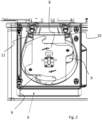
- 2 12 is a detailed view of the peristaltic pump 6. This is preferably provided here as a roller pump.
- the hose pump 6 has a pump wheel 8 with two rollers 9 .
- the hose to be inserted is not shown in this view.
- the method according to the invention can also be carried out using a hose pump with a different number of rollers, in particular using a hose pump which has three rollers (not shown).
- the tube pump has an inlet 10 and an outlet 11 . In the position of the impeller 8 shown here, both rollers 9 are in engagement with the hose.
- rollers 9 move from the outlet 11 to the inlet 10, they are partly disengaged from the hose. This results both on the suction side, ie on the side of the inlet 10, and on the pressure side, ie on the side of the outlet 11, a non-linear characteristic curve of the pump power, the peristaltic pump pulsates.
- the amount of liquid delivered is between 5 and 50 ml per full revolution.
- the peristaltic pump 6 is brought into a position by turning the pump wheel 8 in which the respective micro-amount is completely in the linear range, at least on the suction side the peristaltic pump 6 can be dosed.
- the peristaltic pump includes a rotary encoder (not shown).
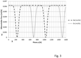
- the pressure-side and suction-side characteristics are in 3 shown.
- phase angle p is divided into 1600 units, which are plotted on the x-axis. These 1600 steps represent one full revolution of the pump.
- the differential flow i.e. the volume delivered per unit of angle of rotation, is plotted on the y-axis for the peristaltic pump.
- the dashed curve represents the differential flow on the pressure side and the dotted curve represents the differential flow on the suction side.
- the characteristic curves are constant over wide areas, i.e. there are areas with a linear characteristic curve.
- the dips are in the areas where a roller comes out of engagement.
- the tubing of the peristaltic pump returns to its original shape.
- the hose increases in volume and the delivery rate of the pump is reduced on the pressure side.
- the pumped volume on the suction side is relevant for the exact dosing, especially of a micro quantity. All liquid that is taken from the source container in the respective dosing step ultimately reaches the target container. It is therefore crucial that the correct volume is removed from the suction side in each dosing step.
- liquid is conveyed in only one of the two linear areas of the suction side of the pump.
- the peristaltic pump is preferably switched to the beginning of the next linear range while pumping universal liquid placed on the suction side.
- the suction-side characteristic of the peristaltic pump is preferably used to more accurately calculate the amount of liquid withdrawn from the source container.
- the characteristic curve on the suction side of the hose pump can also be used for dosing steps that take place in the non-linear range of the hose pump in order to calculate the quantities of liquid removed.
- the calculation takes into account that the suction-side flow rate of the peristaltic pump is not linear.
- p1 is the position of the impeller at the beginning of the dosing step and p2 is the position after the dosing step.
- Vs is the volume to be taken from the source container.
- the pressure-side characteristic curve of the pump can in turn be used to check in an improved way by weighing the target container whether the quantity actually removed corresponds to the calculated quantity.
- the volume of the liquid entering the target container is calculated. Furthermore, the mass of the incoming liquid is calculated based on the known density of the pumped liquid. The characteristic curve Dd of the pressure side is used to determine the volume of the liquid arriving in the target container.
- the characteristic curves which are preferably determined by empirical measurements, can be stored, for example, as approximate formulas or also as a simple table of values, in order to calculate the suction-side and pressure-side pump power as a function of the phase angle.
- the characteristics can be determined by measurement and then approximated by an empirical formula. The calculations in the system are then carried out using the empirical formula or a table of values.
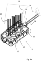
- FIG. 14 is a perspective view of the valve unit 5 used for the medicinal preparation manufacturing plant.
- the valve unit 5 comprises a large number of inlets 12, which are connected to the source containers (2 in 1 ) get connected. Valves (not shown) integrated in the valve unit 5 can selectively connect a hose 15 , by means of which liquid is removed from a source container, to a hose 14 which is arranged on the outlet 13 of the valve unit 5 .
- the hose 14 also has a section which is inserted into the hose pump.
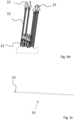
- FIG 4b the ends of the hoses 15 for connecting the source container are shown.
- the connections 22 for the source container can be seen, which in this exemplary embodiment are in the form of a Luer lock connection with an attached spike.
- Figure 4c shows the tube 14, which forms the outlet of the valve unit 5 and at the same time the inlet of the target container. Connection 23 for the target container can be seen.
- valve unit 5 shown here forms, together with the hoses 14, 15 and their connections 22, 23, the transfer set, which is used to operate the system.
- This transfer set is preferably designed as a disposable component and is regularly replaced. Because of this configuration, the liquids to be transferred only come into contact with components of the transfer set on the way from the source container to the target container.
- the transfer set described above is used to connect the source containers.
- a so-called "waste bag” is inserted as a target container, ie a container which is not intended to be used as intended for applying a medicinal preparation, but which is discarded after the system has been prepared.
- the entire transfer set including tubing, is filled with universal fluid (UI), such as isotonic water, and each valve is opened long enough for the tubing (15 in Figure 4a , b ) leading to the source tanks are filled and free of bubbles.
- UI universal fluid
- the dosing factor of the peristaltic pump can be determined by weighing the waste bag when pumping universal liquid.
- the pump capacity of the hose pump which changes due in particular to tolerances in the hose used, is now calibrated by determining this dosing factor.
- the waste bag is then discarded and the first target container, which is to be filled with a medicinal preparation, can be connected.
- a micro-amount is to be dosed in a first dosing step.
- step 5 the impeller is brought into an area with a linear characteristic curve on the suction side, with universal fluid first being conveyed while the impeller is brought into this position.
- a micro-quantity can now be removed from the source container completely in the linear range of the pump's characteristic curve on the suction side.
- Each individual dosing step including the step of dosing a micro-quantity, is checked by weighing the target container.
- the density of the liquid transferred into the target container is taken into account by calculating which liquid or which liquids are in the inlet of the target container when the microquantity is removed in step 5 and are transferred into it.
- a main component of the medicinal preparation is then dosed, taking into account the suction-side characteristic curve of the peristaltic pump.
- the peristaltic pump is also operated in the non-linear range when dosing the main components.
- the suction-side characteristic curve of the peristaltic pump is taken into account in order to be able to precisely predict the volume removed on the suction side.
- the quantity taken from the source container for a main component is also checked, taking into account the density of the liquid transferred to the target container and taking into account the pressure-side characteristic curve of the peristaltic pump.
- a flow factor is preferably included as a further factor in the calculation of the volume of the delivered liquid, which is dependent on the type, in particular the viscosity, of the delivered liquid.
- a flow factor of 1.0 is assigned to water; the flow factor changes significantly in the case of viscous components such as glucose solutions.
- Vs is the volume to be dosed in one dosing step. This corresponds to the volume of the suction side to which a source tank is connected.
- p1 is the position of the impeller before the dosing step, in particular the end position of a previous dosing step or the start of the linear range in which the impeller was previously rotated.
- p2 is the calculated position of the impeller after the dosing step, i.e. the result of the calculation for the rotation angle of the pump in the dosing step.
- F is the flow factor, i.e. the correction factor for the respective viscosity of the medium.
- Ds(p) is the characteristic of the suction side (constant) and p is the phase of the impeller.
- the phases p1 and p2 can differ by several revolutions.
- the flow factor F is therefore a correction for an additional slippage of the pump due to increased viscosity compared to water.
- the volume to be dosed is set higher by a factor of F than with water.
- Vd is the volume expected on the pressure side, i.e. the volume of liquid that is pumped into the target container on the scale during the dosing step.
- Dd(p) is characteristic of the pressure side.
- the flow factor F goes into the calculation of the volume pumped on the pressure side, since the "slip" of the pump is not pumped.
- G Vd ⁇ ⁇ with the density ⁇ of the conveyed medium.
- ⁇ is therefore the specific weight of the liquid transferred into the target container during a dosing step, i.e. initially the liquid that is already present in the inlet of the target container. If several different liquids are transferred to the target container during a dosing step, the specific gravity of the liquids is set in relation to their quantity.
- Steps 5 to 9 can therefore be repeated until all the desired components are in the target container.
- steps 5 to 7, ie the dosing of a micro-amount, and steps 8 and 9, ie the dosing of a main component, are also interchangeable, ie can be carried out in a different order.
- the transfer set is rinsed with universal liquid and, if necessary, the desired residual amount of universal liquid is fed to the target container.
- this rinsing phase in which the impeller of the peristaltic pump rotates more than one full revolution, to re-determine the dosing factor of the peristaltic pump during operation by weighing the target container.
- the dosing factor can thus be recalibrated during operation. This can change, for example, because the elasticity and shape of the hose inserted into the hose pump changes.
- the target container After completing all dosing steps and rinsing the transfer set, the target container can be removed and a new target container connected.
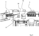
- FIG. 6 is another detail of the 1 .
- the target container 3 can again be seen.
- a valve unit 5 can also be seen.
- the hose not shown here, which connects the valve unit 5 to the target container 3 and which is placed in particular in the hose pump, is first placed in a flow sensor 16 .
- the flow rate in the hose on the suction side is measured via the flow sensor 16 and the delivery capacity of the hose pump can thus be checked for plausibility. If, for example, there is a blockage in the area of the valve unit or at the connection of a source container, the throughflow on the suction side will be reduced to such an extent that an error can be detected by means of the flow sensor 16 . In particular when dosing a micro-amount, the tube will initially also contract in the area of the flow sensor 16, with the result that the detected flow rate is reduced and a blockage can be concluded. An error message can then be generated via the electronic control and displayed to the user.
- the flow sensor 16 is preferably designed as an ultrasonic sensor. In particular at low flow rates, such a sensor is generally not accurate enough to be able to determine the quantity of liquid conveyed on the suction side with sufficient accuracy using the flow sensor alone.
- the flow sensor is therefore preferably used solely for monitoring such that an error is assumed if the difference between the calculated pump capacity of the peristaltic pump and the resulting calculated flow rate compared to the flow rate determined by the flow sensor exceeds a threshold value.
- the hose is placed in a bubble sensor 17 on the pressure side.
- This is an ultrasonic sensor that detects bubbles and switches off the system from a certain threshold value and displays an error to the user.
- FIG. 12 is a schematic representation of the hose 14 connecting the valve unit 5 to the target container 3.
- FIG. 12 In this exemplary embodiment, three valve units connected in series are shown, but this has no effect on the basic principle.
- the three valve units 5 shown here can just as easily be combined into a single valve unit.
- the inlet to a source container is opened by means of the valve unit 5 for each dosing step, so that liquid can flow from the source container via the respective valve of the valve unit first into the valve unit and then into the hose 14 .
- the tube 14 and the collecting channels 22 of the valve units 5 form a volume into which the liquid taken from the respective source containers is initially transferred.
- the calculation of the weight of the liquid which arrives in the target container 3 in a dosing step is therefore not based on the density of the liquid removed in the respective dosing step. Rather, the tube 14 and the collecting channels 24 of the valve unit(s) 5 are considered in such a way that different liquids, namely a first liquid 19, a second liquid 20 and a third liquid 21, are in different sections of the tube 14 and/or the subsequent collecting channel 24 located.
- the specific weight of the first liquid 19 is initially taken as a basis.
- Fig. 12 is a flowchart used to explain verification of each dosing step by weighing the target container.
- the weight transferred to the target container is calculated as a target weight. As described above, this is done on the basis of the pressure-side characteristic curve of the peristaltic pump and the specific gravity of the liquid transferred to the target container.
- the filling process is aborted and an error message appears .
- the user can then correct the error if necessary, insert a waste bag and recalibrate the system.
- the filling process is continued.
- the user of the system receives a message that the system needs to be calibrated.
- next target container can be inserted after the filling process is complete.
- FIG. 12 is a flow chart used to explain the calculation of the target weight in a dosing step.
- the volume of the liquid introduced is calculated using the pressure-side characteristic of the peristaltic pump.
- the target weight can then be calculated from the specific weight of the transferred liquid or liquids.
- This target weight is used to determine the in 8 mentioned limit values.
- a first limit range could be defined as a deviation of more than 10% and a second limit range as a deviation of more than 5%.
- limit ranges can also be varied as a function of the liquid removed during a dosing step, since there are components for which deviations in quantity are more or less critical for the quality of the medicinal preparation.
- Fig. 12 is a flow chart for explaining the bubble sensor control.
- the amount of bubbles in the transferred liquid is continuously monitored by the bubble sensor located after the peristaltic pump.
- the filling process is interrupted and an error message is displayed.
- next target container can be inserted after the filling process is complete
- Fig. 12 is a flowchart for explaining flow sensor control.
- the flow rate is continuously calculated, preferably on the basis of the suction-side characteristic curve of the peristaltic pump.
- the flow rate is measured with a flow sensor arranged on the flow side in front of the peristaltic pump.
- a deviation above a threshold value in this example 20%, an error (e.g. occlusion) is assumed and the filling process is aborted.
- the user is informed of an error message.
- the source container is preferably displayed to the user (e.g. via a number on a screen) in the event of any error message, from which liquid was taken when the error occurred.
- the invention can improve accuracy in manufacturing a medicinal preparation using a tube pump.
Landscapes
- Health & Medical Sciences (AREA)
- Heart & Thoracic Surgery (AREA)
- Urology & Nephrology (AREA)
- Life Sciences & Earth Sciences (AREA)
- Veterinary Medicine (AREA)
- Animal Behavior & Ethology (AREA)
- General Health & Medical Sciences (AREA)
- Public Health (AREA)
- Vascular Medicine (AREA)
- Biomedical Technology (AREA)
- Engineering & Computer Science (AREA)
- Anesthesiology (AREA)
- Hematology (AREA)
- Emergency Medicine (AREA)
- Chemical & Material Sciences (AREA)
- Nutrition Science (AREA)
- Medicinal Chemistry (AREA)
- Pharmacology & Pharmacy (AREA)
- Cardiology (AREA)
- Infusion, Injection, And Reservoir Apparatuses (AREA)
- Pharmaceuticals Containing Other Organic And Inorganic Compounds (AREA)
Description
Die Erfindung betrifft ein Verfahren und eine Anlage zur Herstellung einer medizinischen Zubereitung, wobei eine Schlauchpumpe zum Transferieren von Flüssigkeiten aus Quellbehältern in einen Zielbehälter verwendet wird. insbesondere betrifft die Erfindung ein Verfahren, mittels dessen Infusionsbeutel und/oder Spritzen zur parenteralen Ernährung befüllt werden, sowie eine zugehörige Anlage.The invention relates to a method and a system for producing a medicinal preparation, in which a peristaltic pump is used to transfer liquids from source containers to a target container. In particular, the invention relates to a method by means of which infusion bags and/or syringes for parenteral nutrition are filled, as well as an associated system.
Zubereitungen zur parenteralen Ernährung werden z.B. in Apotheken oder Kliniken patientenspezifisch hergestellt. Es handelt sich dabei um Gemische aus verschiedenen Grundnahrungsstoffen, Spurenelementen und Vitaminen, ggf. auch zusammen mit einem Arzneimittel, die individuell in einen Infusionsbeutel transferiert werden.Preparations for parenteral nutrition are manufactured specifically for the patient, for example in pharmacies or clinics. These are mixtures of different Basic nutrients, trace elements and vitamins, possibly together with a drug, which are transferred individually into an infusion bag.
Hierfür werden sogenannte TPN-Compounder (TPN = Total Parenteral Nutrition) verwendet. Aus der Praxis bekannte und im Markt befindliche Anlagen, wie beispielsweise das System MultiComp® der Firma Fresenius, umfassen eine computergesteuerte Pumpeneinheit, mittels der die Bestandteile der Zusammensetzung aus verschiedenen Quellbehältern in einen auf einer Waage befindlichen Zielbehälter überführt werden.So-called TPN compounders (TPN = Total Parenteral Nutrition) are used for this. Systems known from practice and available on the market, such as the MultiComp® system from Fresenius, include a computer-controlled pump unit, by means of which the components of the composition are transferred from various source containers to a target container on a scale.
Die Anforderungen an die Sicherheit beim Herstellen derartiger medizinischer Zubereitungen sind hoch. insbesondere soll eine hohe Genauigkeit der Dosierung aller Bestandteile sichergestellt sein.The safety requirements when producing such medicinal preparations are high. in particular, a high degree of accuracy in the dosing of all components should be ensured.
Zur Überprüfung der Dosierung kann der Zielbehälter gewogen werden. Ein Compounding-System, in dem der Zielbehälter gewogen wird, ist im Dokument
Problematisch ist, dass die herzustellenden medizinischen Zubereitungen Komponenten mit Hauptbestandteilen wie Wasser, Fett, Zucker und Aminosäuren umfassen, welche in recht großer Menge zugeführt werden. Daneben gibt es Komponenten, die beispielsweise bestimmte Vitamine, Mineralstoffe oder auch ein Arzneimittel umfassen, welche in wesentlicher geringerer Menge, insbesondere im ml-Bereich, zugeführt werden müssen. Derartige Bestandteile werden auch als Mikromengen bezeichnet.The problem is that the medicinal preparations to be produced include components with main constituents such as water, fat, sugar and amino acids, which are supplied in quite large amounts. In addition, there are components that include, for example, certain vitamins, minerals or a drug that must be supplied in significantly smaller amounts, especially in the ml range. Such components are also referred to as microamounts.
Der Erfindung liegt demgegenüber die Aufgabe zugrunde, ein Verfahren zur Herstellung einer medizinischen Zubereitung bereit zu stellen, bei welchem, vorzugsweise mittels einer Schlauchpumpe, eine genaue Dosierung der einzelnen Bestandteile einer medizinischen Zubereitung ermöglicht wird.In contrast, the invention is based on the object of providing a method for producing a medicinal preparation, in which, preferably by means of a peristaltic pump, precise dosing of the individual components of a medicinal preparation is made possible.
Die Aufgabe der Erfindung wird durch ein Verfahren zur Herstellung einer medizinischen Zubereitung nach Anspruch 1 gelöst.The object of the invention is achieved by a method for producing a medicinal preparation according to
Bevorzugte Ausführungsformen und Weiterbildungen der Erfindung sind dem Gegenstand der abhängigen Ansprüche, der Beschreibung sowie den Zeichnungen zu entnehmen.Preferred embodiments and developments of the invention can be found in the subject matter of the dependent claims, the description and the drawings.
Die Erfindung betrifft zunächst ein Verfahren zur Herstellung einer medizinischen Zubereitung. Insbesondere betrifft die Erfindung ein Verfahren zur Herstellung einer Zubereitung zur parenteralen Ernährung.The invention initially relates to a method for producing a medicinal preparation. In particular, the invention relates to a method for producing a preparation for parenteral nutrition.
Dabei werden einer Mehrzahl von Quellbehältern Flüssigkeiten entnommen und in einen Zielbehälter transferiert. Die Herstellung erfolgt automatisiert, wobei der Benutzer der für das Verfahren verwendeten Anlage die im Zielbehälter gewünschte Zusammensetzung eingeben kann oder diese aus einer Datenbank mit einer Mehrzahl von Rezepten auswählen kann.In this case, liquids are removed from a plurality of source containers and transferred to a target container. Production is automated, with the user of the system used for the method being able to enter the composition desired in the target container or to select it from a database with a number of recipes.
Den einzelnen Quellbehältern wird in einer vorgegebenen Reihenfolge jeweils eine definierte Menge Flüssigkeit entnommen, im Folgenden auch als "Dosierschritt" bezeichnet. Nach Abschluss sämtlicher für einen Zielbehälter vorgesehener Dosierschritte ist definitionsgemäß ein "Befüllvorgang" beendet.A defined quantity of liquid is removed from the individual source containers in a predetermined sequence, also referred to below as the "dosing step". After completion of all dosing steps provided for a target container, a "filling process" is finished by definition.
Es kann Bestandteile geben, welche nicht in direkten Kontakt oder nur in einer bestimmten Reihenfolge in Kontakt kommen dürfen.There may be components that are not allowed to come into direct contact or only come into contact in a certain order.
Typischerweise besteht, wie eingangs ausgeführt, eine derartige medizinische Zubereitung aus Hauptbestandteilen, die in größerer Menge zugeführt werden, und sog. "Mikromengen", die insbesondere Vitamine, Mineralstoffe oder Arzneimittelkomponenten enthalten können.As stated at the outset, such a medicinal preparation typically consists of main components that are supplied in relatively large amounts, and so-called "micro-amounts" that can contain, in particular, vitamins, minerals or drug components.
Zum Transferieren wird vorzugsweise ein als Einweg-Bauteil ausgebildetes "Transfer-Set" verwendet, welches den Schlauch umfasst, der in die Schlauchpumpe eingelegt wird. Das Transfer-Set umfasst des Weiteren Anschlussschläuche für die Quellbehälter sowie einen Anschluss für den Zielbehälter. Weiter umfasst das Transfer-Set vorzugsweise eine Ventileinheit, mittels der die Anschlüsse zu den einzelnen Quellbehältern geöffnet und geschlossen werden können.For the transfer, a “transfer set” designed as a disposable component is preferably used, which includes the hose that is inserted into the hose pump. The transfer set also includes connection hoses for the source container and a connection for the target container. Furthermore, the transfer set preferably includes a valve unit, by means of which the connections to the individual source containers can be opened and closed.
Vorzugsweise ist während jedes einzelnen Dosierschritts immer nur ein einziges Ventil, welches zu einem Quellbehälter führt, geöffnet. Es wird also immer nur einem Quellbehälter Flüssigkeit entnommen.Preferably, only a single valve, which leads to a source container, is open during each individual dosing step. Liquid is therefore only ever taken from one source container.
Neben den Hauptbestandteilen der medizinischen Zubereitung und den Mikromengen gibt es bei jeder Zubereitung eine sogenannte universelle Flüssigkeit, auch als "Universal Ingredient" (UI) bezeichnet. Diese Flüssigkeit darf ohne unerwünschte Nebenwirkung mit jeder anderen Zutat in direkten Kontakt kommen und wird in jeder Zubereitung in einer relativ großen Menge verwendet, insbesondere zum Auffüllen der Zubereitung auf die gewünschte Gesamtmenge. Vorzugsweise handelt es sich bei der universellen Flüssigkeit zumeist um isotonisches Wasser.In addition to the main components of the medicinal preparation and the micro-amounts, there is a so-called universal liquid, also known as a "universal ingredient" (UI), in every preparation. This liquid is allowed to come in direct contact with any other ingredient without undesired side effect and is used in any preparation in a relatively large amount, especially to make up the preparation to the desired total amount. Preferably, the universal liquid is mostly isotonic water.
Die für das Verfahren verwendete Schlauchpumpe weist einen Bereich mit linearer Kennlinie und einen Bereich mit nicht linearer Kennlinie auf.The peristaltic pump used for the method has an area with a linear characteristic and an area with a non-linear characteristic.
Unter einem Bereich mit linearer Kennlinie wird der Winkelbereich eines Pumpenrades verstanden, in welchem die Pumpleistung, also das Volumen gegenüber dem Drehwinkel eines Pumpenrades der Schlauchpumpe, konstant ist. Das geförderte Volumen ist zum Drehwinkel der Pumpe proportional.A range with a linear characteristic is understood to mean the angular range of a pump wheel in which the pump output, ie the volume relative to the angle of rotation of a pump wheel of the peristaltic pump, is constant. The pumped volume is proportional to the rotation angle of the pump.
Es gibt einen saugseitig linearen Bereich. Dies ist der Bereich, in welchem eine saugseitige Rolle der Schlauchpumpe in Eingriff mit dem Schlauch ist und keine Rolle neu in den Eingriff mit dem Schlauch geht. Im saugseitig linearen Bereich ist der Drehwinkel zum saugseitig geförderten Volumen proportional.There is a linear area on the intake side. This is the area where a suction-side roller of the peristaltic pump engages the hose and no roller re-engages the hose. In the linear range on the suction side, the angle of rotation is proportional to the volume conveyed on the suction side.
Weiter gibt es einen druckseitig linearen Bereich, in dem der Drehwinkel zum druckseitig geförderten Volumen proportional ist. Die druckseitige Rolle der Schlauchpumpe ist dabei im Eingriff mit dem Schlauch und keine Rolle geht aus dem Eingriff mit dem Schlauch heraus.There is also a linear range on the pressure side, in which the angle of rotation is proportional to the volume conveyed on the pressure side. The pressure-side roller of the peristaltic pump is engaged with the hose and no roller disengages from the hose.
Es versteht sich, dass der druckseitige lineare Bereich der Kennlinie phasenverschoben zu dem saugseitig linearen Bereich der Kennlinie ist.It goes without saying that the pressure-side linear range of the characteristic curve is phase-shifted with respect to the suction-side linear range of the characteristic curve.
Bei einer Schlauchpumpe gehen bei bestimmten Phasenwinkeln die Rollen des Pumpenrades in den Eingriff und bei anderen Phasenwinkeln aus dem Eingriff heraus. Dabei ist zu jedem Zeitpunkt mindestens eine Rolle im Eingriff, die Pumpe ist zu keinem Zeitpunkt "offen". Eine Rollenpumpe hat daher theoretisch keinen Schlupf, also keine Abweichung zwischen Drehwinkel und geförderter Menge.In a peristaltic pump, the rollers of the impeller engage at certain phase angles and disengage at other phase angles. At least one roller is engaged at all times, the pump is not at any Time "open". Theoretically, a roller pump therefore has no slippage, i.e. no deviation between the angle of rotation and the quantity pumped.
Wenn eine Rolle neu in den Eingriff geht, dann verringert sich das Volumen des in die Pumpe eingelegten Schlauchs, wenn eine Rolle aus dem Eingriff herausgeht, vergrößert sich das Volumen wieder. In der Folge ist die Pumpleistung, also das geförderte Volumen pro Drehwinkel, nicht konstant. Die Pumpe "pulsiert". Dieses Pulsieren tritt sowohl an der Saug- als auch an der Druckseite der Pumpe auf.When a role re-engages, the volume of tubing inserted into the pump decreases, when a role disengages, the volume increases again. As a result, the pump performance, i.e. the volume delivered per angle of rotation, is not constant. The pump "pulsates". This pulsation occurs on both the suction and discharge sides of the pump.
Diese nichtlineare Kennlinie sowohl an der Druck- als auch an der Saugseite der Schlauchpumpe ist nachteilig für die Dosiergenauigkeit, was besonders nachteilig ist, wenn mit einer einzigen Schlauchpumpe sowohl Hauptbestandteile in recht großer Menge als auch Mikromengen dosiert werden sollen.This non-linear characteristic both on the pressure side and on the suction side of the peristaltic pump is disadvantageous for the dosing accuracy, which is particularly disadvantageous if both main components in quite large quantities and also micro quantities are to be dosed with a single peristaltic pump.
Gemäß der Erfindung wird die Schlauchpumpe zur Dosierung aus zumindest einem Quellbehälter derart in eine Stellung gebracht, dass die gesamte Dosierung aus diesem Quellbehälter in einem Bereich mit linearer Kennlinie erfolgt.According to the invention, the peristaltic pump for dosing from at least one source container is brought into a position in such a way that the entire dosing from this source container takes place in a range with a linear characteristic.
Der Erfindung liegt die Erkenntnis zugrunde, dass die Dosierung von Mikromengen auch mit einer Schlauchpumpe mit hoher Genauigkeit möglich ist, wenn während des gesamten Dosierschritts die Schlauchpumpe ausschließlich im Bereich mit linearer Kennlinie bewegt wird.The invention is based on the knowledge that the dosing of micro quantities is also possible with a hose pump with high accuracy if the hose pump is moved exclusively in the area with a linear characteristic curve during the entire dosing step.
Es versteht sich, dass hierfür die Menge der bei diesem Dosierschritt zu dosierenden Flüssigkeit derart gering sein muss, dass die gesamte zu dosierende Flüssigkeit in einem Winkelbereich des Pumpenrades der Schlauchpumpe gefördert werden kann, indem dieses den linearen Bereich nicht verlässt.It goes without saying that the quantity of liquid to be metered in this metering step must be so small that the entire liquid to be metered can be conveyed in an angular range of the pump wheel of the peristaltic pump by not leaving the linear range.
Um den Winkel, in welchem ein Pumpenrad der Schlauchpumpe steht, feststellen zu können, umfasst die Schlauchpumpe vorzugsweise einen Drehwinkelgeber.In order to be able to determine the angle at which an impeller of the peristaltic pump is positioned, the peristaltic pump preferably includes a rotary encoder.
Vorzugsweise wird die Schlauchpumpe in eine Stellung gebracht, in welcher die saugseitige Kennlinie der Schlauchpumpe linear ist. Bei der Dosierung von Mikromengen ist vor allem die dem Quellbehälter entnommene Menge an Flüssigkeit entscheidend und es wird daher der saugseitig vorhandene lineare Bereich der Schlauchpumpe verwendet, um die entnommene Menge möglichst exakt zu dosieren.The peristaltic pump is preferably brought into a position in which the suction-side characteristic curve of the peristaltic pump is linear. When dosing micro-amounts, the amount of liquid taken from the source container is particularly important and the linear range of the peristaltic pump available on the suction side is therefore used to dose the amount taken off as precisely as possible.
Um die Schlauchpumpen in die gewünschte Stellung, also den Bereich mit linearer Kennlinie, zu bringen, kann Flüssigkeit aus einem anderen Quellbehälter entnommen werden als aus dem, aus dem dosiert werden soll. Insbesondere kann zum Bewegen des Pumpenrades, beispielsweise an den Anfang des saugseitigen linearen Bereichs, als Quellbehälter ein Quellbehälter mit der vorstehend beschriebenen universellen Flüssigkeit (UI) verwendet werden. Während die Pumpe im nicht linearen Bereich arbeitet, wird also aus dem Quellbehälter mit universeller Flüssigkeit Medium entnommen.In order to bring the peristaltic pumps into the desired position, i.e. the range with a linear characteristic curve, liquid can be taken from a different source container than the one from which dosing is to take place. In particular, a source container with the universal liquid (UI) described above can be used as the source container for moving the impeller, for example to the beginning of the suction-side linear range. While the pump is working in the non-linear range, medium is taken from the source container with universal liquid.
Im Bereich der linearen Kennlinie wird vorzugsweise eine Kleinstmenge mit einem Volumen von unter 10 ml, bevorzugt von unter 5 ml, besonders bevorzugt von kleiner oder gleich 3 ml während eines Dosierschritts gefördert. Es versteht sich, dass die Schlauchpumpe derart dimensioniert sein muss, dass im Bereich der linearen Kennlinie das gesamte zuvor genannte Volumen gefördert werden kann.In the area of the linear characteristic, preferably a very small amount with a volume of less than 10 ml, preferably less than 5 ml, particularly preferably less than or equal to 3 ml, is delivered during a dosing step. It goes without saying that the peristaltic pump must be dimensioned in such a way that the entire aforementioned volume can be conveyed in the area of the linear characteristic curve.
Reicht das während eines einzigen Dosierschritts im linearen Bereich förderbaren Volumen nicht aus, ist es gemäß einer Ausführungsform der Erfindung auch vorgesehen, Flüssigkeit aus einem Quellbehälter in mehreren Dosierschritten zu entnehmen, wobei zwischen diesen einzelnen Dosierschritten die Schlauchpumpe jeweils an den Anfang eines linearen Bereichs gefahren wird.If the volume that can be conveyed in the linear range during a single dosing step is not sufficient, one embodiment of the invention also provides for liquid to be removed from a source container in several dosing steps, with the peristaltic pump being moved to the beginning of a linear range between these individual dosing steps .
In den Dosierschritten, in denen die Hauptbestandteile der medizinischen Zubereitung transferiert werden und bei denen die Dosiergenauigkeit eine weniger große Rolle spielt, kann die Schlauchpumpe in herkömmlicher Weise betrieben werden, also während des jeweiligen Dosierschrittes sowohl der nicht lineare als auch der lineare Bereich der saug- und/oder druckseitigen Kennlinie der Schlauchpumpe durchfahren werden.In the dosing steps in which the main components of the medicinal preparation are transferred and in which the dosing accuracy plays a less important role, the peristaltic pump can be operated in a conventional manner, i.e. during the respective dosing step both the non-linear and the linear range of the suction and/or the pressure-side characteristic curve of the peristaltic pump.
Insbesondere wird in zumindest einem weiteren Dosierschritt eine Menge mit einem Volumen von über 15 ml, vorzugsweise über 20 ml gefördert, wobei die Schlauchpumpe sowohl im Bereich mit linearer Kennlinie als auch in einem Bereich mit nichtlinearer Kennlinie betrieben wird. So werden vorzugsweise die Hauptbestandteile der medizinischen Zubereitung dosiert.In particular, in at least one further dosing step, a quantity with a volume of more than 15 ml, preferably more than 20 ml, is delivered, with the peristaltic pump being operated both in the range with a linear characteristic curve and in a range with a non-linear characteristic curve. This is how the main components of the medicinal preparation are preferably dosed.
Durch die Erfindung kann insbesondere ermöglicht werden, dass sämtliche Dosierschritte beim Herstellen der medizinischen Zubereitung mittels einer einzigen Schlauchpumpe mit hoher Genauigkeit durchgeführt werden.In particular, the invention makes it possible for all dosing steps in the production of the medical preparation to be carried out with great accuracy using a single peristaltic pump.
Bei einer Weiterbildung der Erfindung wird anhand der dem jeweiligen Quellbehälter zu entnehmenden Menge an Flüssigkeit die hierfür erforderliche Drehung des Pumpenrades auf Basis der saugseitigen Kennlinie der Schlauchpumpe berechnet.In a further development of the invention, the amount of liquid to be removed from the respective source container is used to calculate the required rotation of the impeller on the basis of the suction-side characteristic curve of the peristaltic pump.
Über die Drehung der Schlauchpumpe, insbesondere über den Winkel und die Anzahl an Umdrehungen eines Pumpenrades der Schlauchpumpe, kann bei jedem Dosierschritt die dem jeweiligen Quellbehälter entnommene Menge an Flüssigkeit bestimmt werden. Anhand der vorgegebenen zu entnehmenden Menge an Flüssigkeit wird so die Pumpe angesteuert und der erforderliche Drehwinkel für einen Dosierschritt berechnet.The amount of liquid removed from the respective source container can be determined in each dosing step via the rotation of the peristaltic pump, in particular via the angle and the number of revolutions of a pump wheel of the peristaltic pump. Based on the specified amount of liquid to be removed, the pump is controlled and the required angle of rotation for a dosing step is calculated.
Bei der Dosierung und damit bei der Ansteuerung der Schlauchpumpe bei jedem Dosierschritt wird also nicht von einer konstanten Förderleistung ausgegangen, sondern es wird auf Basis einer zuvor bestimmten und gespeicherten Kennlinie die saugseitig vorhandene Schwankung der Pumpleistung einberechnet.When dosing and thus when controlling the peristaltic pump for each dosing step, a constant delivery rate is not assumed, but the fluctuation in the pump capacity on the suction side is calculated on the basis of a previously determined and stored characteristic.
Dies verbessert die Dosiergenauigkeit auch bei Dosierschritten, bei denen die Schlauchpumpe nicht ausschließlich im linearen Bereich betrieben wird.This improves the dosing accuracy even with dosing steps in which the peristaltic pump is not exclusively operated in the linear range.
Vorzugsweise wird bei bzw. nach jedem Dosierschritt der Zielbehälter gewogen und so die Menge der jeweils transferierten Flüssigkeit überprüft.The target container is preferably weighed during or after each dosing step and the quantity of the liquid transferred in each case is checked in this way.
Vorzugsweise wird für diese Überprüfung auf Basis des Gewichts des Zielbehälters aber nicht die berechnete Menge auf Basis der saugseitigen Kennlinie der Schlauchpumpe zugrunde gelegt, sondern es wird unter Berücksichtigung der druckseitigen Kennlinie der Schlauchpumpe berechnet, welche Menge an Flüssigkeit bei Drehung des Pumpenrades um den zuvor berechneten Drehwinkel in den Zielbehälter transferiert wurde.Preferably, this check based on the weight of the target container is not based on the calculated quantity based on the suction-side characteristic of the peristaltic pump, but taking into account the pressure-side characteristic of the peristaltic pump, the amount of liquid when the pump wheel rotates around the previously calculated Angle of rotation has been transferred to the target container.
Stimmt diese berechnete Menge in den Zielbehälter transferierter Flüssigkeit mit dem Ergebnis der Wägung des Zielbehälters überein, so kann der jeweilige Dosierschritt als korrekt betrachtet werden. Stimmen die Ergebnisse dagegen nicht überein bzw. liegen diese außerhalb eines vorgegebenen Toleranzbereiches, kann anlagenseitig ein Fehler, zum Beispiel auf einem Display, angezeigt werden.If this calculated amount of liquid transferred into the target container agrees with the result of the weighing of the target container, then the respective dosing step can be regarded as correct. On the other hand, if the results do not match or are correct If this is outside a specified tolerance range, an error can be displayed on the system side, for example on a display.
Je nach Art und Erheblichkeit des Unterschiedes zwischen berechneter und gewogener Menge kann der Benutzer der Anlage, beispielsweise durch Anzeige auf einem Display, veranlasst werden, den Zielbehält zu verwerfen und einen neuen Zielbehälter zu befüllen und/oder die Anlage zu kalibrieren.Depending on the type and significance of the difference between the calculated and weighed quantity, the user of the system can be prompted, for example by being shown on a display, to discard the target container and to fill a new target container and/or to calibrate the system.
Insbesondere bei der Dosierung von Mikromengen kann es sein, dass nach Entnahme einer vorgegebenen Menge an Flüssigkeit aus einem Quellbehälter die Flüssigkeit nicht unmittelbar in dem Zielbehälter ankommt, sondern sich zunächst im Transfer-Set, beispielsweise im in die Schlauchpumpe eingelegten Schlauch, befindet. Die Flüssigkeit, die sich im Transfer-Set vor dieser Flüssigkeit befindet und die nunmehr in den Zielbehälter gedrückt wird, kann eine andere Dichte haben. Daher kann allein die Gewichtszunahme des Zielbehälters nicht als hinreichend genaues Maß der transferierten Menge verwendet werden.In particular when dosing micro quantities, it may be the case that after removing a specified quantity of liquid from a source container, the liquid does not reach the target container immediately, but is initially in the transfer set, for example in the hose inserted in the peristaltic pump. The liquid that is in front of this liquid in the transfer set and that is now pressed into the target container can have a different density. Therefore, the increase in weight of the target container alone cannot be used as a sufficiently accurate measure of the amount transferred.
Bei einer Ausführungsform der Erfindung wird die Menge der von der Schlauchpumpe geförderten Flüssigkeit berechnet. Es wird bei der Wägung des Zielbehälters die Abfolge und Menge verschiedener Flüssigkeiten im Zulauf des Zielbehälters berücksichtigt, um bei der Überprüfung beim Wiegen die Dichte der Flüssigkeiten mit einzuberechnen.In one embodiment of the invention, the amount of liquid delivered by the peristaltic pump is calculated. When weighing the target container, the sequence and quantity of different liquids in the inlet of the target container are taken into account in order to include the density of the liquids in the check when weighing.
Diese Ausführungsform der Erfindung beruht auf der Erkenntnis, dass die Genauigkeit der Überprüfung bei jedem Dosierschritt erhöht wird, indem die Dichte, also das spezifische Gewicht der jeweiligen in den Zielbehälter transferierten Flüssigkeit, berücksichtigt wird.This embodiment of the invention is based on the finding that the accuracy of the check is increased for each dosing step by taking into account the density, ie the specific weight of the respective liquid transferred into the target container.
Bei dieser Berechnung wird, theoretisch betrachtet, der Zulauf des Zielbehälters in Abschnitte unterteilt, in denen sich jeweils Flüssigkeit mit einer anderen Dichte befindet.From a theoretical point of view, this calculation divides the inlet of the target container into sections, each of which contains liquid with a different density.
Vorzugsweise unter Berücksichtigung der druckseitigen Kennlinie der Schlauchpumpe kann nunmehr vorhergesagt werden, welche Flüssigkeit bzw. Flüssigkeiten bei einem Dosierschritt in den Zielbehälter eingeleitet werden.It is now possible to predict which liquid or liquids will be introduced into the target container during a dosing step, preferably taking into account the pressure-side characteristic curve of the peristaltic pump.
Diesem Prinzip liegt die Betrachtung zugrunde, dass sämtliche den Quellbehältern entnommenen Flüssigkeiten letztendlich im Zielbehälter ankommen. Da das Volumen der Strecke vom Quellbehälter bzw. vom Ventil, ab dem die Flüssigkeit des jeweiligen Quellbehälters in die Ventileinheit fließt, bis zum auf der Waage befindlichen Quellbehälter bekannt ist, kann berechnet werden, welche Flüssigkeit oder welche Flüssigkeiten bei einem Dosierschritt im Zielbehälter ankommt oder ankommen.This principle is based on the consideration that all liquids taken from the source containers ultimately arrive in the target container. Since the volume of the route from the source container or from the valve, from which the liquid from the respective source container flows into the valve unit, to the source container on the scale is known, it can be calculated which liquid or which liquids arrives in the target container during a dosing step or arrive.
Das Volumen wird durch die Ventileinheit ab der Position des jeweiligen Ventils des Quellbehälters sowie durch den durch die Schlauchpumpe geführten Schlauch bestimmt, der die Ventileinheit mit dem Zielbehälter verbindet.The volume is determined by the valve assembly from the position of each valve of the source container and by the tubing routed through the peristaltic pump that connects the valve assembly to the destination container.
Bei der Überprüfung des jeweiligen Dosierschritts durch Wägung des Zielbehälters wird daher nicht die Dichte der bei dem jeweiligen Dosierschritt entnommenen Flüssigkeit zugrunde gelegt, sondern die Dichte der Flüssigkeit oder der Flüssigkeiten, die in den Zielbehälter eingeleitet werden. Die Dichte der eingeleiteten Flüssigkeit kann sich aufgrund des Volumens des Zulaufes und der Schlauchpumpe zumindest am Anfang des Dosierschritts unterscheiden.When checking the respective dosing step by weighing the target container, the density of the liquid removed in the respective dosing step is not used as a basis, but rather the density of the liquid or liquids that are introduced into the target container. The density of the liquid introduced can differ due to the volume of the feed and the peristaltic pump, at least at the beginning of the dosing step.
Es versteht sich, dass die in einem Zulauf und/oder in einem Schlauch der Schlauchpumpe angeordneten Flüssigkeiten nicht exakt entsprechend dieses Berechnungsmodels voneinander separiert sind, sondern sich verschiedene Flüssigkeiten im Bereich der Grenzfläche vermischen. Es hat sich aber gezeigt, dass diese Vermischungseffekte im Allgemeinen oder in einer Näherung vernachlässigt werden können.It goes without saying that the liquids arranged in an inlet and/or in a hose of the hose pump are not separated from one another exactly according to this calculation model, but different liquids mix in the area of the interface. However, it has been shown that these mixing effects can be neglected in general or as an approximation.
Bei einer Ausführungsform der Erfindung wird der Zielbehälter bei jedem einzelnen Dosierschritt gewogen und so die Menge der in den Zielbehälter transferierten Flüssigkeit bei jedem einzelnen Dosierschritt überprüft.In one embodiment of the invention, the target container is weighed at each individual dosing step and the amount of liquid transferred into the target container is thus checked at each individual dosing step.
Eine Überprüfung jedes einzelnen Dosierschritts wird vorzugsweise auch bei Mikromengen dadurch ermöglicht, dass die Menge der bei einem Dosierschritt in den Zielbehälter transferierten Flüssigkeit unter Berücksichtigung der druckseitigen Kennlinie der Schlauchpumpe berechnet wird.A check of each individual dosing step is preferably made possible, even with micro quantities, by the amount of liquid transferred into the target container during a dosing step being calculated, taking into account the pressure-side characteristic of the peristaltic pump.
Bei herkömmlichen Anlagen zur Zubereitung parenteraler Ernährung kann mit einer genau arbeitenden Wägezelle zwar am Ende des Befüllvorgangs, also nach Abschluss sämtlicher Dosierschritte, überprüft werden, ob die Gewichtszunahme des Zielbehälters mit der zu dosierenden Sollmenge der Einzelbestandteile übereinstimmt.With conventional systems for the preparation of parenteral nutrition, a precisely working load cell can be used at the end of the filling process, i.e. after completion of all dosing steps, whether the increase in weight of the target container corresponds to the target quantity of the individual components to be dosed.
Zumindest bei Mikromengen ist jedoch eine hinreichend genaue Beurteilung jedes einzelnen Dosierschritts aufgrund der druckseitig nicht linearen Kennlinie grundsätzlich nicht möglich.However, at least in the case of micro quantities, a sufficiently precise assessment of each individual dosing step is fundamentally not possible due to the non-linear characteristic curve on the pressure side.
Durch die Berücksichtigung der druckseitigen Kennlinie und/oder durch den Betrieb der Schlauchpumpe im linearen Bereich bei der Dosierung von Mikromengen kann dagegen eine Überprüfung des einzelnen Dosierschritts durch Wiegen des Zielbehälters, insbesondere auch bei Mikromengen, vorgenommen werden.By taking into account the pressure-side characteristic and/or by operating the peristaltic pump in the linear range when dosing micro quantities, on the other hand, the individual dosing step can be checked by weighing the target container, especially with micro quantities.
Hierdurch wird die Sicherheit, dass die Zusammensetzung der medizinischen Zubereitung den Vorgaben entspricht, erhöht.This increases the certainty that the composition of the medicinal preparation corresponds to the specifications.
Bei der Dosierung von Mikromengen kann es zudem zu Okklusionen kommen, die anlagenseitig schwer zu erfassend sind. Sofern beispielsweise der von einem Quellbehälter zur Schlauchpumpe führende Schlauch verstopft ist, fördert bei einer geringen Menge, insbesondere bei einer Menge von unter 3 ml, die Schlauchpumpe dennoch Flüssigkeit in den Zielbehälter, da sich die flexiblen Schläuche des Transfer-Sets zusammenziehen können. Wird nunmehr im Anschluss das Ventil zu einem anderen Quellbehälter geöffnet, so entspannt sich der Schlauch, indem dieser Flüssigkeit aus dem anderen Quellbehälter ansaugt.When dosing micro quantities, occlusions can also occur, which are difficult to detect on the plant side. If, for example, the tubing leading from a source container to the peristaltic pump is blocked, the peristaltic pump will still deliver liquid to the target container if the volume is small, especially if the volume is less than 3 ml, as the flexible tubes of the transfer set can contract. If the valve to another source container is then opened, the hose relaxes by sucking in liquid from the other source container.
Dieser Effekt kann unter Umständen dazu führen, dass am Ende aller Dosierschritte die mit dem Wiegen des Zielbehälters überprüfte Gesamtmenge stimmt, eine einzelne Mikromenge aber in völlig falscher Dosierung oder gar nicht vorliegt.Under certain circumstances, this effect can mean that at the end of all dosing steps, the total quantity checked by weighing the target container is correct, but a single micro quantity is completely wrong or not available at all.
Bei einer Weiterbildung der Erfindung wird daher mittels eines Flusssensors die Förderleistung der Schlauchpumpe überprüft. Vorzugsweise ist der Flusssensor saugseitig angeordnet. Es kann insbesondere ein Flusssensor vorgesehen sein, in welchen ein Schlauch des Transfer-Sets eingelegt wird.In a further development of the invention, the flow rate of the peristaltic pump is therefore checked by means of a flow sensor. The flow sensor is preferably arranged on the suction side. In particular, a flow sensor can be provided, into which a tube of the transfer set is inserted.
Derartige Flusssensoren sind bekannt. Es hat sich herausgestellt, dass sich diese aber nicht eignen, um die Durchflussmenge auch bei sehr niedriger Fließgeschwindigkeit exakt zu bestimmen.Such flow sensors are known. However, it has been found that these are not suitable for precisely determining the flow rate even at very low flow rates.
Im Falle einer Verstopfung oder im Falle eines sich nicht öffnenden Ventils des Transfer-Sets kann über den Flusssensor aber eine derart hohe Abweichung von einem Sollwert festgestellt werden, dass daraus geschlossen werden kann, dass die Durchflussmenge zur gegenwärtigen theoretischen Förderleistung der Pumpe nicht plausibel ist.In the event of a blockage or if the transfer set valve does not open, the flow sensor can detect such a high deviation from a setpoint that it can be concluded that the flow rate is not plausible in relation to the current theoretical delivery rate of the pump.
Das Verfahren kann sodann abgebrochen werden und der Benutzer der Anlage über eine Fehlermeldung informiert werden.The method can then be aborted and the user of the system can be informed of an error message.
Bei einer Weiterbildung der Erfindung wird ein Blasensensor (Bubbel-Detector) verwendet, um in einem Zulauf im Zielbehälter zu überprüfen, dass keine Blasen im Schlauch gefördert werden.In a development of the invention, a bubble sensor (bubble detector) is used to check in an inlet in the target container that no bubbles are being conveyed in the hose.
Dieser Blasensensor, welcher beispielsweise als Ultraschall-Sensor ausgebildet sein kann, befindet sich vorzugsweise druckseitig zur Schlauchpumpe. Es handelt sich insbesondere um einen Sensor, in welchen der Schlauch eines Transfer-Sets eingelegt werden kann.This bubble sensor, which can be designed as an ultrasonic sensor, for example, is preferably located on the pressure side of the hose pump. In particular, it is a sensor into which the tubing of a transfer set can be inserted.
Im Falle des Vorhandenseins von Blasen über einem Schwellwert kann ebenfalls das Verfahren gestoppt und der Benutzer mittels einer Fehlermeldung informiert werden.In the event of the presence of bubbles above a threshold value, the method can also be stopped and the user informed by means of an error message.
Bei einer bevorzugten Ausführungsform der Erfindung wird der Dosierfaktor der Schlauchpumpe in einem vorgeschalteten Kalibrierschritt mittels Wiegen eines Zielbehälters bestimmt.In a preferred embodiment of the invention, the dosing factor of the peristaltic pump is determined in a preceding calibration step by weighing a target container.
Der Dosierfaktor ist das Volumen, welches bei Förderung einer bestimmten Flüssigkeit, insbesondere bei Förderung von Wasser, bei einer bestimmten Geschwindigkeit des Pumpenrades und bei einer vollen Pumpenumdrehung gefördert wird. Der Dosierfaktor hängt unter anderem von Toleranzen des in die Pumpe eingelegten Schlauchs ab. Dieser Dosierfaktor kann bei Inbetriebnahme der Anlage beim Befüllen eines Zielbehälters kalibriert werden, um die Ansteuerung der Schlauchpumpe einem neu verwendeten Transfer-Set anzupassen.The dosing factor is the volume that is pumped when pumping a specific liquid, in particular when pumping water, at a specific speed of the impeller and at one full pump revolution. The dosing factor depends, among other things, on the tolerances of the hose inserted in the pump. This dosing factor can be calibrated when the system is started up when a target container is filled, in order to adapt the control of the peristaltic pump to a newly used transfer set.
Es ist insbesondere vorgesehen, dass bei Inbetriebnahme der Anlage zur Herstellung der medizinischen Zubereitung ein erster Zielbehälter verwendet wird, welcher im Anschluss verworfen wird, ein sogenannter "waste bag". Dieser waste bag ("Abfallbehälter") wird mittels des Transfer-Sets angeschlossen und es werden die zu sämtlichen Quellbehältern führenden Schläuche entlüftet, indem jeweils eine hierfür erforderliche Menge an Flüssigkeit entnommen wird.In particular, it is provided that when the system is started up for the production of the medical preparation, a first target container is used, which is then discarded, a so-called "waste bag". This waste bag ("waste container") is connected using the transfer set and the to all hoses leading to the source containers are vented by removing the amount of liquid required for this purpose.
Zur Bestimmung des Dosierfaktors kann Flüssigkeit, vorzugsweise Wasser, in den waste bag gefördert und dabei der Dosierfaktor bestimmt werden. Nach Verwerfen des waste bag wird nunmehr dieser Dosierfaktor für die Berechnung der von der Pumpe bei weiteren Dosierschritten geförderten Menge zugrunde gelegt.To determine the dosing factor, liquid, preferably water, can be pumped into the waste bag and the dosing factor can be determined in the process. After discarding the waste bag, this dosing factor is now used as a basis for calculating the quantity delivered by the pump in further dosing steps.
Es versteht sich, dass der Dosierfaktor wiederum mit der vorstehend beschriebenen Berücksichtigung des nicht linearen Bereichs der saugseitigen und druckseitigen Kennlinie der Schlauchpumpe ins Verhältnis zu setzen ist.It goes without saying that the dosing factor is in turn to be set in relation to the above-described consideration of the non-linear range of the suction-side and pressure-side characteristic of the peristaltic pump.
Weiter hängt die Pumpleistung einer Schlauchpumpe unter anderem auch vom zu fördernden Medium, insbesondere von der Viskosität der zu fördernden Flüssigkeit, ab. Diese Abhängigkeit kann, wie es bei einer Ausführungsform der Erfindung vorgesehen ist, ebenfalls bei der Berechnung der geförderten Mengen berücksichtigt werden.Furthermore, the pump performance of a peristaltic pump also depends, among other things, on the medium to be pumped, in particular on the viscosity of the liquid to be pumped. As provided in one embodiment of the invention, this dependency can also be taken into account when calculating the conveyed quantities.
Bei Wasser kann ein Flussfaktor von 1,0 angesetzt werden. Bei anderen Medien, wie beispielsweise Glukose, nimmt dieser Flussfaktor höhere Werte, beispielsweise Werte bis 1,1 an. Dies kann bei der Berechnung der geförderten Mengen, insbesondere der geförderten Mengen an Hauptbestandteilen, berücksichtigt werden, indem der Flussfaktor in die Berechnung des geförderten Volumens mit eingeht.A flow factor of 1.0 can be used for water. With other media, such as glucose, this flow factor assumes higher values, for example values up to 1.1. This can be taken into account when calculating the conveyed quantities, in particular the conveyed quantities of main components, by including the flow factor in the calculation of the conveyed volume.
Bei einer Weiterbildung der Erfindung wird während der Herstellung der medizinischen Zubereitung dann, wenn sich ein Pumpenrad der Schlauchpumpe zumindest eine volle Umdrehung dreht, der Dosierfaktor der Schlauchpumpe kalibriert, vorzugsweise mit Ul.In a further development of the invention, the dosing factor of the hose pump is calibrated, preferably with Ul.
Der Dosierfaktor der Schlauchpumpe wird also nicht nur initial bei Inbetriebnahme der Anlage bestimmt, sondern wird, wenn dies möglich ist, auch während des regulären Betriebs der Anlage, also beim Herstellen von medizinischen Zubereitungen der Dosierfaktor überprüft und ggf. neu kalibriert.The dosing factor of the peristaltic pump is not only determined initially when the system is started up, but is also checked and recalibrated if necessary during regular operation of the system, i.e. when producing medicinal preparations.
Es ist insbesondere vorgesehen, dass es neben einem initialen Kalibrieren durch Bestimmen des Dosierfaktors mehrere, vorzugsweise zumindest drei, weitere Bestimmungen des Dosierfaktors während der Einsatzdauer eines Transfer-Sets gibt.In particular, it is provided that, in addition to an initial calibration by determining the dosing factor, there are several, preferably at least three, further determinations of the dosing factor during the period of use of a transfer set.
Vorzugsweise wird diese Kalibrierung im laufenden Betrieb dann durchgeführt, wenn eine hinreichende Menge universeller Flüssigkeit oder Wasser in den Zielbehälter transferiert wird, da der Flussfaktor dieser universellen Flüssigkeit immer 1,0 beträgt, so dass kein Fehler aufgrund eines unterschiedlichen Flussfaktors in die Kalibrierung eingeht. Die Kalibrierung im laufenden Betrieb erfolgt vorzugsweise bei Förderung derselben Flüssigkeit, wie diese zum initialen Bestimmen des Dosierfaktors unter Verwendung des waste bag verwendet wurde.Preferably, this on-line calibration is performed when a sufficient quantity of universal liquid or water is transferred to the target container, since the flow factor of this universal liquid is always 1.0, so that no flow factor variation error is introduced into the calibration. The calibration during operation is preferably carried out when the same liquid is pumped as was used to initially determine the dosing factor using the waste bag.
Besonders bevorzugt wird die Kalibrierung im laufenden Betrieb erst vorgenommen, wenn das Transfer-Set mit universeller Flüssigkeit gespült ist, der Zulauf des Zielbehälters also keine Abschnitte aufweist, in welchen sich eine andere Flüssigkeit befindet.The calibration is particularly preferably only carried out during operation when the transfer set has been rinsed with a universal liquid, ie the inlet of the target container does not have any sections in which there is another liquid.
Da so während der gesamten Kalibrierung nur Flüssigkeit mit gleicher Dichte und gleicher Viskosität gefördert wird, wird eine höhere Genauigkeit beim Kalibrieren erreicht.Since only liquid with the same density and the same viscosity is pumped during the entire calibration, greater accuracy is achieved during calibration.
Die vorab beschriebenen erfindungsgemäßen Verfahrensschritte können umgesetzt werden durch Einrichtungen, die entsprechend ausgebildet oder geeignet sind zum Ausführen der beschriebenen Verfahrensschritte. Diese Einrichtungen können Bestandteil eines Systems sein.The method steps according to the invention described above can be implemented by devices that are appropriately designed or suitable for carrying out the method steps described. These devices can be part of a system.
Im Bereich der Erfindung liegt daher auch eine Anlage zur Herstellung einer medizinischen Zubereitung, insbesondere eine Anlage zur Herstellung von Parenteralnahrung, umfassend eine Schlauchpumpe und ein System zum Ausführen eines Verfahrens gemäß der vorstehend beschriebenen Erfindung.The scope of the invention therefore also includes a system for producing a medicinal preparation, in particular a system for producing parenteral food, comprising a peristaltic pump and a system for carrying out a method according to the invention described above.
Das erfindungsgemäße Verfahren ist insbesondere ausführbar mittels der erfindungsgemäßen Anlage. Die Anlage mit dem erfindungsgemäßen System ist insbesondere ausgebildet zur Ausführung des erfindungsgemäßen Verfahrens.The method according to the invention can be carried out in particular by means of the system according to the invention. The plant with the system according to the invention is designed in particular to carry out the method according to the invention.
Der Gegenstand der Erfindung soll im Folgenden, Bezug nehmend auf die Zeichnungen
-
Fig. 1 zeigt eine perspektivische Ansicht einer Anlage zur Herstellung einer medizinischen Zubereitung, wie sie für das erfindungsgemäße Verfahren verwendet wird. -
Fig. 2 ist eine Detailansicht der Schlauchpumpe. - Bezugnehmend auf
Fig. 3 soll die Kennlinie einer Schlauchpumpe anhand eines Ausführungsbeispiels erläutert werden. -
Fig. 4a bis 4c sind Detailansichten der Ventileinheit der Anlage zur Herstellung einer medizinischen Zubereitung mit deren Schläuchen. -
Fig. 5a undFig. 5b zeigen anhand eines Flussdiagramms die Verfahrensschritte bei einem Ausführungsbeispiel des erfindungsgemäßen Verfahrens. -
Fig. 6 ist eine Detailansicht der Anlage zur Herstellung einer medizinischen Zubereitung, in welcher Flusssensor und Blasensensor zu erkennen sind. -
Fig. 7 ist eine schematische Darstellung des Zulaufs des Zielbehälters, anhand welcher die Berechnung der in den Zielbehälter transferierten Menge erläutert wird. -
Fig. 8 ist ein Flussdiagramm, anhand dessen die Überprüfung jedes Dosierschrittes durch Wiegen des Zielbehälters erläutert wird. -
Fig. 9 ist ein Flussdiagramm, anhand dessen die Berechnung des Gewichts der in den Zielbehälter transferierten Flüssigkeit erläutert wird. -
Fig. 10 ist ein Flussdiagramm, anhand dessen die Kontrolle über den Blasensensor erläutert werden soll. -
Fig. 11 ist ein Flussdiagramm, anhand dessen die Kontrolle über den Flusssensor erläutert werden soll.
-
1 shows a perspective view of a plant for the production of a medicinal preparation as used for the method according to the invention. -
2 is a detailed view of the peristaltic pump. - Referring to
3 the characteristic curve of a peristaltic pump is to be explained using an exemplary embodiment. -
Figures 4a to 4c are detailed views of the valve unit of the plant for the production of a medicinal preparation with its hoses. -
Figure 5a andFigure 5b use a flow chart to show the method steps in an exemplary embodiment of the method according to the invention. -
6 is a detailed view of the plant for the production of a medicinal preparation, in which flow sensor and bubble sensor can be seen. -
Figure 7 is a schematic representation of the inflow of the target container, on the basis of which the calculation of the quantity transferred into the target container is explained. -
8 Fig. 12 is a flowchart used to explain verification of each dosing step by weighing the target container. -
9 Fig. 12 is a flow chart for explaining the calculation of the weight of the liquid transferred to the target container. -
10 Fig. 12 is a flow chart for explaining the bubble sensor control. -
11 Fig. 12 is a flowchart for explaining flow sensor control.
Die Anlage 1 zur Herstellung einer medizinischen Zubereitung umfasst eine Vielzahl von Quellbehältern 2, welche in dieser Ansicht nur teilweise dargestellt sind. Insbesondere sind in dieser Darstellung diejenigen Quellbehälter nicht dargestellt, welche die Hauptbestandteile der medizinischen Zubereitung umfassen, sowie derjenige Behälter, der mit universeller Flüssigkeit gefüllt ist. Diese Behälter können insbesondere anlagenfern, z.B. an einem an einer Schiene befestigten Haken, aufgehängt werden.The
Zu erkennen ist ein als Infusionsbeutel ausgebildeter Zielbehälter 3, welcher auf einer Waage 4 angeordnet ist. Über die Waage 4 kann während des Betriebs der Anlage 1 die Menge der in den Zielbehälter 3 transferierten Flüssigkeit überprüft werden.A
Um die Anlage 1 in Betrieb zu nehmen, wird ein Transfer-Set verwendet, welches eine Ventileinheit 5 sowie Schläuche umfasst, mittels der die Ventileinheit 5 zum einen mit dem Zielbehälter 3 und zum anderen mit den Quellbehältern 2 verbunden wird.In order to put the
Beim Herstellen einer medizinischen Zubereitung wird über die Anlage 1 jeweils bei einem Dosierschritt ein Ventil der Ventileinheit 5 geöffnet, so dass Flüssigkeit von genau einem Quellbehälter 2 in den Zielbehälter 3 gepumpt werden kann.When producing a medicinal preparation, a valve of the
Um die Flüssigkeiten zu fördern, weist die Anlage 1 hier eine einzige Schlauchpumpe 6 auf, mittels welcher Flüssigkeiten aus sämtlichen Quellbehältern 2 in den Zielbehälter 3 gepumpt werden können.In order to convey the liquids, the
Die Anlage 1 weist ferner ein Display 7 auf, welches z.B. als Touch-Screen ausgebildet ist, mittels welchem der Benutzer die Anlage 1 programmieren und insbesondere ein Programm auswählen kann, mittels dessen ein Zielbehälter 3 mit einer vorgegebenen Zusammensetzung von Bestandteilen befüllt wird.The
Die Anlage umfasst eine elektronische Steuerung (nicht dargestellt), über die die Schlauchpumpe 6 angesteuert wird und die mit der Waage 4 verbunden ist.The system includes an electronic controller (not shown) via which the
Zu erkennen ist, dass die Schlauchpumpe 6 ein Pumpenrad 8 mit zwei Rollen 9 aufweist. Der einzulegende Schlauch ist in dieser Ansicht nicht dargestellt.It can be seen that the
Es versteht sich, dass das erfindungsgemäße Verfahren auch mit einer Schlauchpumpe mit einer anderen Anzahl an Rollen ausgeführt werden kann, insbesondere mit einer Schlauchpumpe, die drei Rollen umfasst (nicht dargestellt).It goes without saying that the method according to the invention can also be carried out using a hose pump with a different number of rollers, in particular using a hose pump which has three rollers (not shown).
Wird ein Schlauch (nicht dargestellt) in die Schlauchpumpe 6 eingelegt, so weist die Schlauchpumpe einen Einlass 10 und einen Auslass 11 auf. In der hier dargestellten Stellung des Pumpenrads 8 sind beide Rollen 9 im Eingriff mit dem Schlauch.If a tube (not shown) is inserted into the
Es versteht sich aber, dass, wenn die Rollen 9 sich vom Auslass 11 zum Einlass 10 bewegen, diese teils nicht im Eingriff mit dem Schlauch sind. Hieraus resultiert sowohl saugseitig, also auf Seite des Einlasses 10, als auch druckseitig, also auf Seite des Auslasses 11, eine nicht lineare Kennlinie der Pumpleistung, die Schlauchpumpe pulsiert.However, it is understood that when the
Vorzugsweise beträgt die Menge der geförderten Flüssigkeit bei einer vollen Umdrehung zwischen 5 und 50 ml.Preferably, the amount of liquid delivered is between 5 and 50 ml per full revolution.
Um auch Mikromengen, also Mengen, die im unteren ml-Bereich liegen, exakt dosieren zu können, wird gemäß einem Aspekt der Erfindung die Schlauchpumpe 6 durch Drehen des Pumpenrads 8 in eine Stellung verbracht, in welcher die jeweilige Mikromenge vollständig im zumindest saugseitig linearen Bereich der Schlauchpumpe 6 dosiert werden kann.In order to be able to precisely dose micro-amounts, i.e. amounts in the lower ml range, according to one aspect of the invention, the
Hierzu umfasst die Schlauchpumpe einen Drehwinkelgeber (nicht dargestellt).For this purpose, the peristaltic pump includes a rotary encoder (not shown).
In der hier darstellten Stellung des Pumpenrads 8 ist eine Rolle 9 gerade an dem Einlass 10 vorbeigestrichen und nunmehr im Eingriff mit dem eingelegten Schlauch.In the position of the
Es bietet sich an, die Schlauchpumpe 6 zur Dosierung einer Mikromenge in die hier dargestellte Stellung zu bringen, um sodann die Mikromenge vollständig im Bereich der saugseitig linearen Kennlinie der Schlauchpumpe 6 dosieren zu können.It makes sense to bring the
Die druckseitige und saugseitige Kennlinie ist in
Der Phasenwinkel p ist in 1600 Einheiten eingeteilt, welche auf der x-Achse aufgetragen sind. Diese 1600 Schritte stellen eine volle Umdrehung der Pumpe dar.The phase angle p is divided into 1600 units, which are plotted on the x-axis. These 1600 steps represent one full revolution of the pump.
Auf der y-Achse ist der differentielle Fluss, also das geförderte Volumen pro Drehwinkel-Einheit, für die Schlauchpumpe aufgetragen.The differential flow, i.e. the volume delivered per unit of angle of rotation, is plotted on the y-axis for the peristaltic pump.
Die gestrichelte Kennlinie stellt den druckseitigen differentiellen Fluss und die gepunktete Kennlinie den saugseitigen differentiellen Fluss dar.The dashed curve represents the differential flow on the pressure side and the dotted curve represents the differential flow on the suction side.
Zu erkennen ist, dass die Kennlinien über weite Bereiche konstant verlaufen, also Bereiche mit linearer Kennlinie vorhanden sind.It can be seen that the characteristic curves are constant over wide areas, i.e. there are areas with a linear characteristic curve.
Jede Kennlinie weist allerdings zwei Einbrüche auf. Auf der Saugseite sind das die Phasenwinkel, bei denen eine der zwei Rollen neu in Eingriff geht (p=700 und p=1500). In diesen Bereichen wird das Volumen des Schlauches der Schlauchpumpe in der Nähe des saugseitigen Anschlusses verkleinert. Die Saugleistung der Pumpe ist reduziert.However, each characteristic shows two dips. On the suction side, these are the phase angles at which one of the two rollers re-engages (p=700 and p=1500). In these areas, the volume of the hose of the peristaltic pump is reduced in the vicinity of the suction-side connection. The suction power of the pump is reduced.
Auf der Druckseite liegen die Einbrüche in den Bereichen, an denen eine Rolle aus dem Eingriff herausgeht. Dabei kehrt der Schlauch der Schlauchpumpe in seine ursprüngliche Form zurück. Der Schlauch vergrößert sein Volumen und die Förderrate der Pumpe ist druckseitig reduziert.On the pressure side, the dips are in the areas where a roller comes out of engagement. The tubing of the peristaltic pump returns to its original shape. The hose increases in volume and the delivery rate of the pump is reduced on the pressure side.
Für die exakte Dosierung, insbesondere einer Mikromenge, ist das geförderte Volumen der Saugseite relevant. Sämtliche Flüssigkeit, die im jeweiligen Dosierschritt dem Quellbehälter entnommen wird, gelangt letztendlich in den Zielbehälter. Es ist daher entscheidend, dass in jedem Dosierschritt das korrekte Volumen saugseitig entnommen wird.The pumped volume on the suction side is relevant for the exact dosing, especially of a micro quantity. All liquid that is taken from the source container in the respective dosing step ultimately reaches the target container. It is therefore crucial that the correct volume is removed from the suction side in each dosing step.
Bei Dosierung einer sogenannten Mikromenge wird nunmehr gemäß der Erfindung bei einem Dosierschritt Flüssigkeit nur in einem der zwei linearen Bereiche der Saugseite der Pumpe gefördert.When dosing a so-called micro-amount, according to the invention, in a dosing step, liquid is conveyed in only one of the two linear areas of the suction side of the pump.
Hierfür wird die Schlauchpumpe vor Beginn des Dosierschrittes unter Pumpen universeller Flüssigkeit vorzugsweise auf den Anfang des nächsten linearen Bereiches der Saugseite gestellt. In diesem Beispiel liegen diese Positionen etwa bei p=50 und p=850.For this purpose, before beginning the dosing step, the peristaltic pump is preferably switched to the beginning of the next linear range while pumping universal liquid placed on the suction side. In this example, these positions are around p=50 and p=850.
So lassen sich mit einer einzigen Schlauchpumpe auch Mikromengen exakt dosieren.In this way, even micro quantities can be precisely dosed with a single peristaltic pump.
Die saugseitige Kennlinie der Schlauchpumpe wird vorzugsweisedazu verwendet, die Menge der dem Quellbehälter entnommenen Flüssigkeit exakter zu berechnen.The suction-side characteristic of the peristaltic pump is preferably used to more accurately calculate the amount of liquid withdrawn from the source container.
So lässt sich auch bei Dosierschritten, die im nicht linearen Bereich der Schlauchpumpe stattfinden, die saugseitige Kennlinie der Schlauchpumpe heranziehen, um die Mengen der entnommenen Flüssigkeit zu berechnen.In this way, the characteristic curve on the suction side of the hose pump can also be used for dosing steps that take place in the non-linear range of the hose pump in order to calculate the quantities of liquid removed.
Es wird also bei der Berechnung berücksichtigt, dass die saugseitige Fördermenge der Schlauchpumpe nicht linear ist.The calculation takes into account that the suction-side flow rate of the peristaltic pump is not linear.
Anhand der Kennlinie Ds wird der Phasenwinkel p2 bestimmt, so dass ![]()
![]()
Die druckseitige Kennlinie der Pumpe kann wiederum verwendet werden, um in verbesserter Weise durch Wägung des Zielbehälters zu überprüfen, ob die tatsächlich entnommene Menge der berechneten Menge entspricht.The pressure-side characteristic curve of the pump can in turn be used to check in an improved way by weighing the target container whether the quantity actually removed corresponds to the calculated quantity.
Hierzu wird das Volumen der in den Zielbehälter eintreffenden Flüssigkeit berechnet. Weiter wird anhand der bekannten Dichte der geförderten Flüssigkeit die Masse der eintreffenden Flüssigkeit berechnet. Zur Bestimmung des Volumens der im Zielbehälter eintreffenden Flüssigkeit wird die Kennlinie Dd der Druckseite verwendet.To do this, the volume of the liquid entering the target container is calculated. Furthermore, the mass of the incoming liquid is calculated based on the known density of the pumped liquid. The characteristic curve Dd of the pressure side is used to determine the volume of the liquid arriving in the target container.
Die vorzugsweise durch empirische Messungen bestimmten Kennlinien können z.B. als angenäherte Formeln oder auch als einfache Wertetabelle gespeichert werden, um die saugseitige und druckseitige Pumpleistung in Abhängigkeit vom Phasenwinkel zu berechnen. Insbesondere können die Kennlinien durch Messung bestimmt und dann durch eine empirische Formel angenähert werden. Die Berechnungen in der Anlage erfolgen dann mittels der empirischen Formel oder über eine Wertetabelle.The characteristic curves, which are preferably determined by empirical measurements, can be stored, for example, as approximate formulas or also as a simple table of values, in order to calculate the suction-side and pressure-side pump power as a function of the phase angle. In particular, the characteristics can be determined by measurement and then approximated by an empirical formula. The calculations in the system are then carried out using the empirical formula or a table of values.
Die Ventileinheit 5 umfasst eine Vielzahl von Zuläufen 12, welche über Schläuche 15 mit den Quellbehältern (2 in
Der Schlauch 14 weist des Weiteren einen Abschnitt auf, welcher in die Schlauchpumpe eingelegt wird.The
In
Die hier dargestellte Ventileinheit 5 bildet zusammen mit den Schläuchen 14, 15 und deren Anschlüssen 22, 23 das Transfer-Set, welches für den Betrieb der Anlage verwendet wird.The
Dieses Transfer-Set ist vorzugsweise als Einweg-Bauteil ausgebildet und wird regelmäßig ausgetauscht. Aufgrund dieser Ausgestaltung kommen die zu transferierenden Flüssigkeiten auf dem Weg vom Quellbehälter zum Zielbehälter nur mit Komponenten des Transfer-Sets in Kontakt.This transfer set is preferably designed as a disposable component and is regularly replaced. Because of this configuration, the liquids to be transferred only come into contact with components of the transfer set on the way from the source container to the target container.
Bezugnehmend auf das Flussdiagramm gemäß
Zunächst wird das zuvor beschriebene Transfer-Set verwendet, um die Quellbehälter anzuschließen. Weiter wird als Zielbehälter ein sogenannter "waste bag" eingelegt, also ein Behälter, welcher nicht dazu vorgesehen ist, bestimmungsgemäß zum Applizieren einer medizinischen Zubereitung verwendet zu werden, sondern welcher nach dem Vorbereiten der Anlage verworfen wird.First, the transfer set described above is used to connect the source containers. Next, a so-called "waste bag" is inserted as a target container, ie a container which is not intended to be used as intended for applying a medicinal preparation, but which is discarded after the system has been prepared.
Das gesamte Transfer-Set nebst Schläuchen wird dabei mit universeller Flüssigkeit (UI), beispielsweise isotonischem Wasser, befüllt und jedes Ventil wird so lange geöffnet, dass die Schläuche (15 in
Sodann kann der Dosierfaktor der Schlauchpumpe durch Wiegen des waste bag beim Pumpen von universeller Flüssigkeit bestimmt werden. Die sich aufgrund insbesondere von Toleranzen des verwendeten Schlauchs ändernde Pumpleistung der Schlauchpumpe wird nunmehr durch Bestimmen dieses Dosierfaktors kalibriert.Then the dosing factor of the peristaltic pump can be determined by weighing the waste bag when pumping universal liquid. The pump capacity of the hose pump, which changes due in particular to tolerances in the hose used, is now calibrated by determining this dosing factor.
Der waste bag wird sodann verworfen und der erste Zielbehälter, der mit einer medizinischen Zubereitung befüllt werden soll, kann angeschlossen werden.The waste bag is then discarded and the first target container, which is to be filled with a medicinal preparation, can be connected.
In diesem Ausführungsbeispiel soll zunächst eine Mikromenge in einem ersten Dosierschritt dosiert werden.In this exemplary embodiment, a micro-amount is to be dosed in a first dosing step.
Daher wird in Schritt 5. das Pumpenrad in einen Bereich mit saugseitig linearer Kennlinie verbracht, wobei während des Verbringens des Pumpenrads in diese Stellung zunächst universelle Flüssigkeit gefördert wird.Therefore, in
Nunmehr kann eine Mikromenge vollständig im saugseitig linearen Bereich der Kennlinie der Pumpe dem Quellbehälter entnommen werden.A micro-quantity can now be removed from the source container completely in the linear range of the pump's characteristic curve on the suction side.
Jeder einzelne Dosierschritt, also auch der Schritt der Dosierung einer Mikromenge, wird durch Wiegen des Zielbehälters überprüft.Each individual dosing step, including the step of dosing a micro-quantity, is checked by weighing the target container.
Dabei wird die Dichte der in den Zielbehälter transferierten Flüssigkeit berücksichtigt, indem berechnet wird, welche Flüssigkeit bzw. welche Flüssigkeiten sich beim Entnehmen der Mikromenge in Schritt 5. im Zulauf des Zielbehälters befinden und in diesen transferiert werden.The density of the liquid transferred into the target container is taken into account by calculating which liquid or which liquids are in the inlet of the target container when the microquantity is removed in
Weiter wird bei der Überprüfung durch Wägung auch unter Berücksichtigung der druckseitigen Kennlinie der Schlauchpumpe möglichst exakt berechnet, welches Volumen bei dem jeweiligen Dosierschritt in den Zielbehälter transferiert wurde. Dieses Volumen stimmt aufgrund der phasenverschobenen Kennlinien von Saugseite und Druckseite nicht immer überein.Furthermore, during the check by weighing, also taking into account the pressure-side characteristic curve of the peristaltic pump, it is calculated as precisely as possible which volume was transferred to the target container in the respective dosing step. This volume does not always match due to the phase-shifted characteristics of the suction side and pressure side.
Sodann wird ein Hauptbestandteil der medizinischen Zubereitung unter Berücksichtigung der saugseitigen Kennlinie der Schlauchpumpe dosiert. Im Unterschied zur Dosierung von Mikromengen wird bei der Dosierung der Hauptbestandteile die Schlauchpumpe auch im nicht linearen Bereich betrieben.A main component of the medicinal preparation is then dosed, taking into account the suction-side characteristic curve of the peristaltic pump. In contrast to dosing micro quantities, the peristaltic pump is also operated in the non-linear range when dosing the main components.
Bei der Berechnung der dem Quellbehälter entnommenen Menge des jeweiligen Hauptbestandteils wird die saugseitige Kennlinie der Schlauchpumpe aber berücksichtigt, um das saugseitig entnommene Volumen genau vorhersagen zu können.However, when calculating the quantity of the respective main component removed from the source container, the suction-side characteristic curve of the peristaltic pump is taken into account in order to be able to precisely predict the volume removed on the suction side.
Auch die Überprüfung der dem Quellbehälter für einen Hauptbestandteil entnommenen Menge wird unter Berücksichtigung der Dichte der in den Zielbehälter transferierten Flüssigkeit sowie unter Berücksichtigung der druckseitigen Kennlinie der Schlauchpumpe vorgenommen.The quantity taken from the source container for a main component is also checked, taking into account the density of the liquid transferred to the target container and taking into account the pressure-side characteristic curve of the peristaltic pump.
Sowohl beim Dosieren von Mikromengen als auch beim Dosieren von Hauptbestandteilen geht als weiterer Faktor in die Berechnung des Volumens der geförderten Flüssigkeit vorzugsweise auch ein Flussfaktor ein, welcher von der Art, insbesondere von der Viskosität, der geförderten Flüssigkeit abhängig ist. Wasser wird ein Flussfaktor von 1,0 zugeordnet, bei zähflüssigen Komponenten wie Glukoselösungen ändert sich der Flussfaktor deutlich.Both when dosing micro-amounts and when dosing main components, a flow factor is preferably included as a further factor in the calculation of the volume of the delivered liquid, which is dependent on the type, in particular the viscosity, of the delivered liquid. A flow factor of 1.0 is assigned to water; the flow factor changes significantly in the case of viscous components such as glucose solutions.
Es hat sich gezeigt, dass eine pauschale Berücksichtigung des Flussfaktors in Abhängigkeit der bei jedem Dosierschritt entnommenen Flüssigkeit ausreichend ist, da ein viskositätsbedingter Einfluss der Pumpleistung in erster Linie aufgrund der am Anschluss des Quellbehälters vorhandenen Engstelle (z.B. Spike) vorhanden ist.It has been shown that a general consideration of the flow factor depending on the liquid withdrawn in each dosing step is sufficient, since there is a viscosity-related influence on the pump capacity primarily due to the bottleneck (e.g. spike) present at the connection to the source container.
Das dem Zielbehälter bei einem Dosierschritt hinzufügte Gewicht kann im Detail wie folgt berechnet werden: ![]()
![]()
Vs ist das bei einem Dosierschritt zu dosierende Volumen. Dieses entspricht dem Volumen der Saugseite, an welcher ein Quellbehälter angeschlossen ist.Vs is the volume to be dosed in one dosing step. This corresponds to the volume of the suction side to which a source tank is connected.
p1 ist die Position des Pumpenrads vor dem Dosierschritt, insbesondere die Endstellung eines vorherigen Dosierschrittes oder der Beginn des linearen Bereiches, in welchen das Pumpenrad vorher gedreht wurde.p1 is the position of the impeller before the dosing step, in particular the end position of a previous dosing step or the start of the linear range in which the impeller was previously rotated.
p2 ist die berechnete Position des Pumpenrads nach dem Dosierschritt, also das Ergebnis der Berechnung für den Drehwinkel der Pumpe bei dem Dosierschritt.p2 is the calculated position of the impeller after the dosing step, i.e. the result of the calculation for the rotation angle of the pump in the dosing step.
F ist der Flussfaktor, also der Korrekturfaktor für die jeweilige Viskosität des Mediums.F is the flow factor, i.e. the correction factor for the respective viscosity of the medium.
Ds(p) ist Kennlinie der Saugseite (Konstante) und p die Phase des Pumpenrades.Ds(p) is the characteristic of the suction side (constant) and p is the phase of the impeller.
Die Phasen p1 und p2 können sich dabei um mehrere Umdrehungen unterscheiden.The phases p1 and p2 can differ by several revolutions.
Der Flussfaktor F ist also eine Korrektur für einen zusätzlichen Schlupf der Pumpe durch gegenüber Wasser erhöhte Viskosität. Das zu dosierende Volumen wird insbesondere um den Faktor F höher angesetzt als bei Wasser.The flow factor F is therefore a correction for an additional slippage of the pump due to increased viscosity compared to water. In particular, the volume to be dosed is set higher by a factor of F than with water.
Nahezu alle für eine medizinische Zubereitung verwendeten Medien haben die gleiche oder eine höhere Viskosität als Wasser. Medien mit einer geringeren Viskosität sind sehr selten. Folglich gilt in der Regel F >= 1.Almost all media used for a medicinal preparation have the same or higher viscosity than water. Media with a lower viscosity are very rare. Consequently, F >= 1 usually applies.
Das auf der Druckseite erwartete Volumen, anhand welchem das Gewicht der bei einem Dosierschritt in den Zielbehälter geförderten Flüssigkeitsmenge berechnet wird, beträgt: 
Vd ist das auf der Druckseite erwartete Volumen, also das Volumen an Flüssigkeit, welches bei dem Dosierschritt in den auf der Waage befindlichen Zielbehälter gefördert wird.Vd is the volume expected on the pressure side, i.e. the volume of liquid that is pumped into the target container on the scale during the dosing step.
Dd(p)ist Kennlinie der Druckseite. Der Flussfaktor F geht in die Berechnung des druckseitig geförderten Volumens nicht ein, da der "Schlupf" der Pumpe ja nicht gefördert wird.Dd(p)is characteristic of the pressure side. The flow factor F goes into the calculation of the volume pumped on the pressure side, since the "slip" of the pump is not pumped.
Der erwartete Massezuwachs G auf der Waage lautet dann: ![]()
![]()
ρ ist also das spezifische Gewicht der bei einem Dosierschritt in den Zielbehälter transferierten Flüssigkeit, also zunächst der Flüssigkeit, die im Zulauf des Zielbehälters bereits vorhanden ist. Werden mehrere verschiedene Flüssigkeiten während eines Dosierschritts in den Zielbehälter transferiert, so wird das spezifische Gewicht der Flüssigkeiten entsprechend ihrer Menge ins Verhältnis gesetzt. ρ is therefore the specific weight of the liquid transferred into the target container during a dosing step, i.e. initially the liquid that is already present in the inlet of the target container. If several different liquids are transferred to the target container during a dosing step, the specific gravity of the liquids is set in relation to their quantity.
Als nächster Schritt werden weitere Mikromengen oder weitere Hauptbestandteile in weiteren Dosierschritten zugeführt. Die Schritte 5. bis 9. können also wiederholt werden, bis alle gewünschten Bestandteile im Zielbehälter sind.As a next step, further micro-amounts or further main components are added in further dosing steps.
Es versteht sich, dass die Schritte 5. bis 7., also die Dosierung einer Mikromenge, sowie die Schritte 8. und 9., also die Dosierung eines Hauptbestandteils, auch austauschbar sind, also in unterschiedlicher Reihenfolge vorgenommen werden können.It goes without saying that
Zum Ende jedes Befüllvorgangs wird das Transfer-Set mit universeller Flüssigkeit gespült und ggf. die gewünschte Restmenge universeller Flüssigkeit dem Zielbehälter zugeführt.At the end of each filling process, the transfer set is rinsed with universal liquid and, if necessary, the desired residual amount of universal liquid is fed to the target container.
Es ist vorgesehen, beispielsweise diese Spülphase, bei welcher sich das Pumpenrad der Schlauchpumpe um mehr als eine volle Umdrehung dreht, zu nutzen, um im laufenden Betrieb den Dosierfaktor der Schlauchpumpe neu zu bestimmen, indem der Zielbehälter gewogen wird. Der Dosierfaktor kann somit im laufenden Betrieb nachkalibriert werden. Dieser kann sich beispielsweise dadurch ändern, dass sich die Elastizität und Form des in die Schlauchpumpe eingelegten Schlauchs ändert.It is intended, for example, to use this rinsing phase, in which the impeller of the peristaltic pump rotates more than one full revolution, to re-determine the dosing factor of the peristaltic pump during operation by weighing the target container. The dosing factor can thus be recalibrated during operation. This can change, for example, because the elasticity and shape of the hose inserted into the hose pump changes.
Nach Abschluss aller Dosierschritte und dem Spülen des Transfer-Sets kann der Zielbehälter entnommen werden und ein neuer Zielbehälter angeschlossen werden.After completing all dosing steps and rinsing the transfer set, the target container can be removed and a new target container connected.
Es versteht sich, dass sämtliche hier dargestellten Schritte mit Ausnahme des Anschließens der Quell- und Zielbehälter und des Startens der Anlage vorzugsweise automatisiert ablaufen.It goes without saying that all the steps presented here, with the exception of connecting the source and target containers and starting the system, are preferably automated.
Der hier nicht dargestellte Schlauch, welcher die Ventileinheit 5 mit dem Zielbehälter 3 verbindet, und der insbesondere in die Schlauchpumpe eingelegt wird, wird zunächst in einen Flusssensor 16 eingelegt.The hose, not shown here, which connects the
Über den Flusssensor 16 wird der saugseitige Durchfluss im Schlauch gemessen und die Förderleistung der Schlauchpumpe kann so auf Plausibilität überprüft werden. Kommt es beispielsweise im Bereich der Ventileinheit oder am Anschluss eines Quellbehälters zu einer Verstopfung, so wird sich der saugseitige Durchfluss derartig verringern, dass mittels des Flusssensors 16 ein Fehler erfasst werden kann. Insbesondere bei Dosierung einer Mikromenge wird sich der Schlauch auch im Bereich des Flusssensors 16 zunächst zusammenziehen, was zur Folge hat, dass der detektierte Durchfluss verringert und auf eine Verstopfung geschlossen werden kann. Über die elektronische Steuerung kann sodann eine Fehlermeldung generiert und dem Benutzer angezeigt werden.The flow rate in the hose on the suction side is measured via the
Der Flusssensor 16 ist vorzugsweise als Ultraschallsensor ausgebildet. Insbesondere bei niedrigen Fließgeschwindigkeiten ist ein derartiger Sensor in der Regel nicht genau genug, um allein über den Flusssensor die Menge der saugseitig geförderten Flüssigkeit hinreichend genau bestimmen zu können.The
Vorzugsweise wird der Flusssensor daher allein zur Kontrolle derart verwendet, dass bei Überschreitung eines Schwellwertes der Differenz von berechneter Förderleistung der Schlauchpumpe und daraus resultierender berechneter Durchflussmenge gegenüber der vom Flusssensor bestimmen Durchflussmenge ein Fehler angenommen wird.The flow sensor is therefore preferably used solely for monitoring such that an error is assumed if the difference between the calculated pump capacity of the peristaltic pump and the resulting calculated flow rate compared to the flow rate determined by the flow sensor exceeds a threshold value.
Druckseitig wird der Schlauch in einen Blasensensor 17 eingelegt. Es handelt sich dabei um einen Ultraschall-Sensor, welcher Blasen erfasst und ab einem gewissen Schwellwert die Anlage abschaltet und dem Benutzer einen Fehler anzeigt.The hose is placed in a
Mittels der Ventileinheit 5 wird bei jedem Dosierschritt der Zulauf zu einem Quellbehälter geöffnet, so dass Flüssigkeit aus dem Quellbehälter über das jeweilige Ventil der Ventileinheit zunächst in die Ventileinheit und sodann in den Schlauch 14 treten kann.The inlet to a source container is opened by means of the
Der Schlauch 14 sowie die Sammelkanäle 22 der Ventileinheiten 5 bilden ein Volumen, in welches die den jeweiligen Quellbehältern entnommene Flüssigkeit zunächst transferiert wird.The
Zur Berechnung des Gewichts der Flüssigkeit, welche bei einem Dosierschritt im Zielbehälter 3 ankommt, wird daher nicht die Dichte der bei dem jeweiligen Dosierschritt entnommenen Flüssigkeit zugrunde gelegt. Vielmehr werden der Schlauch 14 und die Sammelkanäle 24 der Ventileinheit(en) 5 derart betrachtet, dass sich verschiedene Flüssigkeiten, nämlich eine erste Flüssigkeit 19, eine zweite Flüssigkeit 20 und eine dritte Flüssigkeit 21 in unterschiedlichen Abschnitten des Schlauchs 14 und/oder des anschließenden Sammelkanal 24 befinden.The calculation of the weight of the liquid which arrives in the
Wird beispielsweise eine Mikromenge dosiert, wird zunächst das spezifische Gewicht der ersten Flüssigkeit 19 zugrunde gelegt.If, for example, a micro-amount is dosed, the specific weight of the
Durch diesen theoretischen "material stack" ("Materialanordnung") kann die Genauigkeit der Überprüfung verbessert werden. Insbesondere ist es möglich, jeden einzelnen Dosierschritt zu überprüfen und zu bewerten.This theoretical "material stack" ("material arrangement") can improve the accuracy of the check. In particular, it is possible to check and evaluate each individual dosing step.
Bei jedem Dosierschritt wird das in den Zielbehälter transferierte Gewicht als ein Sollgewicht berechnet. Dies erfolgt, wie vorstehend beschrieben, auf Basis der druckseitigen Kennlinie der Schlauchpumpe und des spezifischen Gewichts der in den Zielbehälter transferierten Flüssigkeit.At each dosing step, the weight transferred to the target container is calculated as a target weight. As described above, this is done on the basis of the pressure-side characteristic curve of the peristaltic pump and the specific gravity of the liquid transferred to the target container.
Weicht beim Wiegen des Zielbehälters das durch die Wägung bestimmte Gewicht derart vom errechneten Gewicht ab, dass ein erster Grenzbereich nicht eingehalten wird, der die Qualität der medizinischen Zubereitung beeinträchtigen würde oder der auf einen Fehler schließen lässt, wird der Befüllvorgang abgebrochen und es erfolgt eine Fehlermeldung. Der Benutzer kann dann ggf. den Fehler beseitigen, einen waste bag einlegen und die Anlage neu kalibrieren.If, when the target container is weighed, the weight determined by the weighing deviates from the calculated weight in such a way that a first limit range is not maintained, which would impair the quality of the medical preparation or which indicates an error, the filling process is aborted and an error message appears . The user can then correct the error if necessary, insert a waste bag and recalibrate the system.
Ansonsten wird der Befüllvorgang fortgesetzt.Otherwise the filling process is continued.
Liegt das mittels der Wägung bestimmte Gewicht nicht innerhalb eines zweiten engeren Grenzbereiches, welcher zwar z.B. auf eine nicht hinreichende Kalibrierung der Anlage schließen lässt, welcher aber auf eine so geringe Abweichung der dosierten Menge schließen lässt, dass sie die Qualität der medizinischen Zubereitung nicht beeinträchtigt, wird der Befüllvorgang fortgesetzt.If the weight determined by weighing is not within a second, narrower limit range, which indicates, for example, insufficient calibration of the system, but which indicates that the deviation in the dosed quantity is so small that it does not impair the quality of the medicinal preparation, the filling process is continued.
Nach Abschluss des Befüllvorgangs erhält der Benutzer der Anlage aber eine Meldung, dass die Anlage kalibriert werden muss.However, once the filling process is complete, the user of the system receives a message that the system needs to be calibrated.
Ansonsten kann nach Abschluss des Befüllvorgangs der nächste Zielbehälter eingelegt werden.Otherwise, the next target container can be inserted after the filling process is complete.
Das Volumen der eingeleiteten Flüssigkeit wird anhand der druckseitigen Kennlinie der Schlauchpumpe berechnet.The volume of the liquid introduced is calculated using the pressure-side characteristic of the peristaltic pump.
Sodann wird bestimmt, welche Flüssigkeit oder welche Flüssigkeiten bei dem Dosierschritt in den Zielbehälter gelangt ist bzw. sind. Dies erfolgt wie unter Bezugnahme auf
Über das spezifische Gewicht der transferierten Flüssigkeit oder der Flüssigkeiten kann sodann das Sollgewicht berechnet werden.The target weight can then be calculated from the specific weight of the transferred liquid or liquids.
Dieses Sollgewicht dient der Bestimmung der in
Es versteht sich, dass die Grenzbereiche auch in Abhängigkeit der bei einem Dosierschritt entnommenen Flüssigkeit variiert werden können, da es Bestandteile gibt, bei denen Abweichungen in der Menge mehr oder weniger kritisch für die Qualität der medizinischen Zubereitung sind.It goes without saying that the limit ranges can also be varied as a function of the liquid removed during a dosing step, since there are components for which deviations in quantity are more or less critical for the quality of the medicinal preparation.
Über den nach der Schlauchpumpe angeordneten Blasensensor wird laufend die Blasenmenge in der transferierten Flüssigkeit überwacht.The amount of bubbles in the transferred liquid is continuously monitored by the bubble sensor located after the peristaltic pump.
In diesem Ausführungsbespiel sind auch zwei Grenzbereiche vorgesehen.Two boundary areas are also provided in this embodiment.
Liegt die Blasenmenge in einem Grenzbereich, der für die Qualität des hergestellten Produktes nicht akzeptabel ist, wird der Befüllvorgang unterbrochen und es erfolgt eine Fehlermeldung.If the amount of bubbles is in a limit range that is unacceptable for the quality of the product being manufactured, the filling process is interrupted and an error message is displayed.
Wird ein zweiter, engerer Grenzbereich nicht eingehalten, kann zwar der Befüllvorgang fortgesetzt und der Zielbehälter bestimmungsgemäß verwendet werden, es erfolgt aber mit Abschluss des Befüllvorgangs eine Fehlermeldung, dass die Anlage entlüftet werden muss.If a second, narrower limit range is not complied with, the filling process can be continued and the target container can be used as intended, but an error message appears when the filling process is complete, stating that the system must be vented.
Ansonsten kann nach Abschluss des Befüllvorgangs der nächste Zielbehälter eingelegt werdenOtherwise, the next target container can be inserted after the filling process is complete
Die Fließgeschwindigkeit wird laufend, vorzugsweise auf Basis der saugseitigen Kennlinie der Schlauchpumpe, berechnet.The flow rate is continuously calculated, preferably on the basis of the suction-side characteristic curve of the peristaltic pump.
Parallel dazu wird die Fließgeschwindigkeit mit einem strömungsseitig vor der Schlauchpumpe angeordneten Flusssensor gemessen.At the same time, the flow rate is measured with a flow sensor arranged on the flow side in front of the peristaltic pump.
Gemessene und berechnete Fließgeschwindigkeit werden verglichen.Measured and calculated flow velocities are compared.
Liegt eine Abweichung über einem Schwellwert, in diesem Beispiel 20%, vor, wird auf einen Fehler (z.B. Okklusion) geschlossen und der Befüllvorgang wird abgebrochen.If there is a deviation above a threshold value, in this example 20%, an error (e.g. occlusion) is assumed and the filling process is aborted.
Über eine Fehlermeldung wird der Benutzer informiert.The user is informed of an error message.
Um den Fehler besser lokalisieren zu können, wird vorzugsweise bei jeglicher Fehlermeldung dem Benutzer der Quellbehälter angezeigt (z.B. über eine Nummer auf einem Bildschirm), aus welchem Flüssigkeit bei Fehlereintritt entnommen wurde.In order to be able to localize the error better, the source container is preferably displayed to the user (e.g. via a number on a screen) in the event of any error message, from which liquid was taken when the error occurred.
Durch die Erfindung kann die Genauigkeit bei der Herstellung einer medizinischen Zubereitung unter Verwendung einer Schlauchpumpe verbessert werden.The invention can improve accuracy in manufacturing a medicinal preparation using a tube pump.
- 1 Anlage1 plant
- 2 Quellbehälter2 source containers
- 3 Zielbehälter3 target containers
- 4 Waage4 scales
- 5 Ventileinheit5 valve unit
- 6 Schlauchpumpe6 peristaltic pump
- 7 Display7 displays
- 8 Pumpenrad8 impeller
- 9 Rolle9 roll
- 10 Einlass10 entry
- 11 Auslass11 outlet
- 12 Zulauf12 inflow
- 13 Ablauf13 Expiration
- 14 Schlauch14 hose
- 15 Schlauch15 hose
- 16 Flusssensor16 flow sensor
- 17 Blasensensor17 bubble sensor
- 18 Anschluss18 connection
- 19 erste Flüssigkeit19 first liquid
- 20 zweite Flüssigkeit20 second liquid
- 21 dritte Flüssigkeit21 third liquid
- 22 Anschluss22 connection
- 23 Anschluss23 connection
- 24 Sammelkanal24 collector channel
Claims (15)
- A method for producing a medical preparation, in particular for parenteral nutrition, wherein liquids are transferred using a hose pump (6) from a plurality of source containers (2) into a target container (3), wherein the hose pump (6) has at least one region with a linear characteristic curve and one region with a non-linear characteristic curve of the pump output, characterized in that, in order to meter from at least one source container (2), the hose pump (6) is brought to a position, such that the metering from the source container (2) takes place entirely in the region with the linear characteristic curve of the pump output.
- The method for producing a medical preparation according to the preceding claim, characterized in that the hose pump (6) is brought to a position in which the suction-side characteristic curve of the hose pump (6) is linear.
- The method for producing a medical preparation according to one of the preceding claims, characterized in that, in order to bring the hose pump (6) to the desired position with a linear characteristic curve, liquid is removed from a source container other than that from which metering is to be carried out, in particular from a source container with universal liquid or water.
- The method for producing a medical preparation according to one of the preceding claims, characterized in that a very small quantity with a volume of under 10 ml, preferably under 5 ml, particularly preferably less than or equal to 3 ml, is delivered in the region of the linear characteristic curve.
- The method for producing a medical preparation according to one of the preceding claims, characterized in that precisely one single hose pump is used for transferring the liquids from all of the source containers (2) into the target container (3).
- The method for producing a medical preparation according to one of the preceding claims, characterized in that, in at least one further metering step, a quantity with a volume of over 15 ml, preferably of over 20 ml, is delivered, wherein the hose pump is operated both in the region with the linear characteristic curve and also in the region with a non-linear characteristic curve.
- The method for producing a medical preparation according to one of the preceding claims, characterized in that, using the quantity of liquid that is to be removed from the respective source container, the rotation of an impeller required therefor is calculated on the basis of the suction-side characteristic curve of the hose pump.
- The method for producing a medical preparation according to one of the preceding claims, characterized in that, during each metering step, the target container (3) is weighed and the quantity of the respectively transferred liquid is thus checked.
- The method for producing a medical preparation according to one of the preceding claims, characterized in that the quantity of the liquid delivered by the hose pump (6) is calculated and the target container (3) is weighed in order to check the quantity of the liquid delivered, wherein the sequence of different liquids in an inflow of the target container (3) is taken into consideration in order to factor in the specific mass of the liquid during the checking by weighing.
- The method for producing a medical preparation according to one of the preceding claims, characterized in that the target container (3) is weighed during each individual metering step, and the quantity of the liquid transferred into the target container (3) is thus checked during each individual metering step.
- The method for producing a medical preparation according to one of the preceding claims, characterized in that the quantity of the liquid transferred into the target container (3) in one metering step is calculated taking into account the pressure-side characteristic curve of the hose pump (6).
- The method for producing a medical preparation according to one of the preceding claims, characterized in that the delivery rate of the hose pump (6) is checked with a flow sensor (16) and/or in that a bubble sensor (17) is used to check that there are no bubbles in an inflow to the target container (3).
- The method for producing a medical preparation according to one of the preceding claims, characterized in that a metering factor of the hose pump (6) is determined in a preceding calibration step by weighing a target container (3) and/or in that the metering factor of the pump is calibrated in a metering step from a source container in which an impeller (8) of the hose pump (6) rotates for at least one full revolution.
- The method for producing a medical preparation according to one of the preceding claims, characterized in that, in order to transfer the liquids from the source containers (2) into the target container (3), a transfer set is used which comprises a valve unit (5), a hose (14), which is insertable into the hose pump, and a plurality of hoses (15) for connecting the source containers (2).
- An installation for producing a medical preparation, in particular an installation for producing parenteral nutrition, comprising a hose pump and characterized in that it has a system with an electronic controller for carrying out a method according to one of the preceding claims 1 to 14.
Applications Claiming Priority (2)
| Application Number | Priority Date | Filing Date | Title |
|---|---|---|---|
| EP16160328 | 2016-03-15 | ||
| PCT/EP2017/056106 WO2017158011A1 (en) | 2016-03-15 | 2017-03-15 | Method for the synthesis of a medical preparation using a peristaltic pump |
Publications (2)
| Publication Number | Publication Date |
|---|---|
| EP3429544A1 EP3429544A1 (en) | 2019-01-23 |
| EP3429544B1 true EP3429544B1 (en) | 2023-04-19 |
Family
ID=55646295
Family Applications (1)
| Application Number | Title | Priority Date | Filing Date |
|---|---|---|---|
| EP17710303.3A Active EP3429544B1 (en) | 2016-03-15 | 2017-03-15 | Method for producing a medical preparation using a hose pump |
Country Status (6)
| Country | Link |
|---|---|
| US (1) | US11077023B2 (en) |
| EP (1) | EP3429544B1 (en) |
| CN (1) | CN108778227B (en) |
| ES (1) | ES2945432T3 (en) |
| PL (1) | PL3429544T3 (en) |
| WO (1) | WO2017158011A1 (en) |
Families Citing this family (3)
| Publication number | Priority date | Publication date | Assignee | Title |
|---|---|---|---|---|
| US11000451B2 (en) * | 2016-03-15 | 2021-05-11 | Fresenius Kabi Deutchland Gmbh | Installation for producing a medical preparation |
| US20240293786A1 (en) * | 2021-06-30 | 2024-09-05 | Scinogy Products Pty Ltd | Small volume liquid mixing and dispensing system and method |
| AU2023232562A1 (en) | 2022-03-08 | 2024-09-05 | Equashield Medical Ltd | Fluid transfer station in a robotic pharmaceutical preparation system |
Family Cites Families (11)
| Publication number | Priority date | Publication date | Assignee | Title |
|---|---|---|---|---|
| US4473173A (en) | 1983-01-10 | 1984-09-25 | Applied Color Systems, Inc. | Apparatus and method for low volume dispensing |
| US4718467A (en) * | 1986-05-30 | 1988-01-12 | Baxter Travenol Laboratories, Inc. | Pumping module arrangement and manifold |
| US5228485A (en) | 1986-12-08 | 1993-07-20 | Clintec Nutrition Co. | Flexible tubing occlusion sensor |
| US5040699A (en) * | 1989-05-15 | 1991-08-20 | Gangemi Ronald J | Fluid compounding method and apparatus |
| DE3938898A1 (en) * | 1989-11-24 | 1991-05-29 | Sartorius Gmbh | METHOD AND DEVICE FOR PULSATION-FREE CONTINUOUS GRAVIMETRIC DOSING |
| US5697407A (en) * | 1995-11-30 | 1997-12-16 | The Metrix Company | Compounding system for multiple chamber receptacles |
| US5927349A (en) * | 1996-12-09 | 1999-07-27 | Baxter International Inc. | Compounding assembly for nutritional fluids |
| US6199603B1 (en) * | 1998-08-14 | 2001-03-13 | Baxter International Inc. | Compounding assembly for nutritional fluids |
| US7645127B2 (en) | 2003-04-29 | 2010-01-12 | Loren Hagen | Pulseless peristaltic pump |
| CA2743053C (en) | 2008-11-10 | 2016-07-19 | Curlin Medical Inc. | Method and apparatus for a peristaltic pump |
| CN104912786B (en) * | 2015-06-05 | 2017-03-01 | 深圳市清时捷科技有限公司 | A kind of liquid relief calibration of pump device and calibration steps |
-
2017
- 2017-03-15 US US16/083,984 patent/US11077023B2/en active Active
- 2017-03-15 CN CN201780018023.7A patent/CN108778227B/en active Active
- 2017-03-15 PL PL17710303.3T patent/PL3429544T3/en unknown
- 2017-03-15 EP EP17710303.3A patent/EP3429544B1/en active Active
- 2017-03-15 ES ES17710303T patent/ES2945432T3/en active Active
- 2017-03-15 WO PCT/EP2017/056106 patent/WO2017158011A1/en active Application Filing
Also Published As
| Publication number | Publication date |
|---|---|
| CN108778227A (en) | 2018-11-09 |
| WO2017158011A1 (en) | 2017-09-21 |
| PL3429544T3 (en) | 2023-06-26 |
| US20200289372A1 (en) | 2020-09-17 |
| ES2945432T3 (en) | 2023-07-03 |
| US11077023B2 (en) | 2021-08-03 |
| CN108778227B (en) | 2022-01-14 |
| EP3429544A1 (en) | 2019-01-23 |
Similar Documents
| Publication | Publication Date | Title |
|---|---|---|
| EP3429546B1 (en) | Method for preparing a medical preparation | |
| DE102011106113B4 (en) | Method and device for checking the delivery rate of at least one first and one second conveying means of a device for extracorporeal blood treatment | |
| EP2717938B1 (en) | Method and device for determining at least one absolute-pressure-dependent operating parameter of a device for extracorporeal blood treatment, device for extracorporeal blood treatment | |
| DE69636744T3 (en) | System for infusing a plurality of solutions into the abdominal cavity of a patient | |
| EP3953058B1 (en) | Application device and corresponding application method | |
| EP3429544B1 (en) | Method for producing a medical preparation using a hose pump | |
| DE3329977A1 (en) | DEVICE FOR THE DOSED SIMULTANEOUS INFUSION OF SOLUTIONS | |
| EP1163917A1 (en) | Dialysis device comprising a balance chamber and method of operating the dialysis device | |
| DE3215330A1 (en) | INFUSION APPARATUS | |
| WO2006125671A1 (en) | Device and method for transporting medicinal liquids | |
| DE2754894A1 (en) | DEVICE FOR LIQUID BALANCING UNDER STERILE CONDITIONS | |
| DE102013015313A1 (en) | Application system and corresponding application method | |
| EP3466818A1 (en) | Fluid supply module for removing gas bubbles from a fluid path | |
| DE102009036633B4 (en) | Measuring device | |
| EP3290064B1 (en) | System for measuring an amount of liquid in an elastic bag | |
| WO2014078883A2 (en) | Mixing system for viscous media | |
| EP2760584A1 (en) | Method and device for metering a working fluid | |
| DE10034368C1 (en) | Dialysis device and method for operating a dialysis device | |
| DE102004051537B4 (en) | Dosing system for fluid media | |
| DE69007342T3 (en) | Ultrafiltration control method and apparatus for carrying out the method. | |
| DE3018205A1 (en) | METHOD FOR DOSING BINDING AGENTS FOR THE GLUING OF CHIPS, FIBERS OR THE LIKE. FOR THE PRODUCTION OF CHIPBOARDS AND DEVICE FOR IMPLEMENTING THE METHOD | |
| WO2020152276A1 (en) | Method for checking the delivery accuracy of delivery means of a medical treatment system, and systems | |
| DE102018121080A1 (en) | Method and device for intermittent, pulsating proportioning of a dialysis fluid mixture | |
| EP3395382B1 (en) | Method and device for intermittent, pulsating proportioning of a dialysis liquid mixture | |
| DE19824057C1 (en) | Method of supplying dialysis machine with fluid |
Legal Events
| Date | Code | Title | Description |
|---|---|---|---|
| STAA | Information on the status of an ep patent application or granted ep patent |
Free format text: STATUS: UNKNOWN |
|
| STAA | Information on the status of an ep patent application or granted ep patent |
Free format text: STATUS: THE INTERNATIONAL PUBLICATION HAS BEEN MADE |
|
| PUAI | Public reference made under article 153(3) epc to a published international application that has entered the european phase |
Free format text: ORIGINAL CODE: 0009012 |
|
| STAA | Information on the status of an ep patent application or granted ep patent |
Free format text: STATUS: REQUEST FOR EXAMINATION WAS MADE |
|
| 17P | Request for examination filed |
Effective date: 20181002 |
|
| AK | Designated contracting states |
Kind code of ref document: A1 Designated state(s): AL AT BE BG CH CY CZ DE DK EE ES FI FR GB GR HR HU IE IS IT LI LT LU LV MC MK MT NL NO PL PT RO RS SE SI SK SM TR |
|
| AX | Request for extension of the european patent |
Extension state: BA ME |
|
| DAV | Request for validation of the european patent (deleted) | ||
| DAX | Request for extension of the european patent (deleted) | ||
| STAA | Information on the status of an ep patent application or granted ep patent |
Free format text: STATUS: EXAMINATION IS IN PROGRESS |
|
| 17Q | First examination report despatched |
Effective date: 20190920 |
|
| REG | Reference to a national code |
Ref country code: HK Ref legal event code: DE Ref document number: 40002035 Country of ref document: HK |
|
| STAA | Information on the status of an ep patent application or granted ep patent |
Free format text: STATUS: EXAMINATION IS IN PROGRESS |
|
| STAA | Information on the status of an ep patent application or granted ep patent |
Free format text: STATUS: EXAMINATION IS IN PROGRESS |
|
| GRAP | Despatch of communication of intention to grant a patent |
Free format text: ORIGINAL CODE: EPIDOSNIGR1 |
|
| STAA | Information on the status of an ep patent application or granted ep patent |
Free format text: STATUS: GRANT OF PATENT IS INTENDED |
|
| INTG | Intention to grant announced |
Effective date: 20221018 |
|
| GRAS | Grant fee paid |
Free format text: ORIGINAL CODE: EPIDOSNIGR3 |
|
| GRAA | (expected) grant |
Free format text: ORIGINAL CODE: 0009210 |
|
| STAA | Information on the status of an ep patent application or granted ep patent |
Free format text: STATUS: THE PATENT HAS BEEN GRANTED |
|
| AK | Designated contracting states |
Kind code of ref document: B1 Designated state(s): AL AT BE BG CH CY CZ DE DK EE ES FI FR GB GR HR HU IE IS IT LI LT LU LV MC MK MT NL NO PL PT RO RS SE SI SK SM TR |
|
| REG | Reference to a national code |
Ref country code: GB Ref legal event code: FG4D Free format text: NOT ENGLISH |
|
| REG | Reference to a national code |
Ref country code: DE Ref legal event code: R096 Ref document number: 502017014632 Country of ref document: DE |
|
| REG | Reference to a national code |
Ref country code: CH Ref legal event code: EP |
|
| REG | Reference to a national code |
Ref country code: IE Ref legal event code: FG4D Free format text: LANGUAGE OF EP DOCUMENT: GERMAN |
|
| REG | Reference to a national code |
Ref country code: AT Ref legal event code: REF Ref document number: 1560684 Country of ref document: AT Kind code of ref document: T Effective date: 20230515 |
|
| REG | Reference to a national code |
Ref country code: ES Ref legal event code: FG2A Ref document number: 2945432 Country of ref document: ES Kind code of ref document: T3 Effective date: 20230703 |
|
| REG | Reference to a national code |
Ref country code: LT Ref legal event code: MG9D |
|
| REG | Reference to a national code |
Ref country code: NL Ref legal event code: MP Effective date: 20230419 |
|
| PG25 | Lapsed in a contracting state [announced via postgrant information from national office to epo] |
Ref country code: NL Free format text: LAPSE BECAUSE OF FAILURE TO SUBMIT A TRANSLATION OF THE DESCRIPTION OR TO PAY THE FEE WITHIN THE PRESCRIBED TIME-LIMIT Effective date: 20230419 |
|
| PG25 | Lapsed in a contracting state [announced via postgrant information from national office to epo] |
Ref country code: SE Free format text: LAPSE BECAUSE OF FAILURE TO SUBMIT A TRANSLATION OF THE DESCRIPTION OR TO PAY THE FEE WITHIN THE PRESCRIBED TIME-LIMIT Effective date: 20230419 Ref country code: PT Free format text: LAPSE BECAUSE OF FAILURE TO SUBMIT A TRANSLATION OF THE DESCRIPTION OR TO PAY THE FEE WITHIN THE PRESCRIBED TIME-LIMIT Effective date: 20230821 Ref country code: NO Free format text: LAPSE BECAUSE OF FAILURE TO SUBMIT A TRANSLATION OF THE DESCRIPTION OR TO PAY THE FEE WITHIN THE PRESCRIBED TIME-LIMIT Effective date: 20230719 |
|
| PG25 | Lapsed in a contracting state [announced via postgrant information from national office to epo] |
Ref country code: RS Free format text: LAPSE BECAUSE OF FAILURE TO SUBMIT A TRANSLATION OF THE DESCRIPTION OR TO PAY THE FEE WITHIN THE PRESCRIBED TIME-LIMIT Effective date: 20230419 Ref country code: LV Free format text: LAPSE BECAUSE OF FAILURE TO SUBMIT A TRANSLATION OF THE DESCRIPTION OR TO PAY THE FEE WITHIN THE PRESCRIBED TIME-LIMIT Effective date: 20230419 Ref country code: LT Free format text: LAPSE BECAUSE OF FAILURE TO SUBMIT A TRANSLATION OF THE DESCRIPTION OR TO PAY THE FEE WITHIN THE PRESCRIBED TIME-LIMIT Effective date: 20230419 Ref country code: IS Free format text: LAPSE BECAUSE OF FAILURE TO SUBMIT A TRANSLATION OF THE DESCRIPTION OR TO PAY THE FEE WITHIN THE PRESCRIBED TIME-LIMIT Effective date: 20230819 Ref country code: HR Free format text: LAPSE BECAUSE OF FAILURE TO SUBMIT A TRANSLATION OF THE DESCRIPTION OR TO PAY THE FEE WITHIN THE PRESCRIBED TIME-LIMIT Effective date: 20230419 Ref country code: GR Free format text: LAPSE BECAUSE OF FAILURE TO SUBMIT A TRANSLATION OF THE DESCRIPTION OR TO PAY THE FEE WITHIN THE PRESCRIBED TIME-LIMIT Effective date: 20230720 Ref country code: AL Free format text: LAPSE BECAUSE OF FAILURE TO SUBMIT A TRANSLATION OF THE DESCRIPTION OR TO PAY THE FEE WITHIN THE PRESCRIBED TIME-LIMIT Effective date: 20230419 |
|
| PG25 | Lapsed in a contracting state [announced via postgrant information from national office to epo] |
Ref country code: FI Free format text: LAPSE BECAUSE OF FAILURE TO SUBMIT A TRANSLATION OF THE DESCRIPTION OR TO PAY THE FEE WITHIN THE PRESCRIBED TIME-LIMIT Effective date: 20230419 |
|
| PG25 | Lapsed in a contracting state [announced via postgrant information from national office to epo] |
Ref country code: SK Free format text: LAPSE BECAUSE OF FAILURE TO SUBMIT A TRANSLATION OF THE DESCRIPTION OR TO PAY THE FEE WITHIN THE PRESCRIBED TIME-LIMIT Effective date: 20230419 |
|
| REG | Reference to a national code |
Ref country code: DE Ref legal event code: R097 Ref document number: 502017014632 Country of ref document: DE |
|
| PG25 | Lapsed in a contracting state [announced via postgrant information from national office to epo] |
Ref country code: SM Free format text: LAPSE BECAUSE OF FAILURE TO SUBMIT A TRANSLATION OF THE DESCRIPTION OR TO PAY THE FEE WITHIN THE PRESCRIBED TIME-LIMIT Effective date: 20230419 Ref country code: SK Free format text: LAPSE BECAUSE OF FAILURE TO SUBMIT A TRANSLATION OF THE DESCRIPTION OR TO PAY THE FEE WITHIN THE PRESCRIBED TIME-LIMIT Effective date: 20230419 Ref country code: RO Free format text: LAPSE BECAUSE OF FAILURE TO SUBMIT A TRANSLATION OF THE DESCRIPTION OR TO PAY THE FEE WITHIN THE PRESCRIBED TIME-LIMIT Effective date: 20230419 Ref country code: EE Free format text: LAPSE BECAUSE OF FAILURE TO SUBMIT A TRANSLATION OF THE DESCRIPTION OR TO PAY THE FEE WITHIN THE PRESCRIBED TIME-LIMIT Effective date: 20230419 Ref country code: DK Free format text: LAPSE BECAUSE OF FAILURE TO SUBMIT A TRANSLATION OF THE DESCRIPTION OR TO PAY THE FEE WITHIN THE PRESCRIBED TIME-LIMIT Effective date: 20230419 Ref country code: CZ Free format text: LAPSE BECAUSE OF FAILURE TO SUBMIT A TRANSLATION OF THE DESCRIPTION OR TO PAY THE FEE WITHIN THE PRESCRIBED TIME-LIMIT Effective date: 20230419 |
|
| PLBE | No opposition filed within time limit |
Free format text: ORIGINAL CODE: 0009261 |
|
| STAA | Information on the status of an ep patent application or granted ep patent |
Free format text: STATUS: NO OPPOSITION FILED WITHIN TIME LIMIT |
|
| 26N | No opposition filed |
Effective date: 20240122 |
|
| PGFP | Annual fee paid to national office [announced via postgrant information from national office to epo] |
Ref country code: DE Payment date: 20240129 Year of fee payment: 8 Ref country code: GB Payment date: 20240129 Year of fee payment: 8 |
|
| PG25 | Lapsed in a contracting state [announced via postgrant information from national office to epo] |
Ref country code: SI Free format text: LAPSE BECAUSE OF FAILURE TO SUBMIT A TRANSLATION OF THE DESCRIPTION OR TO PAY THE FEE WITHIN THE PRESCRIBED TIME-LIMIT Effective date: 20230419 |
|
| PG25 | Lapsed in a contracting state [announced via postgrant information from national office to epo] |
Ref country code: SI Free format text: LAPSE BECAUSE OF FAILURE TO SUBMIT A TRANSLATION OF THE DESCRIPTION OR TO PAY THE FEE WITHIN THE PRESCRIBED TIME-LIMIT Effective date: 20230419 |
|
| PGFP | Annual fee paid to national office [announced via postgrant information from national office to epo] |
Ref country code: TR Payment date: 20240119 Year of fee payment: 8 Ref country code: MT Payment date: 20240202 Year of fee payment: 8 Ref country code: IT Payment date: 20240116 Year of fee payment: 8 Ref country code: FR Payment date: 20240129 Year of fee payment: 8 |
|
| PGFP | Annual fee paid to national office [announced via postgrant information from national office to epo] |
Ref country code: ES Payment date: 20240408 Year of fee payment: 8 |
|
| PGFP | Annual fee paid to national office [announced via postgrant information from national office to epo] |
Ref country code: PL Payment date: 20240118 Year of fee payment: 8 |