EP3429459B1 - Kerndraht mit einem abgeflachten abschnitt zur ermöglichung einer bevorzugten biegung - Google Patents
Kerndraht mit einem abgeflachten abschnitt zur ermöglichung einer bevorzugten biegung Download PDFInfo
- Publication number
- EP3429459B1 EP3429459B1 EP17714961.4A EP17714961A EP3429459B1 EP 3429459 B1 EP3429459 B1 EP 3429459B1 EP 17714961 A EP17714961 A EP 17714961A EP 3429459 B1 EP3429459 B1 EP 3429459B1
- Authority
- EP
- European Patent Office
- Prior art keywords
- flattened portion
- flattened
- guide wire
- core wire
- rounded
- Prior art date
- Legal status (The legal status is an assumption and is not a legal conclusion. Google has not performed a legal analysis and makes no representation as to the accuracy of the status listed.)
- Active
Links
Images



Classifications
-
- A—HUMAN NECESSITIES
- A61—MEDICAL OR VETERINARY SCIENCE; HYGIENE
- A61M—DEVICES FOR INTRODUCING MEDIA INTO, OR ONTO, THE BODY; DEVICES FOR TRANSDUCING BODY MEDIA OR FOR TAKING MEDIA FROM THE BODY; DEVICES FOR PRODUCING OR ENDING SLEEP OR STUPOR
- A61M25/00—Catheters; Hollow probes
- A61M25/01—Introducing, guiding, advancing, emplacing or holding catheters
- A61M25/09—Guide wires
-
- A—HUMAN NECESSITIES
- A61—MEDICAL OR VETERINARY SCIENCE; HYGIENE
- A61B—DIAGNOSIS; SURGERY; IDENTIFICATION
- A61B5/00—Measuring for diagnostic purposes; Identification of persons
- A61B5/68—Arrangements of detecting, measuring or recording means, e.g. sensors, in relation to patient
- A61B5/6846—Arrangements of detecting, measuring or recording means, e.g. sensors, in relation to patient specially adapted to be brought in contact with an internal body part, i.e. invasive
- A61B5/6847—Arrangements of detecting, measuring or recording means, e.g. sensors, in relation to patient specially adapted to be brought in contact with an internal body part, i.e. invasive mounted on an invasive device
- A61B5/6851—Guide wires
-
- A—HUMAN NECESSITIES
- A61—MEDICAL OR VETERINARY SCIENCE; HYGIENE
- A61B—DIAGNOSIS; SURGERY; IDENTIFICATION
- A61B5/00—Measuring for diagnostic purposes; Identification of persons
- A61B5/02—Detecting, measuring or recording for evaluating the cardiovascular system, e.g. pulse, heart rate, blood pressure or blood flow
- A61B5/02007—Evaluating blood vessel condition, e.g. elasticity, compliance
-
- A—HUMAN NECESSITIES
- A61—MEDICAL OR VETERINARY SCIENCE; HYGIENE
- A61B—DIAGNOSIS; SURGERY; IDENTIFICATION
- A61B5/00—Measuring for diagnostic purposes; Identification of persons
- A61B5/02—Detecting, measuring or recording for evaluating the cardiovascular system, e.g. pulse, heart rate, blood pressure or blood flow
- A61B5/026—Measuring blood flow
-
- A—HUMAN NECESSITIES
- A61—MEDICAL OR VETERINARY SCIENCE; HYGIENE
- A61M—DEVICES FOR INTRODUCING MEDIA INTO, OR ONTO, THE BODY; DEVICES FOR TRANSDUCING BODY MEDIA OR FOR TAKING MEDIA FROM THE BODY; DEVICES FOR PRODUCING OR ENDING SLEEP OR STUPOR
- A61M25/00—Catheters; Hollow probes
- A61M25/01—Introducing, guiding, advancing, emplacing or holding catheters
- A61M25/09—Guide wires
- A61M2025/09058—Basic structures of guide wires
- A61M2025/09066—Basic structures of guide wires having a coil without a core possibly combined with a sheath
-
- A—HUMAN NECESSITIES
- A61—MEDICAL OR VETERINARY SCIENCE; HYGIENE
- A61M—DEVICES FOR INTRODUCING MEDIA INTO, OR ONTO, THE BODY; DEVICES FOR TRANSDUCING BODY MEDIA OR FOR TAKING MEDIA FROM THE BODY; DEVICES FOR PRODUCING OR ENDING SLEEP OR STUPOR
- A61M25/00—Catheters; Hollow probes
- A61M25/01—Introducing, guiding, advancing, emplacing or holding catheters
- A61M25/09—Guide wires
- A61M2025/09058—Basic structures of guide wires
- A61M2025/09075—Basic structures of guide wires having a core without a coil possibly combined with a sheath
-
- A—HUMAN NECESSITIES
- A61—MEDICAL OR VETERINARY SCIENCE; HYGIENE
- A61M—DEVICES FOR INTRODUCING MEDIA INTO, OR ONTO, THE BODY; DEVICES FOR TRANSDUCING BODY MEDIA OR FOR TAKING MEDIA FROM THE BODY; DEVICES FOR PRODUCING OR ENDING SLEEP OR STUPOR
- A61M25/00—Catheters; Hollow probes
- A61M25/01—Introducing, guiding, advancing, emplacing or holding catheters
- A61M25/09—Guide wires
- A61M2025/09058—Basic structures of guide wires
- A61M2025/09083—Basic structures of guide wires having a coil around a core
-
- A—HUMAN NECESSITIES
- A61—MEDICAL OR VETERINARY SCIENCE; HYGIENE
- A61M—DEVICES FOR INTRODUCING MEDIA INTO, OR ONTO, THE BODY; DEVICES FOR TRANSDUCING BODY MEDIA OR FOR TAKING MEDIA FROM THE BODY; DEVICES FOR PRODUCING OR ENDING SLEEP OR STUPOR
- A61M25/00—Catheters; Hollow probes
- A61M25/01—Introducing, guiding, advancing, emplacing or holding catheters
- A61M25/09—Guide wires
- A61M2025/09108—Methods for making a guide wire
-
- A—HUMAN NECESSITIES
- A61—MEDICAL OR VETERINARY SCIENCE; HYGIENE
- A61M—DEVICES FOR INTRODUCING MEDIA INTO, OR ONTO, THE BODY; DEVICES FOR TRANSDUCING BODY MEDIA OR FOR TAKING MEDIA FROM THE BODY; DEVICES FOR PRODUCING OR ENDING SLEEP OR STUPOR
- A61M25/00—Catheters; Hollow probes
- A61M25/01—Introducing, guiding, advancing, emplacing or holding catheters
- A61M25/09—Guide wires
- A61M2025/09133—Guide wires having specific material compositions or coatings; Materials with specific mechanical behaviours, e.g. stiffness, strength to transmit torque
-
- A—HUMAN NECESSITIES
- A61—MEDICAL OR VETERINARY SCIENCE; HYGIENE
- A61M—DEVICES FOR INTRODUCING MEDIA INTO, OR ONTO, THE BODY; DEVICES FOR TRANSDUCING BODY MEDIA OR FOR TAKING MEDIA FROM THE BODY; DEVICES FOR PRODUCING OR ENDING SLEEP OR STUPOR
- A61M25/00—Catheters; Hollow probes
- A61M25/01—Introducing, guiding, advancing, emplacing or holding catheters
- A61M25/09—Guide wires
- A61M2025/09175—Guide wires having specific characteristics at the distal tip
Definitions
- the invention generally relates to the area of medical devices. More particularly, the present invention concerns a core wire for a sensor guide wire for intravascular measurements of a physiological or other variable, for example, pressure or temperature, inside a living human or animal body.
- a physiological or other variable for example, pressure or temperature
- the sensor may be, for example, an intra-vascular pressure sensor that is arranged to measure blood pressure at various points within the vasculature to facilitate locating and determining the severity of, for example, stenosis or other disruptors of blood flow within the vessels of the living body.
- a sensor guide wire comprises a sensor element, an electronic unit, at least one signal transmitting cable connecting the sensor element to the electronic unit, a flexible tube having the cable disposed therein, a solid metal wire, and a coil attached to the distal end of the solid wire.
- the sensor element comprises a pressure sensitive device, e.g. a membrane, with piezoresistive elements connected in a Wheatstone bridge-type of arrangement mounted thereon.
- the above-mentioned solid metal wire also called the core wire, extends from the distal end of the sensor guide wire to the proximal portion, where a male connector is arranged, and determines in part the overall mechanical properties, such as flexibility, torqueability and pushability, of the sensor guide wire.
- Sensor and guide wire assemblies for intravascular measurements are generally long, e.g. 100-300 cm, and have a small diameter, e.g. 0.35 mm.
- the core wire often extends along essentially the entire length of the sensor guide wire.
- a hollow tube may extend from a proximal male connector to a jacket, inside which a sensor element is arranged.
- a proximal tube may extend from a proximal male connector to a coil, which, in turn, is connected to such a jacket.
- the core wire is inserted through a lumen of the proximal tube.
- the core wire may be longer than the proximal tube, and may extend from the proximal male connector, through the jacket, and to the distal tip of the sensor guide wire.
- a core wire is a wire typically made out of metal and is typically of complex mechanical construction since it has to be steered often several feet into a patient, for example, from an opening in the femoral artery in the leg of the patient up to the heart through tortuous blood vessels.
- the mechanical characteristics (such as maneuverability, steerability, torqueability, pushability and shapeability) of a guide wire are very important to a surgeon because the surgeon grasps the proximal end of a guide wire (sticking outside the patient), and by manipulating the proximal end, steers the distal end of the guide wire, which is often several feet away.
- Maneuverability describes the overall ability of the guide wire to travel through complex anatomies and is influenced by a number of factors including flexibility, strength, torqueability, pushability and friction within the anatomical environment.
- Steerability describes a guide wire's ability to react to torque and push so that the distal end reaches parts of vessels as intended by the user. Steerability is primarily determined by the guide wire's stiffness and its thickness or strength.
- Torqueability describes the ability of the guide wire to transmit a rotational displacement along the length of the sensor guide wire.
- the torque performance is high, so called “1:1" torque ratio.
- Pushability describes the ability of the guide wire to transmit a longitudinal force from the proximal end of the shaft to the distal end.
- a guide wire shaft has been designed to optimize pushability, it is easier for the physician to maneuver the sensor guide wire to the desired spot.
- Shapeability describes the ability of the guide wire to be shaped either during the guide wire's manufacture or by a surgeon at the time of the procedure into a desired orientation. For example, prior to inserting the guide wire into a patient, the surgeon may reshape the wire manually or by winding the wire around a needle. After reaching a first target, the guide wire may also be removed from the patient's body, reshaped, and reinserted to reach a second target. When reshaping the guide wire, the surgeon may impose, for example, a sharper angle of 30-80 degrees in an up-down direction. During shaping, the guide wire is bent or shaped into a particular angle and shape based on a particular use of the guide wire and/or the known location of the target to be treated or diagnosed and the path needed to reach the target.
- the guide wire is steered through the arteries, rather than being “pushed” or simply “introduced” through the arteries.
- a typical guide wire is very thin (typically 0.35 mm or less in diameter). Since the artery wall is soft, any attempt to use the artery itself as a guide for the guide wire could lead to penetration of the artery wall.
- the guide wire must be steered, for example, from an opening in the femoral artery in the leg of the patient up to the heart through tortuous blood vessels.
- FIG. 1 Various examples of medical guide wires, or other devices for accessing remote sites within the human body, comprising core wires with varying shape and configurations are shown in e.g. US 2007/0244412 A1 , US 2009/0254000 A1 , US 2016/0022215 A1 , US 2009/227902 A1 , US 2002/019626 A1 , EP 2 481440 A1 and US 2013/172782 A1 .
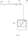
- General background on guide wire systems will be described first in conjunction with Figs. 1 and 2 .
- FIG. 1 shows a system 100 comprising a sensor guide wire 101 and a physiological monitor 130.
- the sensor guide wire 101 may comprise a sensor element 108 arranged at the distal end of the sensor guide wire 101.
- the sensor element 108 may be arranged to sense a physiological or other variable in a living body, such as a human or animal body, and provide a sensor signal.
- the sensor guide wire 101 is a disposable device which typically includes a proximal connector 112 (which may be a female or male connector) for connection to the physiological monitor 130 which processes the sensor signal to generate a measurement of the physiological or other variable.
- a signal converting device or an interfacing device may be disposed between the proximal connector 112 and the physiological monitor 130, such as for example, the signal converting and interfacing devices disclosed in U.S. Patent Application Publication No. 2012/0289808 .
- Such a signal converting or interfacing device may be arranged to interface the sensor element 108 to the physiology monitor 130 such that a signal indicative of the physiological or other variable sensed by the sensor element 108 is pre-processed and forwarded to the physiology monitor 130.
- the sensor guide wire 101 can communicate via wireless transmission with the physiological monitor 130 such as, for example, the wireless transmission arrangement disclosed in U.S. Patent Nos. 7,724,148 ; 8,174,395 ; and 8,461,997 .
- the sensor element 108 may be used to sense any suitable physiological variable, such as, for example, pressure or temperature or flow.
- the sensor may be a microchip, a pressure sensitive device in the form of a membrane, a thermistor, a sensor for measuring the concentration or presence of a blood analyte, or other suitable pressure, temperature, or other variable-measuring device.
- the sensor element 108 may be a plurality of sensor devices.
- the physiological monitor 130 may use the sensor readings from the sensor element 108 to determine blood pressure, blood temperature, blood flow, the concentration or presence of one or more blood analytes, and/or Fractional Flow Reserve measurements (FFR) or other pressure relationships.
- FFR Fractional Flow Reserve measurements
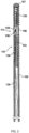
- FIG. 2 illustrates an exemplifying sensor mounted on a guide wire (as described in U.S. Patent No. 8,698,638 ) that may be used in the system of FIG. 1 .
- the sensor guide wire 101 comprises a hollow tube 102, a core wire 103, a first coil 104, a second coil 105, a jacket or sleeve 106, a dome-shaped tip 107, a sensor element or chip 108, and one or several electrical leads 109.
- the hollow tube 102 has typically been treated to give the sensor guide construction a smooth outer surface with low friction.
- the proximal end of the first coil 104 is attached to the distal end of the hollow tube 102, while the distal end of the first coil 104 is attached to the proximal end of the jacket 106.
- the proximal end of the second coil 105 is connected to the distal end of the jacket 106, and the dome-shaped tip 107 is attached to the distal end of the second coil 105.
- the core wire 103 is at least partly disposed inside the hollow tube 102 such that the distal portion of the core wire 103 extends out of the hollow tube 102 and into the second coil 105.
- the sensor element 108 is mounted on the core wire 103 at the position of the jacket 106, and is connected to an external physiology monitor (e.g., the physiological monitor 130 of FIG.
- the sensor element 108 comprises a pressure sensitive device in the form of a membrane (not shown in FIG. 2 ), which through an aperture 110 in the jacket 106 is in contact with a medium, such as blood, surrounding the distal portion of the sensor guide wire 101.
- the core wire is cylindrical and provides favorable torque transmission around a bend.
- the cylindrical core wire has no preferential bending plane, which can lead to the formation of a spiral shape in the tip resulting in poor tip durability.
- an improved sensor guide wire having a core wire including a flattened portion to provide a preferential bending plane that improves re-shapeability, and lowers the cross-sectional area moment of inertia, which in turn reduces a force required to buckle the tip and improves a tip durability by reducing the stresses experienced during bending.
- a guide wire includes a core wire having a flattened portion configured to preferentially bend the core wire in at least one plane that passes through a longitudinal axis of the core wire. A distal most end of the flattened portion is spaced from a distal most end of the core wire.
- a sensor guide wire for an intravascular measurement of a physiological variable in a living body includes a sensor element configured to measure the physiological variable, a coil, and a core wire as disclosed herein at least partially disposed within the coil.
- the portion of the core wire disposed within the coil includes a flattened portion configured to allow the core wire to preferentially bend in at least one plane that passes through a longitudinal axis of the core wire. A distal most end of the flattened portion is spaced from a distal most end of the core wire.
- FIGS. 3-8 illustrate the invention that can be used instead of the known core wire 103 of FIG. 2 .
- a sensor mounted on a guide wire including the core wire illustrated in FIGS. 3-8 may be used, for example, in the system of FIG. 1 .
- the sensor element 108 is connected to the microcables or optical signal lines 109, for transmitting signals between the sensor element 108 in the distal part of the guide wire and the connector 112 at the proximal end of the hollow tube 102.
- suitable microcables are described, for example, in U.S. Patent Application Publication No. 2010/0228112 , U.S. Patent Application Publication No. 2011/0213220 , and U.S. Patent Application Publication No. 2012/0289808 .
- the diameter of the sensor guide wire 101 preferably varies between about 0.25 to about 2.5 mm; for use in coronary arteries, for example, the diameter is normally about 0.35 mm.
- the modifier "about” can include a deviation of plus or minus 0 to 10 % of the amount it modifies, preferably plus or minus 0 to 5% of the amount it modifies.
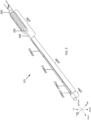
- a portion of the core wire 208 including a flattened portion 208B (which will be described below) is disposed within a coil 206 at the distal end of the sensor guide wire 101.
- the flattened portion is not provided at the distal most end of the core wire 208. Instead, a distal most end of the flattened portion 208B is spaced from a distal most end of the core wire 208 by a length of a portion 208A (described in further detail below).
- the core wire 208 may be made out of stainless steel, nitinol, or cobalt chromium.
- the core wire 208 may be made by grinding.
- the geometry of the core wire illustrated in FIGS. 3-6 is the geometry of the core wire 208 prior to being shaped by a surgeon.
- the sensor guide wire 101 and the core wire 208 can be move along three axes, namely, in a front-back direction, an up-down direction, and a right-left direction.
- the sensor guide wire 101 and the core wire 208 can also be rotated.
- the core wire 208 is disposed within the coil 206.
- the coil 206 may extend to a distal tip such as the dome-shaped tip 107 seen in FIG. 2 , but the distal portion of the coil 206 has been removed from FIG. 3 for clarity.
- the coil 206 corresponds to the second coil 105 of FIG. 2 .
- the portion of the core wire 208 disposed within the coil 206 comprises a first portion 208A at a distal end portion, a second portion 208B proximal to the first portion 208A, and a third portion 208C proximal to the second portion 208B.
- the first portion 208A (i.e., the distal most end portion) of the core wire 208 may serve as a weld paddle.
- the second portion 208B is the flattened portion of the core wire 208.
- the term "flattened portion” refers to a portion of the core wire having at least one planar surface (and sometimes two or more planar surfaces).
- the second portion 208B is not twisted.
- a length (in the front-back direction) of the first portion 208A, the second portion 208B, and the third portion 208C may be, for example, approximately 0.2 mm to 1 mm, 5 mm to 15 mm, and 15 to 25 mm, respectively.
- a length (in the front-back direction) of the first portion 208A, the second portion 208B, and the third portion 208C may be 0.5 mm, 15 mm to 16.5 mm, and 13 mm, respectively. It may be preferable to make the first portion 208A as small as possible.
- the second portion 208B i.e., the flattened portion
- the second portion 208B is the portion of the core wire 208 having the greatest length, followed by, in order of decreasing length, the third portion 208C and the first portion 208A.
- the length of each portion with respect to the remaining portions can be altered in order to change the overall mechanical properties, such as flexibility, torqueability and pushability, of the sensor guide wire 101.
- the portions 208A-208C of the core wire 208 may be connected (e.g., by welding), integrally formed or a combination thereof.
- the core wire 208 i.e., the first portion 208A, the second portion 208B and the third portion 208C
- the core wire 208 may be integrally formed from a single piece (e.g., a single piece of metal).
- the core wire 208 is formed of the same material.
- the core wire 208 may be formed from at least two pieces (e.g., multiple pieces of metal).
- each of the first portion 208A, the second portion 208B and the third portion 208C may be formed of the same metal or of different types of metal with respect to one another.
- each of the first portion 208A, the second portion 208B and the third portion 208C may be individually formed from a separate piece of metal.
- two of the first portion 208A, the second portion 208B and the third portion 208C may be formed from one piece of metal, while the remaining portion is formed from a separate piece of metal.
- the core wire 208 may optionally include a connector portion 209 configured to connect with the jacket or sleeve 106.
- the connector portion 209 may connect to a braided portion or the hollow tube 102 (if a braided portion is not provided).
- the core wire 208 may be longer than the hollow tube 102, and may extend from a proximal connector, through the jacket or sleeve 106, and to the dome-shaped tip 107 of the sensor guide wire 101.
- the portion of the core wire illustrated in FIGS. 3-6 may be the portion of the core wire present within the coil 206.
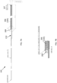
- the overall length of the core wire 208 is illustrated, for example, in FIG. 7A .
- one or more sensor elements 108 are mounted just proximal of the connector portion 209.
- the sensor element 108 may be mounted in a chip pocket 210 of FIGS. 7A and 8 .
- the first portion 208A is the portion located at the distal most end of the core wire 208.
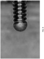
- the coil 206 is attached to the core wire 208 by thermal welding the first portion 208A to the coil 206 (see FIG. 9 ).
- the first portion 208A and the coil 206 may be melded together by laser or plasma welding. No solder is added, thereby increasing the ease of manufacturing by decreasing the amount of material required.
- a distal most end of the flattened portion 208B is spaced from a distal most end of the core wire 208, for example, by a distance equal to the length of the first portion 208A (which may be, for example, 0.5 mm, 1.0 mm, 1.5 mm or 2.0 mm). Providing such a spacing between the distal most end of the flattened portion 208B and the distal most end of the core wire 208 provides enough core wire material to be thermally welded to the coil, without impacting the strength of the flattened portion 208B or the rest of the core wire 208. As seen in FIG. 9 , the distal most end of the core wire 208 becomes spherical when thermally welded to the coil 206.
- first portion 208A, the second portion 208B and the third portion 208C have the cross-sections illustrated in FIG. 4B .
- first portion 208A and the third portion 208C are rounded (i.e., have a circular or ovular cross-section).
- the second portion 208B (i.e., the flattened portion of the core wire 208) includes a first flattened portion 208B(1) at a distal end of the flattened portion 208B, a second flattened portion 208B(2) proximal to the first flattened portion 208B(1), a third flattened portion 208B(3) proximal to the second flattened portion 208B(2), and a fourth flattened portion 208B(4) proximal to the third flattened portion 208B(3).
- first flattened portion 208B(1), the second flattened portion 208B(2), the third flattened portion 208B(3) and the fourth flattened portion 208B(4) may be integrally formed from a single piece (e.g., a single piece of metal).
- first flattened portion 208B(1), the second flattened portion 208B(2), the third flattened portion 208B(3) and the fourth flattened portion 208B(4) may be formed from at least two pieces (e.g., multiple pieces of metal).
- each of the first flattened portion 208B(1), the second flattened portion 208B(2), the third flattened portion 208B(3) and the fourth flattened portion 208B(4) may be formed of the same metal or of different types of metal with respect to one another.
- each of the first flattened portion 208B(1), the second flattened portion 208B(2), the third flattened portion 208B(3) and the fourth flattened portion 208B(4) may be individually formed from a separate piece of metal.
- first flattened portion 208B(1), the second flattened portion 208B(2), the third flattened portion 208B(3) and the fourth flattened portion 208B(4) may be formed from one piece of metal, while the remaining flattened portion(s) is formed from at least one separate piece of metal.
- a length (in the front-back direction) of the first flattened portion 208B(1), the second flattened portion 208B(2), the third flattened portion 208B(3) and the fourth flattened portion 208B(4) may be, for example, approximately 0.1 mm to 1 mm, 0.5 mm to 3 mm, 3 mm to 13 mm, and 0.5 mm to 3 mm, respectively.
- a length (in the front-back direction) of the first flattened portion 208B(1), the second flattened portion 208B(2), the third flattened portion 208B(3) and the fourth flattened portion 208B(4) may be 0.3 mm, 1.5 mm, 13 mm, and 2 mm, respectively.
- the third flattened portion 208B(3) is longer than the first flattened portion 208B(1), the second flattened portion 208B(2) and the fourth flattened portion 208B(4).
- the second flattened portion 208B(2) may have, for example, a length of 1.5 mm, a width (in the right-left direction) of 0.05 mm to 0.15 mm, and a height (in the up-down direction) of .01 mm to 0.05 mm.
- the third flattened portion 208B(3) may have, for example, a length of 13 mm, a width (in the right-left direction) of .09 mm, and a height (in the up-down direction) of .025 mm.
- the first flattened portion 208B(1) and the second flattened portion 208B(2) are round to flat transition portions disposed between the rounded first portion 208A and the third flattened portion 208B(3), which has a substantially constant rectangular or square cross-section.
- the third flattened portion 208B(3) is planar prior to being shaped by a surgeon.
- the fourth flattened portion 208B(4) is a flat to round transition portion disposed between and the third flattened portion 208B(3) and the rounded third portion 208C.
- the cross-sectional area of the core wire 208 decreases and the core wire 208 becomes progressively more flat.
- the cross-sectional area of the core wire 208 increases and the core wire 208 because progressively more round.
- each of the first portion 208A, the second portion 208B (including the flattened portions 208B(1)-208B(4)), and the third portion 208C are symmetrical with respect to at least one plane that passes through the longitudinal axis of the core wire 208.
- the sensor guide wire 101 has to be steered often several feet into a patient, for example, from an opening in the femoral artery in the leg of the patient up to the heart through tortuous blood vessels.
- the mechanical characteristics (such as maneuverability, steerability, torqueability, and pushability) of a sensor guide wire 101 are very important to a surgeon because the surgeon grasps the proximal end of the sensor guide wire 101 (sticking outside the patient), and by manipulating the proximal end, steers the distal end of the sensor guide wire 101, which is often several feet away, in the front-back direction, the up-down direction, and the right-left direction in order to reach its target (e.g., the heart).
- the distal end of the sensor guide wire 101 is going to be inserted furthest into the patient, it is desirable to make the distal end of the sensor guide wire 101 as flexible as possible so that the sensor guide wire 101 can be easily and predictably maneuvered in a tortuous path.
- the core wire 208 includes the straight and flat portion 208B(3), it is relatively easy to maneuver the core wire 208 in the front-back direction and the up-down direction by manipulating the proximal end of the sensor guide wire. However, it is more difficult to maneuver the core wire 208 in the right-left direction by manipulating the proximal end of the sensor guide wire because the core wire 208 is stiffer in the right-left direction than in the up-down direction. In other words, there is preferential movement in the up-down direction, as compared to the right-left direction. As a result, the core wire 208 exhibits preferential bending in a plane extending along the up-down direction.
- the core wire 208 exhibits preferential bending in the up direction to the same degree as the core wire 208 exhibits preferential bending in the down direction. This preferential bending allows a physician to bend the sensor guide wire 101, in particular, the core wire 208 in a predictable direction.
- torque supplied to the proximal end of the core wire 208 is transmitted along the length of the core wire 208 and enables the core wire 208, in particular, the flattened portion 208B (which may be shaped) to be easily reoriented to point in the desired direction.
- the core wire 208 resists bending in the right-left direction, thereby allowing the surgeon to more easily route the core wire 208 to the target.
- the flattened portion 208B improves re-shapeability by providing a consistent and preferential bending plane.
- the flattened portion 208B allows the sensor guide wire 101 to retain less permanent deformation when subjected to bending conditions.
- the flattened portion 208B also lowers the cross-sectional area moment of inertia, which in turn reduces the force to buckle the dome-shaped tip 107 and improves the durability of the dome-shaped tip 107 by reducing the stresses experienced during bending.
- the core wire 208 includes both a round proximal portion (i.e., the third portion 208C) and a flattened portion (i.e., the second portion 208B) that is distal to the third portion 208C.
- the round proximal portion provides a certain level of stiffness for steerability in tortuous anatomies and the flattened portion provides a shaping region where the physician can manipulate the core wire to preferentially bend in an up-down direction in curves or bends to meet the needs of the use scenario.
- FIG. 8 illustrates an example of the sensor guide wire 101 comprising a core wire as described above, including illustrative dimensions having units of millimeters.
- the core wire 208 may have different configurations within the scope of the appended claims, provided that the core wire 208 includes at least one flattened portion (or other shape that has a preferential bending direction, such as an elongated ellipse). Further examples are not according to the invention and are present only for illustrative purposes.
- the entire core wire 208 may be flat.
- the core wire 208 may include a flattened portion and at least one rounded portion.
- the term "rounded portion” refers to a portion of the core wire having a circular or ovular cross-section. In other words, the rounded portion of the core wire does not include any flattened portions.
- the core wire 208 may include a first rounded portion (e.g., the first portion 208A), a second rounded portion (e.g., the third portion 208C), and a flattened portion (e.g., the second portion 208B) provided between the first rounded portion and the second rounded portion.
- the core wire 208 may include a plurality of flattened portions and at least one rounded portion. A first flattened portion may have the same dimensions as a second flattened portion, or the first flattened portion may have different dimensions from the second flattened portion.
- the first flattened portion and the second flattened portion may be immediately adjacent to each other or the first flattened portion and the second flattened portion may be separated by at least one rounded portion.
- the core wire 208 may include more than two flattened portions.
- the core wire 208 may have more than three portions, or the core wire 208 may have fewer than three portions.
- the first portion 208A and/or the third portion 208C may be omitted.
- the proximal end of the second portion 208B may directly connect to the connector portion 209 or extend to and mate with the jacket or sleeve 106. Any portion except for the second portion 208B (i.e., the flattened portion) may be omitted.
- additional flattened and rounded portions may be added.
- the entire core wire 208 may be flat (i.e., the core wire 208 may consist of only the flattened portion 208B).
- the core wire described in any of the embodiments may also be used with a guide wire without a sensor or a guide wire with or without a braided portion.
- the core wire described in any of the embodiments may also be used with a guide wire without a coil.
Landscapes
- Health & Medical Sciences (AREA)
- Life Sciences & Earth Sciences (AREA)
- Animal Behavior & Ethology (AREA)
- Biophysics (AREA)
- Veterinary Medicine (AREA)
- Engineering & Computer Science (AREA)
- Biomedical Technology (AREA)
- Heart & Thoracic Surgery (AREA)
- Public Health (AREA)
- General Health & Medical Sciences (AREA)
- Surgery (AREA)
- Physics & Mathematics (AREA)
- Molecular Biology (AREA)
- Medical Informatics (AREA)
- Pathology (AREA)
- Pulmonology (AREA)
- Anesthesiology (AREA)
- Hematology (AREA)
- Media Introduction/Drainage Providing Device (AREA)
- Measuring Pulse, Heart Rate, Blood Pressure Or Blood Flow (AREA)
Claims (21)
- Führungsdraht (101), der für die intravaskuläre Einführung konfiguriert ist, wobei der Führungsdraht (101) Folgendes umfasst:einen Kerndraht (208), umfassend, in einer Richtung von einem distalen Ende des Kerndrahtes (208) zu einem proximalen Ende des Kerndrahtes (208):einen ersten abgerundeten Abschnitt (208A), der an einem distalsten Ende des Kerndrahtes (208) angeordnet ist,einen zweiten Abschnitt (208B), der konfiguriert ist, um dem Kerndraht (208) zu ermöglichen, sich vorzugsweise in mindestens einer durch eine Längsachse des Kerndrahtes (208) verlaufenden Ebene zu biegen; undeinen dritten abgerundeten Abschnitt (208C); wobei:wobei der zweite Abschnitt (208B) einen ersten abgeflachten Abschnitt (208B(1)), einen zweiten abgeflachten Abschnitt (208B(2)), einen dritten abgeflachten Abschnitt (208B(3)) und einen vierten abgeflachten Abschnitt (208B(4)) umfasst, wobei:von dem ersten Abschnitt (208A) zu dem dritten abgeflachten Abschnitt (208B(3)) die Querschnittsfläche des Kerndrahtes (208) abnimmt und der Kerndraht (208) zunehmend flacher wird, und von dem dritten abgeflachten Abschnitt (208B(3)) zu dem dritten abgerundeten Abschnitt (208C) die Querschnittsfläche des Kerndrahtes (208) zunimmt und der Kerndraht (208) zunehmend runder wird.- der erste abgeflachte Abschnitt (208B(1)) und der zweite abgeflachte Abschnitt (208B(2)) runde bis flache Übergangsabschnitte sind, die zwischen dem abgerundeten ersten Abschnitt (208A) und dem dritten abgeflachten Abschnitt (208B(3)) befindlich sind,- der dritte abgeflachte Abschnitt (208B(3)) einen im Wesentlichen konstanten rechteckigen oder quadratischen Querschnitt aufweist,- der vierte abgeflachte Abschnitt (208B(4)) ein flacher bis runder Übergangsabschnitt ist, der zwischen dem dritten abgeflachten Abschnitt (208B(3)) und dem abgerundeten dritten Abschnitt (208C) befindlich ist, und wobei
- Führungsdraht (101) nach Anspruch 1, wobei eine Querschnittsfläche des zweiten abgerundeten Abschnitts (208C) größer ist als eine Querschnittsfläche an einem proximalen Ende des dritten abgeflachten Abschnitts (208B(3)).
- Führungsdraht (101) nach Anspruch 1, wobei eine Gesamtlänge des zweiten und dritten abgeflachten Abschnitts (208B(2) und 208B(3)) größer ist als eine Länge des ersten abgerundeten Abschnitts (208A) und größer als eine Länge des zweiten abgerundeten Abschnitts (208C).
- Führungsdraht (101) nach Anspruch 1, wobei ein Querschnitt jedes des ersten abgerundeten Abschnitts (208A), des zweiten abgeflachten Abschnitts (208B(2)), des dritten abgeflachten Abschnitts (208B(3)) und des zweiten abgerundeten Abschnitts (208C) symmetrisch in Bezug auf mindestens eine Ebene ist, die durch die Längsachse des Kerndrahtes (208) verläuft und sich entlang dieser erstreckt.
- Führungsdraht (101) nach Anspruch 1, wobei der erste abgerundete Abschnitt (208A), der zweite abgeflachte Abschnitt (208B(2)), der dritte abgeflachte Abschnitt (208B(3)) und der zweite abgerundete Abschnitt (208C) ganzheitlich aus einem einzigen Stück gebildet sind.
- Führungsdraht (101) nach Anspruch 1, wobei eine Gesamtlänge des zweiten und dritten abgeflachten Abschnitts (208B(2) und 208B(3)) größer ist als eine Länge des ersten abgeflachten Abschnitts (208B(1)) und größer als eine Länge des vierten abgeflachten Abschnitts (208B(4)).
- Führungsdraht (101) nach Anspruch 1, ferner umfassend:ein Sensorelement (108), das zum Messen einer physiologischen Variable in einem lebenden Körper konfiguriert ist; undeine Spule (206),wobei ein Abschnitt des Kerndrahtes (208) innerhalb der Spule (206) befindlich ist.
- Führungsdraht (101) nach Anspruch 7, wobei mindestens ein Abschnitt des dritten abgeflachten Abschnitts (208B(3)) innerhalb der Spule befindlich ist.
- Führungsdraht (101) nach Anspruch 7, ferner umfassend einen Mantel (106) proximal zu der Spule, wobei die Spule (206) an einem Innenumfang oder einem Außenumfang des Mantels (106) befestigt ist.
- Führungsdraht (101) nach Anspruch 9, wobei der innerhalb der Spule (206) befindliche Abschnitt des Kerndrahtes (208) ferner einen Verbindungsabschnitt umfasst, der konfiguriert ist, um sich mit einem distalen Ende des Mantels (106) zu verbinden.
- Führungsdraht (101) nach Anspruch 1, wobei der erste abgerundete Abschnitt (208A) einen kreisförmigen Querschnitt aufweist.
- Führungsdraht (101) nach Anspruch 1, wobei der zweite abgerundete Abschnitt (208C) einen kreisförmigen Querschnitt aufweist.
- Führungsdraht nach Anspruch 1, wobei:der erste abgeflachte Abschnitt (208B(1)) direkt neben dem ersten abgerundeten Abschnitt (208A) angeordnet ist und sich proximal von dem ersten abgerundeten Abschnitt (208A) erstreckt,der zweite abgeflachte Abschnitt (208B(2)) direkt neben dem ersten abgeflachten Abschnitt (208B(1)) angeordnet ist undsich proximal von dem ersten abgeflachten Abschnitt (208B(1)) erstreckt,der dritte abgeflachte Abschnitt (208B(3)) direkt neben dem zweiten abgeflachten Abschnitt (208B(2)) angeordnet ist und sich proximal von dem zweiten abgeflachten Abschnitt (208B(2)) erstreckt.
- Führungsdraht nach Anspruch 1, wobei in einer Querschnittsansicht des ersten abgeflachten Abschnitts (208B(1)) der erste abgeflachte Abschnitt (208B(1)) zwei einander gegenüberliegende abgerundete Seiten und zwei einander gegenüberliegende flache Seiten aufweist.
- Führungsdraht nach Anspruch 1, wobei in einer Querschnittsansicht des vierten abgeflachten Abschnitts (208B(4)) der vierte abgeflachte Abschnitt (208B(4)) zwei einander gegenüberliegende abgerundete Seiten und zwei einander gegenüberliegende flache Seiten aufweist.
- Führungsdraht nach Anspruch 1, wobei:in einer Querschnittsansicht des zweiten abgeflachten Abschnitts (208B(2)) der zweite abgeflachte Abschnitt (208B(2)) zwei einander gegenüberliegende abgerundete Seiten und zwei einander gegenüberliegende flache Seiten aufweist, undin einer Querschnittsansicht des dritten abgeflachten Abschnitts (208B(3)) der dritte abgeflachte Abschnitt (208B(3)) zwei einander gegenüberliegende abgerundete Seiten und zwei einander gegenüberliegende flache Seiten aufweist.
- Führungsdraht nach Anspruch 1, wobei:der dritte abgeflachte Abschnitt (208B(3)) direkt neben dem zweiten abgeflachten Abschnitt (208B(2)) angeordnet ist und sich proximal von dem zweiten abgeflachten Abschnitt (208B(2)) erstreckt, undder Kerndraht (208) in einer proximalen Richtung entlang eines Abschnitts, der sich zumindest von dem distalen Ende des zweiten abgeflachten Abschnitts (208B(2)) zu dem distalen Ende des dritten abgeflachten Abschnitts (208B(3)) erstreckt, zunehmend flacher wird.
- Führungsdraht nach Anspruch 1, wobei:eine Länge des ersten abgerundeten Abschnitts (208A) in einem Bereich von 0,2 mm bis 1 mm liegt,eine Länge des ersten abgeflachten Abschnitts (208B(1)) in einem Bereich von 0,1 mm bis 1 mm liegt,eine Länge des zweiten abgeflachten Abschnitts (208B(2)) in einem Bereich von 0,5 mm bis 3 mm liegt,eine Länge des dritten abgeflachten Abschnitts (208B(3)) in einem Bereich von 3 mm bis 13 mm liegt,eine Länge des vierten abgeflachten Abschnitts (208B(4)) in einem Bereich von 0,5 mm bis 3 mm liegt, undeine Länge des dritten abgerundeten Abschnitts (208C) in einem Bereich von 15 mm bis 25 mm liegt.
- Führungsdraht nach Anspruch 1, wobei eine Höhe des zweiten abgeflachten Abschnitts (208B(2)) in einer Richtung zwischen flachen Oberflächen des zweiten abgeflachten Abschnitts (208B (2)) in einem Bereich von 0,01 mm bis 0,05 mm liegt.
- Führungsdraht nach Anspruch 19, wobei eine Höhe des dritten abgeflachten Abschnitts (208B(3)) in einer Richtung zwischen flachen Oberflächen des dritten abgeflachten Abschnitts (208B(3)) 0,025 mm beträgt.
- Führungsdraht nach Anspruch 1, wobei:
eine Breite des zweiten abgeflachten Abschnitts (208B(2)) in einer Richtung senkrecht zu einer Richtung zwischen flachen Oberflächen des zweiten abgeflachten Abschnitts (208B(2)) größer ist als eine Breite des dritten abgeflachten Abschnitts (208B(3)) in einer Richtung senkrecht zu einer Richtung zwischen flachen Oberflächen des dritten abgeflachten Abschnitts (208B(3)).
Applications Claiming Priority (2)
| Application Number | Priority Date | Filing Date | Title |
|---|---|---|---|
| US15/072,021 US10792473B2 (en) | 2016-03-16 | 2016-03-16 | Core wire having a flattened portion to provide preferential bending |
| PCT/US2017/022514 WO2017160987A1 (en) | 2016-03-16 | 2017-03-15 | Core wire having a flattened portion to provide preferential bending |
Publications (2)
| Publication Number | Publication Date |
|---|---|
| EP3429459A1 EP3429459A1 (de) | 2019-01-23 |
| EP3429459B1 true EP3429459B1 (de) | 2024-07-24 |
Family
ID=58461456
Family Applications (1)
| Application Number | Title | Priority Date | Filing Date |
|---|---|---|---|
| EP17714961.4A Active EP3429459B1 (de) | 2016-03-16 | 2017-03-15 | Kerndraht mit einem abgeflachten abschnitt zur ermöglichung einer bevorzugten biegung |
Country Status (5)
| Country | Link |
|---|---|
| US (1) | US10792473B2 (de) |
| EP (1) | EP3429459B1 (de) |
| JP (1) | JP2019511270A (de) |
| ES (1) | ES2988344T3 (de) |
| WO (1) | WO2017160987A1 (de) |
Families Citing this family (4)
| Publication number | Priority date | Publication date | Assignee | Title |
|---|---|---|---|---|
| US11154692B2 (en) | 2019-10-30 | 2021-10-26 | Rapid Medical Ltd. | Intraluminal device with looped core wire |
| US12420067B2 (en) * | 2020-05-12 | 2025-09-23 | Boston Scientific Medical Device Limited | Guidewire assembly |
| WO2021250133A1 (en) * | 2020-06-10 | 2021-12-16 | Hexacath | Catheter systems for having both a thermodilution action and a body obstruction destruction action, and methods for determining blood flow rates and for performing body obstruction destruction |
| US20240009430A1 (en) * | 2022-07-08 | 2024-01-11 | Abbott Cardiovascular Systems Inc. | Guidewire core having non-round cross-sections |
Citations (3)
| Publication number | Priority date | Publication date | Assignee | Title |
|---|---|---|---|---|
| US20020019626A1 (en) * | 2000-02-25 | 2002-02-14 | Sharkey Hugh R. | Apparatus and method for accessing and performing a function within an intervertebral disc |
| US20090227902A1 (en) * | 2004-08-31 | 2009-09-10 | Abbott Cardiovascular Systems, Inc. | Guide wire with core having welded wire segments |
| US20130172782A1 (en) * | 2010-09-29 | 2013-07-04 | St. Jude Medical Systems Ab | Sensor guide wire |
Family Cites Families (93)
| Publication number | Priority date | Publication date | Assignee | Title |
|---|---|---|---|---|
| US4854330A (en) * | 1986-07-10 | 1989-08-08 | Medrad, Inc. | Formed core catheter guide wire assembly |
| US4811743A (en) * | 1987-04-21 | 1989-03-14 | Cordis Corporation | Catheter guidewire |
| USRE37148E1 (en) | 1990-06-04 | 2001-04-24 | Medtronic Ave, Inc. | Guidewire tip construction |
| SE506135C2 (sv) | 1990-07-11 | 1997-11-17 | Radi Medical Systems | Sensor- och ledarkonstruktion |
| CA2068584C (en) | 1991-06-18 | 1997-04-22 | Paul H. Burmeister | Intravascular guide wire and method for manufacture thereof |
| US6464700B1 (en) | 1994-10-07 | 2002-10-15 | Scimed Life Systems, Inc. | Loop structures for positioning a diagnostic or therapeutic element on the epicardium or other organ surface |
| US7175619B2 (en) | 1994-10-07 | 2007-02-13 | Boston Scientific Scimed, Inc. | Loop structures for positioning a diagnostic or therapeutic element on the epicardium or other organ surface |
| US5520635A (en) | 1994-12-16 | 1996-05-28 | Gelbfish; Gary A. | Method and associated device for removing clot |
| US5707354A (en) | 1995-04-17 | 1998-01-13 | Cardiovascular Imaging Systems, Inc. | Compliant catheter lumen and methods |
| SE9600333D0 (sv) | 1995-06-22 | 1996-01-30 | Radi Medical Systems | Sensor arrangement |
| US5836893A (en) | 1996-03-08 | 1998-11-17 | Scimed Life Systems, Inc. | Intravascular guidewire |
| US6251086B1 (en) | 1999-07-27 | 2001-06-26 | Scimed Life Systems, Inc. | Guide wire with hydrophilically coated tip |
| US6190332B1 (en) | 1998-02-19 | 2001-02-20 | Percusurge, Inc. | Core wire with shapeable tip |
| US7455646B2 (en) | 1997-06-04 | 2008-11-25 | Advanced Cardiovascular Systems, Inc. | Polymer coated guide wire |
| US5957865A (en) | 1997-09-25 | 1999-09-28 | Merit Medical Systems, Inc. | Flexible catheter guidewire |
| US6078831A (en) | 1997-09-29 | 2000-06-20 | Scimed Life Systems, Inc. | Intravascular imaging guidewire |
| US5951480A (en) | 1997-09-29 | 1999-09-14 | Boston Scientific Corporation | Ultrasound imaging guidewire with static central core and tip |
| DE69832408T2 (de) | 1997-09-29 | 2006-09-28 | Boston Scientific Ltd., St. Michael | Führungskatheter zur intravaskulären bilderzeugung |
| US5980471A (en) * | 1997-10-10 | 1999-11-09 | Advanced Cardiovascular System, Inc. | Guidewire with tubular connector |
| US6464699B1 (en) | 1997-10-10 | 2002-10-15 | Scimed Life Systems, Inc. | Method and apparatus for positioning a diagnostic or therapeutic element on body tissue and mask element for use with same |
| JP3876080B2 (ja) | 1998-10-02 | 2007-01-31 | テルモ株式会社 | 医療用ワイヤ |
| US6142958A (en) | 1998-12-23 | 2000-11-07 | Radi Medical Systems Ab | Sensor and guide wire assembly |
| EP1479407B1 (de) | 1998-12-23 | 2006-03-01 | Radi Medical Systems Ab | Sensor und Führungsdrahteinheit |
| US6352515B1 (en) * | 1999-12-13 | 2002-03-05 | Advanced Cardiovascular Systems, Inc. | NiTi alloyed guidewires |
| US6290656B1 (en) * | 1999-12-30 | 2001-09-18 | Advanced Cardiovascular Systems, Inc. | Guide wire with damped force vibration mechanism |
| US6692491B1 (en) | 2000-03-24 | 2004-02-17 | Scimed Life Systems, Inc. | Surgical methods and apparatus for positioning a diagnostic or therapeutic element around one or more pulmonary veins or other body structures |
| EP1267737B1 (de) | 2000-03-24 | 2005-10-19 | Boston Scientific Limited | Schlaufe zum positionieren einer diagnostischen oder therapeutischen vorrichtung auf das epikard oder einer anderen organoberfläche |
| SE0002515D0 (sv) | 2000-06-30 | 2000-06-30 | Pacesetter Ab | Locator device |
| US8257278B2 (en) | 2002-05-14 | 2012-09-04 | Advanced Cardiovascular Systems, Inc. | Metal composite guide wire |
| US6866642B2 (en) | 2002-11-25 | 2005-03-15 | Advanced Cardiovascular Systems, Inc. | Enhanced method for joining two core wires |
| US20040167438A1 (en) | 2003-02-26 | 2004-08-26 | Sharrow James S. | Reinforced medical device |
| US7169118B2 (en) | 2003-02-26 | 2007-01-30 | Scimed Life Systems, Inc. | Elongate medical device with distal cap |
| US7182735B2 (en) | 2003-02-26 | 2007-02-27 | Scimed Life Systems, Inc. | Elongated intracorporal medical device |
| US20040193034A1 (en) | 2003-03-28 | 2004-09-30 | Lawrence Wasicek | Combined long rail/short rail IVUS catheter |
| ATE300233T1 (de) | 2003-05-09 | 2005-08-15 | Radi Medical Systems | Führungsdrahteinheit mir sensor |
| US7789839B2 (en) | 2003-08-07 | 2010-09-07 | Brivant Research & Development Limited | Guide wire for use with a catheter |
| US8602974B2 (en) | 2003-08-13 | 2013-12-10 | G.I. View Ltd. | Gastrointestinal tool over guiding element |
| JP3726266B2 (ja) | 2003-10-02 | 2005-12-14 | 朝日インテック株式会社 | 医療用ガイドワイヤの先端部構造 |
| JP2006026406A (ja) | 2004-07-12 | 2006-02-02 | Radi Medical Systems Ab | 生理学的変数の無線による通信 |
| EP1616521B1 (de) | 2004-07-12 | 2007-11-21 | Radi Medical Systems Ab | Drahtlose Kommunikation physiologischer Variablen |
| US8277386B2 (en) | 2004-09-27 | 2012-10-02 | Volcano Corporation | Combination sensor guidewire and methods of use |
| JP4907945B2 (ja) | 2004-11-01 | 2012-04-04 | テルモ株式会社 | 医療用ガイドワイヤ |
| DE102004058008B4 (de) | 2004-12-01 | 2007-08-23 | Siemens Ag | Führungsdraht für Gefäßkatheter mit verbesserter Ortungs- und Navigiermöglichkeit |
| US20060247672A1 (en) | 2005-04-27 | 2006-11-02 | Vidlund Robert M | Devices and methods for pericardial access |
| US8075497B2 (en) | 2005-08-25 | 2011-12-13 | Cook Medical Technologies Llc | Wire guide having distal coupling tip |
| US8608703B2 (en) | 2007-06-12 | 2013-12-17 | Medrad, Inc. | Infusion flow guidewire system |
| US20070167972A1 (en) * | 2006-01-17 | 2007-07-19 | Euteneuer Charles L | Balloon apparatus and methods |
| CN101384293B (zh) | 2006-03-06 | 2013-04-24 | 泰尔茂株式会社 | 导丝 |
| US20070244413A1 (en) | 2006-04-12 | 2007-10-18 | Medtronic Vascular, Inc. | Medical guidewire tip construction |
| US20070255145A1 (en) | 2006-04-28 | 2007-11-01 | Radi Medical Systems Ab | Sensor and guide wire assembly |
| US8133190B2 (en) | 2006-06-22 | 2012-03-13 | Cook Medical Technologies Llc | Weldable wire guide with distal coupling tip |
| US8419658B2 (en) | 2006-09-06 | 2013-04-16 | Boston Scientific Scimed, Inc. | Medical device including structure for crossing an occlusion in a vessel |
| US20080119762A1 (en) | 2006-11-16 | 2008-05-22 | Tateishi Tadasu | Guide wire |
| US7724148B2 (en) | 2006-11-20 | 2010-05-25 | Radi Medical Systems Ab | Transceiver unit in a pressure measurement system |
| US8174395B2 (en) | 2006-11-20 | 2012-05-08 | St. Jude Medical Systems Ab | Transceiver unit in a measurement system |
| US8461997B2 (en) | 2006-11-20 | 2013-06-11 | St. Jude Medical Systems Ab | Transceiver unit in a measurement system |
| US9028427B2 (en) | 2007-03-14 | 2015-05-12 | Terumo Kabushiki Kaisha | Guide wire |
| US20090062602A1 (en) | 2007-07-30 | 2009-03-05 | Hansen Medical, Inc. | Apparatus for robotic instrument having variable flexibility and torque transmission |
| US8105246B2 (en) | 2007-08-03 | 2012-01-31 | Boston Scientific Scimed, Inc. | Elongate medical device having enhanced torque and methods thereof |
| US8360995B2 (en) | 2007-09-18 | 2013-01-29 | Cook Medical Technologies Llc | Wire guide |
| US9289137B2 (en) | 2007-09-28 | 2016-03-22 | Volcano Corporation | Intravascular pressure devices incorporating sensors manufactured using deep reactive ion etching |
| US20100318000A1 (en) | 2007-10-26 | 2010-12-16 | St.Jude Medical Systems Ab | Sensor guide wire |
| EP2211701A1 (de) | 2007-10-26 | 2010-08-04 | St. Jude Medical Systems AB | Sensor-führungsdraht mit mikrokabelwicklung |
| US8460213B2 (en) | 2008-01-03 | 2013-06-11 | Boston Scientific Scimed, Inc. | Cut tubular members for a medical device and methods for making and using the same |
| CA2650705C (en) | 2008-01-23 | 2017-07-11 | Mediguide Ltd. | Guidewire interconnecting apparatus |
| US9095685B2 (en) * | 2008-01-23 | 2015-08-04 | Mediguide Ltd. | Sensor mounted flexible guidewire |
| US7713215B2 (en) | 2008-01-31 | 2010-05-11 | Shriver Edgar L | Steering, piercing, anchoring, distending extravascular guidewire |
| US8376961B2 (en) | 2008-04-07 | 2013-02-19 | Boston Scientific Scimed, Inc. | Micromachined composite guidewire structure with anisotropic bending properties |
| ES2700863T3 (es) | 2008-07-30 | 2019-02-19 | Acclarent Inc | Dispositivos de localización del ostium paranasal |
| JP2010187929A (ja) | 2009-02-18 | 2010-09-02 | Morioka Seiko Instruments Inc | カテーテル及びカテーテルの製造方法 |
| US8241248B2 (en) | 2009-02-27 | 2012-08-14 | Cvdevices, Llc | Devices and systems for selective auto-retroperfusion of the cerebral venous system |
| JP4913198B2 (ja) | 2009-10-27 | 2012-04-11 | 株式会社パテントストラ | 医療用ガイドワイヤ、医療用ガイドワイヤの製造方法、医療用ガイドワイヤとマイクロカテーテルとガイディングカテーテルとの組立体、および医療用ガイドワイヤとバルーンカテーテルとガイディングカテーテルとの組立体 |
| JP5004256B2 (ja) | 2009-12-25 | 2012-08-22 | 朝日インテック株式会社 | 医療用ガイドワイヤ |
| SE534291C2 (sv) | 2010-01-27 | 2011-06-28 | St Jude Medical Systems Ab | Sensorstyrtrådsanordning och system för intravaskulära mätningar av en fysiologisk variabel |
| US8696600B2 (en) | 2010-01-29 | 2014-04-15 | St. Jude Medical Systems Ab | Medical guide wire assembly |
| EP2552530A1 (de) | 2010-03-31 | 2013-02-06 | Boston Scientific Scimed, Inc. | Führungsdraht mit einem biegefestigkeitsprofil |
| JP5229830B2 (ja) | 2010-06-25 | 2013-07-03 | 朝日インテック株式会社 | 医療用ガイドワイヤ |
| EP2402051B1 (de) | 2010-06-30 | 2019-10-02 | Asahi Intecc Co., Ltd. | Medizinischer Führungsdraht |
| US20120041342A1 (en) | 2010-08-16 | 2012-02-16 | Abbott Cardiovascular Systems Inc. | High durability coronary guide wire |
| US9155492B2 (en) | 2010-09-24 | 2015-10-13 | Acclarent, Inc. | Sinus illumination lightwire device |
| JP5382953B2 (ja) | 2011-01-28 | 2014-01-08 | 朝日インテック株式会社 | ガイドワイヤ |
| JP5751624B2 (ja) | 2011-06-21 | 2015-07-22 | 朝日インテック株式会社 | ガイドワイヤ |
| WO2013082032A1 (en) | 2011-11-28 | 2013-06-06 | Mazar Scott T | Steerable guide wire with pressure sensor |
| EP2866872A4 (de) | 2012-06-28 | 2016-07-06 | Volcano Corp | Intravaskuläre vorrichtungen, systeme und verfahren |
| US9895108B2 (en) | 2012-08-31 | 2018-02-20 | Volcano Corporation | Pressure sensing intravascular devices with reduced drift and associated systems and methods |
| EP2890291B1 (de) | 2012-08-31 | 2020-06-24 | Volcano Corporation | Montagestrukturen für komponenten intravaskulärer vorrichtungen |
| US20140180166A1 (en) * | 2012-12-20 | 2014-06-26 | Cook Medical Technologies Llc | Guide wire |
| US20140180141A1 (en) | 2012-12-21 | 2014-06-26 | Volcano Corporation | Mounting Structures for Components of Intravascular Devices |
| US9924903B2 (en) | 2012-12-27 | 2018-03-27 | Volcano Corporation | Pressure-sensing guide wire with sliding pressure sensor |
| US20140187978A1 (en) | 2012-12-28 | 2014-07-03 | Volcano Corporation | Intravascular Devices Having Information Stored Thereon And/Or Wireless Communication Functionality, Including Associated Devices, Systems, And Methods |
| JP2014023943A (ja) | 2013-09-12 | 2014-02-06 | Asahi Intecc Co Ltd | ガイドワイヤ |
| US20150094616A1 (en) * | 2013-09-30 | 2015-04-02 | Abbott Cardiovascular Systems, Inc. | Guide wire core with improved torsional ductility |
| EP3171764B1 (de) * | 2014-07-22 | 2023-06-07 | Koninklijke Philips N.V. | Intravaskuläre vorrichtungen, systeme und verfahren mit einem kerndraht mit mehreren abgeflachten abschnitten |
-
2016
- 2016-03-16 US US15/072,021 patent/US10792473B2/en active Active
-
2017
- 2017-03-15 JP JP2018544541A patent/JP2019511270A/ja active Pending
- 2017-03-15 ES ES17714961T patent/ES2988344T3/es active Active
- 2017-03-15 EP EP17714961.4A patent/EP3429459B1/de active Active
- 2017-03-15 WO PCT/US2017/022514 patent/WO2017160987A1/en not_active Ceased
Patent Citations (3)
| Publication number | Priority date | Publication date | Assignee | Title |
|---|---|---|---|---|
| US20020019626A1 (en) * | 2000-02-25 | 2002-02-14 | Sharkey Hugh R. | Apparatus and method for accessing and performing a function within an intervertebral disc |
| US20090227902A1 (en) * | 2004-08-31 | 2009-09-10 | Abbott Cardiovascular Systems, Inc. | Guide wire with core having welded wire segments |
| US20130172782A1 (en) * | 2010-09-29 | 2013-07-04 | St. Jude Medical Systems Ab | Sensor guide wire |
Also Published As
| Publication number | Publication date |
|---|---|
| US20170266417A1 (en) | 2017-09-21 |
| US10792473B2 (en) | 2020-10-06 |
| ES2988344T3 (es) | 2024-11-20 |
| JP2019511270A (ja) | 2019-04-25 |
| EP3429459A1 (de) | 2019-01-23 |
| WO2017160987A1 (en) | 2017-09-21 |
Similar Documents
| Publication | Publication Date | Title |
|---|---|---|
| US12109009B2 (en) | Intravascular devices, systems, and methods having a core wire with embedded conductors | |
| EP2338556B1 (de) | Führungsdraht | |
| JP6619790B2 (ja) | 低侵襲性チップを備えるカテーテル | |
| US10226185B2 (en) | Tube and sensor guide wire comprising tube | |
| EP3095482B1 (de) | Katheter mit verstellbarer deflektion | |
| EP3122240B1 (de) | Intravaskuläre vorrichtungen, systeme und verfahren mit einem kerndraht aus mehreren materialien | |
| EP3171764B1 (de) | Intravaskuläre vorrichtungen, systeme und verfahren mit einem kerndraht mit mehreren abgeflachten abschnitten | |
| US11006840B2 (en) | Device, system, and method for assessing intravascular pressure | |
| US10470713B2 (en) | Sensor guide wire device and system including a sensor guide wire device | |
| EP2209419B1 (de) | Fàhrungsdrahteinheit mir sensor | |
| JP2008520347A (ja) | トルク応答性及び曲線保持性が改善されたカテーテル | |
| EP3324837B1 (de) | Intravaskuläre vorrichtungen, systeme und verfahren mit einem angeklebten formband | |
| US10792473B2 (en) | Core wire having a flattened portion to provide preferential bending | |
| WO2009054800A1 (en) | Sensor guide wire | |
| US10350389B2 (en) | Intravascular devices, systems, and methods having a radiopaque patterned flexible tip | |
| US20160287178A1 (en) | Sensor guide wire having a proximal tube with improved torque performance and maintained low bending stiffness | |
| WO2016038488A1 (en) | Intravascular devices, systems, and methods having a sensing element embedded in adhesive | |
| US20180184981A1 (en) | Intravascular devices systems and methods with a solid core proximal section and a slotted tubular distal section | |
| CN220109771U (zh) | 感测三维力的光纤和导丝 | |
| EP4728962A1 (de) | Längliche vorrichtung zur medizinischen interventionellen anwendung |
Legal Events
| Date | Code | Title | Description |
|---|---|---|---|
| STAA | Information on the status of an ep patent application or granted ep patent |
Free format text: STATUS: UNKNOWN |
|
| STAA | Information on the status of an ep patent application or granted ep patent |
Free format text: STATUS: THE INTERNATIONAL PUBLICATION HAS BEEN MADE |
|
| PUAI | Public reference made under article 153(3) epc to a published international application that has entered the european phase |
Free format text: ORIGINAL CODE: 0009012 |
|
| STAA | Information on the status of an ep patent application or granted ep patent |
Free format text: STATUS: REQUEST FOR EXAMINATION WAS MADE |
|
| 17P | Request for examination filed |
Effective date: 20180911 |
|
| AK | Designated contracting states |
Kind code of ref document: A1 Designated state(s): AL AT BE BG CH CY CZ DE DK EE ES FI FR GB GR HR HU IE IS IT LI LT LU LV MC MK MT NL NO PL PT RO RS SE SI SK SM TR |
|
| AX | Request for extension of the european patent |
Extension state: BA ME |
|
| DAV | Request for validation of the european patent (deleted) | ||
| DAX | Request for extension of the european patent (deleted) | ||
| STAA | Information on the status of an ep patent application or granted ep patent |
Free format text: STATUS: EXAMINATION IS IN PROGRESS |
|
| 17Q | First examination report despatched |
Effective date: 20190625 |
|
| P01 | Opt-out of the competence of the unified patent court (upc) registered |
Effective date: 20230623 |
|
| GRAP | Despatch of communication of intention to grant a patent |
Free format text: ORIGINAL CODE: EPIDOSNIGR1 |
|
| STAA | Information on the status of an ep patent application or granted ep patent |
Free format text: STATUS: GRANT OF PATENT IS INTENDED |
|
| INTG | Intention to grant announced |
Effective date: 20240220 |
|
| GRAS | Grant fee paid |
Free format text: ORIGINAL CODE: EPIDOSNIGR3 |
|
| GRAA | (expected) grant |
Free format text: ORIGINAL CODE: 0009210 |
|
| STAA | Information on the status of an ep patent application or granted ep patent |
Free format text: STATUS: THE PATENT HAS BEEN GRANTED |
|
| AK | Designated contracting states |
Kind code of ref document: B1 Designated state(s): AL AT BE BG CH CY CZ DE DK EE ES FI FR GB GR HR HU IE IS IT LI LT LU LV MC MK MT NL NO PL PT RO RS SE SI SK SM TR |
|
| REG | Reference to a national code |
Ref country code: GB Ref legal event code: FG4D |
|
| REG | Reference to a national code |
Ref country code: CH Ref legal event code: EP |
|
| REG | Reference to a national code |
Ref country code: DE Ref legal event code: R096 Ref document number: 602017083501 Country of ref document: DE |
|
| REG | Reference to a national code |
Ref country code: IE Ref legal event code: FG4D |
|
| REG | Reference to a national code |
Ref country code: LT Ref legal event code: MG9D |
|
| REG | Reference to a national code |
Ref country code: ES Ref legal event code: FG2A Ref document number: 2988344 Country of ref document: ES Kind code of ref document: T3 Effective date: 20241120 |
|
| REG | Reference to a national code |
Ref country code: NL Ref legal event code: MP Effective date: 20240724 |
|
| PG25 | Lapsed in a contracting state [announced via postgrant information from national office to epo] |
Ref country code: PT Free format text: LAPSE BECAUSE OF FAILURE TO SUBMIT A TRANSLATION OF THE DESCRIPTION OR TO PAY THE FEE WITHIN THE PRESCRIBED TIME-LIMIT Effective date: 20241125 |
|
| REG | Reference to a national code |
Ref country code: AT Ref legal event code: MK05 Ref document number: 1705490 Country of ref document: AT Kind code of ref document: T Effective date: 20240724 |
|
| PG25 | Lapsed in a contracting state [announced via postgrant information from national office to epo] |
Ref country code: NL Free format text: LAPSE BECAUSE OF FAILURE TO SUBMIT A TRANSLATION OF THE DESCRIPTION OR TO PAY THE FEE WITHIN THE PRESCRIBED TIME-LIMIT Effective date: 20240724 |
|
| PG25 | Lapsed in a contracting state [announced via postgrant information from national office to epo] |
Ref country code: PT Free format text: LAPSE BECAUSE OF FAILURE TO SUBMIT A TRANSLATION OF THE DESCRIPTION OR TO PAY THE FEE WITHIN THE PRESCRIBED TIME-LIMIT Effective date: 20241125 Ref country code: NL Free format text: LAPSE BECAUSE OF FAILURE TO SUBMIT A TRANSLATION OF THE DESCRIPTION OR TO PAY THE FEE WITHIN THE PRESCRIBED TIME-LIMIT Effective date: 20240724 |
|
| PG25 | Lapsed in a contracting state [announced via postgrant information from national office to epo] |
Ref country code: NO Free format text: LAPSE BECAUSE OF FAILURE TO SUBMIT A TRANSLATION OF THE DESCRIPTION OR TO PAY THE FEE WITHIN THE PRESCRIBED TIME-LIMIT Effective date: 20241024 |
|
| PG25 | Lapsed in a contracting state [announced via postgrant information from national office to epo] |
Ref country code: FI Free format text: LAPSE BECAUSE OF FAILURE TO SUBMIT A TRANSLATION OF THE DESCRIPTION OR TO PAY THE FEE WITHIN THE PRESCRIBED TIME-LIMIT Effective date: 20240724 Ref country code: GR Free format text: LAPSE BECAUSE OF FAILURE TO SUBMIT A TRANSLATION OF THE DESCRIPTION OR TO PAY THE FEE WITHIN THE PRESCRIBED TIME-LIMIT Effective date: 20241025 Ref country code: PL Free format text: LAPSE BECAUSE OF FAILURE TO SUBMIT A TRANSLATION OF THE DESCRIPTION OR TO PAY THE FEE WITHIN THE PRESCRIBED TIME-LIMIT Effective date: 20240724 |
|
| PG25 | Lapsed in a contracting state [announced via postgrant information from national office to epo] |
Ref country code: BG Free format text: LAPSE BECAUSE OF FAILURE TO SUBMIT A TRANSLATION OF THE DESCRIPTION OR TO PAY THE FEE WITHIN THE PRESCRIBED TIME-LIMIT Effective date: 20240724 |
|
| PG25 | Lapsed in a contracting state [announced via postgrant information from national office to epo] |
Ref country code: LV Free format text: LAPSE BECAUSE OF FAILURE TO SUBMIT A TRANSLATION OF THE DESCRIPTION OR TO PAY THE FEE WITHIN THE PRESCRIBED TIME-LIMIT Effective date: 20240724 |
|
| PG25 | Lapsed in a contracting state [announced via postgrant information from national office to epo] |
Ref country code: IS Free format text: LAPSE BECAUSE OF FAILURE TO SUBMIT A TRANSLATION OF THE DESCRIPTION OR TO PAY THE FEE WITHIN THE PRESCRIBED TIME-LIMIT Effective date: 20241124 Ref country code: AT Free format text: LAPSE BECAUSE OF FAILURE TO SUBMIT A TRANSLATION OF THE DESCRIPTION OR TO PAY THE FEE WITHIN THE PRESCRIBED TIME-LIMIT Effective date: 20240724 |
|
| PG25 | Lapsed in a contracting state [announced via postgrant information from national office to epo] |
Ref country code: HR Free format text: LAPSE BECAUSE OF FAILURE TO SUBMIT A TRANSLATION OF THE DESCRIPTION OR TO PAY THE FEE WITHIN THE PRESCRIBED TIME-LIMIT Effective date: 20240724 |
|
| PG25 | Lapsed in a contracting state [announced via postgrant information from national office to epo] |
Ref country code: RS Free format text: LAPSE BECAUSE OF FAILURE TO SUBMIT A TRANSLATION OF THE DESCRIPTION OR TO PAY THE FEE WITHIN THE PRESCRIBED TIME-LIMIT Effective date: 20241024 |
|
| PG25 | Lapsed in a contracting state [announced via postgrant information from national office to epo] |
Ref country code: RS Free format text: LAPSE BECAUSE OF FAILURE TO SUBMIT A TRANSLATION OF THE DESCRIPTION OR TO PAY THE FEE WITHIN THE PRESCRIBED TIME-LIMIT Effective date: 20241024 Ref country code: PL Free format text: LAPSE BECAUSE OF FAILURE TO SUBMIT A TRANSLATION OF THE DESCRIPTION OR TO PAY THE FEE WITHIN THE PRESCRIBED TIME-LIMIT Effective date: 20240724 Ref country code: NO Free format text: LAPSE BECAUSE OF FAILURE TO SUBMIT A TRANSLATION OF THE DESCRIPTION OR TO PAY THE FEE WITHIN THE PRESCRIBED TIME-LIMIT Effective date: 20241024 Ref country code: LV Free format text: LAPSE BECAUSE OF FAILURE TO SUBMIT A TRANSLATION OF THE DESCRIPTION OR TO PAY THE FEE WITHIN THE PRESCRIBED TIME-LIMIT Effective date: 20240724 Ref country code: IS Free format text: LAPSE BECAUSE OF FAILURE TO SUBMIT A TRANSLATION OF THE DESCRIPTION OR TO PAY THE FEE WITHIN THE PRESCRIBED TIME-LIMIT Effective date: 20241124 Ref country code: HR Free format text: LAPSE BECAUSE OF FAILURE TO SUBMIT A TRANSLATION OF THE DESCRIPTION OR TO PAY THE FEE WITHIN THE PRESCRIBED TIME-LIMIT Effective date: 20240724 Ref country code: GR Free format text: LAPSE BECAUSE OF FAILURE TO SUBMIT A TRANSLATION OF THE DESCRIPTION OR TO PAY THE FEE WITHIN THE PRESCRIBED TIME-LIMIT Effective date: 20241025 Ref country code: FI Free format text: LAPSE BECAUSE OF FAILURE TO SUBMIT A TRANSLATION OF THE DESCRIPTION OR TO PAY THE FEE WITHIN THE PRESCRIBED TIME-LIMIT Effective date: 20240724 Ref country code: BG Free format text: LAPSE BECAUSE OF FAILURE TO SUBMIT A TRANSLATION OF THE DESCRIPTION OR TO PAY THE FEE WITHIN THE PRESCRIBED TIME-LIMIT Effective date: 20240724 Ref country code: AT Free format text: LAPSE BECAUSE OF FAILURE TO SUBMIT A TRANSLATION OF THE DESCRIPTION OR TO PAY THE FEE WITHIN THE PRESCRIBED TIME-LIMIT Effective date: 20240724 |
|
| PG25 | Lapsed in a contracting state [announced via postgrant information from national office to epo] |
Ref country code: SM Free format text: LAPSE BECAUSE OF FAILURE TO SUBMIT A TRANSLATION OF THE DESCRIPTION OR TO PAY THE FEE WITHIN THE PRESCRIBED TIME-LIMIT Effective date: 20240724 Ref country code: DK Free format text: LAPSE BECAUSE OF FAILURE TO SUBMIT A TRANSLATION OF THE DESCRIPTION OR TO PAY THE FEE WITHIN THE PRESCRIBED TIME-LIMIT Effective date: 20240724 Ref country code: RO Free format text: LAPSE BECAUSE OF FAILURE TO SUBMIT A TRANSLATION OF THE DESCRIPTION OR TO PAY THE FEE WITHIN THE PRESCRIBED TIME-LIMIT Effective date: 20240724 |
|
| PG25 | Lapsed in a contracting state [announced via postgrant information from national office to epo] |
Ref country code: EE Free format text: LAPSE BECAUSE OF FAILURE TO SUBMIT A TRANSLATION OF THE DESCRIPTION OR TO PAY THE FEE WITHIN THE PRESCRIBED TIME-LIMIT Effective date: 20240724 |
|
| PG25 | Lapsed in a contracting state [announced via postgrant information from national office to epo] |
Ref country code: CZ Free format text: LAPSE BECAUSE OF FAILURE TO SUBMIT A TRANSLATION OF THE DESCRIPTION OR TO PAY THE FEE WITHIN THE PRESCRIBED TIME-LIMIT Effective date: 20240724 |
|
| REG | Reference to a national code |
Ref country code: DE Ref legal event code: R097 Ref document number: 602017083501 Country of ref document: DE |
|
| PG25 | Lapsed in a contracting state [announced via postgrant information from national office to epo] |
Ref country code: SK Free format text: LAPSE BECAUSE OF FAILURE TO SUBMIT A TRANSLATION OF THE DESCRIPTION OR TO PAY THE FEE WITHIN THE PRESCRIBED TIME-LIMIT Effective date: 20240724 |
|
| PLBE | No opposition filed within time limit |
Free format text: ORIGINAL CODE: 0009261 |
|
| STAA | Information on the status of an ep patent application or granted ep patent |
Free format text: STATUS: NO OPPOSITION FILED WITHIN TIME LIMIT |
|
| 26N | No opposition filed |
Effective date: 20250425 |
|
| PGFP | Annual fee paid to national office [announced via postgrant information from national office to epo] |
Ref country code: ES Payment date: 20250409 Year of fee payment: 9 |
|
| PG25 | Lapsed in a contracting state [announced via postgrant information from national office to epo] |
Ref country code: SE Free format text: LAPSE BECAUSE OF FAILURE TO SUBMIT A TRANSLATION OF THE DESCRIPTION OR TO PAY THE FEE WITHIN THE PRESCRIBED TIME-LIMIT Effective date: 20240724 |
|
| PG25 | Lapsed in a contracting state [announced via postgrant information from national office to epo] |
Ref country code: MC Free format text: LAPSE BECAUSE OF FAILURE TO SUBMIT A TRANSLATION OF THE DESCRIPTION OR TO PAY THE FEE WITHIN THE PRESCRIBED TIME-LIMIT Effective date: 20240724 |
|
| REG | Reference to a national code |
Ref country code: CH Ref legal event code: H13 Free format text: ST27 STATUS EVENT CODE: U-0-0-H10-H13 (AS PROVIDED BY THE NATIONAL OFFICE) Effective date: 20251023 |
|
| PG25 | Lapsed in a contracting state [announced via postgrant information from national office to epo] |
Ref country code: LU Free format text: LAPSE BECAUSE OF NON-PAYMENT OF DUE FEES Effective date: 20250315 |
|
| REG | Reference to a national code |
Ref country code: BE Ref legal event code: MM Effective date: 20250331 |
|
| PG25 | Lapsed in a contracting state [announced via postgrant information from national office to epo] |
Ref country code: BE Free format text: LAPSE BECAUSE OF NON-PAYMENT OF DUE FEES Effective date: 20250331 |
|
| PG25 | Lapsed in a contracting state [announced via postgrant information from national office to epo] |
Ref country code: CH Free format text: LAPSE BECAUSE OF NON-PAYMENT OF DUE FEES Effective date: 20250331 |
|
| PG25 | Lapsed in a contracting state [announced via postgrant information from national office to epo] |
Ref country code: IE Free format text: LAPSE BECAUSE OF NON-PAYMENT OF DUE FEES Effective date: 20250315 |
|
| PGFP | Annual fee paid to national office [announced via postgrant information from national office to epo] |
Ref country code: GB Payment date: 20260211 Year of fee payment: 10 |
|
| PGFP | Annual fee paid to national office [announced via postgrant information from national office to epo] |
Ref country code: DE Payment date: 20260213 Year of fee payment: 10 |
|
| PGFP | Annual fee paid to national office [announced via postgrant information from national office to epo] |
Ref country code: IT Payment date: 20260311 Year of fee payment: 10 |
|
| PGFP | Annual fee paid to national office [announced via postgrant information from national office to epo] |
Ref country code: FR Payment date: 20260209 Year of fee payment: 10 |