EP3428708B1 - Vorrichtung zur bewegung eines optischen elements entlang der optischen achse eines mikroskops - Google Patents
Vorrichtung zur bewegung eines optischen elements entlang der optischen achse eines mikroskops Download PDFInfo
- Publication number
- EP3428708B1 EP3428708B1 EP17180546.8A EP17180546A EP3428708B1 EP 3428708 B1 EP3428708 B1 EP 3428708B1 EP 17180546 A EP17180546 A EP 17180546A EP 3428708 B1 EP3428708 B1 EP 3428708B1
- Authority
- EP
- European Patent Office
- Prior art keywords
- adjustment
- adjustment lever
- point
- microscope
- bearing
- Prior art date
- Legal status (The legal status is an assumption and is not a legal conclusion. Google has not performed a legal analysis and makes no representation as to the accuracy of the status listed.)
- Active
Links
Images


Classifications
-
- G—PHYSICS
- G02—OPTICS
- G02B—OPTICAL ELEMENTS, SYSTEMS OR APPARATUS
- G02B21/00—Microscopes
- G02B21/24—Base structure
- G02B21/241—Devices for focusing
-
- G—PHYSICS
- G02—OPTICS
- G02B—OPTICAL ELEMENTS, SYSTEMS OR APPARATUS
- G02B7/00—Mountings, adjusting means, or light-tight connections, for optical elements
- G02B7/003—Alignment of optical elements
- G02B7/005—Motorised alignment
Definitions
- the invention relates to a device for moving an optical element along the optical axis of a microscope.
- the microscope optics In the case of microscopes, in particular in the case of automatically operating microscopes, the microscope optics must be designed to be movable along the optical axis. This requires a preferably single-axis guide with a drive. The movement should be able to be done in very small steps. The system should also have high functionality at low cost.
- DE-U-201 06 831 shows a device for fine positioning with a double-parallel spring element, which has a frame, two side bars and a central bar, a piezoelectric element with integrated leverage being provided as the drive element.
- the microscope optics can only be moved “sensitively” with a great deal of effort.
- the object of the invention is to create a device for moving an optical element along the optical axis of a microscope, in which the movement can take place in the smallest steps or over the smallest distances.
- the invention proposes a device for moving an optical element along the optical axis of a microscope, which is provided with the features of claim 1.
- a parallelogram guide unit is used for the optical element.
- This parallelogram guide unit is installed in the microscope and has an attachment element, to which a holding element is arranged at a distance.
- the holding element serves to hold the optical element to be adjusted.
- Attachment element and holding element are connected to one another by two connecting arms, the entire arrangement being articulated or movable and designed as a parallelogram guide unit.
- this parallelogram guide unit is now acted upon by means of a crank mechanism by means of an adjusting lever which is rotatably mounted, as a result of which a parallel crank mechanism with adjusting lever is provided overall.
- the pivotable adjustment lever has a bearing point at which it is rotatably mounted. At one point of the adjusting lever, for example at one end, the adjusting lever is coupled to the holding element (coupling point), while at a second point, namely the adjusting point, it is operatively connected to an adjusting drive.
- the attachment element has a bearing arm which extends in the direction of the holding element and has a pivot bearing for the bearing point of the adjustment lever, the pivot bearing of the bearing arm being located outside the area occupied by the parallelogram guide unit.
- the adjustment lever reduction ratio is determined by the relative position of the coupling point, adjustment point and bearing point of the adjustment lever.
- the connecting arms of the parallelogram guide unit are designed as leaf springs, which are each firmly connected at their ends to the attachment element and the holding element.
- the operative connection between the coupling point of the adjusting lever and the holding element is designed as a link which is movably connected to both.
- the link is designed as a leaf spring made of spring steel material or a shape memory alloy material, with the leaf spring being firmly connected at its ends to the adjusting lever and the holding element.
- the leaf spring which forms the link and thus the coupling between the coupling point of the adjusting lever and the holding element, is so flexible that the tolerable movements for adjusting the parallelogram guide unit can be reliably implemented.
- the link is realized by a leaf spring, the operative connection between the adjusting lever and the retaining element is designed without play. If a shape memory alloy is used as the material for the leaf spring, the elasticity of the leaf spring is significantly increased compared to spring steel.
- the operative connection between the adjusting lever and the holding element can also be brought about by the adjusting lever resting against the holding element, in particular at one end, e.g. B. one Has plunger, which acts on the holding element with a rounded end.
- the holding element can have a spherical contact surface for the adjusting lever. Due to the spherical design of at least one of the two adjacent elements (adjusting lever (or plunger) and holding element), both “roll” against each other when the adjusting lever is adjusted.
- the adjustment drive is designed as a spindle drive or linear actuator.
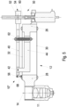
- FIG. 1 shows schematically the structure of a first embodiment of a device 10 for moving an optical element, namely in this case a microscope optics 11 along the optical axis 14 of a microscope 16.
- a microscope optics 11 along the optical axis 14 of a microscope 16.
- further elements of this microscope are a slide 18, a detector 20 and a display 22 is shown schematically.
- the microscope 16 is, for example, an automated fluorescence microscope for counting bacteria, cells or microparticles on slides, membranes and/or counting chambers. The precise construction of the microscope and its intended use are not critical to the apparatus 10 of the present invention.
- the device 10 has a parallelogram guide unit 12 which has an attachment element 26 to be fixed in the microscope and a holding element 28 holding the microscope optics 11 .
- Two leaf springs 30, 32 extend between the two as connecting arms 34, 36.
- the leaf springs 30, 32 are firmly fixed to the attachment element 26 and the holding element 28.
- the parallelogram guide unit 12 forms a parallel crank mechanism 38.
- this parallel crank mechanism 38 is expanded by an adjusting lever 40 .
- the adjusting lever 40 has a bearing point 42 at which it is rotatably mounted on an arm 44 which is L-shaped in this exemplary embodiment and which in turn protrudes from the attachment element 26 in this example.
- the bearing point 42 and thus the pivot bearing 46 are located quite close to the microscope optics holding element 28.
- At this bearing point 42 is also one end 48 of the adjusting lever 40, the other End 50 is in operative connection with an adjustment drive 52 and thus has an adjustment point 54 .
- At the above-mentioned end 48 of the adjusting lever 40 there is a coupling point 56 which is used for the operative connection of the adjusting lever 40 to the holding element 28 .
- the operative connection is realized in this exemplary embodiment by a leaf spring 58 which is firmly clamped at its ends and is connected on the one hand to the adjustment lever 40 and on the other hand to the holding element 28 .
- the adjustment drive 52 is designed as a spindle drive 60 in this exemplary embodiment. Between the adjustment lever 40 and the attachment element 26 there is a tension spring 62 which prevents the adjustment drive 52 from playing relative to the adjustment lever 40 .
- the parallelogram guide unit 12 ie the parallel crank mechanism 38 with the adjusting lever 40, is shown again in perspective. While this unit in the Figs. 1 and 2 is shown in its initial position 3 the parallel crank mechanism 38 with the pivoted adjusting lever and thus the holding element 28 for the microscope optics 11 in its deflected position. It can be seen that the alignment of the microscope optics 11 remains parallel to the optical axis, with the microscope optics 11 being moved laterally offset from the optical axis during the adjustment, but this is not critical for the examinations to be carried out in the microscope.
- FIGS Figs. 1 to 3 A second embodiment of the device 10' is shown. As far as the in 4 shown individual elements of the device 10 'are identical or similar in construction or function to those of the device 10, they are in 4 with the same reference numbers as in FIGS Figs. 1 to 3 marked.
- the difference between the device 10' and the device 10 is the design of the operative connection between the coupling point 56 of the adjusting lever 40 with the microscope holding element 28.
- a plunger 64 is located between the two.
- a tension spring 66 is provided, which also acts between the adjusting lever 40 and the holding element 28 .
- the retaining element 28 is tensioned against the adjustment lever 40 by the tension spring 66 .
- FIG 5 another exemplary embodiment of the adjusting device 10" is shown. It also applies here that the in figure 5 shown details of the device 10 "in this respect with the same reference numerals as in the Figs. 1 to 3 are marked as they show structurally or functionally identical or similar parts.
- figure 5 the mechanical coupling between the adjusting lever 40 and the holding element 28 is realized by a link 68 which is articulated at both ends to the end 48 of the adjusting lever 40 on the one hand and to the holding element 28 on the other hand.
- the parallel crank mechanism 38 can be deflected or adjusted by the smallest distances, as is particularly advantageous when used as a device for moving an optical element of a microscope.
- the possible games are compensated for on the one hand by the springs 62 and, if present, 66 and on the other hand prevented by the use of a solid joint in particular.
- the leaf spring 58 in the device 10 is used as a solid-state joint 1 to see. If this leaf spring is made of shape memory alloy material, the elastic range of the leaf spring can be significantly increased compared to spring steel material. In connection with shape memory alloys, one also speaks of "superelasticity".
Landscapes
- Physics & Mathematics (AREA)
- Chemical & Material Sciences (AREA)
- Analytical Chemistry (AREA)
- General Physics & Mathematics (AREA)
- Optics & Photonics (AREA)
- Microscoopes, Condenser (AREA)
Description
- Die Erfindung betrifft eine Vorrichtung zur Bewegung eines optischen Elements entlang der optischen Achse eines Mikroskops.
- Bei Mikroskopen, insbesondere bei automatisch arbeitenden Mikroskopen muss die Mikroskopoptik längs der optischen Achse bewegbar ausgeführt sein. Dazu wird eine vorzugsweise einachsige Führung mit Antrieb benötigt. Die Bewegung sollte in sehr kleinen Schritten erfolgen können. Das System sollte ferner eine hohe Funktionalität bei niedrigen Kosten aufweisen.
- Im Stand der Technik sind Parallelogramm-Führungseinheiten für optische Elemente bei Mikroskopen bekannt, bei denen mit Blattfedern gearbeitet wird. Beispiele hierfür sind in
EP-B-2 120 080 undUS-B-8 964 287 beschrieben.US-B-9 201 234 -
DE-U-201 06 831 zeigt eine Vorrichtung zur Feinpositionierung mit einem Doppelparallel-Federelement, das einen Rahmen, zwei Seitenbalken und einen Mittelbalken aufweist, wobei als Antriebselement ein Piezoelement mit integrierter Hebelübersetzung vorgesehen ist. - Mit den bekannten Systemen lässt sich die Mikroskopoptik nur mit recht großem Aufwand "feinfühlig" bewegen.
- Aufgabe der Erfindung ist es, eine Vorrichtung zur Bewegung eines optischen Elements entlang der optischen Achse eines Mikroskops zu schaffen, bei der die Bewegung in kleinsten Schritten bzw. um kleinste Distanzen erfolgen kann.
- Zur Lösung dieser Aufgabe wird mit der Erfindung eine Vorrichtung zur Bewegung eines optischen Elements entlang der optischen Achse eines Mikroskops vorgeschlagen, die versehen ist mit den Merkmalen des Anspruchs 1.
- Einzelne Ausgestaltungen der Erfindung sind Gegenstand der Unteransprüche.
- Bei der erfindungsgemäßen Vorrichtung wird eine Parallelogramm-Führungseinheit für das optische Element eingesetzt. Diese Parallelogramm-Führungseinheit ist im Mikroskop verbaut und weist ein Anbringungselement auf, zu dem beabstandet ein Halteelement angeordnet ist. Das Halteelement dient der Halterung des zu verstellenden optischen Elements. Anbringungselement und Halteelement sind durch zwei Verbindungsarme miteinander verbunden, wobei die gesamte Anordnung gelenkig bzw. beweglich und als Parallelogramm-Führungseinheit ausgeführt ist.
- Erfindungsgemäß wird nun mittels eines Kurbelgetriebes auf diese Parallelogramm-Führungseinheit mittels eines Verstellhebels, der drehbar gelagert ist, eingewirkt, wodurch insgesamt ein Parallelkurbelgetriebe mit Verstellhebel gegeben ist. Der verschwenkbare Verstellhebel weist einen Lagerpunkt auf, an dem er drehbar gelagert ist. An einem Punkt des Verstellhebels, beispielsweise an seinem einen Ende, ist der Verstellhebel mit dem Halteelement gekoppelt (Koppelpunkt), während er an einem zweiten Punkt, nämlich dem Verstellpunkt, mit einem Verstellantrieb in Wirkverbindung steht. Hierzu weist das Anbringungselement einen sich in Richtung auf das Halteelement erstreckenden Lagerarm mit einem Drehlager für den Lagerpunkt des Verstellhebels auf, wobei das Drehlager des Lagerarms außerhalb des von der Parallelogramm-Führungseinheit eingenommenen Bereichs liegt.
- Das Verstellhebel-Untersetzungsverhältnis wird bestimmt durch die Relativlage von Koppelpunkt, Verstellpunkt und Lagerpunkt des Verstellhebels.
- In weiterer zweckmäßiger Ausgestaltung der Erfindung kann vorgesehen sein, dass die Verbindungsarme der Parallelogramm-Führungseinheit als Blattfedern ausgebildet sind, die an ihren Enden jeweils fest mit dem Anbringungselement und dem Halteelement verbunden sind. Dies hat den Vorteil, dass sich die Parallelogramm-Führungseinheit nach einer Auslenkung selbstständig in die Grundstellung zurückbewegt, und zwar in Folge der Blattfedern. Die Zurückbewegung in die Grundstellung erfolgt an sich über den Verstellantrieb, so dass die Blattfedern insoweit unterstützend wirken.
- In weiterer zweckmäßiger Ausgestaltung der Erfindung kann vorgesehen sein, dass die Wirkverbindung zwischen dem Koppelpunkt des Verstellhebels und dem Halteelement als beweglich mit beiden verbundener Lenker ausgebildet ist.
- Bei der zuvor genannten Variante ist es insbesondere von Vorteil, wenn der Lenker als Blattfeder aus einem Federstahlmaterial oder aus einem Formgedächtnislegierungs-Material ausgebildet ist, wobei die Blattfeder an ihren Enden fest mit dem Verstellhebel und dem Halteelement verbunden ist. Die Blattfeder, die den Lenker und damit die Kopplung zwischen Koppelpunkt des Verstellhebels mit dem Halteelement bildet, ist derart flexibel, so dass die tolerierbaren Bewegungen zum Verstellen der Parallelogramm-Führungseinheit in zuverlässiger Weise realisiert werden können. Überdies handelt es sich bei der Realisierung des Lenkers durch eine Blattfeder um eine spielfreie Ausführung der Wirkverbindung zwischen Verstellhebel und Halteelement. Wird als Material für die Blattfeder eine Formgedächtnislegierung verwendet, so ist die Elastizität der Blattfeder gegenüber Federstahl deutlich erhöht.
- In weiterer vorteilhafter Ausgestaltung und Alternative zur Ausbildung eines Lenkers als Blattfeder kann die Wirkverbindung zwischen Verstellhabel und Halteelement auch dadurch bewirkt werden, dass der Verstellhebel an dem Halteelement anliegt, und zwar insbesondere an seinem einen Ende z. B. einen Stößel aufweist, der mit abgerundetem Ende auf das Halteelement einwirkt. Alternativ kann das Halteelement eine sphärische Kontaktfläche für den Verstellhebel aufweisen. Durch die sphärische Ausführung mindestens eines der beiden aneinanderliegenden Elemente (Verstellhebel (bzw. Stößel) und Halteelement) "rollen" sich beide gegeneinander ab, wenn der Verstellhebel verstellt wird. Bei dieser Ausgestaltung der Erfindung kann es von Vorteil sein, den Verstellhebel mittels einer Feder mit dem Halteelement zu verspannen, d. h. federnd zu verbinden (auf Zug), damit eventuelle Spiele minimiert bzw. verringert werden.
- Insbesondere von Vorteil ist es, wenn der Verstellantrieb als Spindelantrieb oder Linearaktuator ausgeführt ist.
- Die Erfindung wird nachfolgend anhand mehrerer Ausführungsbeispiele und unter Bezugnahme auf die Zeichnung näher erläutert. Im Einzelnen zeigen:
- Fig. 1
- eine Schnittansicht der Parallelogramm-Führungseinheit mit um diese herum schematisch angedeuteten Elementen eines Mikroskops,
- Fig. 2
- eine perspektivische Ansicht der Parallelogramm-Führungseinheit nach
Fig. 1 , - Fig. 3
- eine Schnittansicht der Parallelogramm-Führungseinheit gemäß
Fig. 1 , jedoch im Zustand der Verstellung des Verstellhebels, - Fig. 4
- eine alternative Ausführung einer Vorrichtung zur Bewegung eines optischen Elements, wobei die Parallelogramm-Führungseinheit einen Stößel zwischen Verstellhebel und Mikroskopoptik-Halteelement aufweist und
- Fig. 5
- eine alternative Ausführung einer Vorrichtung zur Bewegung eines optischen Elements, wobei der Verstellhebel mittels eines gelenkig gelagerten starren Lenkers mit dem Mikroskopoptik-Halteelement verbunden ist.
-
Fig. 1 zeigt schematisch den Aufbau eines ersten Ausführungsbeispiels einer Vorrichtung 10 zur Bewegung eines optischen Elements, nämlich in diesem Fall einer Mikroskopoptik 11 entlang der optischen Achse 14 eines Mikroskops 16. Als weitere Elemente dieses Mikroskops sind der Einfachheit halber noch ein Objektträger 18, ein Detektor 20 und eine Anzeige 22 schematisch gezeigt. Bei dem Mikroskop 16 handelt es sich beispielsweise um ein automatisiertes Fluoreszenzmikroskop zum Zählen von Bakterien, Zellen oder Mikropartikeln auf Objektträgern, Membranen und/oder Zählkammern. Die genaue Konstruktion des Mikroskops und sein Einsatzzweck sind für die erfindungsgemäße Vorrichtung 10 nicht entscheidend. - Die Vorrichtung 10 weist eine Parallelogramm-Führungseinheit 12 auf, die ein im Mikroskop zu fixierendes Anbringungselement 26 und ein die Mikroskopoptik 11 haltendes Halteelement 28 aufweist. Zwischen beiden erstrecken sich zwei Blattfedern 30, 32 als Verbindungsarme 34, 36. Die Blattfedern 30, 32 sind fest an dem Anbringungselement 26 und dem Halteelement 28 fixiert. Insoweit bildet die Parallelogramm-Führungseinheit 12 ein Parallelkurbelgetriebe 38.
- Erfindungsgemäß ist nun dieses Parallelkurbelgetriebe 38 um einen Verstellhebel 40 erweitert. Der Verstellhebel 40 weist einen Lagerpunkt 42 auf, an dem er an einem in diesem Ausführungsbeispiel L-förmigen Arm 44 drehbar gelagert ist, der seinerseits in diesem Beispiel vom Anbringungselement 26 absteht. Der Lagerpunkt 42 und damit das Drehlager 46 befinden sich dabei recht nahe an dem Mikroskopoptik-Halteelement 28. An diesem Lagerpunkt 42 befindet sich ferner das eine Ende 48 des Verstellhebels 40, dessen anderes Ende 50 in Wirkverbindung mit einem Verstellantrieb 52 steht und somit einen Verstellpunkt 54 aufweist. Am zuvor genannten Ende 48 des Verstellhebels 40 befindet sich ein Koppelpunkt 56, der der Wirkverbindung des Verstellhebels 40 mit dem Halteelement 28 dient. Die Wirkverbindung wird in diesem Ausführungsbeispiel durch eine Blattfeder 58 realisiert, die fest eingespannt an ihren Enden einerseits mit dem Verstellhebel 40 und andererseits mit dem Halteelement 28 verbunden ist.
- Der Verstellantrieb 52 ist in diesem Ausführungsbeispiel als Spindelantrieb 60 ausgebildet. Zwischen dem Verstellhebel 40 und dem Anbringungselement 26 befindet sich eine Zugfeder 62, die die Entstehung eines Spiels des Verstellantriebs 52 relativ zum Verstellhebel 40 verhindert.
- In
Fig. 2 ist die Parallelogramm-Führungseinheit 12, d. h. das Parallelkurbelgetriebe 38 mit Verstellhebel 40 nochmals perspektivisch dargestellt. Während diese Einheit in denFign. 1 und2 in ihrer Ausgangsstellung gezeigt ist, zeigtFig. 3 das Parallelkurbelgetriebe 38 mit verschwenktem Verstellhebel und damit das Halteelement 28 für die Mikroskopoptik 11 in seiner ausgelenkten Stellung. Zu erkennen ist, dass die Ausrichtung der Mikroskopoptik 11 parallel zur optischen Achse verbleibt, wobei die Mikroskopoptik 11 beim Verstellen seitlich versetzt zur optischen Achse bewegt wird, was aber für die im Mikroskop durchzuführenden Untersuchungen unkritisch ist. - In
Fig. 4 ist ein zweites Ausführungsbeispiel der Vorrichtung 10' gezeigt. Soweit die inFig. 4 gezeigten Einzelelemente der Vorrichtung 10' mit denjenigen der Vorrichtung 10 konstruktions- bzw. funktionsgleich bzw. -ähnlich sind, sind sie inFig. 4 mit den gleichen Bezugszeichen wie in denFign. 1 bis 3 gekennzeichnet. - Der Unterschied der Vorrichtung 10' gegenüber der Vorrichtung 10 besteht in der Ausbildung der Wirkverbindung zwischen dem Koppelpunkt 56 des Verstellhebels 40 mit dem Mikroskop-Halteelement 28. Im Ausführungsbeispiel gemäß
Fig. 4 befindet sich zwischen beiden ein Stößel 64. Zusätzlich ist eine Zugfeder 66 vorgesehen, die ebenfalls zwischen dem Verstellhebel 40 und dem Halteelement 28 wirkt. Durch die Zugfeder 66 wird das Halteelement 28 gegen den Verstellhebel 40 gespannt. Dadurch wird ein potentielles Spiel bei der Verstellung des Verstellhebels 40 und dessen Einwirkung auf das Halteelement 28 unterdrückt. - In
Fig. 5 ist ein weiteres Ausführungsbeispiel der Verstellvorrichtung 10" gezeigt. Auch hier gilt, dass die inFig. 5 gezeigten Einzelheiten der Vorrichtung 10" insoweit mit den gleichen Bezugszeichen wie in denFign. 1 bis 3 gekennzeichnet sind, wie sie konstruktiv bzw. funktional gleiche bzw. ähnliche Teile zeigen. - Anstelle der Blattfeder bei der Vorrichtung 10 der
Fign. 1 bis 3 wird bei dem Ausführungsbeispiel der Vorrichtung 10" nachFig. 5 die mechanische Kopplung zwischen Verstellhebel 40 und Halteelement 28 durch einen Lenker 68 realisiert, der an seinen beiden Enden gelenkig mit einerseits dem Ende 48 des Verstellhebels 40 und andererseits mit dem Halteelement 28 verbunden ist. - Durch den erfindungsgemäß vorgesehenen Verstellhebel 40, dessen Untersetzungsverhältnis durch die in
Fig. 1 mit L1 und L2 bezeichneten Längen definiert ist, lässt sich das Parallelkurbelgetriebe 38 um kleinste Distanzen auslenken bzw. verstellen, wie es insbesondere in der Anwendung als Vorrichtung zum Bewegen eines optischen Elements eines Mikroskops von Vorteil ist. Die möglichen Spiele werden einerseits durch die Federn 62 und, sofern vorhanden, 66 ausgeglichen und andererseits durch die Verwendung insbesondere eines Festkörpergelenks unterbunden. Als Festkörpergelenk ist insbesondere die Blattfeder 58 bei der Vorrichtung 10 nachFig. 1 zu sehen. Wenn diese Blattfeder aus Formgedächtnislegierungsmaterial hergestellt ist, lässt sich der elastische Bereich der Blattfeder gegenüber Federstahlmaterial deutlich erweitern. Man spricht im Zusammenhang mit Formgedächtnislegierungen auch von "Superelastizität". -
- 10
- Verstellvorrichtung
- 10'
- Verstellvorrichtung
- 10"
- Verstellvorrichtung
- 11
- Mikroskopoptik
- 12
- Parallelogramm-Führungseinheit
- 14
- Achse
- 16
- Mikroskop
- 18
- Objektträger
- 20
- Detektor
- 22
- Anzeige
- 26
- Anbringungselement
- 28
- Mikroskopoptik-Halteelement
- 30
- Blattfedern
- 32
- Blattfedern
- 34
- Verbindungsarm
- 36
- Verbindungsarm
- 38
- Parallelkurbelgetriebe
- 40
- Verstellhebel
- 42
- Lagerpunkt
- 44
- Arm
- 46
- Drehlager
- 48
- Ende
- 50
- Ende
- 52
- Verstellantrieb
- 54
- Verstellpunkt
- 56
- Koppelpunkt
- 58
- Blattfeder
- 60
- Spindelantrieb
- 62
- Zugfeder
- 64
- Stößel
- 66
- Zugfeder
- 68
- Lenker
Claims (6)
- Vorrichtung zur Bewegung eines optischen Elements entlang der optischen Achse eines Mikroskops, mit- einer Parallelogramm-Führungseinheit (12) für das optische Element mit einem Anbringungselement (26) zur Montage in einem Mikroskop (16) oder als Teil eines Mikroskops (16) und mit einem von dem Anbringungselemente (26) beabstandeten Halteelement (28) für das optische Element des Mikroskops (16), wobei das Anbringungselement (26) und das Halteelement (28) durch zwei Verbindungsarme (34, 36) der Parallelogramm-Führungseinheit (12) verbunden sind, die an ihren Enden an dem Anbringungselement (26) und dem Halteelement (28) angeordnet sind,- einem verschwenkbaren Verstellhebel (40) mit einem Lagerpunkt (42), an dem der Verstellhebel (40) drehbar gelagert ist, und- einem Verstellantrieb (52) zum Verdrehen des Verstellhebels (40) um seinen Lagerpunkt (42),- wobei der Verstellhebel (40) einen Koppelpunkt (56), an dem der Verstellhebel (40) zur Bewegung des Halteelements (28) mit diesem in Wirkverbindung steht, und einen Verstellpunkt (54) aufweist, an dem der Verstellhebel (40) mit dem Verstellantrieb (52) in Wirkverbindung steht,dadurch gekennzeichnet,- dass der Lagerpunkt (42) des Verstellhebels (40) zwischen dessen Koppelpunkt (56) und dessen Verstellpunkt (54) angeordnet ist und der Abstand L2 vom Verstellpunkt (54) zum Lagerpunkt (42) und der Abstand L1 vom Koppelpunkt (56) zum Lagerpunkt (42) ein Verstellhebel-Untersetzungsverhältnis aus dem Verschwenkweg des Verstellhebels (40) an dessen Verstellpunkt (54) zu dem Verschwenkweg des Verstellhebels (40) an dessen Koppelpunkt (56) definieren und- dass das Anbringungselement (26) einen sich in Richtung auf das Halteelement (28) erstreckenden Lagerarm (44) mit einem Drehlager (46) für den Lagerpunkt (42) des Verstellhebels (40) aufweist, wobei das Drehlager (46) des Lagerarms (44) außerhalb des von der Parallelogramm-Führungseinheit (12) eingenommenen Bereichs liegt.
- Vorrichtung nach Anspruch 1, dadurch gekennzeichnet, dass die Verbindungsarme (34, 36) der Parallelogramm-Führungseinheit (12) als Blattfedern (30, 32) ausgebildet sind, die an ihren Enden jeweils fest eingespannt mit dem Anbringungselement (26) und dem Halteelement (28) verbunden sind.
- Vorrichtung nach Anspruch 1 oder 2, dadurch gekennzeichnet, dass die Wirkverbindung zwischen dem Koppelpunkt (56) des Verstellhebels (40) und dem Halteelement (28) als beweglich mit beiden verbundener Lenker (68) ausgebildet ist.
- Vorrichtung nach Anspruch 3, dadurch gekennzeichnet, dass der Lenker (68) als Blattfeder (58) aus einem Federstahlmaterial oder aus einem Formgedächtnislegierungs-Material ausgebildet ist, wobei die Blattfeder (58) an ihren Enden fest eingespannt mit dem Verstellhebel (40) und dem Halteelement (28) verbunden ist.
- Vorrichtung nach einem der Ansprüche 1 bis 3, dadurch gekennzeichnet, dass die Wirkverbindung zwischen dem Koppelpunkt (56) des Verstellhebels (40) und dem Halteelement (28) durch Anlage des Verstellhebels (40) an dem Halteelement (28), insbesondere durch Anlage des einen Endes des Verstellhebels (40) an dem Halteelement (28) ausgebildet ist.
- Vorrichtung nach einem der Ansprüche 1 bis 5, dadurch gekennzeichnet, dass der Verstellantrieb (52) als Spindelantrieb (60) oder Linearaktuator ausgeführt ist.
Priority Applications (1)
| Application Number | Priority Date | Filing Date | Title |
|---|---|---|---|
| EP17180546.8A EP3428708B1 (de) | 2017-07-10 | 2017-07-10 | Vorrichtung zur bewegung eines optischen elements entlang der optischen achse eines mikroskops |
Applications Claiming Priority (1)
| Application Number | Priority Date | Filing Date | Title |
|---|---|---|---|
| EP17180546.8A EP3428708B1 (de) | 2017-07-10 | 2017-07-10 | Vorrichtung zur bewegung eines optischen elements entlang der optischen achse eines mikroskops |
Publications (2)
| Publication Number | Publication Date |
|---|---|
| EP3428708A1 EP3428708A1 (de) | 2019-01-16 |
| EP3428708B1 true EP3428708B1 (de) | 2023-05-17 |
Family
ID=59313126
Family Applications (1)
| Application Number | Title | Priority Date | Filing Date |
|---|---|---|---|
| EP17180546.8A Active EP3428708B1 (de) | 2017-07-10 | 2017-07-10 | Vorrichtung zur bewegung eines optischen elements entlang der optischen achse eines mikroskops |
Country Status (1)
| Country | Link |
|---|---|
| EP (1) | EP3428708B1 (de) |
Families Citing this family (1)
| Publication number | Priority date | Publication date | Assignee | Title |
|---|---|---|---|---|
| EP3757644A1 (de) * | 2019-06-26 | 2020-12-30 | Paris Sciences et Lettres - Quartier Latin | Verformbare vorrichtung zur positionierung eines halters |
Family Cites Families (9)
| Publication number | Priority date | Publication date | Assignee | Title |
|---|---|---|---|---|
| JPH11271631A (ja) * | 1998-03-25 | 1999-10-08 | Jeol Ltd | 光学顕微鏡を組み込んだ走査型電子顕微鏡 |
| DE20106831U1 (de) * | 2001-04-19 | 2001-09-27 | Leica Microsystems Wetzlar GmbH, 35578 Wetzlar | Vorrichtung zur Feinpositionierung |
| DE20106834U1 (de) * | 2001-04-19 | 2001-06-28 | Leica Microsystems Wetzlar GmbH, 35578 Wetzlar | Vorrichtung zur Feinfokussierung |
| DE102008007773A1 (de) * | 2008-02-06 | 2009-08-13 | Carl Zeiss Microimaging Gmbh | Feintrieb für Objektive, insbesondere für Mikroskope |
| US8319829B2 (en) | 2008-05-16 | 2012-11-27 | Ffei Limited | Method and system for controlling the position of a microscope lens |
| US7733586B2 (en) * | 2008-05-16 | 2010-06-08 | Ffei Limited | Lens positioning assembly |
| EP2630537B1 (de) | 2010-10-22 | 2018-12-12 | Motic China Group Co., Ltd. | Fokussierungseinheit und automatisiertes Objektträger-Scannersystem damit |
| DE102010060841B3 (de) | 2010-11-26 | 2012-06-06 | Leica Microsystems Cms Gmbh | Einrichtung zum Fokussieren eines Mikroskopobjektivs auf eine Probe |
| DE102011121928B4 (de) * | 2011-08-01 | 2015-03-05 | Physik Instrumente (Pi) Gmbh & Co. Kg | Anordnung zum Betreiben eines dynamischen Nanofokussiersystems |
-
2017
- 2017-07-10 EP EP17180546.8A patent/EP3428708B1/de active Active
Also Published As
| Publication number | Publication date |
|---|---|
| EP3428708A1 (de) | 2019-01-16 |
Similar Documents
| Publication | Publication Date | Title |
|---|---|---|
| EP1577693B1 (de) | Objektiv mit wenigstens einem optischen Element | |
| WO2007087817A1 (de) | Permanentkontaktmechanik | |
| DE102018106012B3 (de) | Justierbare Spiegelbaugruppe mit Blattfederelement | |
| EP2135124B1 (de) | Optikfassung und optisches bauelement mit einer derartigen optikfassung | |
| DE102007042260B4 (de) | Objektivwechsler und ein Mikroskop | |
| DE102007030579B4 (de) | Lateral verstellbare Fassung für optische Elemente | |
| EP3428708B1 (de) | Vorrichtung zur bewegung eines optischen elements entlang der optischen achse eines mikroskops | |
| EP1485762A2 (de) | Vorrichtung zur manipulation der winkellage eines gegenstands gegen ber einer festen struktur | |
| DE102018127469A1 (de) | Positioniereinheit und Beobachtungsvorrichtung | |
| DE102020104784A1 (de) | Justierfassung zur radialen Justierung einer optischen Einheit mit einer optischen Achse | |
| DE102007032088A1 (de) | Vorschubeinrichtung für einen Mehrkoordinaten-Messtisch und Verfahren zur Steuerung einer derartigen Vorschubeinrichtung | |
| DE202011052291U1 (de) | Vorrichtung zur Materialbearbeitung mittels eines Laserstrahles | |
| EP2436557B1 (de) | Verstellvorrichtung zum Verstellen eines optisch relevanten Bauteils eines Fahrzeugscheinwerfers | |
| DE1926711B2 (de) | Maschine zum Behandeln von Vorgespinst bzw. Garn | |
| DE102009055402A1 (de) | Linearer Führungsmechanismus und Messvorrichtung | |
| DE102014106316B3 (de) | Objektiv mit einer lateral justierbaren Linse | |
| AT413576B (de) | Einrichtung zum verschliessen einer öffnung | |
| DE202010007985U1 (de) | Optik-Halter | |
| DE102010033024A1 (de) | Fadenführer für eine Flachstrickmaschine | |
| EP1162489B1 (de) | Fokussiertrieb für optische Instrumente | |
| WO2007014621A1 (de) | Haltemodul, das eine festkörperimmersionslinse trägt | |
| DE102018116570B3 (de) | Vorrichtung zur variierbaren Beeinflussung der Wellenfront eines Strahlenbündels mit einer über deren Rückseite deformierbaren Planoptik | |
| DE202024105171U1 (de) | Düsenanordnung und 3D-Druckvorrichtung | |
| DE3114238A1 (de) | Einstellbare bandfuehrung fuer aufnahme- und/oder wiedergabesysteme mit spiralabtastung | |
| WO2003075071A1 (de) | Vorrichtung zum umschalten eines schwenkbaren halters |
Legal Events
| Date | Code | Title | Description |
|---|---|---|---|
| PUAI | Public reference made under article 153(3) epc to a published international application that has entered the european phase |
Free format text: ORIGINAL CODE: 0009012 |
|
| STAA | Information on the status of an ep patent application or granted ep patent |
Free format text: STATUS: THE APPLICATION HAS BEEN PUBLISHED |
|
| AK | Designated contracting states |
Kind code of ref document: A1 Designated state(s): AL AT BE BG CH CY CZ DE DK EE ES FI FR GB GR HR HU IE IS IT LI LT LU LV MC MK MT NL NO PL PT RO RS SE SI SK SM TR |
|
| AX | Request for extension of the european patent |
Extension state: BA ME |
|
| STAA | Information on the status of an ep patent application or granted ep patent |
Free format text: STATUS: REQUEST FOR EXAMINATION WAS MADE |
|
| 17P | Request for examination filed |
Effective date: 20190716 |
|
| RBV | Designated contracting states (corrected) |
Designated state(s): AL AT BE BG CH CY CZ DE DK EE ES FI FR GB GR HR HU IE IS IT LI LT LU LV MC MK MT NL NO PL PT RO RS SE SI SK SM TR |
|
| STAA | Information on the status of an ep patent application or granted ep patent |
Free format text: STATUS: EXAMINATION IS IN PROGRESS |
|
| 17Q | First examination report despatched |
Effective date: 20201015 |
|
| REG | Reference to a national code |
Ref country code: DE Ref legal event code: R079 Ref document number: 502017014720 Country of ref document: DE Free format text: PREVIOUS MAIN CLASS: G02B0021240000 Ipc: G02B0007000000 |
|
| GRAP | Despatch of communication of intention to grant a patent |
Free format text: ORIGINAL CODE: EPIDOSNIGR1 |
|
| STAA | Information on the status of an ep patent application or granted ep patent |
Free format text: STATUS: GRANT OF PATENT IS INTENDED |
|
| RIC1 | Information provided on ipc code assigned before grant |
Ipc: G02B 21/24 20060101ALI20221103BHEP Ipc: G02B 7/00 20060101AFI20221103BHEP |
|
| INTG | Intention to grant announced |
Effective date: 20221129 |
|
| RIN1 | Information on inventor provided before grant (corrected) |
Inventor name: MIETHE, PETER Inventor name: CORRENS, NICO Inventor name: HENZE, STEPHAN Inventor name: HEILEMANN, WOLFGANG |
|
| GRAS | Grant fee paid |
Free format text: ORIGINAL CODE: EPIDOSNIGR3 |
|
| GRAA | (expected) grant |
Free format text: ORIGINAL CODE: 0009210 |
|
| STAA | Information on the status of an ep patent application or granted ep patent |
Free format text: STATUS: THE PATENT HAS BEEN GRANTED |
|
| AK | Designated contracting states |
Kind code of ref document: B1 Designated state(s): AL AT BE BG CH CY CZ DE DK EE ES FI FR GB GR HR HU IE IS IT LI LT LU LV MC MK MT NL NO PL PT RO RS SE SI SK SM TR |
|
| REG | Reference to a national code |
Ref country code: GB Ref legal event code: FG4D Free format text: NOT ENGLISH |
|
| REG | Reference to a national code |
Ref country code: CH Ref legal event code: EP |
|
| REG | Reference to a national code |
Ref country code: DE Ref legal event code: R096 Ref document number: 502017014720 Country of ref document: DE |
|
| REG | Reference to a national code |
Ref country code: IE Ref legal event code: FG4D Free format text: LANGUAGE OF EP DOCUMENT: GERMAN |
|
| REG | Reference to a national code |
Ref country code: AT Ref legal event code: REF Ref document number: 1568614 Country of ref document: AT Kind code of ref document: T Effective date: 20230615 |
|
| REG | Reference to a national code |
Ref country code: LT Ref legal event code: MG9D |
|
| REG | Reference to a national code |
Ref country code: NL Ref legal event code: MP Effective date: 20230517 |
|
| PG25 | Lapsed in a contracting state [announced via postgrant information from national office to epo] |
Ref country code: SE Free format text: LAPSE BECAUSE OF FAILURE TO SUBMIT A TRANSLATION OF THE DESCRIPTION OR TO PAY THE FEE WITHIN THE PRESCRIBED TIME-LIMIT Effective date: 20230517 Ref country code: PT Free format text: LAPSE BECAUSE OF FAILURE TO SUBMIT A TRANSLATION OF THE DESCRIPTION OR TO PAY THE FEE WITHIN THE PRESCRIBED TIME-LIMIT Effective date: 20230918 Ref country code: NO Free format text: LAPSE BECAUSE OF FAILURE TO SUBMIT A TRANSLATION OF THE DESCRIPTION OR TO PAY THE FEE WITHIN THE PRESCRIBED TIME-LIMIT Effective date: 20230817 Ref country code: NL Free format text: LAPSE BECAUSE OF FAILURE TO SUBMIT A TRANSLATION OF THE DESCRIPTION OR TO PAY THE FEE WITHIN THE PRESCRIBED TIME-LIMIT Effective date: 20230517 Ref country code: ES Free format text: LAPSE BECAUSE OF FAILURE TO SUBMIT A TRANSLATION OF THE DESCRIPTION OR TO PAY THE FEE WITHIN THE PRESCRIBED TIME-LIMIT Effective date: 20230517 |
|
| PG25 | Lapsed in a contracting state [announced via postgrant information from national office to epo] |
Ref country code: RS Free format text: LAPSE BECAUSE OF FAILURE TO SUBMIT A TRANSLATION OF THE DESCRIPTION OR TO PAY THE FEE WITHIN THE PRESCRIBED TIME-LIMIT Effective date: 20230517 Ref country code: PL Free format text: LAPSE BECAUSE OF FAILURE TO SUBMIT A TRANSLATION OF THE DESCRIPTION OR TO PAY THE FEE WITHIN THE PRESCRIBED TIME-LIMIT Effective date: 20230517 Ref country code: LV Free format text: LAPSE BECAUSE OF FAILURE TO SUBMIT A TRANSLATION OF THE DESCRIPTION OR TO PAY THE FEE WITHIN THE PRESCRIBED TIME-LIMIT Effective date: 20230517 Ref country code: LT Free format text: LAPSE BECAUSE OF FAILURE TO SUBMIT A TRANSLATION OF THE DESCRIPTION OR TO PAY THE FEE WITHIN THE PRESCRIBED TIME-LIMIT Effective date: 20230517 Ref country code: IS Free format text: LAPSE BECAUSE OF FAILURE TO SUBMIT A TRANSLATION OF THE DESCRIPTION OR TO PAY THE FEE WITHIN THE PRESCRIBED TIME-LIMIT Effective date: 20230917 Ref country code: HR Free format text: LAPSE BECAUSE OF FAILURE TO SUBMIT A TRANSLATION OF THE DESCRIPTION OR TO PAY THE FEE WITHIN THE PRESCRIBED TIME-LIMIT Effective date: 20230517 Ref country code: GR Free format text: LAPSE BECAUSE OF FAILURE TO SUBMIT A TRANSLATION OF THE DESCRIPTION OR TO PAY THE FEE WITHIN THE PRESCRIBED TIME-LIMIT Effective date: 20230818 |
|
| PG25 | Lapsed in a contracting state [announced via postgrant information from national office to epo] |
Ref country code: FI Free format text: LAPSE BECAUSE OF FAILURE TO SUBMIT A TRANSLATION OF THE DESCRIPTION OR TO PAY THE FEE WITHIN THE PRESCRIBED TIME-LIMIT Effective date: 20230517 |
|
| PG25 | Lapsed in a contracting state [announced via postgrant information from national office to epo] |
Ref country code: SK Free format text: LAPSE BECAUSE OF FAILURE TO SUBMIT A TRANSLATION OF THE DESCRIPTION OR TO PAY THE FEE WITHIN THE PRESCRIBED TIME-LIMIT Effective date: 20230517 |
|
| PG25 | Lapsed in a contracting state [announced via postgrant information from national office to epo] |
Ref country code: SM Free format text: LAPSE BECAUSE OF FAILURE TO SUBMIT A TRANSLATION OF THE DESCRIPTION OR TO PAY THE FEE WITHIN THE PRESCRIBED TIME-LIMIT Effective date: 20230517 Ref country code: SK Free format text: LAPSE BECAUSE OF FAILURE TO SUBMIT A TRANSLATION OF THE DESCRIPTION OR TO PAY THE FEE WITHIN THE PRESCRIBED TIME-LIMIT Effective date: 20230517 Ref country code: RO Free format text: LAPSE BECAUSE OF FAILURE TO SUBMIT A TRANSLATION OF THE DESCRIPTION OR TO PAY THE FEE WITHIN THE PRESCRIBED TIME-LIMIT Effective date: 20230517 Ref country code: EE Free format text: LAPSE BECAUSE OF FAILURE TO SUBMIT A TRANSLATION OF THE DESCRIPTION OR TO PAY THE FEE WITHIN THE PRESCRIBED TIME-LIMIT Effective date: 20230517 Ref country code: DK Free format text: LAPSE BECAUSE OF FAILURE TO SUBMIT A TRANSLATION OF THE DESCRIPTION OR TO PAY THE FEE WITHIN THE PRESCRIBED TIME-LIMIT Effective date: 20230517 Ref country code: CZ Free format text: LAPSE BECAUSE OF FAILURE TO SUBMIT A TRANSLATION OF THE DESCRIPTION OR TO PAY THE FEE WITHIN THE PRESCRIBED TIME-LIMIT Effective date: 20230517 |
|
| REG | Reference to a national code |
Ref country code: DE Ref legal event code: R097 Ref document number: 502017014720 Country of ref document: DE |
|
| PG25 | Lapsed in a contracting state [announced via postgrant information from national office to epo] |
Ref country code: MC Free format text: LAPSE BECAUSE OF FAILURE TO SUBMIT A TRANSLATION OF THE DESCRIPTION OR TO PAY THE FEE WITHIN THE PRESCRIBED TIME-LIMIT Effective date: 20230517 |
|
| PG25 | Lapsed in a contracting state [announced via postgrant information from national office to epo] |
Ref country code: MC Free format text: LAPSE BECAUSE OF FAILURE TO SUBMIT A TRANSLATION OF THE DESCRIPTION OR TO PAY THE FEE WITHIN THE PRESCRIBED TIME-LIMIT Effective date: 20230517 |
|
| REG | Reference to a national code |
Ref country code: CH Ref legal event code: PL |
|
| REG | Reference to a national code |
Ref country code: BE Ref legal event code: MM Effective date: 20230731 |
|
| PG25 | Lapsed in a contracting state [announced via postgrant information from national office to epo] |
Ref country code: LU Free format text: LAPSE BECAUSE OF NON-PAYMENT OF DUE FEES Effective date: 20230710 |
|
| PLBE | No opposition filed within time limit |
Free format text: ORIGINAL CODE: 0009261 |
|
| STAA | Information on the status of an ep patent application or granted ep patent |
Free format text: STATUS: NO OPPOSITION FILED WITHIN TIME LIMIT |
|
| PG25 | Lapsed in a contracting state [announced via postgrant information from national office to epo] |
Ref country code: LU Free format text: LAPSE BECAUSE OF NON-PAYMENT OF DUE FEES Effective date: 20230710 |
|
| 26N | No opposition filed |
Effective date: 20240220 |
|
| GBPC | Gb: european patent ceased through non-payment of renewal fee |
Effective date: 20230817 |
|
| REG | Reference to a national code |
Ref country code: IE Ref legal event code: MM4A |
|
| PG25 | Lapsed in a contracting state [announced via postgrant information from national office to epo] |
Ref country code: CH Free format text: LAPSE BECAUSE OF NON-PAYMENT OF DUE FEES Effective date: 20230731 |
|
| PG25 | Lapsed in a contracting state [announced via postgrant information from national office to epo] |
Ref country code: SI Free format text: LAPSE BECAUSE OF FAILURE TO SUBMIT A TRANSLATION OF THE DESCRIPTION OR TO PAY THE FEE WITHIN THE PRESCRIBED TIME-LIMIT Effective date: 20230517 |
|
| PG25 | Lapsed in a contracting state [announced via postgrant information from national office to epo] |
Ref country code: SI Free format text: LAPSE BECAUSE OF FAILURE TO SUBMIT A TRANSLATION OF THE DESCRIPTION OR TO PAY THE FEE WITHIN THE PRESCRIBED TIME-LIMIT Effective date: 20230517 Ref country code: IT Free format text: LAPSE BECAUSE OF FAILURE TO SUBMIT A TRANSLATION OF THE DESCRIPTION OR TO PAY THE FEE WITHIN THE PRESCRIBED TIME-LIMIT Effective date: 20230517 Ref country code: FR Free format text: LAPSE BECAUSE OF NON-PAYMENT OF DUE FEES Effective date: 20230717 Ref country code: BE Free format text: LAPSE BECAUSE OF NON-PAYMENT OF DUE FEES Effective date: 20230731 |
|
| PG25 | Lapsed in a contracting state [announced via postgrant information from national office to epo] |
Ref country code: IE Free format text: LAPSE BECAUSE OF NON-PAYMENT OF DUE FEES Effective date: 20230710 |
|
| PG25 | Lapsed in a contracting state [announced via postgrant information from national office to epo] |
Ref country code: GB Free format text: LAPSE BECAUSE OF NON-PAYMENT OF DUE FEES Effective date: 20230817 |
|
| PG25 | Lapsed in a contracting state [announced via postgrant information from national office to epo] |
Ref country code: IE Free format text: LAPSE BECAUSE OF NON-PAYMENT OF DUE FEES Effective date: 20230710 Ref country code: GB Free format text: LAPSE BECAUSE OF NON-PAYMENT OF DUE FEES Effective date: 20230817 |
|
| REG | Reference to a national code |
Ref country code: AT Ref legal event code: MM01 Ref document number: 1568614 Country of ref document: AT Kind code of ref document: T Effective date: 20230710 |
|
| PGFP | Annual fee paid to national office [announced via postgrant information from national office to epo] |
Ref country code: DE Payment date: 20240730 Year of fee payment: 8 |
|
| PG25 | Lapsed in a contracting state [announced via postgrant information from national office to epo] |
Ref country code: AT Free format text: LAPSE BECAUSE OF NON-PAYMENT OF DUE FEES Effective date: 20230710 |
|
| PG25 | Lapsed in a contracting state [announced via postgrant information from national office to epo] |
Ref country code: AT Free format text: LAPSE BECAUSE OF NON-PAYMENT OF DUE FEES Effective date: 20230710 |
|
| PG25 | Lapsed in a contracting state [announced via postgrant information from national office to epo] |
Ref country code: BG Free format text: LAPSE BECAUSE OF FAILURE TO SUBMIT A TRANSLATION OF THE DESCRIPTION OR TO PAY THE FEE WITHIN THE PRESCRIBED TIME-LIMIT Effective date: 20230517 |
|
| PG25 | Lapsed in a contracting state [announced via postgrant information from national office to epo] |
Ref country code: BG Free format text: LAPSE BECAUSE OF FAILURE TO SUBMIT A TRANSLATION OF THE DESCRIPTION OR TO PAY THE FEE WITHIN THE PRESCRIBED TIME-LIMIT Effective date: 20230517 |
|
| PG25 | Lapsed in a contracting state [announced via postgrant information from national office to epo] |
Ref country code: CY Free format text: LAPSE BECAUSE OF FAILURE TO SUBMIT A TRANSLATION OF THE DESCRIPTION OR TO PAY THE FEE WITHIN THE PRESCRIBED TIME-LIMIT; INVALID AB INITIO Effective date: 20170710 |
|
| PG25 | Lapsed in a contracting state [announced via postgrant information from national office to epo] |
Ref country code: HU Free format text: LAPSE BECAUSE OF FAILURE TO SUBMIT A TRANSLATION OF THE DESCRIPTION OR TO PAY THE FEE WITHIN THE PRESCRIBED TIME-LIMIT; INVALID AB INITIO Effective date: 20170710 |
|
| PG25 | Lapsed in a contracting state [announced via postgrant information from national office to epo] |
Ref country code: TR Free format text: LAPSE BECAUSE OF FAILURE TO SUBMIT A TRANSLATION OF THE DESCRIPTION OR TO PAY THE FEE WITHIN THE PRESCRIBED TIME-LIMIT Effective date: 20230517 |