US8319829B2 - Method and system for controlling the position of a microscope lens - Google Patents
Method and system for controlling the position of a microscope lens Download PDFInfo
- Publication number
- US8319829B2 US8319829B2 US12/121,830 US12183008A US8319829B2 US 8319829 B2 US8319829 B2 US 8319829B2 US 12183008 A US12183008 A US 12183008A US 8319829 B2 US8319829 B2 US 8319829B2
- Authority
- US
- United States
- Prior art keywords
- signal
- positional
- microscope lens
- lens
- deviation
- Prior art date
- Legal status (The legal status is an assumption and is not a legal conclusion. Google has not performed a legal analysis and makes no representation as to the accuracy of the status listed.)
- Active, expires
Links
Images


Classifications
-
- G—PHYSICS
- G02—OPTICS
- G02B—OPTICAL ELEMENTS, SYSTEMS OR APPARATUS
- G02B21/00—Microscopes
- G02B21/24—Base structure
- G02B21/241—Devices for focusing
-
- G—PHYSICS
- G02—OPTICS
- G02B—OPTICAL ELEMENTS, SYSTEMS OR APPARATUS
- G02B21/00—Microscopes
- G02B21/36—Microscopes arranged for photographic purposes or projection purposes or digital imaging or video purposes including associated control and data processing arrangements
- G02B21/365—Control or image processing arrangements for digital or video microscopes
- G02B21/367—Control or image processing arrangements for digital or video microscopes providing an output produced by processing a plurality of individual source images, e.g. image tiling, montage, composite images, depth sectioning, image comparison
Definitions
- the present invention relates to a method and a system for controlling the position of a microscope lens.
- the invention relates to applying a small predetermined positional deviation to a reference position of a microscope objective lens.
- the relatively slow or static positioning may involve movements of the order of millimeters on a timescale of tens of seconds; the rapid movement may involve movements of the order of 1 micrometer on a timescale of around 200 microseconds; and the medium motion may involve movements of the order of tens of micrometers over a period of around a few milliseconds to 1 second.
- These movement scales may vary depending upon the size and setup of the microscope apparatus. Each of these movements may be applied individually or may be applied using a composite control signal. Each of the movements must be highly accurate on a micrometer scale in order to accurately focus an image of the sample.
- a method for controlling the position of a microscope lens comprises:
- a positional control signal can be generated to accurately control the position of a microscope objective lens when applying medium or fast position alterations to a substantially static reference position, wherein the substantially static positioning may involve small movements of the order of millimeters on a timescale of tens of seconds when the medium or fast position alterations may respectively involve movements of the order of tens of micrometers over a period of around a few milliseconds to 1 second and movements of the order of 1 micrometer on a timescale of around 200 microseconds. Commonly, such alterations are limited in time and space.
- the generation of a positional control signal involves comparing the measurement signal and the reference signal. Such a comparison may involve an addition or a subtraction. If a modification is made to the measurement signal based on a signal characteristic of the particular effect of the predetermined positional deviation provided by the deviation signal, i.e. a displacement element of the deviation signal, then feedback control to maintain the microscope lens at a reference position can still be used even if medium to fast speed deviations to the reference position are also applied. Typically, such a method will also involve generating the positional control signal using the deviation control signal after the measurement signal has been compared with the reference signal.
- the method may comprise modifying the measurement signal using the deviation signal to produce a modified measurement signal, wherein the measurement signal may be modified based on a predicted displacement signal calculated from the deviation signal.
- Such a method may also comprise comparing the modified measurement signal and the reference signal to produce a comparative signal and summing the comparative signal and the deviation signal to generate the positional control signal.
- the deviation signal may be calculated from a displacement signal, wherein the method may then comprise modifying the measurement signal using the displacement signal to produce a modified measurement signal.
- the modified measurement signal and the reference signal may be compared to produce a comparative signal, wherein said comparative signal and the deviation signal may be summed to generate the positional control signal.
- the microscope lens is coupled to a linear actuator which generates movement along a linear axis.
- This linear actuator may be one of a voice coil actuator a piezoelectric actuator, or a rack and pinion system.
- the optical axis of the lens may be collinear with the axis of motion of the linear actuator.
- the positional control signal is an analogue electrical current signal which is sent to the linear actuator, although this signal may alternatively be an analogue voltage signal or a digital current or voltage signal.
- the control provided by the present invention becomes even more important.
- a constant current must be supplied.
- the presence of natural statistical variations in the current signal supplied to the linear actuator and/or movement of the assembly containing the microscope lens require a comprehensive and accurate control system to maintain a static position.
- the present invention allows scanning operations involving medium to fast motions to be applied without loosing the accuracy of the control system used to maintain a static position.
- a medium speed change in lens position may be representative of a short range scan operation to generate images of a sample with depth.
- the deviation signal may comprise a periodic signal such as a saw-tooth waveform.
- the signal may be provided when using such a medium speed scanning pattern the method of the present invention provides a synergetic effect by accurately controlling any gradual motion and keeping the actual motion of the lens in line with the medium speed components of any deviation waveform.
- the deviation signal may also comprise an impulse signal.
- a system for controlling the position of a microscope lens comprises:
- This system may be adapted to perform the method of the first aspect of the invention or any variation of said method described herein by using a receiver and controller configured as specified above a control system can provide the beneficial effects discussed in relation to the first aspect of the invention.
- the controller may further comprise a comparator for performing a comparison between the measurement signal and the reference signal. This comparison allows a positional control signal to be generated and this positional control signal may be further filtered through a loop composition filter that is provided as part of the controller.
- the controller is configured to modify the measurement signal to generate the positional signal using the deviation signal; the former modification may be based on a signal characteristic of the predicted effect of the predetermined positional deviation, which may be subtracted from the measurement signal before generating the positional control signal, and the controller may also be configured to generate the positional control signal using the deviation signal by adding a signal used to produce the predetermined positional deviation to the positional control signal before sending the positional control signal to set the position of a microscopic lens.
- the receiver and controller may form part of a feedback control system. In other embodiments they may be used as an additional stand along control system.
- the feedback control system may also be integrated with a deviation signal generator for producing a deviation signal and an encoder for generating a measurement signal reflective of the actual position of the microscope lens.
- the system may comprise a displacement signal generator adapted to generate a displacement signal, wherein the deviation signal is generated based on the displacement signal.
- the system further comprises a linear actuator for controlling the position of the microscope lens along a linear axis in response to a positional control signal.
- a linear actuator for controlling the position of the microscope lens along a linear axis in response to a positional control signal.
- the microscope lens is mounted within a lens mounting and the lens mounting is operably connected to the linear actuator. If the linear axis of the linear actuator is coaxial with an optical axis of the microscope lens then movement of the lens mounting by the linear actuator will move the microscope lens in and out of focus.
- the linear actuator may comprise a voice coil actuator, in which case the positional control signal may comprise a modulated electrical current signal.
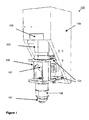
- FIG. 1 is a perspective view from one side of an exemplary microscope lens support assembly complete with voice coil that may be used in conjunction with the present invention
- FIG. 2 is a cross-section through the same exemplary microscope lens support assembly that may be used in conjunction with the present invention
- FIG. 3A shows an exemplary control system for maintaining a static lens position that may be integrated into the control system of the present invention
- FIG. 3B shows an exemplary control system that can be used to implement the present invention
- FIG. 3C shows a variation of the control system of FIG. 3B ;
- FIG. 4 is a flow chart showing an exemplary method according to the present invention.
- FIG. 5 is a perspective view of an exemplary position encoder that may be used to measure lens position
- FIG. 6 is an example of a waveform that may be used to produce a deviation signal.
- FIG. 1 An example of microscope objective lens support assembly for use with the method and system of the present invention is shown in FIG. 1 .
- the objective lens support assembly 100 of FIG. 1 has an objective lens 101 mounted at the bottom of the assembly.
- the objective lens 101 is supported in a barrel 108 and is typically held in position within the barrel 108 by a screw thread.
- the barrel 108 is then also mounted within a main body 102 of the lens assembly using a second screw thread 110 , as may be seen in FIG. 2 .
- the main body 102 is located above the objective microscope lens 101 and contains a mirror 107 .
- the mirror is angled so as to reflect light from the main body 102 into suitably configured receiving apparatus (not shown).
- the main body 102 is mounted between two leaf springs 104 which can flex to allow the main body 102 to substantially move along a linear axis 115 defined by the vertical. This linear axis is visible in FIG. 2 .
- a linear actuator in the form of a voice coil actuator 103 .
- This voice coil actuator is typically a standard “off the shelf” item, in this example manufactured by BEI Technologies Inc.
- the voice coil actuator 103 is mounted directly above the main body 102 so that the centre of gravity of the main body 102 , the lens 101 and the voice coil actuator 103 are collinear. This then places the centre of gravity of all components directly upon the linear axis 115 along which the voice coil actuator provides movement.
- a voice coil actuator adjustment block 106 Above the voice coil actuator 103 is mounted a voice coil actuator adjustment block 106 .
- This adjustment block 106 allows the mechanical and dynamic properties of the voice coil actuator to be tailored to a specific lens assembly.
- the leaf spring 104 and the voice coil adjustment block 106 are both mounted to voice coil 105 .
- This bracket is typically made from a close grained grey cast iron which provides a dense material to dampen any unwanted vibrations and to resist compaction under an upwards or recoil force generated by the voice coil actuator
- FIG. 2 A cross-section of the same assembly 100 is shown in FIG. 2 .
- the thread assembly 110 used to mount the objective lens 101 within barrel 102 can be seen.
- linear axis 115 along which the voice call axis 103 is configured to move.
- leaf springs 104 are mounted to voice coil mounting bracket 105 via a flexural base 111 .
- Mirror 107 is also connected to this same flexural base 111 .
- the voice coil actuator 103 is capable of applying a known force in proportion to the current supplied to the actuator. However, it is not capable of holding a static position. To enable the voice coil actuator 103 to maintain a static position a position encoder is used to measure the position of the objective lens in use so that a positional control feedback loop can be established.
- An example of a suitable position encoder is shown in FIG. 5 .
- Encoder assembly 500 comprises encoder strip 501 , encoder 502 , encoder housing 503 and encoder mounting bracket 504 .
- the housing 503 allows a suitable alignment adjustment to be made to the encoder in order to provide an accurate positional measurement.
- Encoder assembly 500 may be provided by a Renishaw system.
- the controller used to establish the positional control feedback loop to maintain a fixed position of the objective lens is shown in FIG. 3A .
- the feedback loop begins with a reference position 303 , typically provided by the imaging control software. This is used to send a suitable control signal to the drive unit 308 of the voice actuator coil 103 by way of a loop compensation filter 304 and an amplifier 309 .
- the loop compensation filter converts a signal related to a position to a signal suitable for controlling the drive unit.
- the amplifier 309 and the loop compensation filter 304 are standard components of most feedback control loops; the amplifier 309 provides the loop gain so that small errors can produce control signals with enough power to make the corrective movements and the loop compensation filter 304 modifies the loop response to retain stability within the feedback loop.
- the drive unit 308 will cause the voice coil actuator 103 to move along the linear axis 115 which will in turn move the lens and mount, collectively here referred to as item 307 .
- the lens and mount control block 307 represents the effect of the lens 101 , barrel 108 , and main body 102 on the dynamics of the assembly 100 .
- the movement of the lens and mount 307 is recorded by the encoder electronics 306 which form part of the encoder assembly 500 .
- This then enables an actual position 305 of the objective microscope lens to be calculated.
- the actual position 305 is then compared with the reference position 303 in order to adjust the current supplied to the drive unit 308 of voice coil actuator 103 to maintain the objective lens 101 at the required position.
- this comparison is performed by subtracting the actual position 305 from the reference position 303 at comparator 311 and then using the difference of the reference position 303 and the actual position 305 to control the drive unit 308 .
- the control loop shown in FIG. 3A provides accurate control to maintain a correct lens position at low speed, however it is not able to respond fast enough to control the lens position during medium to fast speed movements.
- maintaining a correct lens position at low speed may involve movements of the order of millimeters on a timescale of tens of seconds; whereas rapid or fast movements may involve movements of the order of 1 micrometer on a timescale of around 200 microseconds and medium speed motions may involve movements of the order of tens of micrometers over a period of around a few milliseconds to 1 second.
- the behaviour of the lens and its mount 307 is mainly determined by gravity and by residual forces in the support system for the mount. These residual forces can be calculated by considering the mechanics of the leaf spring or “flexure” mounting support.
- the behaviour of the lens and the lens mount 307 is mainly determined by the dynamics of their mass and any applied force. These dynamics can be well controlled with reasonable accuracy by applying the correct pattern of force in the form of a correct pattern of current for the drive unit 308 of the voice coil actuator 103 .
- This current pattern can be provided in the form of a deviation signal which is characteristic of a predetermined positional deviation from the reference position. Typically the positional deviation varies with time, e.g. a small displacement away from a reference position of the lens that changes with time and eventually returns to the reference position, and thus the deviation signal is a dynamic signal.
- control system of FIG. 3B further comprises a deviation signal source 313 , calculation means 314 to calculate the predicted effect of the deviation signal on the position of the lens, and summation or comparison elements 310 and 312 .
- the deviation signal source 313 outputs a component of the drive signal in the form of a deviation signal, which is eventually used to drive the drive unit 308 .
- This signal component is sent from the deviation signal source 313 to summation element 310 .
- the signal component produced by the deviation signal source 313 is also sent to calculation means 314 , which is adapted to calculate a positional displacement to be used in the control loop.
- This displacement is calculated based on the motion of the lens and lens mount 307 that would be expected if the signal component were to be applied to the drive unit 308 .
- the calculation means 314 uses a look-up table with predicted displacement measurements indexed by particular signal component ranges. Such a table may be pre-calculated in the design stage.
- the calculation means 314 solves electro-mechanical equations in real time to generate the predicted displacement measurements.
- the deviation signal will be correlated with or characteristic of the resultant positional deviation, but the waveform that makes up the deviation signal need not resemble the waveform of the resultant motion.
- the deviation signal may be a voltage signal or a current signal.
- the predicted effect of the deviation calculated by calculation means 314 is subtracted from the signal representative of the actual position 305 of the lens at summation point 312 .
- a modified measurement signal reflective of the subtraction of the predicted effect of the deviation from the actual position 315 is then compared with reference signal 303 at summation point 311 .
- the deviation signal itself is added to the result of this comparison, after the result has passed through the loop compensation filter 304 , at summation point 310 to generate a resultant positional control signal which is passed to the amplifier 309 and is used to drive the drive unit 308 of the voice coil actuator 103 .
- a reference signal 303 is first supplied to hold the lens and lens mount at a stable position; a measurement signal is then received at step 402 representative of the actual position 305 ; if a deviation is to be applied, a deviation signal is applied at step 403 and the eventual positional control signal is then generated at step 404 using the control circuit of FIG. 3B .
- FIG. 3C A variation of the control system of FIG. 3B is shown in FIG. 3C .
- the predicted effect of the deviation i.e. a displacement signal
- Displacement signal source 314 generates a displacement signal that corresponds to the required positional deviation of the lens and lens mount 307 .
- Displacement signal source 314 then sends this displacement signal to deviation signal calculation means 313 , which calculates the deviation signal required for the drive unit 308 to produce the displacement required from the displacement signal, i.e. the predicted deviation required for the displacement.
- the deviation signal calculation means 313 then sends the deviation signal to summation element 310 , wherein it is combined with other drive signal components to produce a drive signal that is used to drive the drive unit 308 .
- the deviation signal may be a voltage or current signal and the calculations performed by the deviation signal calculation means 313 may involve the use of a look-up table or the solution of electro-mechanical equations. A choice is typically made between the control system of FIG. 3B and the control system of FIG. 3C , however, in practice, either can be used to implement the present invention, depending on specific implementation requirements.
- the control system of FIG. 3B or 3 C allows the fast motion to be applied dynamically and the reference or base position to be maintained using the encoder and the feed back features of FIG. 3A after the fast motion has been applied.
- the control system of FIG. 3B or 3 C operates so as to generate the two motions independently.
- a fast movement can be used to find the best focal position without compromising an original optimal best focus position as held by the static position and feedback loop.
- FIG. 6 shows an example of a waveform that may be used to produce such a short range scan.
- the waveform 600 of FIG. 6 comprises a saw-tooth like waveform, wherein the horizontal axis represents time and the vertical axis represents a deviation from a reference position along linear axis 115 .
- the waveform has a fast speed component 603 and a medium speed component 604 : the fast or rapid speed component in one direction may represent a fly-back procedure which is then followed by a more gradual scan motion in an opposite direction. Whist this waveform represents the motion of the lens the deviation signal used to generate such motion may differ in form, for example the deviation signal may resemble the double differential of the waveform.
- the present invention makes it possible to create and control the small, fast movements with an open-loop process relying only on simple force and acceleration calculations and then also allows control of slower, longer movements using a closed-loop process.
- the combination of open and closed loop control for the varying movements enables accurate control of the lens whilst preventing the system drifting slowly away from a set operating point.
- the feedback loop will correct for any errors during the slow motion 604 .
- the predicted positional effect of the deviation 314 is subtracted from the measurement of the lens position 305 provided by the encoder 300 any error in positioning of the lens during the scan portion of the waveform 604 will result in an error signal being produced as a result of the comparison performed by summation point 311 .
- the features of the static motion feedback loop shown in FIG. 3A then operate to reduce this error. This results in a motion of the lens and mount 307 that follows the required deviation.
- the present invention also allows the control of slower motions around a fixed reference position.
- the advantage of the present invention is that it allows a combination of open-loop dynamic control of fast movements limited in space and time yet retains closed-loop feedback control for longer term “static” positioning.
Landscapes
- Physics & Mathematics (AREA)
- Chemical & Material Sciences (AREA)
- Analytical Chemistry (AREA)
- General Physics & Mathematics (AREA)
- Optics & Photonics (AREA)
- Lens Barrels (AREA)
- Microscoopes, Condenser (AREA)
- Automatic Focus Adjustment (AREA)
Abstract
Description
-
- a. receiving a reference signal corresponding to a reference position of the microscope lens;
- b. receiving a measurement signal corresponding to an actual position of the microscope lens;
- c. receiving a deviation signal characteristic of a predetermined positional deviation from the reference position; and
- d. using the measurement signal, the deviation signal and the reference signal to generate a positional control signal for use in setting the position of the microscope lens.
-
- a receiver for receiving a reference signal, a measurement signal, and a deviation signal, the reference signal corresponding to a reference position of the microscope lens, the measurement signal corresponding to an actual position of the microscope lens, and the deviation signal characteristic of a predetermined positional deviation of the microscope lens from a reference position; and
- a controller for generating a positional control signal for use in setting the position of the microscope lens based upon the signals received by the receiver.
Claims (21)
Priority Applications (4)
| Application Number | Priority Date | Filing Date | Title |
|---|---|---|---|
| US12/121,830 US8319829B2 (en) | 2008-05-16 | 2008-05-16 | Method and system for controlling the position of a microscope lens |
| AT09160403T ATE527569T1 (en) | 2008-05-16 | 2009-05-15 | METHOD AND SYSTEM FOR CONTROLLING THE POSITION OF A MICROSCOPE LENS |
| EP09160403A EP2120080B1 (en) | 2008-05-16 | 2009-05-15 | A method and system for controlling the position of a microscope lens |
| JP2009119944A JP5519184B2 (en) | 2008-05-16 | 2009-05-18 | Method and system for controlling the position of a microscope lens |
Applications Claiming Priority (1)
| Application Number | Priority Date | Filing Date | Title |
|---|---|---|---|
| US12/121,830 US8319829B2 (en) | 2008-05-16 | 2008-05-16 | Method and system for controlling the position of a microscope lens |
Publications (2)
| Publication Number | Publication Date |
|---|---|
| US20090284590A1 US20090284590A1 (en) | 2009-11-19 |
| US8319829B2 true US8319829B2 (en) | 2012-11-27 |
Family
ID=40953439
Family Applications (1)
| Application Number | Title | Priority Date | Filing Date |
|---|---|---|---|
| US12/121,830 Active 2031-08-24 US8319829B2 (en) | 2008-05-16 | 2008-05-16 | Method and system for controlling the position of a microscope lens |
Country Status (4)
| Country | Link |
|---|---|
| US (1) | US8319829B2 (en) |
| EP (1) | EP2120080B1 (en) |
| JP (1) | JP5519184B2 (en) |
| AT (1) | ATE527569T1 (en) |
Cited By (1)
| Publication number | Priority date | Publication date | Assignee | Title |
|---|---|---|---|---|
| WO2020244779A1 (en) * | 2019-06-07 | 2020-12-10 | Leica Microsystems Cms Gmbh | A system and method for processing biology-related data, a system and method for controlling a microscope and a microscope |
Families Citing this family (3)
| Publication number | Priority date | Publication date | Assignee | Title |
|---|---|---|---|---|
| GB201620548D0 (en) | 2016-12-02 | 2017-01-18 | Nordson Corp | Bond test apparatus and method |
| EP3428708B1 (en) | 2017-07-10 | 2023-05-17 | FZMB GmbH Forschungszentrum für Medizintechnik und Biotechnologie | Device for moving an optical element along the optical axis of a microscope |
| CN109068066B (en) * | 2018-10-10 | 2020-07-10 | Oppo广东移动通信有限公司 | Camera focusing correction method, related equipment and storage medium |
Citations (13)
| Publication number | Priority date | Publication date | Assignee | Title |
|---|---|---|---|---|
| JPS5946611A (en) | 1982-09-09 | 1984-03-16 | Toshiba Corp | Device for optical inspection |
| US4863252A (en) * | 1988-02-11 | 1989-09-05 | Tracor Northern, Inc. | Objective lens positioning system for confocal tandem scanning reflected light microscope |
| US5009488A (en) * | 1986-02-11 | 1991-04-23 | University Of Massachusetts Medical Center | Filter accessory for an imaging microspectrofluorimeter |
| US5293042A (en) * | 1991-05-10 | 1994-03-08 | Olympus Optical Co., Ltd. | Servo circuit of scanning probe microscope |
| DE19702752A1 (en) | 1997-01-27 | 1998-07-30 | Zeiss Carl Jena Gmbh | Control system for scanner drive esp. for laser scanning microscope |
| US6057547A (en) * | 1992-03-13 | 2000-05-02 | Thermomicorosrescoper, Corp | Scanning probe microscope with scan correction |
| US20030089845A1 (en) | 2001-11-15 | 2003-05-15 | Leica Microsystems Heidelberg Gmbh | Method for operating a positioning apparatus, and scanning microscope |
| EP1389868A2 (en) | 2002-08-12 | 2004-02-18 | Zeiss Optronik GmbH | Scanner and method for operating a scanner |
| US20060007316A1 (en) | 2004-06-28 | 2006-01-12 | Canon Kabushiki Kaisha | Position sensing device |
| EP1617250A1 (en) | 2004-07-16 | 2006-01-18 | CARL ZEISS JENA GmbH | Method for acquisition of at least one region of interest with a light scanning microscope having a linear illumination |
| US20060279739A1 (en) | 2005-06-10 | 2006-12-14 | Tomoaki Yamanaka | Position control apparatus and optical apparatus |
| DE102005047200A1 (en) | 2005-10-01 | 2007-04-05 | Carl Zeiss Jena Gmbh | Optical scanner controller correcting method for sample image scanning device, involves correcting transfer function based on variations of parameters so that deviation of actual position of structure from target position is reduced |
| JP2007147680A (en) | 2005-11-24 | 2007-06-14 | Canon Inc | POSITION CONTROL DEVICE AND OPTICAL DEVICE USING THE SAME |
Family Cites Families (2)
| Publication number | Priority date | Publication date | Assignee | Title |
|---|---|---|---|---|
| JP4555905B2 (en) * | 1998-01-27 | 2010-10-06 | カール ツアイス マイクロイメージング ゲゼルシャフト ミット ベシュレンクテル ハフツング | Direction control system for scanner drive |
| DE102004034954A1 (en) * | 2004-07-16 | 2006-02-02 | Carl Zeiss Jena Gmbh | Method for detecting at least one sample area with a light scanning microscope |
-
2008
- 2008-05-16 US US12/121,830 patent/US8319829B2/en active Active
-
2009
- 2009-05-15 EP EP09160403A patent/EP2120080B1/en active Active
- 2009-05-15 AT AT09160403T patent/ATE527569T1/en not_active IP Right Cessation
- 2009-05-18 JP JP2009119944A patent/JP5519184B2/en active Active
Patent Citations (19)
| Publication number | Priority date | Publication date | Assignee | Title |
|---|---|---|---|---|
| JPS5946611A (en) | 1982-09-09 | 1984-03-16 | Toshiba Corp | Device for optical inspection |
| US5009488A (en) * | 1986-02-11 | 1991-04-23 | University Of Massachusetts Medical Center | Filter accessory for an imaging microspectrofluorimeter |
| US4863252A (en) * | 1988-02-11 | 1989-09-05 | Tracor Northern, Inc. | Objective lens positioning system for confocal tandem scanning reflected light microscope |
| US5293042A (en) * | 1991-05-10 | 1994-03-08 | Olympus Optical Co., Ltd. | Servo circuit of scanning probe microscope |
| US6057547A (en) * | 1992-03-13 | 2000-05-02 | Thermomicorosrescoper, Corp | Scanning probe microscope with scan correction |
| DE19702752A1 (en) | 1997-01-27 | 1998-07-30 | Zeiss Carl Jena Gmbh | Control system for scanner drive esp. for laser scanning microscope |
| US6037583A (en) | 1997-01-27 | 2000-03-14 | Carl Zeiss Jena Gmbh | Control system for a scanner drive |
| US20030089845A1 (en) | 2001-11-15 | 2003-05-15 | Leica Microsystems Heidelberg Gmbh | Method for operating a positioning apparatus, and scanning microscope |
| EP1389868A2 (en) | 2002-08-12 | 2004-02-18 | Zeiss Optronik GmbH | Scanner and method for operating a scanner |
| US20040036938A1 (en) | 2002-08-12 | 2004-02-26 | Josef Wohlfrom | Scanner and method for operating a scanner |
| US20060007316A1 (en) | 2004-06-28 | 2006-01-12 | Canon Kabushiki Kaisha | Position sensing device |
| JP2006010568A (en) | 2004-06-28 | 2006-01-12 | Canon Inc | Position detection device |
| EP1617250A1 (en) | 2004-07-16 | 2006-01-18 | CARL ZEISS JENA GmbH | Method for acquisition of at least one region of interest with a light scanning microscope having a linear illumination |
| US20060011804A1 (en) | 2004-07-16 | 2006-01-19 | Ralf Engelmann | Process for the observation of at least one sample region with a light raster microscope with linear sampling |
| US20060279739A1 (en) | 2005-06-10 | 2006-12-14 | Tomoaki Yamanaka | Position control apparatus and optical apparatus |
| JP2006343651A (en) | 2005-06-10 | 2006-12-21 | Canon Inc | Optical equipment |
| DE102005047200A1 (en) | 2005-10-01 | 2007-04-05 | Carl Zeiss Jena Gmbh | Optical scanner controller correcting method for sample image scanning device, involves correcting transfer function based on variations of parameters so that deviation of actual position of structure from target position is reduced |
| US20090008539A1 (en) | 2005-10-01 | 2009-01-08 | Joerg Steinert | Method for correcting a control of an optical scanner in a device for mapping a sample by scanning and the device for performing the method |
| JP2007147680A (en) | 2005-11-24 | 2007-06-14 | Canon Inc | POSITION CONTROL DEVICE AND OPTICAL DEVICE USING THE SAME |
Non-Patent Citations (1)
| Title |
|---|
| Search Report corresponding to 09160403.3-2217 dated Aug. 31, 2009. |
Cited By (2)
| Publication number | Priority date | Publication date | Assignee | Title |
|---|---|---|---|---|
| WO2020244779A1 (en) * | 2019-06-07 | 2020-12-10 | Leica Microsystems Cms Gmbh | A system and method for processing biology-related data, a system and method for controlling a microscope and a microscope |
| US12026191B2 (en) | 2019-06-07 | 2024-07-02 | Leica Microsystems Cms Gmbh | System and method for processing biology-related data, a system and method for controlling a microscope and a microscope |
Also Published As
| Publication number | Publication date |
|---|---|
| EP2120080B1 (en) | 2011-10-05 |
| EP2120080A1 (en) | 2009-11-18 |
| US20090284590A1 (en) | 2009-11-19 |
| ATE527569T1 (en) | 2011-10-15 |
| JP2009276771A (en) | 2009-11-26 |
| JP5519184B2 (en) | 2014-06-11 |
Similar Documents
| Publication | Publication Date | Title |
|---|---|---|
| CN101713859B (en) | Optical apparatus | |
| US9179048B2 (en) | Camera module | |
| US5467642A (en) | Scanning probe microscope and method of control error correction | |
| US8319829B2 (en) | Method and system for controlling the position of a microscope lens | |
| US7591171B2 (en) | Atomic force microscope | |
| US5847874A (en) | Control apparatus for positional control of an optical system | |
| TW201001086A (en) | Position control apparatus including iterative learning circuit, exposure apparatus, method for manufacturing device, and iterative learning method for use in position control apparatus having iterative learning circuit including learning filter | |
| US5097119A (en) | Device for precisely measuring the distance between a test point on a test surface and a reference plane | |
| Csencsics et al. | Integration of control design and system operation of a high performance piezo-actuated fast steering mirror | |
| NL1037639C2 (en) | Lithography system with lens rotation. | |
| JP6270998B2 (en) | EUV imaging device | |
| CN108369386B (en) | Device for adjusting assembly | |
| US11415895B2 (en) | Compensation of creep effects in an imaging device | |
| IL272694B1 (en) | Position adjustment in an electronic beam-based test facility | |
| US20210405358A1 (en) | Compensation of creep effects in an imaging device | |
| US20140078487A1 (en) | Method for moving an optical element of a projection exposure apparatus for microlithography | |
| US11703770B2 (en) | Compensation of creep effects in an imaging device | |
| US4393309A (en) | Method and apparatus for controlling the objective lens in a scanning electron microscope or the like | |
| JP2019505828A (en) | Optical imaging device with actively adjustable metrology support unit | |
| US7315412B2 (en) | Focus stabilizing mechanism for microscopes and similar optical instruments | |
| EP0346479A1 (en) | Optical head | |
| US6287735B2 (en) | Method and apparatus for controlling the leveling table of a wafer stage | |
| EP1361486B1 (en) | Moving member mechanism and control method therefor | |
| US8243262B2 (en) | Method and system for supporting a moving optical component on a sloped portion | |
| JP2006308709A (en) | Microscope stage, focal position measurement device and confocal microscope system |
Legal Events
| Date | Code | Title | Description |
|---|---|---|---|
| AS | Assignment |
Owner name: FFEI LIMITED, UNITED KINGDOM Free format text: ASSIGNMENT OF ASSIGNORS INTEREST;ASSIGNORS:HAWES, WILLIAM ROLAND;BROMLEY, NIGEL INGRAM;REEL/FRAME:020956/0808 Effective date: 20080508 |
|
| AS | Assignment |
Owner name: FFEI LIMITED, UNITED KINGDOM Free format text: CORRECTIVE ASSIGNMENT TO CORRECT THE ASSIGNEE'S ADDRESS WHICH WAS CHANGED AFTER FILING THE ASSIGNMENT PREVIOUSLY RECORDED ON REEL 020956 FRAME 0808. ASSIGNOR(S) HEREBY CONFIRMS THE ASSIGNMENT;ASSIGNORS:HAWES, WILLIAM ROLAND;BROMLEY, NIGEL INGRAM;REEL/FRAME:025572/0726 Effective date: 20080508 |
|
| FEPP | Fee payment procedure |
Free format text: PAYOR NUMBER ASSIGNED (ORIGINAL EVENT CODE: ASPN); ENTITY STATUS OF PATENT OWNER: LARGE ENTITY |
|
| STCF | Information on status: patent grant |
Free format text: PATENTED CASE |
|
| FPAY | Fee payment |
Year of fee payment: 4 |
|
| MAFP | Maintenance fee payment |
Free format text: PAYMENT OF MAINTENANCE FEE, 8TH YEAR, LARGE ENTITY (ORIGINAL EVENT CODE: M1552); ENTITY STATUS OF PATENT OWNER: LARGE ENTITY Year of fee payment: 8 |
|
| MAFP | Maintenance fee payment |
Free format text: PAYMENT OF MAINTENANCE FEE, 12TH YEAR, LARGE ENTITY (ORIGINAL EVENT CODE: M1553); ENTITY STATUS OF PATENT OWNER: LARGE ENTITY Year of fee payment: 12 |
|
| AS | Assignment |
Owner name: VENTANA MEDICAL SYSTEMS, INC., ARIZONA Free format text: ASSIGNMENT OF ASSIGNORS INTEREST;ASSIGNOR:FFEI LIMITED;REEL/FRAME:068784/0324 Effective date: 20230625 |