EP3428636A1 - Probeneinführungsvorrichtung für gaschromatographen - Google Patents
Probeneinführungsvorrichtung für gaschromatographen Download PDFInfo
- Publication number
- EP3428636A1 EP3428636A1 EP16893399.2A EP16893399A EP3428636A1 EP 3428636 A1 EP3428636 A1 EP 3428636A1 EP 16893399 A EP16893399 A EP 16893399A EP 3428636 A1 EP3428636 A1 EP 3428636A1
- Authority
- EP
- European Patent Office
- Prior art keywords
- sample
- container
- flow channel
- gas chromatograph
- port
- Prior art date
- Legal status (The legal status is an assumption and is not a legal conclusion. Google has not performed a legal analysis and makes no representation as to the accuracy of the status listed.)
- Withdrawn
Links
- 238000010438 heat treatment Methods 0.000 claims abstract description 37
- 239000007789 gas Substances 0.000 claims description 110
- 239000012159 carrier gas Substances 0.000 claims description 46
- 239000012141 concentrate Substances 0.000 claims description 10
- 238000010586 diagram Methods 0.000 description 16
- 239000011261 inert gas Substances 0.000 description 10
- IJGRMHOSHXDMSA-UHFFFAOYSA-N Atomic nitrogen Chemical compound N#N IJGRMHOSHXDMSA-UHFFFAOYSA-N 0.000 description 8
- 229910001873 dinitrogen Inorganic materials 0.000 description 8
- 239000001307 helium Substances 0.000 description 8
- 229910052734 helium Inorganic materials 0.000 description 8
- SWQJXJOGLNCZEY-UHFFFAOYSA-N helium atom Chemical compound [He] SWQJXJOGLNCZEY-UHFFFAOYSA-N 0.000 description 8
- VYPSYNLAJGMNEJ-UHFFFAOYSA-N silicon dioxide Inorganic materials O=[Si]=O VYPSYNLAJGMNEJ-UHFFFAOYSA-N 0.000 description 8
- 238000003795 desorption Methods 0.000 description 5
- 238000004140 cleaning Methods 0.000 description 4
- 239000011347 resin Substances 0.000 description 3
- 229920005989 resin Polymers 0.000 description 3
- 239000000377 silicon dioxide Substances 0.000 description 3
- 230000032258 transport Effects 0.000 description 3
- 230000008016 vaporization Effects 0.000 description 3
- 210000002268 wool Anatomy 0.000 description 3
- 239000000853 adhesive Substances 0.000 description 2
- 230000001070 adhesive effect Effects 0.000 description 2
- 239000003463 adsorbent Substances 0.000 description 2
- 230000001678 irradiating effect Effects 0.000 description 2
- 239000007788 liquid Substances 0.000 description 2
- 230000000149 penetrating effect Effects 0.000 description 2
- 239000010453 quartz Substances 0.000 description 2
- 239000007787 solid Substances 0.000 description 2
- 238000009834 vaporization Methods 0.000 description 2
- 230000000903 blocking effect Effects 0.000 description 1
- 238000007796 conventional method Methods 0.000 description 1
- 230000000694 effects Effects 0.000 description 1
- 238000002347 injection Methods 0.000 description 1
- 239000007924 injection Substances 0.000 description 1
- 239000000463 material Substances 0.000 description 1
- 238000000034 method Methods 0.000 description 1
- 230000004048 modification Effects 0.000 description 1
- 238000012986 modification Methods 0.000 description 1
- 238000007789 sealing Methods 0.000 description 1
- 238000011144 upstream manufacturing Methods 0.000 description 1
Images


Classifications
-
- G—PHYSICS
- G01—MEASURING; TESTING
- G01N—INVESTIGATING OR ANALYSING MATERIALS BY DETERMINING THEIR CHEMICAL OR PHYSICAL PROPERTIES
- G01N30/00—Investigating or analysing materials by separation into components using adsorption, absorption or similar phenomena or using ion-exchange, e.g. chromatography or field flow fractionation
- G01N30/02—Column chromatography
- G01N30/04—Preparation or injection of sample to be analysed
- G01N30/16—Injection
- G01N30/20—Injection using a sampling valve
-
- G—PHYSICS
- G01—MEASURING; TESTING
- G01N—INVESTIGATING OR ANALYSING MATERIALS BY DETERMINING THEIR CHEMICAL OR PHYSICAL PROPERTIES
- G01N30/00—Investigating or analysing materials by separation into components using adsorption, absorption or similar phenomena or using ion-exchange, e.g. chromatography or field flow fractionation
- G01N30/02—Column chromatography
- G01N30/04—Preparation or injection of sample to be analysed
- G01N30/06—Preparation
- G01N30/12—Preparation by evaporation
-
- G—PHYSICS
- G01—MEASURING; TESTING
- G01N—INVESTIGATING OR ANALYSING MATERIALS BY DETERMINING THEIR CHEMICAL OR PHYSICAL PROPERTIES
- G01N30/00—Investigating or analysing materials by separation into components using adsorption, absorption or similar phenomena or using ion-exchange, e.g. chromatography or field flow fractionation
- G01N30/02—Column chromatography
- G01N30/04—Preparation or injection of sample to be analysed
- G01N30/16—Injection
- G01N30/18—Injection using a septum or microsyringe
-
- G—PHYSICS
- G01—MEASURING; TESTING
- G01N—INVESTIGATING OR ANALYSING MATERIALS BY DETERMINING THEIR CHEMICAL OR PHYSICAL PROPERTIES
- G01N30/00—Investigating or analysing materials by separation into components using adsorption, absorption or similar phenomena or using ion-exchange, e.g. chromatography or field flow fractionation
- G01N30/02—Column chromatography
- G01N2030/022—Column chromatography characterised by the kind of separation mechanism
- G01N2030/025—Gas chromatography
Definitions
- the present invention relates to a sample introduction device for a gas chromatograph which guides a vaporized sample to a gas chromatograph.
- a sample introduction device for introducing a sample into a gas chromatograph
- a sample introduction device adopting a thermal desorption system is known (for example, see Patent Document 1 below).
- Patent Document 1 a sample introduction device adopting a thermal desorption system
- the sample components are once trapped in a trap column. Then, by heating the sample components in the trap column, the sample components are desorbed.
- the sample components can be introduced into a gas chromatograph.
- a chamber In the case of trapping a sample in the sample tube, for example, a chamber is used. Specifically, by heating the inside of the chamber and vaporizing the sample in a state where the sample is contained in the chamber, the vaporized sample is trapped in the sample tube. By setting the sample tube in which the sample is trapped in this manner in the sample introduction device adopting the thermal desorption system, the sample in the sample tube is desorbed and is introduced into the gas chromatograph.
- the sample When the sample is vaporized in the chamber, if the sample is irradiated with ultraviolet rays, the sample may be changed in quality. That is, by heating the sample while irradiating the sample with ultraviolet rays, it is possible to trap a gas generated at a time when the sample is changed in quality in the sample tube and to analyze the gas.
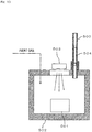
- FIG. 10 is a schematic cross-sectional view for explaining an aspect for trapping a sample in a sample tube 500.
- a sample 501 is contained in a chamber 502 and is heated.
- An ultraviolet lamp 503 emits ultraviolet rays into the chamber 502.
- an inert gas such as a nitrogen gas or a helium gas is supplied into the chamber 502.
- the sample tube 500 is detachable from the chamber 502.
- the sample 501 is heated while being irradiated with ultraviolet rays from the ultraviolet lamp 503 in a state where the sample tube 500 is attached to the chamber 502.
- the sample 501 is vaporized and gas is generated.
- the inert gas is supplied into the chamber 502, and therefore the vaporized sample is introduced into the sample tube 500 together with the inert gas.
- An adsorbent 504 is provided in the sample tube 500.
- the vaporized sample is adsorbed and trapped by the adsorbent while passing through the sample tube 500. After the sample is trapped in the sample tube 500 in this manner, the sample tube 500 is detached from the chamber 502 and set in a sample introduction device adopting a thermal desorption system.
- Patent Document 1 JP 5648608 B1
- the present invention has been made in view of the above circumstances, and an object of the present invention is to provide a sample introduction device for a gas chromatograph capable of simplifying an operation for analyzing a sample.
- the operation of setting the sample tube in the sample introduction device is unnecessary, and the operation of cleaning the chamber is also unnecessary. Therefore, it is possible to simplify an operation for analyzing a sample.
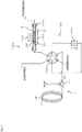
- FIG. 1 is a flow channel diagram illustrating a configuration example of a sample introduction device 100 according to a first embodiment of the present invention.
- the sample introduction device 100 is a sample introduction device for a gas chromatograph configured to introduce a sample into a gas chromatograph 1.
- a container 2 in which a sample is enclosed is set, and the sample (sample gas) vaporized in the container 2 is introduced into the gas chromatograph 1.
- the gas chromatograph 1 is a concept which includes a gas chromatograph mass spectrometer.
- the sample introduction device 100 includes a container holding part 101, a heating unit 102, an ultraviolet irradiation unit 103, a trap part 104, a flow channel switching part 105, and the like.
- the container holding part 101 and the trap part 104 are connected to the flow channel switching part 105 through pipes.
- the container 2 is a transparent or translucent tubular elongated member made of quartz, for example.
- the container 2 is attached to the container holding part 101, and thus constitutes part of the pipe communicating with the flow channel switching part 105.
- the container holding part 101 includes a seal member (not illustrated) such as an O-ring. The seal member can prevent gas from leaking from the space between the container holding part 101 and the container 2.
- a sample 22 is held in a state of being sandwiched between a pair of pieces of silica wool 21.
- the sample 22 is a solid sample such as a resin; however, the sample 22 is not limited to this, and may be a liquid such as an adhesive.
- a carrier gas is supplied into the container 2 through a pipe, and the carrier gas which has passed through a space between the pair of pieces of silica wool 21 is sent to the flow channel switching part 105.
- the carrier gas may be an inert gas such as a nitrogen gas or a helium gas, or may be an active gas.
- the heating unit 102 is provided near the container holding part 101 and vaporizes the sample 22 by heating externally the container 2 attached to the container holding part 101.
- the ultraviolet irradiation unit 103 is provided near the container holding part 101 and emits ultraviolet rays toward the container 2 attached to the container holding part 101.
- the ultraviolet rays pass through the container 2, and the sample 22 is irradiated with the ultraviolet rays.
- a sample gas generated by vaporization of the sample 22 in the container 2 is sent to the flow channel switching part 105 together with the carrier gas supplied into the container 2.
- the trap part 104 is constituted of, for example, a trap column, and traps and concentrates the sample (sample gas) vaporized in the container 2. By heating the trap part 104 in which the sample is concentrated, the sample in the trap part 104 is volatilized and desorbed, and the carrier gas transports the sample to the gas chromatograph 1.
- the container holding part 101, the trap part 104, the flow channel switching part 105, the pipes connecting them, and the like constitute a sample supply part 106 that supplies the sample vaporized in the container 2 to a gas chromatograph 1 side.
- the flow channel switching part 105 is constituted of, for example, a six-way valve having six ports a to f.
- the port a of the flow channel switching part 105 communicates with the container holding part 101. Both end portions of the trap part 104 communicate with the port b and the port e of the flow channel switching part 105.
- the port c of the flow channel switching part 105 communicates with the gas chromatograph 1.
- a carrier gas is supplied to the port d of the flow channel switching part 105.
- the carrier gas is an inert gas such as a nitrogen gas or a helium gas.
- the port f of the flow channel switching part 105 communicates with a discharge port.
- the port a and the port b of the flow channel switching part 105 communicate with each other, and the port e and the port f of the flow channel switching part 105 communicate with each other. Therefore, the carrier gas supplied from one-end side (upstream side) to the container 2 passes through the container 2 and then flows into the trap part 104 through the flow channel switching part 105. As a result, the sample vaporized in the container 2 flows out from the other-end side (downstream side) of the container 2, is supplied to the gas chromatograph 1 side, and is trapped in the trap part 104. The carrier gas obtained after the sample is trapped by the trap part 104 is discharged from the discharge port through the flow channel switching part 105.
- the port c and the port d of the flow channel switching part 105 communicate with each other. Therefore, the carrier gas supplied to the port d of the flow channel switching part 105 is guided from the port c to the gas chromatograph 1 without passing through the trap part 104.
- the flow channel switching part 105 is switched after the sample is trapped in the trap part 104 in the above state, the sample is introduced from the trap part 104 to the gas chromatograph 1.
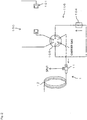
- FIG. 2 is a flow channel diagram illustrating a state where the flow channel switching part 105 is switched from the state illustrated in FIG. 1 .
- the port b and the port c of the flow channel switching part 105 communicate with each other, and the port d and the port e of the flow channel switching part 105 communicate with each other. Therefore, the carrier gas supplied to the port d of the flow channel switching part 105 flows from the port e into the trap part 104. At this time, the trap part 104 is heated. As a result, the sample concentrated in the trap part 104 is desorbed and is supplied to the gas chromatograph 1 side through the port b and the port c of the flow channel switching part 105.
- the port a and the port f of the flow channel switching part 105 communicate with each other.
- the container holding part 101 does not communicate with the trap part 104. Therefore, as illustrated in FIG. 2 , the container 2 may be detached from the container holding part 101.
- the gas chromatograph 1 includes a sample introduction part 11, a column 12, and the like.
- the sample supplied from the trap part 104 to the gas chromatograph 1 together with the carrier gas is introduced into the column 12 from the sample introduction part 11 and is separated into respective sample components while passing through the column 12.
- the respective sample components separated in this manner are detected by a detector (not illustrated), and a chromatogram is obtained as an analysis result.
- part of the sample supplied from the trap part 104 to the sample introduction part 11 is discharged to the outside together with the carrier gas.
- the sample is introduced into the column 12 using a so-called a split injection method.
- the present invention is not limited to such a configuration, and a configuration in which entirety of the sample supplied from the trap part 104 to the sample introduction part 11 is introduced into the column 12 may be adopted.
- the sample 22 in the container 2 is irradiated with ultraviolet rays from the ultraviolet irradiation unit 103, and the sample 22 in the container 2 is heated and vaporized by the heating unit 102. Therefore, the vaporized sample (sample gas) can be directly supplied from the container 2 to the gas chromatograph 1 side. Therefore, unlike the configuration in which a sample is trapped in a sample tube by using a chamber, the operation of setting the sample tube in a sample introduction device is unnecessary, and the operation of cleaning the chamber is also unnecessary. Therefore, the operation for analyzing a sample can be simplified.
- the container 2 formed of a tubular member is provided in the flow channel for supplying the carrier gas, and the carrier gas supplied into the container 2 enables the vaporized sample to be supplied from the container 2 to the gas chromatograph 1 side. Therefore, it is possible to introduce the sample into the gas chromatograph 1 by using a configuration similar to the configuration of a sample introduction device adopting a thermal desorption system.
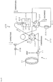
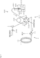
- FIG. 3 is a flow channel diagram illustrating a configuration example of a sample introduction device 200 according to a second embodiment of the present invention.
- the sample introduction device 200 is a sample introduction device for a gas chromatograph configured to introduce a sample into a gas chromatograph 1.
- a container 3 in which a sample is enclosed is set, and the sample (sample gas) vaporized in the container 3 is introduced into the gas chromatograph 1.
- sample gas sample gas
- the sample introduction device 200 includes a needle 201, a heating unit 202, an ultraviolet irradiation unit 203, a trap part 205, a first flow channel switching part 206, a second flow channel switching part 207, and the like.
- the container 3 includes a transparent or translucent vial 31 made of, for example, quartz, and a resin septum 32 for closing an opening formed at an end portion of the vial 31.
- the sample is enclosed in the vial 31.
- the sample is a solid sample such as a resin; however, the sample is not limited to this, and may be a liquid such as an adhesive.
- One end portion of the needle 201 penetrates the septum 32 and is inserted into the vial 31, and the other end portion of the needle 201 is connected to the first flow channel switching part 206 through a pipe.
- the heating unit 202 is constituted of, for example, an oven in which a heating chamber is formed.
- the inside of the heating unit 202 is kept at a set temperature by a heater (not illustrated).
- the container 3 is housed inside the heating unit 202. As a result, the container 3 is heated externally, and the sample in the container 3 is vaporized. The vaporized sample is stored in an upper space (headspace) in the container 3.
- the ultraviolet irradiation unit 203 is attached to the heating unit 202 and emits ultraviolet rays toward the container 3 housed inside the heating unit 202. Thus, the ultraviolet rays pass through the container 3, and the sample is irradiated with the ultraviolet rays.
- a sample gas generated by vaporization of the sample in the container 3 flows out from the needle 201 inserted into the vial 31, and is sent to the first flow channel switching part 206.
- the trap part 205 is constituted of, for example, a trap column, and traps and concentrates the sample (sample gas) sent from the container 3. By heating the trap part 205 in which the sample is concentrated, the sample in the trap part 205 is volatilized and desorbed, and the carrier gas transports the sample to the gas chromatograph 1.
- the needle 201, the trap part 205, the first flow channel switching part 206, the second flow channel switching part 207, pipes connecting them, and the like constitute a sample supply part 210 that supplies the sample vaporized in the container 3 to a gas chromatograph 1 side.
- Each of the first flow channel switching part 206 and the second flow channel switching part 207 is constituted of, for example, a six-way valve having six ports a to f.
- the port a of the first flow channel switching part 206 communicates with the needle 201.
- the port b of the first flow channel switching part 206 communicates with the port f of the second flow channel switching part 207.
- the port c of the first flow channel switching part 206 communicates with the gas chromatograph 1.
- a carrier gas is supplied to the port d of the first flow channel switching part 206.
- the carrier gas is an inert gas such as a nitrogen gas or a helium gas.
- the port e of the first flow channel switching part 206 communicates with the port e of the second flow channel switching part 207.
- a carrier gas can be supplied to the port f of the first flow channel switching part 206 through a pipe.
- the port f communicates with a discharge port through a branch passage branched from the pipe.
- the carrier gas may be an inert gas such as a nitrogen gas or a helium gas, or may be an active gas.
- a valve 208 is provided in the branch passage, and the valve 208 is closed in the state illustrated in FIG. 3 .
- Both end portions of the trap part 205 communicate with the port a and the port d of the second flow channel switching part 207.
- a carrier gas is supplied to the port b of the second flow channel switching part 207.
- the carrier gas may be an inert gas such as a nitrogen gas or a helium gas, or may be an active gas.
- the port c of the second flow channel switching part 207 communicates with a discharge port.
- the port a and the port b of the first flow channel switching part 206 communicate with each other, and the port e and the port f of the first flow channel switching part 206 communicate with each other.
- the port e and the port f of the second flow channel switching part 207 communicate with each other. Therefore, the carrier gas supplied to the port f of the first flow channel switching part 206 is sent to the needle 201.
- the carrier gas is supplied into the container 3 from the needle 201. Therefore, the inside of the container 3 is pressurized.
- the port c and the port d of the first flow channel switching part 206 communicate with each other, and the carrier gas supplied to the port d is guided from the port c to the gas chromatograph 1.
- the port a and the port b of the second flow channel switching part 207 communicate with each other, and the port c and the port d of the second flow channel switching part 207 communicate with each other. Therefore, the carrier gas supplied to the port b of the second flow channel switching part 207 passes through the trap part 205 and is discharged from the discharge port.
- the second flow channel switching part 207 is switched after the inside of the container 3 is pressurized while the sample in the container 3 is vaporized in the above state, the sample vaporized in the container 3 is guided to the trap part 205.
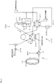
- FIG. 4 is a flow channel diagram illustrating a state where the second flow channel switching part 207 is switched from the state illustrated in FIG. 3 .
- the port a and the port f of the second flow channel switching part 207 communicate with each other, and the port d and the port e of the second flow channel switching part 207 communicate with each other.
- the first flow channel switching part 206 remains in the state illustrated in FIG. 3 .
- supply of the carrier gas to the port f of the first flow channel switching part 206 is stopped, and the valve 208 is opened. Therefore, the sample vaporized in the container 3 is supplied from the needle 201 to the gas chromatograph 1 side by pressure inside the container 3, and is trapped by the trap part 205.
- the carrier gas obtained after the sample is trapped is discharged from the port f of the first flow channel switching part 206 to the discharge port.
- the port b and the port c of the second flow channel switching part 207 communicate with each other. Therefore, the carrier gas supplied to the port b of the second flow channel switching part 207 is discharged from the port c to the discharge port.
- the sample is introduced from the trap part 205 to the gas chromatograph 1.
- FIG. 5 is a flow channel diagram illustrating a state where the first flow channel switching part 206 is switched from the state illustrated in FIG. 4 .
- the port b and the port c of the first flow channel switching part 206 communicate with each other, and the port d and the port e of the first flow channel switching part 206 communicate with each other. Therefore, the carrier gas supplied to the port d of the first flow channel switching part 206 flows into the trap part 205 through the first flow channel switching part 206 and the second flow channel switching part 207. At this time, the trap part 205 is heated.
- the sample concentrated in the trap part 205 is desorbed and is supplied to the gas chromatograph 1 side through the port a and the port f of the second flow channel switching part 207 and the port b and the port c of the first flow channel switching part 206.
- the port a and the port f of the first flow channel switching part 206 communicate with each other.
- the needle 201 may be removed from the container 3 as illustrated in FIG. 5 .
- the sample in the container 3 is irradiated with ultraviolet rays from the ultraviolet irradiation unit 203, and the sample in the container 3 is heated and vaporized by the heating unit 202. Therefore, the vaporized sample (sample gas) can be directly supplied from the container 3 to the gas chromatograph 1 side. Therefore, unlike the configuration in which a sample is trapped in a sample tube by using a chamber, the operation of setting the sample tube in a sample introduction device is unnecessary, and the operation of cleaning the chamber is also unnecessary. Therefore, the operation for analyzing a sample can be simplified.
- the sample vaporized inside the vial 31 is supplied to the gas chromatograph 1 side through the needle 201 penetrating the septum 32 and inserted into the vial 31. Therefore, it is possible to introduce the sample into the gas chromatograph 1 by using a configuration similar to the configuration of a sample introduction device adopting a headspace system.
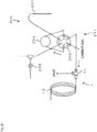
- FIG. 6 is a flow channel diagram illustrating a configuration example of a sample introduction device 300 according to a third embodiment of the present invention.
- the sample introduction device 300 is a sample introduction device for a gas chromatograph configured to introduce a sample into a gas chromatograph 1.
- a container 3 in which a sample is enclosed is set, and the sample (sample gas) vaporized in the container 3 is introduced into the gas chromatograph 1. Note that since the configurations of the gas chromatograph 1 and the container 3 are similar to those of the second embodiment, identical reference signs are given to the drawings, and a detailed description thereof will be omitted.
- the sample introduction device 300 includes a needle 201, a heating unit 202, an ultraviolet irradiation unit 203, a sample loop 204, a flow channel switching part 209, and the like. Since the configurations of the needle 201, the heating unit 202, and the ultraviolet irradiation unit 203 are similar to those of the first embodiment, detailed descriptions of them will be omitted.
- the sample loop 204 functions as a buffer for temporarily storing a sample (sample gas) flowing out from inside the container 3 through the needle 201.
- a carrier gas transports the sample gas stored in the sample loop 204 to a gas chromatograph 1 side.
- the needle 201, the sample loop 204, the flow channel switching part 209, pipes connecting them, and the like constitute a sample supply part 211 that supplies the sample vaporized in the container 3 to the gas chromatograph 1 side.
- the flow channel switching part 209 is constituted of, for example, a six-way valve having six ports a to f.
- the port a of the flow channel switching part 209 communicates with the needle 201.
- Both end portions of the sample loop 204 communicate with the port b and the port e of the flow channel switching part 209.
- the port c of the flow channel switching part 209 communicates with the gas chromatograph 1.
- a carrier gas is supplied to the port d of the flow channel switching part 209.
- the carrier gas is an inert gas such as a nitrogen gas or a helium gas.
- a carrier gas can be supplied to the port f of the flow channel switching part 209 through a pipe.
- the port f communicates with a discharge port through a branch passage branched from the pipe.
- the carrier gas may be an inert gas such as a nitrogen gas or a helium gas, or may be an active gas.
- a valve 208 is provided in the branch passage as in the second embodiment. In the state illustrated FIG. 6 , the valve 208 is closed.
- the port a and the port b of the flow channel switching part 209 communicate with each other, and the port e and the port f of the flow channel switching part 209 communicate with each other. Therefore, the carrier gas supplied to the port f of the flow channel switching part 209 passes through the sample loop 204 and is sent to the needle 201. As illustrated in FIG. 6 , if a tip portion of the needle 201 is inserted into the container 3, the carrier gas is supplied into the container 3 from the needle 201. Therefore, the inside of the container 3 is pressurized.
- the port c and the port d of the flow channel switching part 209 communicate with each other. Therefore, the carrier gas supplied to the port d of the flow channel switching part 209 is guided from the port c to the gas chromatograph 1.
- the valve 208 is opened after the inside of the container 3 is pressurized while the sample in the container 3 is vaporized in this state, the sample vaporized in the container 3 is guided to the sample loop 204.
- FIG. 7 is a flow channel diagram illustrating a state where supply of the carrier gas to the port f of the flow channel switching part 209 is stopped and the valve 208 is opened from the state illustrated in FIG. 6 .
- the sample vaporized in the container 3 is supplied from the needle 201 to the gas chromatograph 1 side by pressure inside the container 3, and the sample loop 204 is filled with the sample.
- the sample overflowing from the sample loop 204 is discharged from the port f of the flow channel switching part 209 to the discharge port.
- the flow channel switching part 209 When the flow channel switching part 209 is switched after the sample is stored in the sample loop 204 in the above state, the sample is introduced from the sample loop 204 to the gas chromatograph 1.
- FIG. 8 is a flow channel diagram illustrating a state where the flow channel switching part 209 is switched from the state illustrated in FIG. 7 .
- the port b and the port c of the flow channel switching part 209 communicate with each other, and the port d and the port e of the flow channel switching part 209 communicate with each other. Therefore, the carrier gas supplied to the port d of the flow channel switching part 209 flows into the sample loop 204 through the port e.
- the sample in the sample loop 204 is supplied to the gas chromatograph 1 side through the port b and the port c of the flow channel switching part 209.
- the port a and the port f of the flow channel switching part 209 communicate with each other.
- the needle 201 since the needle 201 is not communicated with the sample loop 204, the needle 201 may be removed from the container 3 as illustrated in FIG. 8 .
- a sample introduction device for a gas chromatograph may not include the trap part 205 as in the second embodiment.
- the trap part 104 may be omitted.
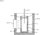
- FIG. 9 is a schematic cross-sectional view illustrating an example of the specific configuration in the heating unit 202.
- the ultraviolet irradiation unit 203 is attached to the heating unit 202.
- a container holding part 4 for holding the container 3 is provided in the heating unit 202.
- the container holding part 4 is made of, for example, a cylindrical member, and can hold the container 3 while housing the container 3 therein.
- a slit 41 is formed in the container holding part 4 so as to penetrate a wall surface of the container holding part 4.
- the slit 41 is formed in the container holding part 4 at a location facing the ultraviolet irradiation unit 203. As a result, ultraviolet rays emitted from the ultraviolet irradiation unit 203 pass through the slit 41 and are guided to the container 3.
- the container 3 can be stably held by the container holding part 4, and the slit 41 formed in the container holding part 4 can limit the area through which ultraviolet rays pass in the container 3. Therefore, since the sample in the container 3 can be efficiently irradiated with ultraviolet rays, it is possible to perform an analysis more satisfactorily.
- the container holding part 4 covers the periphery of the septum 32. That is, the wall surface of the container holding part 4 is positioned between the ultraviolet irradiation unit 203 and the septum 32. Part of the wall surface of the container holding part 4 located between the ultraviolet irradiation unit 203 and the septum 32 constitutes a mask part 42 for blocking ultraviolet rays from the ultraviolet irradiation unit 203 toward an end portion of the container 3. Therefore, since the end portion of the container 3 is not irradiated with ultraviolet rays, change in quality of the septum 32 provided at the end portion of the container 3 can be prevented.
- the configuration of the container holding part 4 is not limited to the above-described configuration.
- the above configuration in which the slit 41 and the mask part 42 are provided can also be applied to the first embodiment.
- the mask part blocks ultraviolet rays from the ultraviolet irradiation unit 103 toward an end portion of the container 2, it is possible to prevent change in quality of the sealing member such as the O-ring provided in the container holding part 101.
- each of the containers 2, 3 is not limited to one.
- a plurality of containers 2 or 3 may be provided.
- the configurations of the containers 2, 3 are not limited to the configurations as in the above embodiments.
- the container to which the present invention is applied may have any other shape or may be formed of any other material as long as a sample can be enclosed in the container, the sample in the container can be heated externally, and the sample inside the container can be irradiated with ultraviolet rays from outside.
- configurations have been described in which a sample is vaporized by heating the sample while irradiating the sample with ultraviolet rays.
- the present invention is not limited to the above configurations.
- a configuration may be adopted in which after a sample is irradiated with ultraviolet rays, irradiation of the ultraviolet rays is stopped, and then the sample is heated to be vaporized.
Landscapes
- Physics & Mathematics (AREA)
- Health & Medical Sciences (AREA)
- Life Sciences & Earth Sciences (AREA)
- Chemical & Material Sciences (AREA)
- Analytical Chemistry (AREA)
- Biochemistry (AREA)
- General Health & Medical Sciences (AREA)
- General Physics & Mathematics (AREA)
- Immunology (AREA)
- Pathology (AREA)
- Sampling And Sample Adjustment (AREA)
Applications Claiming Priority (1)
| Application Number | Priority Date | Filing Date | Title |
|---|---|---|---|
| PCT/JP2016/056946 WO2017154067A1 (ja) | 2016-03-07 | 2016-03-07 | ガスクロマトグラフ用試料導入装置 |
Publications (2)
| Publication Number | Publication Date |
|---|---|
| EP3428636A1 true EP3428636A1 (de) | 2019-01-16 |
| EP3428636A4 EP3428636A4 (de) | 2019-10-30 |
Family
ID=59789078
Family Applications (1)
| Application Number | Title | Priority Date | Filing Date |
|---|---|---|---|
| EP16893399.2A Withdrawn EP3428636A4 (de) | 2016-03-07 | 2016-03-07 | Probeneinführungsvorrichtung für gaschromatographen |
Country Status (4)
| Country | Link |
|---|---|
| US (1) | US10955389B2 (de) |
| EP (1) | EP3428636A4 (de) |
| JP (1) | JP6566116B2 (de) |
| WO (1) | WO2017154067A1 (de) |
Families Citing this family (3)
| Publication number | Priority date | Publication date | Assignee | Title |
|---|---|---|---|---|
| CN110392828B (zh) * | 2018-02-22 | 2022-03-18 | 株式会社岛津制作所 | 试样导入装置 |
| JP7137188B2 (ja) * | 2018-06-12 | 2022-09-14 | 東海電子株式会社 | ガスクロマトグラフ |
| US12571781B2 (en) * | 2023-04-22 | 2026-03-10 | Korea Research Institute Of Standards And Science | Verification method and system for a sample introduction device dedicated to gas chromatography for precisely measuring a concentration of atmospheric greenhouse gas contained in a tedlar bag |
Family Cites Families (14)
| Publication number | Priority date | Publication date | Assignee | Title |
|---|---|---|---|---|
| JPH05172744A (ja) * | 1991-12-26 | 1993-07-09 | Yokogawa Electric Corp | 紫外線吸収検出器 |
| JP2006526154A (ja) * | 2003-05-23 | 2006-11-16 | パーキンエルマー・エルエーエス・インコーポレーテッド | 熱脱離用サンプリングチューブの完全性を検証するための方法 |
| TW200813430A (en) * | 2006-08-01 | 2008-03-16 | Brooks Rand Llc | Automated system for detection of chemical compounds |
| JP4660799B2 (ja) * | 2007-10-04 | 2011-03-30 | フロンティア・ラボ株式会社 | 高分子試料分析装置 |
| US8075842B1 (en) * | 2008-02-27 | 2011-12-13 | EST Analytical, Inc. | Analytical chemical sampling system with sparge vessel |
| US8092744B1 (en) * | 2008-02-27 | 2012-01-10 | EST Analytical, Inc. | Analytical chemical sampling system with bypass mode |
| JP5146264B2 (ja) * | 2008-11-04 | 2013-02-20 | 株式会社島津製作所 | 気体試料導入装置及びそれを備えたガスクロマトグラフ装置 |
| JP5648608B2 (ja) * | 2011-09-06 | 2015-01-07 | 株式会社島津製作所 | 試料導入装置 |
| JP2014035275A (ja) * | 2012-08-09 | 2014-02-24 | Shimadzu Corp | ガスクロマトグラフ装置 |
| WO2014038019A1 (ja) * | 2012-09-05 | 2014-03-13 | 株式会社島津製作所 | ヘッドスペース試料導入装置とそれを備えたガスクロマトグラフ |
| DE102012222828B4 (de) * | 2012-12-11 | 2025-05-28 | Agilent Technologies, Inc. - A Delaware Corporation - | Probentrenngerät, Anordnung und Verfahren zur Flüssigkeitsversorgung eines Probentrenngeräts |
| US9588088B2 (en) * | 2013-08-14 | 2017-03-07 | Shimadzu Corporation | Gas sample introduction device |
| US9274030B2 (en) * | 2014-01-31 | 2016-03-01 | Shimadzu Corporation | Sample introduction device including channel switching mechanism |
| JP6141234B2 (ja) * | 2014-03-26 | 2017-06-07 | フロンティア・ラボ株式会社 | 気相成分分析装置 |
-
2016
- 2016-03-07 JP JP2018503861A patent/JP6566116B2/ja active Active
- 2016-03-07 EP EP16893399.2A patent/EP3428636A4/de not_active Withdrawn
- 2016-03-07 US US16/077,068 patent/US10955389B2/en active Active
- 2016-03-07 WO PCT/JP2016/056946 patent/WO2017154067A1/ja not_active Ceased
Also Published As
| Publication number | Publication date |
|---|---|
| JPWO2017154067A1 (ja) | 2018-10-18 |
| WO2017154067A1 (ja) | 2017-09-14 |
| US20190041367A1 (en) | 2019-02-07 |
| US10955389B2 (en) | 2021-03-23 |
| JP6566116B2 (ja) | 2019-08-28 |
| EP3428636A4 (de) | 2019-10-30 |
Similar Documents
| Publication | Publication Date | Title |
|---|---|---|
| US7552618B2 (en) | Chromatographic interface for thermal desorption systems | |
| EP2876438B1 (de) | Headspace-probeneinführvorrichtung und gaschromatograph damit | |
| US10955389B2 (en) | Sample introduction device for gas chromatograph | |
| JP4434003B2 (ja) | ガスクロマトグラフ質量分析システム | |
| US9632064B2 (en) | Gas chromatograph system employing hydrogen carrier gas | |
| JP2006516717A5 (de) | ||
| US20140260540A1 (en) | Sample inlet with multi-capillary liner for gas chromatography | |
| JP2016114456A (ja) | ヘッドスペースオートサンプラおよびそれを用いたガス分析システム | |
| MX2013000068A (es) | Inyector y metodo para inyectar una muestra en una columna de cromatografia. | |
| US9274030B2 (en) | Sample introduction device including channel switching mechanism | |
| US8616073B2 (en) | Sampler for elemental analyzers | |
| US8925369B2 (en) | Device and method for preparing samples for gas chromatography | |
| US20130000485A1 (en) | Flow Control System, Device and Method for Thermal Desorption | |
| JP6393363B2 (ja) | ガスクロマトグラフ装置 | |
| CN109342618A (zh) | 一种用于气相色谱检测材料中VOCs的自动化前处理设备 | |
| JP2014119403A (ja) | ガスクロマトグラフ装置 | |
| JPWO2006077912A1 (ja) | ガスクロマトグラフへの大量注入による分析方法及びその装置 | |
| US8297106B2 (en) | Gas chromatography system and method | |
| JP2008249572A (ja) | 試料前処理装置およびガスクロマトグラフィー分析方法 | |
| WO2021111593A1 (ja) | 試料導入装置 | |
| RU2126149C1 (ru) | Устройство для подачи проб на газовый анализ | |
| JP2001343374A (ja) | 液体試料導入装置 | |
| RU2126148C1 (ru) | Устройство для подачи проб на газовый анализ | |
| JP2007024781A (ja) | ガスクロマトグラフ装置 | |
| JP2014035275A (ja) | ガスクロマトグラフ装置 |
Legal Events
| Date | Code | Title | Description |
|---|---|---|---|
| STAA | Information on the status of an ep patent application or granted ep patent |
Free format text: STATUS: THE INTERNATIONAL PUBLICATION HAS BEEN MADE |
|
| PUAI | Public reference made under article 153(3) epc to a published international application that has entered the european phase |
Free format text: ORIGINAL CODE: 0009012 |
|
| STAA | Information on the status of an ep patent application or granted ep patent |
Free format text: STATUS: REQUEST FOR EXAMINATION WAS MADE |
|
| 17P | Request for examination filed |
Effective date: 20180921 |
|
| AK | Designated contracting states |
Kind code of ref document: A1 Designated state(s): AL AT BE BG CH CY CZ DE DK EE ES FI FR GB GR HR HU IE IS IT LI LT LU LV MC MK MT NL NO PL PT RO RS SE SI SK SM TR |
|
| AX | Request for extension of the european patent |
Extension state: BA ME |
|
| DAV | Request for validation of the european patent (deleted) | ||
| DAX | Request for extension of the european patent (deleted) | ||
| A4 | Supplementary search report drawn up and despatched |
Effective date: 20191002 |
|
| RIC1 | Information provided on ipc code assigned before grant |
Ipc: G01N 30/18 20060101ALI20190926BHEP Ipc: G01N 30/16 20060101AFI20190926BHEP Ipc: G01N 30/06 20060101ALI20190926BHEP |
|
| STAA | Information on the status of an ep patent application or granted ep patent |
Free format text: STATUS: THE APPLICATION HAS BEEN WITHDRAWN |
|
| 18W | Application withdrawn |
Effective date: 20200131 |