EP3428349A1 - Manuell bedienbare steuereinrichtung - Google Patents
Manuell bedienbare steuereinrichtung Download PDFInfo
- Publication number
- EP3428349A1 EP3428349A1 EP18174705.6A EP18174705A EP3428349A1 EP 3428349 A1 EP3428349 A1 EP 3428349A1 EP 18174705 A EP18174705 A EP 18174705A EP 3428349 A1 EP3428349 A1 EP 3428349A1
- Authority
- EP
- European Patent Office
- Prior art keywords
- control
- control device
- guide track
- rod element
- control rod
- Prior art date
- Legal status (The legal status is an assumption and is not a legal conclusion. Google has not performed a legal analysis and makes no representation as to the accuracy of the status listed.)
- Granted
Links
Images




Classifications
-
- G—PHYSICS
- G05—CONTROLLING; REGULATING
- G05G—CONTROL DEVICES OR SYSTEMS INSOFAR AS CHARACTERISED BY MECHANICAL FEATURES ONLY
- G05G9/00—Manually-actuated control mechanisms provided with one single controlling member co-operating with two or more controlled members, e.g. selectively, simultaneously
- G05G9/02—Manually-actuated control mechanisms provided with one single controlling member co-operating with two or more controlled members, e.g. selectively, simultaneously the controlling member being movable in different independent ways, movement in each individual way actuating one controlled member only
- G05G9/04—Manually-actuated control mechanisms provided with one single controlling member co-operating with two or more controlled members, e.g. selectively, simultaneously the controlling member being movable in different independent ways, movement in each individual way actuating one controlled member only in which movement in two or more ways can occur simultaneously
- G05G9/047—Manually-actuated control mechanisms provided with one single controlling member co-operating with two or more controlled members, e.g. selectively, simultaneously the controlling member being movable in different independent ways, movement in each individual way actuating one controlled member only in which movement in two or more ways can occur simultaneously the controlling member being movable by hand about orthogonal axes, e.g. joysticks
-
- B—PERFORMING OPERATIONS; TRANSPORTING
- B62—LAND VEHICLES FOR TRAVELLING OTHERWISE THAN ON RAILS
- B62D—MOTOR VEHICLES; TRAILERS
- B62D1/00—Steering controls, i.e. means for initiating a change of direction of the vehicle
- B62D1/02—Steering controls, i.e. means for initiating a change of direction of the vehicle vehicle-mounted
- B62D1/12—Hand levers
-
- E—FIXED CONSTRUCTIONS
- E02—HYDRAULIC ENGINEERING; FOUNDATIONS; SOIL SHIFTING
- E02F—DREDGING; SOIL-SHIFTING
- E02F9/00—Component parts of dredgers or soil-shifting machines, not restricted to one of the kinds covered by groups E02F3/00 - E02F7/00
- E02F9/20—Drives; Control devices
- E02F9/2004—Control mechanisms, e.g. control levers
-
- E—FIXED CONSTRUCTIONS
- E02—HYDRAULIC ENGINEERING; FOUNDATIONS; SOIL SHIFTING
- E02F—DREDGING; SOIL-SHIFTING
- E02F9/00—Component parts of dredgers or soil-shifting machines, not restricted to one of the kinds covered by groups E02F3/00 - E02F7/00
- E02F9/20—Drives; Control devices
- E02F9/2025—Particular purposes of control systems not otherwise provided for
- E02F9/2029—Controlling the position of implements in function of its load, e.g. modifying the attitude of implements in accordance to vehicle speed
-
- E—FIXED CONSTRUCTIONS
- E02—HYDRAULIC ENGINEERING; FOUNDATIONS; SOIL SHIFTING
- E02F—DREDGING; SOIL-SHIFTING
- E02F9/00—Component parts of dredgers or soil-shifting machines, not restricted to one of the kinds covered by groups E02F3/00 - E02F7/00
- E02F9/20—Drives; Control devices
- E02F9/2058—Electric or electro-mechanical or mechanical control devices of vehicle sub-units
-
- G—PHYSICS
- G05—CONTROLLING; REGULATING
- G05G—CONTROL DEVICES OR SYSTEMS INSOFAR AS CHARACTERISED BY MECHANICAL FEATURES ONLY
- G05G1/00—Controlling members, e.g. knobs or handles; Assemblies or arrangements thereof; Indicating position of controlling members
- G05G1/02—Controlling members for hand actuation by linear movement, e.g. push buttons
- G05G1/025—Controlling members for hand actuation by linear movement, e.g. push buttons actuated by sliding movement
-
- G—PHYSICS
- G05—CONTROLLING; REGULATING
- G05G—CONTROL DEVICES OR SYSTEMS INSOFAR AS CHARACTERISED BY MECHANICAL FEATURES ONLY
- G05G1/00—Controlling members, e.g. knobs or handles; Assemblies or arrangements thereof; Indicating position of controlling members
- G05G1/08—Controlling members for hand actuation by rotary movement, e.g. hand wheels
- G05G1/10—Details, e.g. of discs, knobs, wheels or handles
-
- G—PHYSICS
- G05—CONTROLLING; REGULATING
- G05G—CONTROL DEVICES OR SYSTEMS INSOFAR AS CHARACTERISED BY MECHANICAL FEATURES ONLY
- G05G5/00—Means for preventing, limiting or returning the movements of parts of a control mechanism, e.g. locking controlling member
- G05G5/05—Means for returning or tending to return controlling members to an inoperative or neutral position, e.g. by providing return springs or resilient end-stops
-
- G—PHYSICS
- G05—CONTROLLING; REGULATING
- G05G—CONTROL DEVICES OR SYSTEMS INSOFAR AS CHARACTERISED BY MECHANICAL FEATURES ONLY
- G05G9/00—Manually-actuated control mechanisms provided with one single controlling member co-operating with two or more controlled members, e.g. selectively, simultaneously
- G05G9/02—Manually-actuated control mechanisms provided with one single controlling member co-operating with two or more controlled members, e.g. selectively, simultaneously the controlling member being movable in different independent ways, movement in each individual way actuating one controlled member only
-
- G—PHYSICS
- G05—CONTROLLING; REGULATING
- G05G—CONTROL DEVICES OR SYSTEMS INSOFAR AS CHARACTERISED BY MECHANICAL FEATURES ONLY
- G05G9/00—Manually-actuated control mechanisms provided with one single controlling member co-operating with two or more controlled members, e.g. selectively, simultaneously
- G05G9/02—Manually-actuated control mechanisms provided with one single controlling member co-operating with two or more controlled members, e.g. selectively, simultaneously the controlling member being movable in different independent ways, movement in each individual way actuating one controlled member only
- G05G9/04—Manually-actuated control mechanisms provided with one single controlling member co-operating with two or more controlled members, e.g. selectively, simultaneously the controlling member being movable in different independent ways, movement in each individual way actuating one controlled member only in which movement in two or more ways can occur simultaneously
-
- G—PHYSICS
- G05—CONTROLLING; REGULATING
- G05G—CONTROL DEVICES OR SYSTEMS INSOFAR AS CHARACTERISED BY MECHANICAL FEATURES ONLY
- G05G9/00—Manually-actuated control mechanisms provided with one single controlling member co-operating with two or more controlled members, e.g. selectively, simultaneously
- G05G9/02—Manually-actuated control mechanisms provided with one single controlling member co-operating with two or more controlled members, e.g. selectively, simultaneously the controlling member being movable in different independent ways, movement in each individual way actuating one controlled member only
- G05G9/04—Manually-actuated control mechanisms provided with one single controlling member co-operating with two or more controlled members, e.g. selectively, simultaneously the controlling member being movable in different independent ways, movement in each individual way actuating one controlled member only in which movement in two or more ways can occur simultaneously
- G05G9/047—Manually-actuated control mechanisms provided with one single controlling member co-operating with two or more controlled members, e.g. selectively, simultaneously the controlling member being movable in different independent ways, movement in each individual way actuating one controlled member only in which movement in two or more ways can occur simultaneously the controlling member being movable by hand about orthogonal axes, e.g. joysticks
- G05G9/04785—Manually-actuated control mechanisms provided with one single controlling member co-operating with two or more controlled members, e.g. selectively, simultaneously the controlling member being movable in different independent ways, movement in each individual way actuating one controlled member only in which movement in two or more ways can occur simultaneously the controlling member being movable by hand about orthogonal axes, e.g. joysticks the controlling member being the operating part of a switch arrangement
- G05G9/04788—Manually-actuated control mechanisms provided with one single controlling member co-operating with two or more controlled members, e.g. selectively, simultaneously the controlling member being movable in different independent ways, movement in each individual way actuating one controlled member only in which movement in two or more ways can occur simultaneously the controlling member being movable by hand about orthogonal axes, e.g. joysticks the controlling member being the operating part of a switch arrangement comprising additional control elements
- G05G9/04792—Manually-actuated control mechanisms provided with one single controlling member co-operating with two or more controlled members, e.g. selectively, simultaneously the controlling member being movable in different independent ways, movement in each individual way actuating one controlled member only in which movement in two or more ways can occur simultaneously the controlling member being movable by hand about orthogonal axes, e.g. joysticks the controlling member being the operating part of a switch arrangement comprising additional control elements for rotary control around the axis of the controlling member
-
- G—PHYSICS
- G05—CONTROLLING; REGULATING
- G05G—CONTROL DEVICES OR SYSTEMS INSOFAR AS CHARACTERISED BY MECHANICAL FEATURES ONLY
- G05G9/00—Manually-actuated control mechanisms provided with one single controlling member co-operating with two or more controlled members, e.g. selectively, simultaneously
- G05G9/02—Manually-actuated control mechanisms provided with one single controlling member co-operating with two or more controlled members, e.g. selectively, simultaneously the controlling member being movable in different independent ways, movement in each individual way actuating one controlled member only
- G05G9/04—Manually-actuated control mechanisms provided with one single controlling member co-operating with two or more controlled members, e.g. selectively, simultaneously the controlling member being movable in different independent ways, movement in each individual way actuating one controlled member only in which movement in two or more ways can occur simultaneously
- G05G9/047—Manually-actuated control mechanisms provided with one single controlling member co-operating with two or more controlled members, e.g. selectively, simultaneously the controlling member being movable in different independent ways, movement in each individual way actuating one controlled member only in which movement in two or more ways can occur simultaneously the controlling member being movable by hand about orthogonal axes, e.g. joysticks
- G05G2009/04703—Mounting of controlling member
-
- G—PHYSICS
- G05—CONTROLLING; REGULATING
- G05G—CONTROL DEVICES OR SYSTEMS INSOFAR AS CHARACTERISED BY MECHANICAL FEATURES ONLY
- G05G9/00—Manually-actuated control mechanisms provided with one single controlling member co-operating with two or more controlled members, e.g. selectively, simultaneously
- G05G9/02—Manually-actuated control mechanisms provided with one single controlling member co-operating with two or more controlled members, e.g. selectively, simultaneously the controlling member being movable in different independent ways, movement in each individual way actuating one controlled member only
- G05G9/04—Manually-actuated control mechanisms provided with one single controlling member co-operating with two or more controlled members, e.g. selectively, simultaneously the controlling member being movable in different independent ways, movement in each individual way actuating one controlled member only in which movement in two or more ways can occur simultaneously
- G05G9/047—Manually-actuated control mechanisms provided with one single controlling member co-operating with two or more controlled members, e.g. selectively, simultaneously the controlling member being movable in different independent ways, movement in each individual way actuating one controlled member only in which movement in two or more ways can occur simultaneously the controlling member being movable by hand about orthogonal axes, e.g. joysticks
- G05G2009/04703—Mounting of controlling member
- G05G2009/04714—Mounting of controlling member with orthogonal axes
-
- G—PHYSICS
- G05—CONTROLLING; REGULATING
- G05G—CONTROL DEVICES OR SYSTEMS INSOFAR AS CHARACTERISED BY MECHANICAL FEATURES ONLY
- G05G9/00—Manually-actuated control mechanisms provided with one single controlling member co-operating with two or more controlled members, e.g. selectively, simultaneously
- G05G9/02—Manually-actuated control mechanisms provided with one single controlling member co-operating with two or more controlled members, e.g. selectively, simultaneously the controlling member being movable in different independent ways, movement in each individual way actuating one controlled member only
- G05G9/04—Manually-actuated control mechanisms provided with one single controlling member co-operating with two or more controlled members, e.g. selectively, simultaneously the controlling member being movable in different independent ways, movement in each individual way actuating one controlled member only in which movement in two or more ways can occur simultaneously
- G05G9/047—Manually-actuated control mechanisms provided with one single controlling member co-operating with two or more controlled members, e.g. selectively, simultaneously the controlling member being movable in different independent ways, movement in each individual way actuating one controlled member only in which movement in two or more ways can occur simultaneously the controlling member being movable by hand about orthogonal axes, e.g. joysticks
- G05G2009/0474—Manually-actuated control mechanisms provided with one single controlling member co-operating with two or more controlled members, e.g. selectively, simultaneously the controlling member being movable in different independent ways, movement in each individual way actuating one controlled member only in which movement in two or more ways can occur simultaneously the controlling member being movable by hand about orthogonal axes, e.g. joysticks characterised by means converting mechanical movement into electric signals
- G05G2009/04751—Position sensor for linear movement
-
- G—PHYSICS
- G05—CONTROLLING; REGULATING
- G05G—CONTROL DEVICES OR SYSTEMS INSOFAR AS CHARACTERISED BY MECHANICAL FEATURES ONLY
- G05G9/00—Manually-actuated control mechanisms provided with one single controlling member co-operating with two or more controlled members, e.g. selectively, simultaneously
- G05G9/02—Manually-actuated control mechanisms provided with one single controlling member co-operating with two or more controlled members, e.g. selectively, simultaneously the controlling member being movable in different independent ways, movement in each individual way actuating one controlled member only
- G05G9/04—Manually-actuated control mechanisms provided with one single controlling member co-operating with two or more controlled members, e.g. selectively, simultaneously the controlling member being movable in different independent ways, movement in each individual way actuating one controlled member only in which movement in two or more ways can occur simultaneously
- G05G9/047—Manually-actuated control mechanisms provided with one single controlling member co-operating with two or more controlled members, e.g. selectively, simultaneously the controlling member being movable in different independent ways, movement in each individual way actuating one controlled member only in which movement in two or more ways can occur simultaneously the controlling member being movable by hand about orthogonal axes, e.g. joysticks
- G05G2009/04774—Manually-actuated control mechanisms provided with one single controlling member co-operating with two or more controlled members, e.g. selectively, simultaneously the controlling member being movable in different independent ways, movement in each individual way actuating one controlled member only in which movement in two or more ways can occur simultaneously the controlling member being movable by hand about orthogonal axes, e.g. joysticks with additional switches or sensors on the handle
-
- G—PHYSICS
- G05—CONTROLLING; REGULATING
- G05G—CONTROL DEVICES OR SYSTEMS INSOFAR AS CHARACTERISED BY MECHANICAL FEATURES ONLY
- G05G9/00—Manually-actuated control mechanisms provided with one single controlling member co-operating with two or more controlled members, e.g. selectively, simultaneously
- G05G9/02—Manually-actuated control mechanisms provided with one single controlling member co-operating with two or more controlled members, e.g. selectively, simultaneously the controlling member being movable in different independent ways, movement in each individual way actuating one controlled member only
- G05G9/04—Manually-actuated control mechanisms provided with one single controlling member co-operating with two or more controlled members, e.g. selectively, simultaneously the controlling member being movable in different independent ways, movement in each individual way actuating one controlled member only in which movement in two or more ways can occur simultaneously
- G05G9/047—Manually-actuated control mechanisms provided with one single controlling member co-operating with two or more controlled members, e.g. selectively, simultaneously the controlling member being movable in different independent ways, movement in each individual way actuating one controlled member only in which movement in two or more ways can occur simultaneously the controlling member being movable by hand about orthogonal axes, e.g. joysticks
- G05G2009/04781—Manually-actuated control mechanisms provided with one single controlling member co-operating with two or more controlled members, e.g. selectively, simultaneously the controlling member being movable in different independent ways, movement in each individual way actuating one controlled member only in which movement in two or more ways can occur simultaneously the controlling member being movable by hand about orthogonal axes, e.g. joysticks with additional rotation of the controlling member
Definitions
- the invention relates to a manually operable control device for driving movable elements of a vehicle, according to the preamble of claim 1, and a vehicle according to the preamble of claim 10.
- Vehicles equipped with multiple movable elements in terms of functional components or assemblies conventionally have controls for driving these movable elements.
- a tractor a forklift or an excavator called excavating machine.
- the tractor includes, for example, a front loader, which is arranged with a first end pivotally mounted on the tractor. At the second end, for example, a blade or a fork is arranged pivotably. Between the first and the second end, for example, a plurality of spars are arranged, which can also be pivoted about several axes relative to each other.
- joysticks or control rods are known from the prior art, which are arranged manually operated by the user of the vehicle within the vehicle cabin.
- the problem with the conventional joysticks is that the movement which the driver has to make to move the joystick is a cause of overuse, fatigue in the case of strata lasting several hours, as is usual in field work or the like. Discomfort and pain especially in the shoulder of the user of the vehicle may result.
- the present invention is concerned with control devices for steering and / or acceleration of vehicles, in particular off-road vehicles (also called “off-road vehicles”).
- off-road vehicles also called “off-road vehicles”
- Object of the present invention is thus to further develop the conventional control devices so that thus a largely fatigue and pain-free work is possible.
- a manually operable control device for driving movable elements of a vehicle and / or for steering or accelerating a vehicle, comprising a control rod element, which within a first guide track of a first control disc and within a second guide track of a second Control disk is slidably mounted, wherein the first guide track is configured differently to the second guide track and the two control discs are mounted independently of each other rotatable about a common axis endless.
- control rod element can advantageously be held in its current position, since it is securely supported by the guideway through both guideways.
- control rod element is advantageously feasible by means of a rotation of the two control discs within the guideways.
- a polar coordinate system (also known as a circular coordinate system) is a two-dimensional coordinate system in which each point in a plane (for example, a positional point of the control rod element in relation to a surface which is represented by a areal extent of at least one of the two control discs results) is determined by a distance r from a predetermined fixed point and an angle ⁇ to a fixed direction.
- the fixed point (also called pole) in this case corresponds to the position of the common axis or axis of rotation of the two control disks.
- an arbitrary axis through the fixed point corresponds to the fixed direction.
- the beam between the pole and the position point is called the polar axis.
- the distance r from the pole is called a radial coordinate.
- the angle ⁇ is called the angular coordinate.
- the control rod element is preferably manually operable by a user of the vehicle.
- the design in terms of endless rotation of the two control discs ensures the greatest possible flexibility of the reproducible movements.
- the rotatability of both control discs is configured endlessly in both directions of rotation. Due to the common axis of rotation, the movement of the two control discs can be advantageously coordinated.
- control rod member is indeed displaceable within the guideways, but arranged non-pivotable relative to the control discs and the guideways.
- the common axis of rotation of the two control disks is preferably arranged only virtually, so that in particular the control disks are free of elements at a position of the common axis of rotation to their pivot bearing. More preferably, the common axis of rotation corresponds to the center of the first and / or the second control disk; For example, the two control disks essentially have a circular shape.
- first the first control disk and then the second control disk are arranged in the direction of the common axis.
- the first and / or the second guideway for example, correspond to a path, such as arises when a rectangle or a circle with a certain diameter is drawn along a respective guide curve.
- a path such as arises when a rectangle or a circle with a certain diameter is drawn along a respective guide curve.
- at least one or both of the guide curves are each two-dimensional.
- the first guide track has a rectilinear shape and / or is arranged to extend through the axis.
- the relative movement between the control rod element and the first control disk is preferably a pure translational movement. If the first guide track extends through the common axis of rotation and the control rod element is in the position of the common axis of rotation, no movement of the control rod element can be triggered at this point by means of a rotation of the control discs.
- each point on the control disk can be imaged by means of a relative movement between the first control disk and the control rod element.
- the control rod element in particular its center or its central axis, can approach every point within the circumference of the first control disk. It is possible, of course, that the points on the circumference of the first control disk are excluded therefrom, if the areal extent of the control rod element in the direction of the planar extent of the first control disk prevents the outer points of the control disk from approaching by means of the control rod element.
- the second guideway is configured in the form of a spiral and / or arranged to extend through the common axis.
- the spiral runs along a two-dimensional curve which, starting from its starting point, extends around the common axis and is remote from it.
- the spiral shape ensures that along the radial direction of the second control disk by means of the control rod element a plurality of position points on the second control disk can be imaged.
- a first fixed and a first entire movement range for the movement of the control rod element on the first control disk with fixed and rotating control disk
- a total of the points which the control rod element can map in interaction with the second control disk is understood to mean a second fixed and a second total range of movement (for the movement of the control rod element on the first control disk in the case of a fixed and rotating control disk).
- the first and second fixed movement ranges correspond to the first and second guideway.
- the first and second total movement ranges advantageously correspond to a circular content.
- the underlying circle is designed for both ranges of movement with the same diameter.
- the first guide track is configured such that a first end point and a second end point of the first guide track are arranged adjacent to the outer circumference of the first control disk.
- adjacent here means that a value of the radial coordinate of the first and second end points is at least 90% of the radius value of the first control disk.
- r includes a range of 0 to 0.9.R1, where R1 is the radius of the first control disk.
- the second guide track is configured such that a first end point of the second guide track is arranged in alignment with the common axis and a second end point is arranged adjacent to the outer circumference of the second control wheel.
- adjacent here means that a value of the radial coordinate of the second end point is at least 90% of the radius value of the second control disk.
- r includes a range of 0 to 0.9 ⁇ R2, where R2 is the radius of the second control disk.
- both radii R1 and R2 have the same value.
- an angle between a line passing through any point on the spiral and perpendicular to its radial coordinate and a tangent passing through the arbitrary point and tangent to the spiral should be in the range of 2 ° to 10 °, more preferably from 3 ° to 7 °, most preferably of 5 °.
- ⁇ comprises a region whose start is at 0 and whose end lies in a range which comprises 1.5 ⁇ to 2.5 ⁇ .
- the end is at 2 ⁇ ; The spiral thus runs exactly once in a circle or once along the circumference of the second control disk.
- the above-described angle between the line passing through any point on the spiral and perpendicular to its radial coordinate and the tangent passing through the arbitrary point and tangent to the spiral only in one Range from 0 to 1.5 ⁇ has a constant value.
- the angle is preferably greater in the range from 1.5 ⁇ to 2 ⁇ than in the range from 0 to 1.5 ⁇ . If, in this case, the spiral is an Archimedean spiral, then the constant a1 is valid for the range from 0 to 1.5 ⁇ and the constant a2 for the range 1.5 ⁇ to 2 ⁇ , where a2 is preferably smaller than a1 ,
- the two control disks are arranged at a distance from one another and parallel to one another and / or the control rod element is always orthogonal with respect to its longitudinal direction to a planar extension of at least one of the two control disks.
- This arrangement provides space for the user of the controller to grasp the control rod member with one hand without colliding his forearm with any of the control discs.
- the two control disks are formed congruent with respect to their outer circumference.
- both guideways are projected onto a height direction of the control device, which preferably corresponds to the longitudinal direction of the control rod element, preferably arranged parallel to one another.
- the two guideways furthermore each have at least one end point, which has the same distance from the common axis of rotation.
- both end points of the first guide track and a second end point of the second guide track have the same distance to the common axis of rotation.
- the first and / or the second control disk are actively actuated with respect to a rotational movement about the common axis of rotation in each case by means of at least one drive element. This means, in particular, that a movement of the control rod element can be actively supported within the two entire movement ranges.
- the drive elements are designed so that they are in operative connection with the outer circumference of the two control discs.
- driven tooth elements are arranged on the outer circumference of the two control disks and are in operative connection with drive tooth elements of the drive elements.
- the drive elements in addition to the drive tooth elements brushless DC motors (BLDC) or stepper motors.
- BLDC brushless DC motors
- stepper motor is, for example, that a rotation of the motor axes and associated elements, such as the drive tooth elements, can be precisely controlled with regard to the angle of rotation to be set.
- a return element is arranged, by means of which the control rod element is passively traceable to a starting position.
- the starting position of the control rod element for example, the position corresponding to the common axis of the control discs.
- the restoring element is designed for example as a leg spring, one leg of which is rigidly mounted and whose other leg can be deflected by a movement of the control rod element against a restoring force.
- a sensor for detecting a direction of movement of the control rod element on the control rod element and a control unit are arranged.
- a signal can be transmitted to the higher-order control unit by means of the sensor.
- the control unit is designed, for example, in the form of a PLC (Programmable Logic Controller).
- a PLC has, for example, (signal) inputs, (signal) outputs, an operating system or even firmware and an interface via which a user program can be loaded. The user program defines how the outputs are to be switched depending on the inputs.
- signals of the sensor can be transmitted by means of the control unit in signals to the at least one drive element of the first / and / or the second control disk.
- This control unit calculates, for example with the aid of the user program, at least one signal which can be forwarded to one or more of the drive elements.
- a movement of the control rod element in the detected direction of movement can be supported (or accelerated) or braked (or delayed).
- a housing is arranged, within which the two control discs, which are each mounted at least one drive element and the return element. This is advantageous because the storage of the elements can be advantageously configured with each other by means of the housing.
- the object of the invention is also achieved by a vehicle which is steerable and / or acceleratable by means of a manually operable control device according to any one of claims 1-9, and is further solved by a vehicle with movable elements, which by means of a manually operable control device according to one of claims 1-9 are controllable.
- Fig. 1 is a vehicle 3 with movable elements 2a, 2b, 2c shown, of which at least one by means of a manually operable control device 1 (only schematically illustrated in the vehicle interior) can be controlled.
- the vehicle 3 is a tractor and the movable elements, for example, the first spar 2a, the second spar 2b or only the bucket 2c of the front loader or all three elements 2a, 2b, 2c.
- a plow or other tool (not shown), which is attached to the tractor, for example by means of a 3-point hitch, to be one of the movable elements.
- the manually operable control device 1 for driving movable elements 2a, 2b, 2c of a vehicle 3 and / or for steering and / or accelerating the vehicle 3 is shown in a perspective view, comprising a control rod element 5 which is within a first guide track 6a of a first control disc 4a and within a second guideway 6b (see Fig. 6 ) of a second control disk 4b (see Fig. 6 ), wherein the first guide track 6a is configured differently from the second guide track 6b and the two control discs 4a, 4b are mounted so as to be endlessly rotatable independently of each other about a common axis A1.
- the fixed point of the polar coordinates associated with the control rod element 5 corresponds in this case to the position of the common axis of rotation A1 of the two control disks 4a, 4b.
- the control rod member 5 is manually operated by a user of the vehicle 3.
- the axis of rotation A1 present is only virtually arranged, so that the control discs 4a, 4b at a position of the rotation axis A1 are free of elements to their pivot bearing.
- the first axis of rotation A1 corresponds to the center of the first 4a and the center of the second control disk 4b.
- the first 6a and the second guideway 6b in this case correspond to a path that arises when a rectangle (first guideway 6a) or a circle (second guideway 6b) having a specific diameter is drawn along a respective guideway.
- the guide curve is in each case two-dimensional.
- the first guide track 6a has a rectilinear shape and is arranged to extend through the axis A1.
- the relative movement between the control rod element 5 and the first control disk 4a is therefore a pure translational movement. Since the first guide track 6a in this case passes through the common axis of rotation A1 and the control rod element 5 according to the Fig. 2 is at the position of the common axis of rotation A1, in this case by means of a rotation of the control discs 4a, 4b no relative movement of the control rod member 5 relative to one of the control discs 4a, 4b can be triggered.
- the first guide track 6a Since the common axis of rotation A1 forms the center of the first control disk 4a and at the same time the first guide track 6a has a rectilinear shape and is arranged to extend through the axis of rotation A1, by means of a relative movement between the first control disk 4a and control rod element 5 and by means of a relative movement between the first control disk 4a and the housing 7 each point on the control disk can be mapped.
- control rod element 5 in particular its center or its central axis, under the conditions mentioned approach each point within the circumference U4a of the first control disk 4a. Excluded are the points on the outside of the circumference U4a of the first control disk 4a, since the areal extent of the control rod element 5 in the direction of the areal extent of the first control disk 4a prevents starting of the outer points of the control disk 4a by means of the control rod element 5.
- the second guide track 6b is designed in the form of a spiral and is arranged to extend through the axis A1.
- the spiral follows a curve which, starting from the axis A1, extends around the axis A1 and is designed to be remote from it.
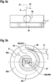
- the Fig. 5b also shows the first and second fixed movement ranges of the control rod element 5, which in the present case correspond to the two guide tracks 6a, 6b, as well as the first and second total movement ranges B6a, B6b of the control rod element 5.
- both end points 6a1, 6a2 of the first guide track 6a and a second end point 6b2 of the second guide track 6b are arranged on a common diameter D with respect to the common axis of rotation A1; They therefore each have the same distance to the axis A1.
- a center point 6am, which is arranged to divide the guideway 6a into two equal halves, and a first end point of the second guideway 6b are in the same position with respect to one another and positionally identical to the common axis of rotation A1.
- the first B6a and the second entire movement range B6b are presently congruent and correspond to a circular content of a circle with the diameter D.
- the spiral according to the present second guideway is an Archimedean spiral, wherein the angle ⁇ comprises a range of 0 to 2 ⁇ .
- the Figures 3d to 3h also show various movements, which can be imaged by means of the control device 1.
- said elements 4a, 4b and 5 move to each other Not.
- all three elements 4a, 4b and 5 together move in relation to the housing 7 and to the drive elements 8a, 8b, 9a, 9b.
- this rotational movement RO is used to steer the vehicle 3.
- a pure translational movement T1, T2 is shown in different directions.
- the first control disk 4a does not move in relation to the housing 7 and to the drive elements 8a, 8b, 9a, 9b.
- both the second control disk 4b move in relation to the first control disk 4a and the control rod member 5 in relation to the first 4a and the second control disk 4b.
- this translational movement T1, T2 is used to accelerate the vehicle 3.
- the housing 7 and the drive elements 8a, 8b, 9a, 9b are arranged rigidly relative to each other at least with respect to a position of the axes of the motors M1, M2, M3, M4 of the drive elements 8a, 8b, 9a, 9b.
- the two control discs 4a, 4b are spaced here and arranged parallel to one another in the direction of the axis A1 (see Fig. 2 ). Furthermore, the control rod element 5 is always orthogonal to a flat extension of the two control disks 4a, 4b with regard to its longitudinal direction 5z. In the present case, the longitudinal direction 5z and the common axis of rotation A1 coincide.
- Fig. 5b further shows that an orthogonal O of the first guide track 6a and a tangent T of the second guide track 6b at the position of the control rod member 5 form an angle ⁇ of 5 °; this applies in the present case to all conceivable positions of the control rod element 5.
- FIG Fig. 5a Both guideways 6a, 6b projected in the direction of the axis A1 parallel to each other.
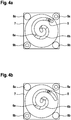
- FIGS. 4a-4g the control unit 1 is shown from below
- a sequence of movements of the control rod member 5 along the first guide track 6a wherein the position of the first control disc 4a in relation to the housing 7 here rigid remains. It can be seen that in order to exercise this movement, the second control disk 4b has to rotate accordingly, so that the control rod element 5 is always securely mounted.
- FIGS. 4a-4g It can be seen that in none of the relative positions of the first guide track 4a to the second guide track 4b, these two guide tracks 4a, 4b are arranged parallel to one another. According to the Fig. 4g the control rod member 5 is arranged so as to be aligned with the common axis A1.
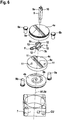
- FIGS. 3b . 3c and FIG. 6 show that the first 4a and the second control disk 4b can be actively activated with respect to a rotational movement about the axis A1 by means of two drive elements 8a, 8b, 9a, 9b.
- driven tooth elements are arranged on the outer circumference U4a, U4b of the two control disks 4a, 4b, which are in operative connection with drive tooth elements of the drive elements 8a, 8b, 9a, 9b (in accordance with FIG Fig. 3b and 3b shown only schematically; according to Fig. 6 the schematically illustrated output gear elements and drive tooth elements are each arranged on a common pitch circle).
- These drive tooth elements are in turn connected to stepper motors M1, M2, M3, M4 of the drive elements 8a, 8b, 9a, 9b, by the movement of a movement of the drive tooth elements can be achieved.
- a reset element F (see Fig. 2 and 6 ), by means of which the control rod element 5 is passively traceable to a starting position.
- the starting position is the position which corresponds to the position of the control rod element 5 on the common axis of rotation A1.
- the return element F is designed as a leg spring, one leg of which is rigid and whose other leg can be deflected by a movement of the control rod element 5 against a restoring force.
- a sensor 10 for detecting a movement direction V1 (see Fig. 5a ) of the control rod member 5 on the control rod member 5 and a control unit CU (see Fig. 2 and 6 ).
- a signal can be transmitted to the higher-order control unit CU by means of the sensor 10. This then calculates at least one signal which can be forwarded to one or more of the drive elements 8a, 8b, 9a, 9b.
- a movement of the control rod member 5 in the detected direction of movement V1 can be supported or braked.
- a housing 7 is arranged (see Fig. 2 ), within which the two control discs 4a, 4b, the drive elements 8a, 8b, 9a, 9b and the return element F are stored. Also, the control unit CU is disposed within the housing.
- the control rod element 5 comprises three elements 5a, 5b, 5c.
- the first element 5a is arranged substantially above the two control disks 6a, 6b and serves the user as a handle.
- a shaft element is formed, which is rotatably mounted to a second element 5 b of the control rod element 5.
- a third element 5c is arranged in the form of a shaft element, wherein the control rod element 5 is displaceably arranged within the second guide track 6b by means of the third element 5c.
- the second element 5b also has two inner rail-like sections 12, by means of which it is displaceably mounted between the first control disk 6a and an intermediate disk 4c or the intermediate disk 4c and the second control disk 6b (see FIG Fig. 2 ). Gaps between the first control disk 6a and the intermediate disk 4c and between the intermediate disk 4c and the second control disk 6b thus form guide rail-like sections for guiding the inner rail-like sections 12.
- the intermediate disc 4c also has a guide track 6c, which in the present case is configured identically to the first guide track 6a.
- Fig. 6 further shows three positioning elements 11, by means of which a position of the washer 4c in relation to the first control disk 4a can be locked.
- the intermediate disc 4c has a recess, within which the return element F can be arranged. A planar extension of the return element F and the recess of the intermediate disc 4c is arranged parallel to the flat extent of the discs 4a, 4b, 4c.
Landscapes
- Engineering & Computer Science (AREA)
- Physics & Mathematics (AREA)
- Automation & Control Theory (AREA)
- General Physics & Mathematics (AREA)
- General Engineering & Computer Science (AREA)
- Structural Engineering (AREA)
- Civil Engineering (AREA)
- Mining & Mineral Resources (AREA)
- Chemical & Material Sciences (AREA)
- Combustion & Propulsion (AREA)
- Transportation (AREA)
- Mechanical Engineering (AREA)
- Mechanical Control Devices (AREA)
Abstract
Description
- Die Erfindung betrifft eine manuell bedienbare Steuereinrichtung zum Ansteuern bewegbarer Elemente eines Fahrzeugs, gemäß dem Oberbegriff des Patentanspruches 1, und ein Fahrzeug gemäß dem Oberbegriff des Patentanspruches 10.
- Fahrzeuge, die mit mehreren bewegbaren Elementen im Sinne von Funktionsbauteilen oder -baugruppen ausgestattet sind, verfügen herkömmlicherweise über Steuerelemente zur Ansteuerung dieser bewegbaren Elemente. Als Beispiele für solche Fahrzeuge seien hier ein Traktor, ein Gabelstapler oder auch ein Bagger als Aushubmaschine genannt. Der Traktor umfasst beispielsweise einen Frontlader, welcher mit einem ersten Ende schwenkbar am Traktor angeordnet ist. Am zweiten Ende ist beispielsweise eine Schaufel oder eine Gabel verschwenkbar angeordnet. Zwischen dem ersten und dem zweiten Ende sind beispielsweise mehrere Holme angeordnet, welche gegeneinander ebenfalls um mehrere Achsen verschwenkbar sein können.
- Zur Ansteuerung von bewegbaren Elementen bzw. deren Bewegungsfunktionen sind aus dem Stand der Technik sogenannte Joysticks oder auch Steuerstangen bekannt, welche vom Benutzer des Fahrzeugs manuell bedienbar innerhalb der Fahrzeugkabine angeordnet sind. Das Problem bei den herkömmlichen Joysticks ist, dass die Bewegung, die der Fahrzeugführer zur Bewegung des Joysticks durchführen muss, bei mehrstündigen Schichten, wie sie bei der Feldarbeit oder dergleichen üblich sind, zu Überbeanspruchung, Ermüdungen, Missempfindung und Schmerzen vor allem in der Schulter des Benutzers des Fahrzeugs führen kann.
- Gleichermaßen befasst sich die vorliegende Erfindung mit Steuereinrichtungen zur Lenkung und/ oder Beschleunigung von Fahrzeugen, insbesondere von Geländefahrzeugen (im Englischen auch "off-road vehicles" genannt).
- Aufgabe der vorliegenden Erfindung ist es also, die herkömmlichen Steuervorrichtungen soweit weiterzuentwickeln, dass damit ein weitgehend ermüdungs- und schmerzfreies Arbeiten möglich ist. Außerdem soll es ermöglicht werden, das Steuerelement mittels der erfindungsgemäßen Steuereinrichtung in einer Position zu halten.
- Gelöst wird diese Aufgabe gemäß den Merkmalen des Patentanspruches 1 und den Merkmalen des Patentanspruches 10.
- Ein wesentlicher Punkt der Erfindung liegt darin, dass eine manuell bedienbare Steuereinrichtung zum Ansteuern bewegbarer Elemente eines Fahrzeugs und/ oder zum Lenken oder Beschleunigen eines Fahrzeugs vorgesehen ist, umfassend ein Steuerstangenelement, welches innerhalb einer ersten Führungsbahn einer ersten Steuerscheibe und innerhalb einer zweiten Führungsbahn einer zweiten Steuerscheibe verschiebbar gelagert ist, wobei die erste Führungsbahn unterschiedlich zur zweiten Führungsbahn ausgestaltet ist und die beiden Steuerscheiben unabhängig voneinander um eine gemeinsame Achse endlos drehbar gelagert sind.
- Durch die unterschiedliche Ausgestaltung der beiden Führungsbahnen kann nämlich vorteilhaft das Steuerstangenelement in seiner aktuellen Position gehalten werden, da es durch die Führung durch beide Führungsbahnen sicher gelagert wird. Zusätzlich dazu ist das Steuerstangenelement vorteilhaft mittels einer Drehung der beiden Steuerscheiben innerhalb der Führungsbahnen führbar.
- Im Sinne der vorliegenden Erfindung wird die Position des Steuerstangenelements in Relation zur ersten und/ oder zur zweiten Steuerscheibe vorteilhaft in Polarkoordinaten angegeben. Ein Polarkoordinatensystem (auch: Kreiskoordinatensystem) ist ein zweidimensionales Koordinatensystem, in dem jeder Punkt in einer Ebene (beispielsweise vorliegend ein Positionspunkt des Steuerstangenelements in Relation zu einer Oberfläche, welche durch eine flächige Ausdehnung mindestens einer der beiden Steuerscheiben resultiert) durch einen Abstand r von einem vorgegebenen festen Punkt und einem Winkel ϕ zu einer festen Richtung festgelegt wird.
- Beispielsweise entspricht der feste Punkt (auch Pol genannt) vorliegend der Position der gemeinsamen Achse bzw. Drehachse der beiden Steuerscheiben. Ferner entspricht beispielsweise eine frei wählbare Achse durch den festen Punkt der festen Richtung. Der Strahl zwischen dem Pol und dem Positionspunkt wird als Polarachse bezeichnet. Der Abstand r vom Pol wird als Radialkoordinate bezeichnet. Der Winkel ϕ wird als Winkelkoordinate bezeichnet.
- Das Steuerstangenelement ist seitens eines Benutzers des Fahrzeugs bevorzugt manuell bedienbar. Die Gestaltung hinsichtlich einer endlosen Drehbarkeit der beiden Steuerscheiben sorgt für größtmögliche Flexibilität der abbildbaren Bewegungen. Bevorzugt ist die Drehbarkeit beider Steuerscheiben in beide Drehrichtungen endlos ausgestaltet. Durch die gemeinsame Drehachse kann die Bewegung der beiden Steuerscheiben vorteilhaft aufeinander abgestimmt werden.
- Weiterhin bevorzugt ist das Steuerstangenelement zwar innerhalb der Führungsbahnen verschiebbar, jedoch gegenüber den Steuerscheiben und den Führungsbahnen nichtverschwenkbar angeordnet.
- Dabei ist die gemeinsame Drehachse der beiden Steuerscheiben bevorzugt nur virtuell angeordnet, so dass insbesondere die Steuerscheiben an einer Position der gemeinsamen Drehachse frei von Elementen zu ihrer Drehlagerung sind. Weiter bevorzugt entspricht die gemeinsamen Drehachse dem Mittelpunkt der ersten und/ oder der zweiten Steuerscheibe; beispielsweise weisen die beiden Steuerscheiben im Wesentlichen eine Kreisform auf.
- Bevorzugt ist ausgehend vom Steuerstangenelement zunächst die erste Steuerscheibe und dann die zweite Steuerscheibe in Richtung der gemeinsamen Achse angeordnet.
- Die erste und/ oder die zweite Führungsbahn entsprechen beispielsweise einer Bahn, wie sie entsteht, wenn ein Rechteck oder ein Kreis mit einem bestimmten Durchmesser entlang jeweils einer Leitkurve entlang gezogen wird. Bevorzugt ist zumindest eine oder beide der Leitkurven jeweils zweidimensional.
- Dabei ist es vorteilhaft, wenn die erste Führungsbahn eine geradlinige Form aufweist und/ oder durch die Achse verlaufend angeordnet ist.
- Bevorzugt ist also die Relativbewegung zwischen dem Steuerstangenelement und der ersten Steuerscheibe eine reine Translationsbewegung. Wenn die erste Führungsbahn durch die gemeinsame Drehachse verläuft und das Steuerstangenelement an der Position der gemeinsamen Drehachse ist, so ist an diesem Punkt mittels einer Drehung der Steuerscheiben keine Bewegung des Steuerstangenelements auslösbar.
- Wenn die gemeinsame Drehachse den Mittelpunkt der Steuerscheibe ausbildet und gleichzeitig die erste Führungsbahn eine geradlinige Form aufweist und durch die gemeinsame Drehachse verlaufend angeordnet ist, so ist mittels einer Relativbewegung zwischen erster Steuerscheibe und Steuerstangenelement jeder Punkt auf der Steuerscheibe abbildbar. Mit anderen Worten kann das Steuerstangenelement, insbesondere dessen Mittelpunkt oder dessen Mittelachse, unter den genannten Bedingungen jeden Punkt innerhalb des Umfangs der ersten Steuerscheibe anfahren. Möglich ist natürlich, dass hiervon die Punkte ganz außen am Umfang der ersten Steuerscheibe ausgenommen sind, wenn die flächige Ausdehnung des Steuerstangenelements in Richtung der flächigen Ausdehnung der ersten Steuerscheibe ein Anfahren der äußeren Punkte der Steuerscheibe mittels des Steuerstangenelements verhindert.
- Weiterhin ist es bevorzugt, wenn die zweite Führungsbahn in Form einer Spirale ausgestaltet ist und/ oder durch die gemeinsame Achse verlaufend angeordnet ist.
- Dabei verläuft die Spirale entlang einer zweidimensionalen Kurve, die ausgehend von ihren Startpunkt um die gemeinsame Achse verlaufend und sich von dieser entfernend ausgestaltet ist.
- Durch die Spiralform ist gewährleistet, dass entlang der Radialrichtung der zweiten Steuerscheibe mittels des Steuerstangenelements eine Vielzahl an Positionspunkten auf der zweiten Steuerscheibe abbildbar ist.
- Im Sinne der vorliegenden Erfindung wird unter der Gesamtheit der Positionspunkte, die das Steuerstangenelement im Zusammenspiel mit der ersten Steuerscheibe abbilden kann, ein erster fixer und ein erster gesamter Bewegungsbereich (für die Bewegung des Steuerstangenelements auf der ersten Steuerscheibe bei fixer und bei sich drehender Steuerscheibe) verstanden. Analog dazu wird unter der Gesamtheit der Punkte, die das Steuerstangenelement im Zusammenspiel mit der zweiten Steuerscheibe abbilden kann, ein zweiter fixer und ein zweiter gesamter Bewegungsbereich (für die Bewegung des Steuerstangenelements auf der ersten Steuerscheibe bei fixer und bei sich drehender Steuerscheibe) verstanden.
- Dabei entsprechen die ersten und zweiten fixen Bewegungsbereiche der ersten bzw. zweiten Führungsbahn. Die ersten und zweiten gesamten Bewegungsbereiche entsprechen vorteilhaft einem Kreisinhalt. Vorteilhaft ist der zugrunde liegende Kreis für beide Bewegungsbereiche mit gleichem Durchmesser ausgestaltet.
- Bevorzugt ist die erste Führungsbahn so ausgestaltet, dass ein erster Endpunkt und ein zweiter Endpunkt der ersten Führungsbahn benachbart zum Außenumfang der ersten Steuerscheibe angeordnet sind. Im Sinne der vorliegenden Erfindung wird unter "benachbart" hier verstanden, dass ein Wert der Radialkoordinate des ersten und zweiten Endpunkts mindestens 90% des Radiuswertes der ersten Steuerscheibe beträgt. Mit anderen Worten gilt bevorzugt, dass r einen Bereich von 0 bis 0,9.R1 umfasst, wobei R1 der Radius der ersten Steuerscheibe ist.
- Bevorzugt ist die zweite Führungsbahn so ausgestaltet, dass ein erster Endpunkt der zweiten Führungsbahn fluchtend zur gemeinsamen Achse angeordnet und ein zweiter Endpunkt benachbart zum Außenumfang der zweiten Steuerscheibe angeordnet ist. Im Sinne der vorliegenden Erfindung wird unter "benachbart" hier verstanden, dass ein Wert der Radialkoordinate des zweiten Endpunkts mindestens 90% des Radiuswertes der zweiten Steuerscheibe beträgt. Mit anderen Worten gilt bevorzugt, dass r einen Bereich von 0 bis 0,9·R2 umfasst, wobei R2 der Radius der zweiten Steuerscheibe ist.
- Weiter bevorzugt weisen beide Radien R1 und R2 einen gleichen Wert auf.
- Weiter bevorzugt ist die Spirale eine archimedische Spirale; das heißt, die Koordinaten eines Punkts auf der Spirale lassen sich mittels der Formel r = a·ϕ berechnen, wobei a eine Konstante ist. Mit anderen Worten gilt bevorzugt, dass der Quotient aus r und ϕ konstant ist.
- Ferner ist es bevorzugt, wenn ein Winkel zwischen einer Linie, welche durch einen beliebigen Punkt auf der Spirale und senkrecht zu dessen Radialkoordinate verläuft, und einer Tangente, welche durch den beliebigen Punkt und tangential zur Spirale verläuft, einen Wert aus einem Bereich von 2° bis 10°, weiter bevorzugt von 3° bis 7°, meist bevorzugt von 5° aufweist.
- Ferner gilt bevorzugt, dass ϕ einen Bereich umfasst, dessen Anfang bei 0 liegt und dessen Ende in einem Bereich liegt, welcher 1,5π bis 2,5π umfasst. Bevorzugt ist das Ende bei 2π; die Spirale verläuft also genau einmal im Kreis herum bzw. einmal entlang des Umfangs der zweiten Steuerscheibe.
- In diesem Fall ist es beispielsweise denkbar, dass der zuvor beschriebene Winkel zwischen der Linie, welche durch einen beliebigen Punkt auf der Spirale und senkrecht zu dessen Radialkoordinate verläuft, und der Tangente, welche durch den beliebigen Punkt und tangential zur Spirale verläuft, nur in einem Bereich von 0 bis 1,5π einen konstanten Wert aufweist. Bevorzugt ist der Winkel im Bereich von 1,5π bis 2π größer als im Bereich von 0 bis 1,5π. Soll in diesem Fall für alle Bereiche gelten, dass die Spirale eine archimedische Spirale ist, gilt für den Bereich von 0 bis 1,5π die Konstante a1 und für den Bereich 1,5π bis 2π die Konstante a2, wobei a2 bevorzugt kleiner als a1 ist.
- In der Praxis hat es sich als vorteilhaft herausgestellt, wenn die beiden Steuerscheiben beabstandet und parallel zueinander verlaufend angeordnet sind und/ oder das Steuerstangenelement hinsichtlich seiner Längsrichtung stets orthogonal zu einer flächigen Ausdehnung mindestens einer der beiden Steuerscheiben angeordnet ist.
- Diese Anordnung bietet dem Benutzer der Steuereinrichtung Platz, um mit einer Hand das Steuerstangenelement zu greifen, ohne dass sein Unterarm mit einer der Steuerscheiben kollidiert.
- Ferner ist es bevorzugt, wenn die beiden Steuerscheiben hinsichtlich ihres Außenumfangs kongruent zueinander ausgebildet sind.
- Es gilt weiterhin, dass bevorzugt in keiner mittels der Steuerungseinrichtung einstellbaren Relativposition der ersten Führungsbahn zur zweiten Führungsbahn diese beiden Führungsbahnen projiziert auf deren flächige Ausdehnung parallel zueinander angeordnet sind. Bevorzugt ist, dass die erste Führungsbahn und eine Tangente der zweiten Führungsbahn an der Position des Steuerstangenelements stets einen Winkel aus einem Bereich von 2 bis 10°, bevorzugt von 5° ausbilden. Dahingegen sind beide Führungsbahnen projiziert auf eine Höhenrichtung der Steuerungseinrichtung, welche bevorzugt der Längsrichtung des Steuerstangenelements entspricht, bevorzugt parallel zueinander angeordnet.
- Bevorzugt weisen die beiden Führungsbahnen weiterhin jeweils mindestens einen Endpunkt auf, welcher den gleichen Abstand zur gemeinsamen Drehachse aufweist. Bevorzugt weisen beide Endpunkte der ersten Führungsbahn und ein zweiter Endpunkt der zweiten Führungsbahn den gleichen Abstand zur gemeinsamen Drehachse auf.
- Um die Bedienung der Steuereinrichtung zu erleichtern, hat es sich insbesondere als vorteilhaft herausgestellt, wenn die erste und/ oder die zweite Steuerscheibe hinsichtlich einer Drehbewegung um die gemeinsame Drehachse jeweils mittels mindestens eines Antriebselements aktiv ansteuerbar sind. Das bedeutet insbesondere, dass eine Bewegung des Steuerstangenelements innerhalb der beiden gesamten Bewegungsbereiche aktiv unterstützbar ist.
- Vorteilhaft sind die Antriebselemente so ausgestaltet, dass sie mit dem Außenumfang der beiden Steuerscheiben in Wirkverbindung stehen. Beispielsweise sind am Außenumfang der beiden Steuerscheiben Abtriebszahnelemente angeordnet, welche mit Antriebszahnelementen der Antriebselemente in Wirkverbindung stehen. Weiter bevorzugt umfassen die Antriebselemente neben den Antriebzahnelementen bürstenlose Gleichstrommotoren (BLDC) oder Schrittmotoren. Der Vorteil eines Schrittmotors ist beispielsweise, dass sich eine Drehung der Motorachsen und damit verbundener Elemente, wie beispielsweise der Antriebszahnelemente, hinsichtlich des einzustellenden Drehwinkels genau steuern lässt.
- Um den Benutzer der Steuereinrichtung weiterhin zu entlasten, ist es vorteilhaft, wenn ein Rückstellelement angeordnet ist, mittels welchem das Steuerstangenelement passiv in eine Ausgangsstellung rückführbar ist. Dabei ist die Ausgangsstellung des Steuerstangenelements beispielsweise die Position, welcher der gemeinsamen Achse der Steuerscheiben entspricht. Das Rückstellelement ist beispielsweise als Schenkelfeder ausgestaltet, deren einer Schenkel starr gelagert ist und deren anderer Schenkel durch eine Bewegung des Steuerstangenelements gegen eine Rückstellkraft auslenkbar ist.
- Außerdem ist es vorteilhaft, wenn ein Sensor zur Detektion einer Bewegungsrichtung des Steuerstangenelements am Steuerstangenelement und eine Steuerungseinheit angeordnet sind. In diesem Fall ist mittels des Sensors ein Signal an die übergeordnete Steuerungseinheit übermittelbar. Die Steuerungseinheit ist beispielsweise in Form einer SPS (Speicherprogrammierbare Steuerung) ausgestaltet. Eine SPS hat beispielsweise (Signal-)Eingänge, (Signal-)Ausgänge, ein Betriebssystem oder auch Firmware und eine Schnittstelle, über die ein Anwenderprogramm geladen werden kann. Das Anwenderprogramm legt fest, wie die Ausgänge in Abhängigkeit von den Eingängen geschaltet werden sollen.
- Des Weiteren ist es vorteilhaft, wenn Signale des Sensors mittels der Steuerungseinheit in Signale an das mindestens eine Antriebselement der ersten/ und oder der zweiten Steuerscheibe übermittelbar sind. Diese Steuerungseinheit berechnet dann, beispielsweise mit Hilfe des Anwenderprogramms, mindestens ein Signal, welches an eines oder mehrere der Antriebselemente weitergebbar ist. Somit ist beispielsweise eine Bewegung des Steuerstangenelements in die detektierte Bewegungsrichtung unterstützbar (oder beschleunigbar) oder auch abbremsbar (oder verzögerbar).
- Ferner ist es vorteilhaft, wenn ein Gehäuse angeordnet ist, innerhalb welchem die beiden Steuerscheiben, das jeweils mindestens eine Antriebselement und das Rückstellelement gelagert sind. Dies ist vorteilhaft, da die Lagerung der Elemente zueinander vorteilhaft mittels des Gehäuses ausgestaltet werden kann.
- Die Aufgabe der Erfindung wird auch gelöst durch ein Fahrzeug, das mittels einer manuell bedienbaren Steuereinrichtung gemäß einem der Ansprüche 1-9 lenk- und/ oder beschleunigbar ist, und wird ferner gelöst durch ein Fahrzeug mit bewegbaren Elementen, welche mittels einer manuell bedienbaren Steuereinrichtung gemäß einem der Ansprüche 1-9 ansteuerbar sind.
- Vorteilhafte Ausführungsformen ergeben sich aus den Unteransprüchen.
- Vorteile und Zweckmäßigkeiten sind der nachfolgenden Beschreibung in Verbindung mit der Zeichnung zu entnehmen.
- Es zeigen:
- Fig. 1
- ein Fahrzeug mit bewegbaren Elementen;
- Fig. 2
- eine dreidimensionale Darstellung einer erfindungsgemäßen Steuereinrichtung;
- Fig. 3a-h
- weitere dreidimensionale Darstellungen der erfindungsgemäßen Steuereinrichtung gemäß
Fig. 2 ; - Fig. 4a-g
- Darstellungen verschiedener Positionspunkte des Steuerstangenelements;
- Fig. 5a, 5b
- Darstellungen der ersten und der zweiten Führungsbahn;
- Fig. 6
- eine Explosionsdarstellung der erfindungsgemäßen Steuereinrichtung gemäß
Fig. 2 ; - Gemäß
Fig. 1 ist ein Fahrzeug 3 mit bewegbaren Elementen 2a, 2b, 2c gezeigt, wovon mindestens eines mittels einer manuell bedienbaren Steuereinrichtung 1 (nur schematisch im Fahrzeuginneren veranschaulicht) ansteuerbar ist. Vorliegend ist das Fahrzeug 3 ein Traktor und die bewegbaren Elemente beispielsweise der erste Holm 2a, der zweite Holm 2b oder nur die Schaufel 2c des Frontladers oder aber alle drei Elemente 2a, 2b, 2c. Ebenfalls möglich wäre, dass ein Pflug oder ein anderes Werkzeug (nicht gezeigt), welches beispielsweise mittels einer 3-Punkt-Anhängerkupplung an dem Traktor befestigt ist, eines der bewegbaren Elemente darstellt. - Gemäß der
Fig. 2 ist die manuell bedienbare Steuereinrichtung 1 zum Ansteuern bewegbarer Elemente 2a, 2b, 2c eines Fahrzeugs 3 und/ oder zum Lenken und/ oder Beschleunigen des Fahrzeugs 3 in einer perspektivischen Ansicht gezeigt, umfassend ein Steuerstangenelement 5, welches innerhalb einer ersten Führungsbahn 6a einer ersten Steuerscheibe 4a und innerhalb einer zweiten Führungsbahn 6b (sieheFig. 6 ) einer zweiten Steuerscheibe 4b (sieheFig. 6 ) verschiebbar gelagert ist, wobei die erste Führungsbahn 6a unterschiedlich zur zweiten Führungsbahn 6b ausgestaltet ist und die beiden Steuerscheiben 4a, 4b unabhängig voneinander um eine gemeinsame Achse A1 endlos drehbar gelagert sind. - Vorliegend entspricht der feste Punkt der dem Steuerstangenelement 5 zugeordneten Polarkoordinaten vorliegend der Position der gemeinsamen Drehachse A1 der beiden Steuerscheiben 4a, 4b.
- Das Steuerstangenelement 5 ist seitens eines Benutzers des Fahrzeugs 3 manuell bedienbar. Dabei ist die Drehachse A1 vorliegend nur virtuell angeordnet, so dass die Steuerscheiben 4a, 4b an einer Position der Drehachse A1 frei von Elementen zu ihrer Drehlagerung sind. Vorliegend entspricht die erste Drehachse A1 dem Mittelpunkt der ersten 4a und dem Mittelpunkt der zweiten Steuerscheibe 4b.
- Die erste 6a und die zweite Führungsbahn 6b entsprechen dabei einer Bahn, wie sie entsteht, wenn ein Rechteck (erste Führungsbahn 6a) oder ein Kreis (zweite Führungsbahn 6b) mit einem bestimmten Durchmesser entlang jeweils einer Leitkurve entlang gezogen wird. Dabei ist die Leitkurve jeweils zweidimensional.
- Dabei weist die erste Führungsbahn 6a eine geradlinige Form auf und ist durch die Achse A1 verlaufend angeordnet. Die Relativbewegung zwischen dem Steuerstangenelement 5 und der ersten Steuerscheibe 4a ist daher eine reine Translationsbewegung. Da die erste Führungsbahn 6a vorliegend durch die gemeinsame Drehachse A1 verläuft und das Steuerstangenelement 5 gemäß der
Fig. 2 an der Position der gemeinsamen Drehachse A1 ist, ist in diesem Fall mittels einer Drehung der Steuerscheiben 4a, 4b keine Relativbewegung des Steuerstangenelements 5 gegenüber einer der Steuerscheiben 4a, 4b auslösbar. - Da die gemeinsame Drehachse A1 den Mittelpunkt der ersten Steuerscheibe 4a ausbildet und gleichzeitig die erste Führungsbahn 6a eine geradlinige Form aufweist und durch die Drehachse A1 verlaufend angeordnet ist, ist mittels einer Relativbewegung zwischen erster Steuerscheibe 4a und Steuerstangenelement 5 und mittels einer Relativbewegung zwischen erster Steuerscheibe 4a und dem Gehäuse 7 jeder Punkt auf der Steuerscheibe abbildbar.
- Mit anderen Worten kann das Steuerstangenelement 5, insbesondere dessen Mittelpunkt oder dessen Mittelachse, unter den genannten Bedingungen jeden Punkt innerhalb des Umfangs U4a der ersten Steuerscheibe 4a anfahren. Hiervon ausgenommen sind die Punkte ganz außen am Umfang U4a der ersten Steuerscheibe 4a, da die flächige Ausdehnung des Steuerstangenelements 5 in Richtung der flächigen Ausdehnung der ersten Steuerscheibe 4a ein Anfahren der äußeren Punkte der Steuerscheibe 4a mittels des Steuerstangenelements 5 verhindert.
- Gemäß den
Fig. 5b und6 ist außerdem gezeigt, dass die zweite Führungsbahn 6b in Form einer Spirale ausgestaltet ist und durch die Achse A1 verlaufend angeordnet ist. Dabei folgt die Spirale einer Kurve, die ausgehend von der Achse A1 um die Achse A1 verlaufend und sich von dieser entfernend ausgestaltet ist. - Die
Fig. 5b zeigt außerdem die ersten und zweiten fixen Bewegungsbereiche des Steuerstangenelements 5, welche vorliegend den beiden Führungsbahnen 6a, 6b entsprechen, sowie die ersten und zweiten gesamten Bewegungsbereiche B6a, B6b des Steuerstangenelements 5. - Vorliegend sind beide Endpunkte 6a1, 6a2 der ersten Führungsbahn 6a und ein zweiter Endpunkt 6b2 der zweiten Führungsbahn 6b auf einem gemeinsamen Durchmesser D in Bezug auf die gemeinsame Drehachse A1 angeordnet; sie weisen also jeweils den gleichen Abstand zur Achse A1 auf. Ein Mittenpunkt 6am, welcher die Führungsbahn 6a in zwei gleiche Hälften teilend angeordnet ist, und ein erster Endpunkt der zweiten Führungsbahn 6b sind dabei positionsgleich zueinander und positionsgleich zur gemeinsamen Drehachse A1.
- Bei der Darstellung der Endpunkte wurde berücksichtigt, dass die Teile des Steuerstangenelements 5, welche innerhalb der Führungsbahnen 6a, 6b geführt werden, eine flächige Ausdehnung besitzen. Daher fällt die Berandung der Führungsbahnen 6a, 6b nicht mit den Endpunkten 6a1, 6a2, 6b1, 6b2 zusammen.
- Der erste B6a und der zweite gesamte Bewegungsbereich B6b sind vorliegend kongruent und entsprechen einem Kreisinhalt eines Kreises mit dem Durchmesser D.
- Die Spirale gemäß der vorliegenden zweiten Führungsbahn ist eine archimedische Spirale, wobei der Winkel ϕ einen Bereich von 0 bis 2π umfasst.
- Die
Figuren 3d bis 3h zeigen außerdem verschiedene Bewegungen, welche mittels der Steuereinrichtung 1 abbildbar sind. Gemäß derFig. 3d ist eine reine Rotationsbewegung RO des Steuerstangenelements 5 gemeinsam mit den beiden Steuerscheiben 4a, 4b gezeigt. Bei dieser Bewegung RO bewegen sich die genannten Elemente 4a, 4b und 5 zueinander nicht. Alle drei Elemente 4a, 4b und 5 zusammen bewegen sich jedoch in Relation zum Gehäuse 7 und zu den Antriebselementen 8a, 8b, 9a, 9b. Beispielsweise wird diese Rotationsbewegung RO zur Lenkung des Fahrzeugs 3 eingesetzt. - Gemäß den
Figuren 3e und 3f ist jeweils eine reine Translationsbewegung T1, T2 in verschiedene Richtungen gezeigt. Dabei bewegt sich die erste Steuerscheibe 4a in Relation zum Gehäuse 7 und zu den Antriebselementen 8a, 8b, 9a, 9b nicht. Es bewegen sich jedoch sowohl die zweite Steuerscheibe 4b in Relation zur ersten Steuerscheibe 4a als auch das Steuerstangenelement 5 in Relation zur ersten 4a und zur zweiten Steuerscheibe 4b. Beispielsweise wird diese Translationsbewegung T1, T2 zur Beschleunigung des Fahrzeugs 3 eingesetzt. - Schließlich veranschaulichen die
Figuren 3g und 3h jeweils eine kombinierte Bewegung K1, K2. Dabei bewegen sich die Elemente 4a, 4b, 5 jeweils zueinander und auch in Relation zum Gehäuse 7 und zu den Antriebselementen 8a, 8b, 9a, 9b. - Das Gehäuse 7 und die Antriebselemente 8a, 8b, 9a, 9b sind dabei zueinander zumindest hinsichtlich einer Position der Achsen der Motoren M1, M2, M3, M4 der Antriebselemente 8a, 8b, 9a, 9b starr angeordnet.
- Die beiden Steuerscheiben 4a, 4b sind vorliegend beabstandet und in Richtung der Achse A1 parallel zueinander verlaufend angeordnet (siehe
Fig. 2 ). Ferner ist das Steuerstangenelement 5 hinsichtlich seiner Längsrichtung 5z stets orthogonal zu einer flächigen Ausdehnung der beiden Steuerscheiben 4a, 4b angeordnet. Vorliegend fallen die Längsrichtung 5z und die gemeinsame Drehachse A1 zusammen. -
Fig. 5b zeigt weiterhin, dass eine Orthogonale O der ersten Führungsbahn 6a und eine Tangente T der zweiten Führungsbahn 6b an der Position des Steuerstangenelements 5 einen Winkel α von 5° ausbilden; dies gilt vorliegend für alle denkbaren Positionen des Steuerstangenelements 5. Dahingegen sind gemäßFig. 5a beide Führungsbahnen 6a, 6b projiziert auf Richtung der Achse A1 parallel zueinander angeordnet. - Gemäß den
Figuren 4a-4g (hier ist die Steuereinheit 1 von unten gezeigt) ist weiterhin eine Bewegungsabfolge des Steuerstangenelements 5 entlang der ersten Führungsbahn 6a gezeigt, wobei die Position der ersten Steuerscheibe 4a in Relation zum Gehäuse 7 hier starr bleibt. Zu sehen ist, dass zur Ausübung dieser Bewegung sich die zweite Steuerscheibe 4b entsprechend mitdrehen muss, so dass das Steuerstangenelement 5 immer sicher gelagert ist. - Ebenfalls gemäß den
Figuren 4a-4g zu sehen ist, dass in keiner gezeigten Relativposition der ersten Führungsbahn 4a zur zweiten Führungsbahn 4b diese beiden Führungsbahnen 4a, 4b parallel zueinander angeordnet sind. Gemäß derFig. 4g ist das Steuerstangenelement 5 so angeordnet, dass es mit der gemeinsamen Achse A1 fluchtet. - Die
Figuren 3b ,3c sowie 6 zeigen, dass die erste 4a und die zweite Steuerscheibe 4b hinsichtlich einer Drehbewegung um die Achse A1 jeweils mittels zweier Antriebselemente 8a, 8b, 9a, 9b aktiv ansteuerbar sind. Dabei sind am Außenumfang U4a, U4b der beiden Steuerscheiben 4a, 4b Abtriebszahnelemente angeordnet, welche mit Antriebszahnelementen der Antriebselemente 8a, 8b, 9a, 9b in Wirkverbindung stehen (gemäßFig. 3b und 3b nur schematisch gezeigt; gemäßFig. 6 sind die schematisch veranschaulichten Abtriebszahnelemente und Antriebszahnelemente jeweils auf einem gemeinsamen Teilkreis angeordnet). Diese Antriebszahnelemente stehen wiederum in Verbindung mit Schrittmotoren M1, M2, M3, M4 der Antriebselemente 8a, 8b, 9a, 9b, durch deren Bewegung eine Bewegung der Antriebszahnelemente erzielbar ist. - Um den Benutzer der Steuereinrichtung 1 weiterhin zu entlasten, ist ein Rückstellelement F (siehe
Fig. 2 und6 ) angeordnet, mittels welchem das Steuerstangenelement 5 passiv in eine Ausgangsstellung rückführbar ist. Dabei ist die Ausgangsstellung vorliegend die Position, welcher der Position des Steuerstangenelements 5 an der gemeinsamen Drehachse A1 entspricht. Das Rückstellelement F ist als Schenkelfeder ausgestaltet, deren einer Schenkel starr ist und deren anderer Schenkel durch eine Bewegung des Steuerstangenelements 5 gegen eine Rückstellkraft auslenkbar ist. - Außerdem ist ein Sensor 10 (siehe
Fig. 2 und6 ) zur Detektion einer Bewegungsrichtung V1 (sieheFig. 5a ) des Steuerstangenelements 5 am Steuerstangenelement 5 und eine Steuerungseinheit CU angeordnet (sieheFig. 2 und6 ). In diesem Fall ist mittels des Sensors 10 ein Signal an die übergeordnete Steuerungseinheit CU übermittelbar. Diese berechnet dann mindestens ein Signal, welches an eines oder mehrere der Antriebselemente 8a, 8b, 9a, 9b weitergebbar ist. Somit ist beispielsweise eine Bewegung des Steuerstangenelements 5 in die detektierte Bewegungsrichtung V1 unterstützbar oder auch abbremsbar. - Ferner ist ein Gehäuse 7 angeordnet (siehe
Fig. 2 ), innerhalb welchem die beiden Steuerscheiben 4a, 4b, die Antriebselemente 8a, 8b, 9a, 9b und das Rückstellelement F gelagert sind. Ebenfalls ist die Steuerungseinheit CU innerhalb des Gehäuses angeordnet. - Gemäß der
Fig. 6 ist außerdem gezeigt, dass das Steuerstangenelement 5 drei Elemente 5a, 5b, 5c umfasst. Das erste Element 5a ist im Wesentlichen oberhalb der beiden Steuerscheiben 6a, 6b angeordnet und dient dem Benutzer als Handgriff. Am unteren Ende des ersten Elements 5a ist ein Wellenelement ausgebildet, welches zu einem zweiten Element 5b des Steuerstangenelements 5 drehbar gelagert ist. - Am unteren Ende des zweiten Elements 5b ist ein drittes Element 5c in Form eines Wellenelements angeordnet, wobei das Steuerstangenelement 5 mittels des dritten Elements 5c innerhalb der zweiten Führungsbahn 6b verschiebbar angeordnet ist. Das zweite Element 5b weist ferner zwei innenschienenartige Abschnitte 12 auf, mittels welchen es zwischen der ersten Steuerscheibe 6a und einer Zwischenscheibe 4c bzw. der Zwischenscheibe 4c und der zweiten Steuerscheibe 6b verschiebbar gelagert ist (siehe
Fig. 2 ). Zwischenräume zwischen der ersten Steuerscheibe 6a und der Zwischenscheibe 4c und zwischen der Zwischenscheibe 4c und der zweiten Steuerscheibe 6b bilden somit führungsschienenartige Abschnitte zum Führen der innenschienenartige Abschnitte 12 aus. - Ausgehend vom Steuerstangenelement 5 ist also zunächst die erste Steuerscheibe 4a, dann die Zwischenscheibe 4c und dann die zweite Steuerscheibe 4b in Richtung der Achse A1 angeordnet.
- Dabei weist die Zwischenscheibe 4c ebenfalls eine Führungsbahn 6c auf, welche vorliegend zur ersten Führungsbahn 6a identisch ausgestaltet ist.
Fig. 6 zeigt weiterhin drei Positionierelemente 11, mittels welcher eine Position der Zwischenscheibe 4c in Relation zur ersten Steuerscheibe 4a arretierbar ist. Ferner weist die Zwischenscheibe 4c eine Aussparung auf, innerhalb welcher das Rückstellelement F anordenbar ist. Eine flächige Ausdehnung des Rückstellelements F sowie der Aussparung der Zwischenscheibe 4c ist dabei parallel zur flächigen Ausdehnung der Scheiben 4a, 4b, 4c angeordnet. - Sämtliche in den Anmeldungsunterlagen offenbarten Merkmale werden als erfindungswesentlich beansprucht, sofern sie einzeln oder in Kombination gegenüber dem Stand der Technik neu sind.
-
- 1
- Steuereinrichtung
- 2a, 2b, 2c
- bewegbares Element
- 3
- Fahrzeug
- 4a, 4b
- Steuerscheibe
- 4c
- Zwischenscheibe
- 5
- Steuerstangenelement
- 5a, 5b, 5c
- Elemente
- 5z
- Längsrichtung
- 6a, 6b
- Führungsbahn
- 6a1, 6a2
- erster Endpunkt
- 6a2, 6b2
- zweiter Endpunkt
- 6am
- Mittenpunkt
- 7
- Gehäuse
- 8a, 8b, 9a, 9b
- Antriebselement
- 10
- Sensor
- 11
- Positionierelemente
- 12
- innenschienenartige Elemente
- A1
- gemeinsame Drehachse
- B6a, B6b
- gesamter Bewegungsbereich
- CU
- Steuerungseinheit
- D
- Durchmesser
- F
- Rückstellelement
- M1, M2, M3, M4
- Motor
- O
- Orthogonale
- T
- Tangente
- T1, T2
- Translationsbewegung
- r
- Radialkoordinate
- RO
- Rotationsbewegung
- R1, R2
- Radius der Steuerscheibe
- K1, K2
- kombinierte Bewegung
- U4a, U4b
- Umfang
- V1
- Bewegungsrichtung
- α, ϕ
- Winkel
Claims (10)
- Manuell bedienbare Steuereinrichtung (1) zum Ansteuern bewegbarer Elemente (2a, 2b, 2c) eines Fahrzeugs (3) und/ oder zum Lenken oder Beschleunigen des Fahrzeugs (3),
gekennzeichnet durch
ein Steuerstangenelement (5), welches innerhalb einer ersten Führungsbahn (6a) einer ersten Steuerscheibe (4a) und innerhalb einer zweiten Führungsbahn (6b) einer zweiten Steuerscheibe (4b) verschiebbar gelagert ist,
wobei die erste Führungsbahn (6a) unterschiedlich zur zweiten Führungsbahn (6b) ausgestaltet ist und die beiden Steuerscheiben (4a, 4b) unabhängig voneinander um eine gemeinsame Achse (A1) endlos drehbar gelagert sind. - Manuell bedienbare Steuereinrichtung (1) nach Anspruch 1,
dadurch gekennzeichnet, dass
die erste Führungsbahn (6a) eine geradlinige Form aufweist und/ oder durch die Achse (A1) verlaufend angeordnet ist. - Manuell bedienbare Steuereinrichtung (1) nach Anspruch 1 oder 2,
dadurch gekennzeichnet, dass
die zweite Führungsbahn (6b) in Form einer Spirale ausgestaltet ist und/ oder durch die Achse (A1) verlaufend angeordnet ist. - Manuell bedienbare Steuereinrichtung (1) nach einem der vorhergehenden Ansprüche,
dadurch gekennzeichnet, dass
die beiden Steuerscheiben (4a, 4b) beabstandet und parallel zueinander verlaufend angeordnet sind und/ oder das Steuerstangenelement (5) hinsichtlich seiner Längsrichtung (5z) stets orthogonal zu einer flächigen Ausdehnung mindestens einer der beiden Steuerscheiben (4a, 4b) angeordnet ist. - Manuell bedienbare Steuereinrichtung (1) nach einem der vorhergehenden Ansprüche,
dadurch gekennzeichnet, dass
die erste (4a) und/ oder die zweite Steuerscheibe (4b) hinsichtlich einer Drehbewegung um die Achse (A1) jeweils mittels mindestens eines Antriebselements (8a, 8b, 9a, 9b) aktiv ansteuerbar sind. - Manuell bedienbare Steuereinrichtung (1) nach einem der vorhergehenden Ansprüche,
dadurch gekennzeichnet, dass
ein Rückstellelement (F) angeordnet ist, mittels welchem das Steuerstangenelement (5) passiv in eine Ausgangsstellung rückführbar ist. - Manuell bedienbare Steuereinrichtung (1) nach einem der vorhergehenden Ansprüche,
dadurch gekennzeichnet, dass
ein Sensor (10) zur Detektion einer Bewegungsrichtung des Steuerstangenelements (5) am Steuerstangenelement (5) und eine Steuerungseinheit (CU) angeordnet sind. - Manuell bedienbare Steuereinrichtung (1) nach einem der vorhergehenden Ansprüche,
dadurch gekennzeichnet, dass
ein Gehäuse (7) angeordnet ist, innerhalb welchem die beiden Steuerscheiben (4a, 4b), das jeweils mindestens eine Antriebselement (8a, 8b, 9a, 9b) und das Rückstellelement (F) gelagert sind. - Manuell bedienbare Steuereinrichtung (1) nach einem der vorhergehenden Ansprüche,
dadurch gekennzeichnet, dass
Signale des Sensors (10) mittels der Steuerungseinheit (CU) in Signale an das mindestens eine Antriebselement (8a, 8b, 9a, 9b) der ersten/ und oder der zweiten Steuerscheibe (4a, 4b) übermittelbar sind. - Fahrzeug (3), das mittels einer manuell bedienbaren Steuereinrichtung (1) gemäß einem der Ansprüche 1-9 lenk- und/ oder beschleunigbar ist, oder mit mindestens einem bewegbaren Element (2a, 2b, 2c), das mittels einer manuell bedienbaren Steuereinrichtung (1) gemäß einem der Ansprüche 1-9 ansteuerbar ist.
Applications Claiming Priority (1)
| Application Number | Priority Date | Filing Date | Title |
|---|---|---|---|
| DE102017115849.9A DE102017115849B4 (de) | 2017-07-14 | 2017-07-14 | Manuell bedienbare Steuereinrichtung |
Publications (2)
| Publication Number | Publication Date |
|---|---|
| EP3428349A1 true EP3428349A1 (de) | 2019-01-16 |
| EP3428349B1 EP3428349B1 (de) | 2022-08-24 |
Family
ID=62486404
Family Applications (1)
| Application Number | Title | Priority Date | Filing Date |
|---|---|---|---|
| EP18174705.6A Active EP3428349B1 (de) | 2017-07-14 | 2018-05-29 | Manuell bedienbare steuereinrichtung |
Country Status (3)
| Country | Link |
|---|---|
| US (1) | US10678292B2 (de) |
| EP (1) | EP3428349B1 (de) |
| DE (1) | DE102017115849B4 (de) |
Families Citing this family (2)
| Publication number | Priority date | Publication date | Assignee | Title |
|---|---|---|---|---|
| US11068015B2 (en) * | 2019-05-02 | 2021-07-20 | Deere & Company | Variable track joystick devices and work vehicles containing the same |
| KR102717193B1 (ko) * | 2019-12-27 | 2024-10-14 | 에스엘 주식회사 | 차량용 제어 시스템 |
Citations (3)
| Publication number | Priority date | Publication date | Assignee | Title |
|---|---|---|---|---|
| US2488469A (en) * | 1946-06-08 | 1949-11-15 | Ford Motor Co | Tractor transmission control |
| DE19832086A1 (de) * | 1998-07-16 | 2000-01-27 | Fico Triad Sa | Schalthebeleinheit |
| JP2008239055A (ja) * | 2007-03-28 | 2008-10-09 | Tokai Rika Co Ltd | シフトレバー装置 |
Family Cites Families (14)
| Publication number | Priority date | Publication date | Assignee | Title |
|---|---|---|---|---|
| US2746573A (en) * | 1952-12-30 | 1956-05-22 | Bendix Aviat Corp | Automatic stop mechanism |
| US4158845A (en) * | 1978-03-31 | 1979-06-19 | The Boeing Company | Non-gimbaled pointer and tracking platform assembly |
| US5430511A (en) * | 1993-12-21 | 1995-07-04 | Sensormatic Electronics Corporation | Controller for a surveillance assembly |
| SE524018C2 (sv) * | 2002-10-03 | 2004-06-15 | Parker Hannifin Ab | Manöveranordning samt metod för manövrering av ett manöverobjekt |
| JP4475092B2 (ja) * | 2004-10-20 | 2010-06-09 | パナソニック株式会社 | 電子部品の中点復帰機構、およびそれを用いた入力操作用電子部品 |
| US20070068785A1 (en) * | 2005-09-26 | 2007-03-29 | Taiwan Pwl Corporation | Rocker level assembly |
| ES2362948T3 (es) * | 2007-11-26 | 2011-07-15 | Motor Power Company S.R.L. | Dispositivo para la manipulación y/o elaboración de objetos. |
| JP5385165B2 (ja) * | 2010-01-15 | 2014-01-08 | ホシデン株式会社 | 入力装置 |
| CN103971977B (zh) * | 2013-02-05 | 2016-06-08 | 富士康(昆山)电脑接插件有限公司 | 多方向开关装置 |
| JP5995366B2 (ja) * | 2013-02-15 | 2016-09-21 | アルプス電気株式会社 | 力覚付与型平面スライド入力装置 |
| US20140360308A1 (en) * | 2013-06-10 | 2014-12-11 | Donal Walker Lumsden | Mechanical maneuvering system |
| US9134187B1 (en) * | 2013-10-21 | 2015-09-15 | Advanced Input Devices, Inc. | Force sensing multi-axis gimbaled device |
| CN105517649B (zh) * | 2014-08-29 | 2018-05-11 | 深圳市大疆灵眸科技有限公司 | 转动限位装置 |
| KR102372235B1 (ko) * | 2015-03-24 | 2022-03-17 | 삼성전자주식회사 | 휠 버튼 구조 |
-
2017
- 2017-07-14 DE DE102017115849.9A patent/DE102017115849B4/de active Active
-
2018
- 2018-05-29 EP EP18174705.6A patent/EP3428349B1/de active Active
- 2018-07-12 US US16/033,443 patent/US10678292B2/en active Active
Patent Citations (3)
| Publication number | Priority date | Publication date | Assignee | Title |
|---|---|---|---|---|
| US2488469A (en) * | 1946-06-08 | 1949-11-15 | Ford Motor Co | Tractor transmission control |
| DE19832086A1 (de) * | 1998-07-16 | 2000-01-27 | Fico Triad Sa | Schalthebeleinheit |
| JP2008239055A (ja) * | 2007-03-28 | 2008-10-09 | Tokai Rika Co Ltd | シフトレバー装置 |
Also Published As
| Publication number | Publication date |
|---|---|
| DE102017115849A1 (de) | 2019-01-17 |
| EP3428349B1 (de) | 2022-08-24 |
| US10678292B2 (en) | 2020-06-09 |
| US20190018442A1 (en) | 2019-01-17 |
| DE102017115849B4 (de) | 2019-02-14 |
Similar Documents
| Publication | Publication Date | Title |
|---|---|---|
| DE102013014138B3 (de) | Lenkanschlag | |
| DE102007035591B3 (de) | Tiefbauvorrichtung zum Erstellen von Schlitzen im Boden | |
| DE112007003518T5 (de) | Lenkmechanismus, insbesondere für kurze Fahrzeuge | |
| DE102013013324B4 (de) | Radaufhängung für ein Fahrzeug | |
| WO2014121999A1 (de) | Fahrzeug | |
| DE102012214929A1 (de) | Straßenfräsmaschine zum Bearbeiten von Straßenbelägen, sowie Verfahren zum Verschwenken eines Laufwerks einer Straßenfräsmaschine | |
| WO2014057000A1 (de) | Vorrichtung zur aufnahme einer kamera mit vier gelenken | |
| DE102013014966A1 (de) | Lenksäule für ein Fahrzeug | |
| EP3428349B1 (de) | Manuell bedienbare steuereinrichtung | |
| DE202018105819U1 (de) | Rollbrett | |
| DE3346825A1 (de) | Automatenarm mit aufgeteilter handgelenksbewegung | |
| DE19823221B4 (de) | Flurförderzeug, insbesondere Frontsitzgabelstapler | |
| WO2015150172A1 (de) | Wagen mit drehbar gelagerter räderachse für ein fahrgeschäft und verfahren zur ansteuerung einer drehbar gelagerten räderachse eines solchen wagens | |
| DE102004019040A1 (de) | Treppensteiger zum Selbststeigen, adaptierbar an Handrollstühlen | |
| DE102023104237A1 (de) | Lenkeinrichtung für ein Kraftfahrzeug sowie entsprechendes Kraftfahrzeug | |
| EP3054367B1 (de) | Fahrzeug, insbesondere kettenfahrzeug zur schneepistengestaltung und -pflege | |
| DE102020204304A1 (de) | Steuerungsanordnung zum Steuern eines Fahrzeugs und Fahrerassistenzsystem | |
| DE69216186T2 (de) | Lenkrad mit Fahrrichtungsschalter für ein Fahrzeug, insbesondere für ein Kraftfahrzeug | |
| DE1658568A1 (de) | Visiereinrichtung fuer Strassen-Markierfahrzeuge | |
| DE102014012284A1 (de) | Manuell bedienbares Steuerhebelelement | |
| DE4445661C1 (de) | Pedalsteuerung für ein Flurförderzeug | |
| DE102020109645A1 (de) | Lenkvorrichtung für ein Fahrzeug und Fahrzeug mit einer solchen Lenkvorrichtung | |
| DE102016105278B3 (de) | Geschütztes Radfahrzeug | |
| DE511981C (de) | Scheibenegge | |
| DE2221513A1 (de) | Steuerhebelanordnung |
Legal Events
| Date | Code | Title | Description |
|---|---|---|---|
| PUAI | Public reference made under article 153(3) epc to a published international application that has entered the european phase |
Free format text: ORIGINAL CODE: 0009012 |
|
| STAA | Information on the status of an ep patent application or granted ep patent |
Free format text: STATUS: THE APPLICATION HAS BEEN PUBLISHED |
|
| AK | Designated contracting states |
Kind code of ref document: A1 Designated state(s): AL AT BE BG CH CY CZ DE DK EE ES FI FR GB GR HR HU IE IS IT LI LT LU LV MC MK MT NL NO PL PT RO RS SE SI SK SM TR |
|
| AX | Request for extension of the european patent |
Extension state: BA ME |
|
| STAA | Information on the status of an ep patent application or granted ep patent |
Free format text: STATUS: REQUEST FOR EXAMINATION WAS MADE |
|
| 17P | Request for examination filed |
Effective date: 20190129 |
|
| RBV | Designated contracting states (corrected) |
Designated state(s): AL AT BE BG CH CY CZ DE DK EE ES FI FR GB GR HR HU IE IS IT LI LT LU LV MC MK MT NL NO PL PT RO RS SE SI SK SM TR |
|
| RAP1 | Party data changed (applicant data changed or rights of an application transferred) |
Owner name: GRAMMER AG |
|
| GRAP | Despatch of communication of intention to grant a patent |
Free format text: ORIGINAL CODE: EPIDOSNIGR1 |
|
| STAA | Information on the status of an ep patent application or granted ep patent |
Free format text: STATUS: GRANT OF PATENT IS INTENDED |
|
| INTG | Intention to grant announced |
Effective date: 20211217 |
|
| GRAJ | Information related to disapproval of communication of intention to grant by the applicant or resumption of examination proceedings by the epo deleted |
Free format text: ORIGINAL CODE: EPIDOSDIGR1 |
|
| STAA | Information on the status of an ep patent application or granted ep patent |
Free format text: STATUS: REQUEST FOR EXAMINATION WAS MADE |
|
| INTC | Intention to grant announced (deleted) | ||
| GRAP | Despatch of communication of intention to grant a patent |
Free format text: ORIGINAL CODE: EPIDOSNIGR1 |
|
| STAA | Information on the status of an ep patent application or granted ep patent |
Free format text: STATUS: GRANT OF PATENT IS INTENDED |
|
| INTG | Intention to grant announced |
Effective date: 20220315 |
|
| GRAS | Grant fee paid |
Free format text: ORIGINAL CODE: EPIDOSNIGR3 |
|
| GRAA | (expected) grant |
Free format text: ORIGINAL CODE: 0009210 |
|
| STAA | Information on the status of an ep patent application or granted ep patent |
Free format text: STATUS: THE PATENT HAS BEEN GRANTED |
|
| AK | Designated contracting states |
Kind code of ref document: B1 Designated state(s): AL AT BE BG CH CY CZ DE DK EE ES FI FR GB GR HR HU IE IS IT LI LT LU LV MC MK MT NL NO PL PT RO RS SE SI SK SM TR |
|
| REG | Reference to a national code |
Ref country code: CH Ref legal event code: EP |
|
| REG | Reference to a national code |
Ref country code: IE Ref legal event code: FG4D Free format text: LANGUAGE OF EP DOCUMENT: GERMAN |
|
| REG | Reference to a national code |
Ref country code: AT Ref legal event code: REF Ref document number: 1513733 Country of ref document: AT Kind code of ref document: T Effective date: 20220915 Ref country code: DE Ref legal event code: R096 Ref document number: 502018010455 Country of ref document: DE |
|
| REG | Reference to a national code |
Ref country code: SE Ref legal event code: TRGR |
|
| REG | Reference to a national code |
Ref country code: LT Ref legal event code: MG9D |
|
| REG | Reference to a national code |
Ref country code: NL Ref legal event code: MP Effective date: 20220824 |
|
| PG25 | Lapsed in a contracting state [announced via postgrant information from national office to epo] |
Ref country code: RS Free format text: LAPSE BECAUSE OF FAILURE TO SUBMIT A TRANSLATION OF THE DESCRIPTION OR TO PAY THE FEE WITHIN THE PRESCRIBED TIME-LIMIT Effective date: 20220824 Ref country code: PT Free format text: LAPSE BECAUSE OF FAILURE TO SUBMIT A TRANSLATION OF THE DESCRIPTION OR TO PAY THE FEE WITHIN THE PRESCRIBED TIME-LIMIT Effective date: 20221226 Ref country code: NO Free format text: LAPSE BECAUSE OF FAILURE TO SUBMIT A TRANSLATION OF THE DESCRIPTION OR TO PAY THE FEE WITHIN THE PRESCRIBED TIME-LIMIT Effective date: 20221124 Ref country code: NL Free format text: LAPSE BECAUSE OF FAILURE TO SUBMIT A TRANSLATION OF THE DESCRIPTION OR TO PAY THE FEE WITHIN THE PRESCRIBED TIME-LIMIT Effective date: 20220824 Ref country code: LV Free format text: LAPSE BECAUSE OF FAILURE TO SUBMIT A TRANSLATION OF THE DESCRIPTION OR TO PAY THE FEE WITHIN THE PRESCRIBED TIME-LIMIT Effective date: 20220824 Ref country code: LT Free format text: LAPSE BECAUSE OF FAILURE TO SUBMIT A TRANSLATION OF THE DESCRIPTION OR TO PAY THE FEE WITHIN THE PRESCRIBED TIME-LIMIT Effective date: 20220824 Ref country code: FI Free format text: LAPSE BECAUSE OF FAILURE TO SUBMIT A TRANSLATION OF THE DESCRIPTION OR TO PAY THE FEE WITHIN THE PRESCRIBED TIME-LIMIT Effective date: 20220824 |
|
| PG25 | Lapsed in a contracting state [announced via postgrant information from national office to epo] |
Ref country code: PL Free format text: LAPSE BECAUSE OF FAILURE TO SUBMIT A TRANSLATION OF THE DESCRIPTION OR TO PAY THE FEE WITHIN THE PRESCRIBED TIME-LIMIT Effective date: 20220824 Ref country code: IS Free format text: LAPSE BECAUSE OF FAILURE TO SUBMIT A TRANSLATION OF THE DESCRIPTION OR TO PAY THE FEE WITHIN THE PRESCRIBED TIME-LIMIT Effective date: 20221224 Ref country code: HR Free format text: LAPSE BECAUSE OF FAILURE TO SUBMIT A TRANSLATION OF THE DESCRIPTION OR TO PAY THE FEE WITHIN THE PRESCRIBED TIME-LIMIT Effective date: 20220824 Ref country code: GR Free format text: LAPSE BECAUSE OF FAILURE TO SUBMIT A TRANSLATION OF THE DESCRIPTION OR TO PAY THE FEE WITHIN THE PRESCRIBED TIME-LIMIT Effective date: 20221125 |
|
| PG25 | Lapsed in a contracting state [announced via postgrant information from national office to epo] |
Ref country code: SM Free format text: LAPSE BECAUSE OF FAILURE TO SUBMIT A TRANSLATION OF THE DESCRIPTION OR TO PAY THE FEE WITHIN THE PRESCRIBED TIME-LIMIT Effective date: 20220824 Ref country code: RO Free format text: LAPSE BECAUSE OF FAILURE TO SUBMIT A TRANSLATION OF THE DESCRIPTION OR TO PAY THE FEE WITHIN THE PRESCRIBED TIME-LIMIT Effective date: 20220824 Ref country code: ES Free format text: LAPSE BECAUSE OF FAILURE TO SUBMIT A TRANSLATION OF THE DESCRIPTION OR TO PAY THE FEE WITHIN THE PRESCRIBED TIME-LIMIT Effective date: 20220824 Ref country code: DK Free format text: LAPSE BECAUSE OF FAILURE TO SUBMIT A TRANSLATION OF THE DESCRIPTION OR TO PAY THE FEE WITHIN THE PRESCRIBED TIME-LIMIT Effective date: 20220824 Ref country code: CZ Free format text: LAPSE BECAUSE OF FAILURE TO SUBMIT A TRANSLATION OF THE DESCRIPTION OR TO PAY THE FEE WITHIN THE PRESCRIBED TIME-LIMIT Effective date: 20220824 |
|
| REG | Reference to a national code |
Ref country code: DE Ref legal event code: R097 Ref document number: 502018010455 Country of ref document: DE |
|
| PG25 | Lapsed in a contracting state [announced via postgrant information from national office to epo] |
Ref country code: SK Free format text: LAPSE BECAUSE OF FAILURE TO SUBMIT A TRANSLATION OF THE DESCRIPTION OR TO PAY THE FEE WITHIN THE PRESCRIBED TIME-LIMIT Effective date: 20220824 Ref country code: EE Free format text: LAPSE BECAUSE OF FAILURE TO SUBMIT A TRANSLATION OF THE DESCRIPTION OR TO PAY THE FEE WITHIN THE PRESCRIBED TIME-LIMIT Effective date: 20220824 |
|
| P01 | Opt-out of the competence of the unified patent court (upc) registered |
Effective date: 20230522 |
|
| PG25 | Lapsed in a contracting state [announced via postgrant information from national office to epo] |
Ref country code: AL Free format text: LAPSE BECAUSE OF FAILURE TO SUBMIT A TRANSLATION OF THE DESCRIPTION OR TO PAY THE FEE WITHIN THE PRESCRIBED TIME-LIMIT Effective date: 20220824 |
|
| PLBE | No opposition filed within time limit |
Free format text: ORIGINAL CODE: 0009261 |
|
| STAA | Information on the status of an ep patent application or granted ep patent |
Free format text: STATUS: NO OPPOSITION FILED WITHIN TIME LIMIT |
|
| 26N | No opposition filed |
Effective date: 20230525 |
|
| PG25 | Lapsed in a contracting state [announced via postgrant information from national office to epo] |
Ref country code: SI Free format text: LAPSE BECAUSE OF FAILURE TO SUBMIT A TRANSLATION OF THE DESCRIPTION OR TO PAY THE FEE WITHIN THE PRESCRIBED TIME-LIMIT Effective date: 20220824 |
|
| REG | Reference to a national code |
Ref country code: CH Ref legal event code: PL |
|
| PG25 | Lapsed in a contracting state [announced via postgrant information from national office to epo] |
Ref country code: MC Free format text: LAPSE BECAUSE OF FAILURE TO SUBMIT A TRANSLATION OF THE DESCRIPTION OR TO PAY THE FEE WITHIN THE PRESCRIBED TIME-LIMIT Effective date: 20220824 |
|
| REG | Reference to a national code |
Ref country code: BE Ref legal event code: MM Effective date: 20230531 |
|
| PG25 | Lapsed in a contracting state [announced via postgrant information from national office to epo] |
Ref country code: MC Free format text: LAPSE BECAUSE OF FAILURE TO SUBMIT A TRANSLATION OF THE DESCRIPTION OR TO PAY THE FEE WITHIN THE PRESCRIBED TIME-LIMIT Effective date: 20220824 Ref country code: LU Free format text: LAPSE BECAUSE OF NON-PAYMENT OF DUE FEES Effective date: 20230529 Ref country code: LI Free format text: LAPSE BECAUSE OF NON-PAYMENT OF DUE FEES Effective date: 20230531 Ref country code: CH Free format text: LAPSE BECAUSE OF NON-PAYMENT OF DUE FEES Effective date: 20230531 |
|
| REG | Reference to a national code |
Ref country code: IE Ref legal event code: MM4A |
|
| PG25 | Lapsed in a contracting state [announced via postgrant information from national office to epo] |
Ref country code: IE Free format text: LAPSE BECAUSE OF NON-PAYMENT OF DUE FEES Effective date: 20230529 |
|
| PG25 | Lapsed in a contracting state [announced via postgrant information from national office to epo] |
Ref country code: IE Free format text: LAPSE BECAUSE OF NON-PAYMENT OF DUE FEES Effective date: 20230529 |
|
| PG25 | Lapsed in a contracting state [announced via postgrant information from national office to epo] |
Ref country code: BE Free format text: LAPSE BECAUSE OF NON-PAYMENT OF DUE FEES Effective date: 20230531 |
|
| REG | Reference to a national code |
Ref country code: AT Ref legal event code: MM01 Ref document number: 1513733 Country of ref document: AT Kind code of ref document: T Effective date: 20230529 |
|
| PG25 | Lapsed in a contracting state [announced via postgrant information from national office to epo] |
Ref country code: AT Free format text: LAPSE BECAUSE OF NON-PAYMENT OF DUE FEES Effective date: 20230529 |
|
| PG25 | Lapsed in a contracting state [announced via postgrant information from national office to epo] |
Ref country code: AT Free format text: LAPSE BECAUSE OF NON-PAYMENT OF DUE FEES Effective date: 20230529 |
|
| PG25 | Lapsed in a contracting state [announced via postgrant information from national office to epo] |
Ref country code: BG Free format text: LAPSE BECAUSE OF FAILURE TO SUBMIT A TRANSLATION OF THE DESCRIPTION OR TO PAY THE FEE WITHIN THE PRESCRIBED TIME-LIMIT Effective date: 20220824 |
|
| PG25 | Lapsed in a contracting state [announced via postgrant information from national office to epo] |
Ref country code: BG Free format text: LAPSE BECAUSE OF FAILURE TO SUBMIT A TRANSLATION OF THE DESCRIPTION OR TO PAY THE FEE WITHIN THE PRESCRIBED TIME-LIMIT Effective date: 20220824 |
|
| PGFP | Annual fee paid to national office [announced via postgrant information from national office to epo] |
Ref country code: DE Payment date: 20250519 Year of fee payment: 8 |
|
| PGFP | Annual fee paid to national office [announced via postgrant information from national office to epo] |
Ref country code: GB Payment date: 20250522 Year of fee payment: 8 |
|
| PGFP | Annual fee paid to national office [announced via postgrant information from national office to epo] |
Ref country code: IT Payment date: 20250530 Year of fee payment: 8 |
|
| PGFP | Annual fee paid to national office [announced via postgrant information from national office to epo] |
Ref country code: FR Payment date: 20250521 Year of fee payment: 8 |
|
| PG25 | Lapsed in a contracting state [announced via postgrant information from national office to epo] |
Ref country code: CY Free format text: LAPSE BECAUSE OF FAILURE TO SUBMIT A TRANSLATION OF THE DESCRIPTION OR TO PAY THE FEE WITHIN THE PRESCRIBED TIME-LIMIT; INVALID AB INITIO Effective date: 20180529 |
|
| PGFP | Annual fee paid to national office [announced via postgrant information from national office to epo] |
Ref country code: TR Payment date: 20250522 Year of fee payment: 8 |
|
| PGFP | Annual fee paid to national office [announced via postgrant information from national office to epo] |
Ref country code: SE Payment date: 20250522 Year of fee payment: 8 |
|
| PG25 | Lapsed in a contracting state [announced via postgrant information from national office to epo] |
Ref country code: HU Free format text: LAPSE BECAUSE OF FAILURE TO SUBMIT A TRANSLATION OF THE DESCRIPTION OR TO PAY THE FEE WITHIN THE PRESCRIBED TIME-LIMIT; INVALID AB INITIO Effective date: 20180529 |