EP3427552B1 - Vorrichtung und verfahren zur erzeugung eines nichtthermischen atmosphärendruck-plasmas - Google Patents
Vorrichtung und verfahren zur erzeugung eines nichtthermischen atmosphärendruck-plasmas Download PDFInfo
- Publication number
- EP3427552B1 EP3427552B1 EP17701690.4A EP17701690A EP3427552B1 EP 3427552 B1 EP3427552 B1 EP 3427552B1 EP 17701690 A EP17701690 A EP 17701690A EP 3427552 B1 EP3427552 B1 EP 3427552B1
- Authority
- EP
- European Patent Office
- Prior art keywords
- transformers
- piezoelectric
- another
- transformer
- phase
- Prior art date
- Legal status (The legal status is an assumption and is not a legal conclusion. Google has not performed a legal analysis and makes no representation as to the accuracy of the status listed.)
- Active
Links
- 238000000034 method Methods 0.000 title claims description 19
- 239000011888 foil Substances 0.000 claims 1
- 210000002381 plasma Anatomy 0.000 description 60
- 230000010363 phase shift Effects 0.000 description 16
- 239000000463 material Substances 0.000 description 13
- 239000007789 gas Substances 0.000 description 4
- 230000000694 effects Effects 0.000 description 3
- 230000005684 electric field Effects 0.000 description 3
- 230000004888 barrier function Effects 0.000 description 2
- 230000002452 interceptive effect Effects 0.000 description 2
- 239000007788 liquid Substances 0.000 description 2
- 230000010287 polarization Effects 0.000 description 2
- CBENFWSGALASAD-UHFFFAOYSA-N Ozone Chemical compound [O-][O+]=O CBENFWSGALASAD-UHFFFAOYSA-N 0.000 description 1
- 230000008033 biological extinction Effects 0.000 description 1
- 230000015572 biosynthetic process Effects 0.000 description 1
- 230000001419 dependent effect Effects 0.000 description 1
- 230000005284 excitation Effects 0.000 description 1
- 239000007787 solid Substances 0.000 description 1
Images


Classifications
-
- H—ELECTRICITY
- H05—ELECTRIC TECHNIQUES NOT OTHERWISE PROVIDED FOR
- H05H—PLASMA TECHNIQUE; PRODUCTION OF ACCELERATED ELECTRICALLY-CHARGED PARTICLES OR OF NEUTRONS; PRODUCTION OR ACCELERATION OF NEUTRAL MOLECULAR OR ATOMIC BEAMS
- H05H1/00—Generating plasma; Handling plasma
- H05H1/24—Generating plasma
- H05H1/2475—Generating plasma using acoustic pressure discharges
- H05H1/2481—Generating plasma using acoustic pressure discharges the plasma being activated using piezoelectric actuators
-
- H—ELECTRICITY
- H10—SEMICONDUCTOR DEVICES; ELECTRIC SOLID-STATE DEVICES NOT OTHERWISE PROVIDED FOR
- H10N—ELECTRIC SOLID-STATE DEVICES NOT OTHERWISE PROVIDED FOR
- H10N30/00—Piezoelectric or electrostrictive devices
- H10N30/40—Piezoelectric or electrostrictive devices with electrical input and electrical output, e.g. functioning as transformers
-
- H—ELECTRICITY
- H10—SEMICONDUCTOR DEVICES; ELECTRIC SOLID-STATE DEVICES NOT OTHERWISE PROVIDED FOR
- H10N—ELECTRIC SOLID-STATE DEVICES NOT OTHERWISE PROVIDED FOR
- H10N30/00—Piezoelectric or electrostrictive devices
- H10N30/80—Constructional details
- H10N30/802—Circuitry or processes for operating piezoelectric or electrostrictive devices not otherwise provided for, e.g. drive circuits
- H10N30/804—Circuitry or processes for operating piezoelectric or electrostrictive devices not otherwise provided for, e.g. drive circuits for piezoelectric transformers
Definitions
- the present invention relates to a device for generating a non-thermal atmospheric pressure plasma and a method for generating plasma.
- the device in particular has a first and a second piezoelectric transformer, on the output side of which a high potential is generated, which can be used to ionize a process gas.
- the volume on which the plasma generated by a piezoelectric transformer can act is, in principle, limited to an area in front of the output side of the piezoelectric transformer. Particularly in industrial applications, it is often necessary to process a larger area. Accordingly, several piezoelectric transformers should be used for this, which should be arranged as close together as possible without the transformers interfering with each other.
- US 2002/074903 A1 shows a piezoelectric transformer of the Rosen type, the input area of which is divided into two sections is divided. A first input voltage can be applied to the electrodes of the first subregion and a second input voltage can be applied to the electrodes of the second subregion. Furthermore, the transformer has a single common output area for the two sub-areas of the input area.
- the object of the present invention is now to provide an improved device for generating a non-thermal Specify atmospheric pressure plasma, which in particular makes it possible to arrange several piezoelectric transformers at a short distance from one another without the transformers interfering with one another. Another object is to provide an improved method for generating non-thermal atmospheric pressure plasma.
- a device for generating a non-thermal atmospheric pressure plasma which has a first piezoelectric transformer, a second piezoelectric transformer and a drive circuit.
- the drive circuit is designed to apply an input voltage to each of the piezoelectric transformers, the input voltage applied to the first transformer being 90° out of phase with the input voltage applied to the second transformer.
- phase shift is always given in relative terms. Accordingly, the indication of a phase shift of 90° can be viewed as the amount of the phase shift, unless a positive phase shift of +90° or a negative phase shift of -90° is explicitly stated.
- the two piezoelectric transformers are operated with an input voltage shifted by 90° to one another, plasma generation always takes place alternately first piezoelectric transformer and the second piezoelectric transformer. In this way, it can be avoided that the two transformers generate plasma at the same time, which would cause the two plasma generations to interfere with each other. By alternately generating the plasma with the first and second transformers, an overall improved plasma generation rate can be achieved.
- the first and second piezoelectric transformers may be arranged at a distance of less than 5 cm from each other.
- the small distance between the transformers is made possible by the fact that the two transformers do not interfere with each other during plasma generation.
- the two transformers should be at least 5 mm apart from each other.
- the control circuit can be designed in such a way that the input voltages that are applied to the piezoelectric transformers each have the same frequency. Otherwise, the input voltages would diverge due to a different frequency, so that a phase shift of 90° could not be maintained in continuous operation. In addition, in this case there would be a beat and corresponding beat effects. Because the transformers are controlled with the same frequency, the formation of a beat can be avoided.
- the transformers can be trimmed to the same length and thus the same resonance frequency using a grinding process.
- a frequency can be selected to control the transformers the average of the resonance frequencies of the piezoelectric transformers of the device.
- the device can also have further piezoelectric transformers, wherein the control circuit can be designed to apply the input voltages to the transformers in such a way that input voltages that are present on transformers immediately adjacent to one another are each 90 ° out of phase with one another.
- the piezoelectric transformers can be arranged in parallel to each other and form a single line.
- the piezoelectric transformers can be arranged parallel to one another and form an array with at least two rows and at least two columns.
- the control circuit can be designed to apply the input voltages to the transformers in such a way that the input voltages present at the transformers, which are arranged on one and the same diagonal of the array, are each 0° out of phase with one another.
- the first and second piezoelectric transformers can be arranged such that their output end faces lie opposite one another.
- An object to be processed for example a film, can pass through a gap which is formed between the output end faces of the two transformers. Accordingly, two opposing surfaces of the object can be exposed to plasma generated by the device at the same time.
- the device may have a first group of piezoelectric transformers, which comprises the first piezoelectric transformer and further piezoelectric transformers, which are arranged parallel to one another and form a single row, and a second group of piezoelectric transformers, which comprises the second piezoelectric transformer and others has piezoelectric transformers which are arranged parallel to one another and form a single line.
- the first group of piezoelectric transformers and the second group of piezoelectric transformers can be arranged opposite one another, with the control circuit being designed to apply the input voltages to the transformers of a row in such a way that input voltages that are present on transformers immediately adjacent to one another are in each case by are 90 ° out of phase with each other, and that furthermore the input voltages that are present at transformers opposite each other are each 90 ° out of phase with each other.
- the device can have a first group of piezoelectric transformers, which has the first piezoelectric transformer and further piezoelectric transformers, which are arranged parallel to one another and form an array with at least two columns and at least two rows, and a second Group of piezoelectric transformers, comprising the second piezoelectric transformer and further piezoelectric transformers, which are arranged parallel to one another and form an array with at least two columns and at least two rows.
- the first group of piezoelectric transformers and the second group of piezoelectric transformers can be arranged opposite one another, with the control circuit being designed to apply the input voltages to the transformers in such a way that input voltages that are present on transformers immediately adjacent to one another are each rotated by 90° are phase-shifted from one another, that the input voltages that are present at the transformers that are arranged on one and the same diagonal of the array are each 0° out of phase with one another, and that furthermore the input voltages that are present at transformers opposite one another are each 90° out of phase are out of phase with each other.
- the present invention relates to a method for generating a non-thermal atmospheric pressure plasma by means of at least a first piezoelectric transformer and a second piezoelectric transformer, wherein an input voltage which is relative to one another is applied to the first piezoelectric transformer and to the second piezoelectric transformer 90° out of phase.
- the method can be carried out in particular with the device described above. Accordingly, any functional and structural feature that is related was disclosed with the device also apply to the method.
- Figure 1 shows a piezoelectric transformer 1 in a perspective view.
- the piezoelectric transformer 1 can be used in particular in a device Generation of non-thermal atmospheric pressure plasma can be used.
- a piezoelectric transformer 1 is a type of resonance transformer which is based on piezoelectricity and, in contrast to conventional magnetic transformers, represents an electromechanical system.
- the piezoelectric transformer 1 is, for example, a Rosen type transformer.
- the piezoelectric transformer 1 has an input region 2 and an output region 3, with the output region 3 adjoining the input region 2 in a longitudinal direction z.
- the piezoelectric transformer 1 has electrodes 4 to which an alternating voltage can be applied.
- the electrodes 4 extend in the longitudinal direction z of the piezoelectric transformer 1.
- the electrodes 4 are alternately stacked with a piezoelectric material 5 in a stacking direction x that is perpendicular to the longitudinal direction z.
- the piezoelectric material 5 is polarized in the stacking direction x.
- the electrodes 4 are arranged inside the piezoelectric transformer 1 and are also referred to as internal electrodes.
- the piezoelectric transformer 1 has a first side surface 6 and a second side surface 7, which is opposite the first side surface 6.
- a first external electrode 8 is arranged on the first side surface 6.
- a second external electrode (not shown) is arranged on the second side surface 7.
- the internal electrodes 4 alternate in the stacking direction x with either the first External electrode 8 or the second external electrode is electrically contacted.
- the piezoelectric transformer 1 has a third side surface 20 and a fourth side surface 21, which face each other and which are arranged perpendicular to the first side surface 6 and the second side surface 7.
- the surface normals of the third and fourth side surfaces 20, 21 each point in the stacking direction x.
- the input area 2 can be controlled with a low alternating voltage that is applied between the electrodes 4. Due to the piezoelectric effect, the alternating voltage applied on the input side is first converted into a mechanical vibration. The frequency of the mechanical vibration is essentially dependent on the geometry and mechanical structure of the piezoelectric transformer 1.
- the output area 3 has piezoelectric material 9 and is free of internal electrodes.
- the piezoelectric material 9 in the output region is polarized in the longitudinal direction z.
- the piezoelectric material 9 of the output region 3 can be the same material as the piezoelectric material 5 of the input region 2, whereby the piezoelectric materials 5 and 9 can differ in their polarization direction.
- the piezoelectric material 9 is formed into a single monolithic layer which is completely polarized in the longitudinal direction z.
- the piezoelectric material 9 in the output region 3 only has a single polarization direction.
- an alternating voltage is applied to the electrodes 4 in the input area 2, a mechanical wave is formed within the piezoelectric material 5, 9, which generates an output voltage in the output area 3 due to the piezoelectric effect.
- the output area 3 has an output end face 10.
- an electrical voltage is thus generated between the end face 10 and the end of the electrodes 4 of the input area 2.
- a high voltage is generated at the output end face 10.
- a high potential difference also arises between the output end face and an environment of the piezoelectric transformer, which is sufficient to generate a strong electric field that ionizes a process gas.
- the piezoelectric transformer 1 generates high electric fields that are capable of ionizing gases or liquids through electrical excitation. Atoms or molecules of the respective gas or liquid are ionized and form a plasma. Ionization always occurs when the electric field strength on the surface of the piezoelectric transformer 1 exceeds the ignition field strength of the plasma.
- the ignition field strength of a plasma is the field strength that is required to ionize the atoms or molecules.
- the Figures 2A to 2C show schematically the generation of plasma by means of a device which has a first piezoelectric transformer 1 and a second piezoelectric transformer 101. Furthermore, the device has a Control circuit, which makes it possible to apply an input voltage to each of the two transformers 1, 101.
- the first transformer 1 and the second transformer 101 are arranged parallel to each other.
- the output region 3 of the first transformer 1 is arranged immediately adjacent to an output region 103 of the second transformer 101.
- the surface normals of the output end face 10 of the first transformer and an output end face 110 of the second transformer 101 are parallel to one another. There is a gap 11 between the first transformer 1 and the second transformer 101.
- piezoelectric transformers 1, 101 in a device for generating a non-thermal atmospheric pressure plasma makes it possible to simultaneously process a larger area with a plasma. Particularly in industrial applications, it is essential for efficient process design that large areas can be exposed to non-thermal atmospheric pressure plasma in a short processing time.
- Figure 2A shows an arrangement not according to the invention, in which an input voltage is applied to the two transformers 1, 101, the input voltage applied to the first transformer 1 and the input voltage applied to the second transformer 101 not being out of phase with one another.
- a sinusoidal input voltage is applied to each of the two transformers 1, 101. Accordingly, the time course of the output end faces 10 110 also has a sinusoidal curve, with a maximum potential being generated at both transformers 1, 101 at the same time.
- Figure 2A considers the potential curve at a point in time at which a maximum potential is generated on both transformers 1, 101 on the respective output end face 10, 110.
- the result is a potential curve in which the potential in the gap 11 between the two transformers 1, 101 remains approximately constant.
- a high field gradient occurs at the edges of the output end faces 10, 110, which point away from the gap 11.
- the dashed equipotential lines are close to each other.
- a high field gradient is required to ignite a plasma. Accordingly, when the two piezoelectric transformers 1, 101 are controlled in the same phase during plasma generation, the following picture results: In the area of the gap 11 between the two transformers 1, 101, no plasma is ignited due to the leveling of the potential. Plasma ignition only occurs at the edges of the output end faces 10, 110, which point away from the gap 11, since only here is there a sufficiently high field gradient.
- the amount of plasma that can be generated with this control of the piezoelectric transformers 1, 101 is not significantly higher than the amount of plasma that can be achieved with a single piezoelectric transformer 1.
- Figure 2B shows a further non-inventive control of the two piezoelectric transformers 1, 101.
- a sinusoidal input voltage is applied to each of the two piezoelectric transformers 1, 101, which are 180 ° out of phase with each other.
- a high field gradient occurs, particularly in the gap 11 between the two piezoelectric transformers 1, 101. Accordingly, a plasma ignition occurs at the first piezoelectric transformer 1, in which a plasma jet is generated which is strongly directed towards the second piezoelectric transformer 101. In the second piezoelectric transformer 101, a plasma ignition occurs, in which a plasma jet is generated which is strongly directed towards the first piezoelectric transformer 1.
- the amount of plasma produced in this case is not significantly higher than that in the same time with one single piezoelectric transformer 1 amount of plasma that can be generated.
- FIG. 2C Now consider a control in which an input voltage is applied to the first piezoelectric transformer 1, which is 90 ° out of phase with respect to an input voltage which is applied to the second piezoelectric transformer 101.
- the two input voltages each have a sinusoidal curve.
- the potential generated at the output end face 10 of the first piezoelectric transformer 1 reaches its maximum when the second piezoelectric transformer 101 is virtually field-free. Accordingly, the plasma generation by the first piezoelectric transformer 1 is not significantly influenced by the second piezoelectric transformer 101.
- the potential generated at the output end face 110 of the second piezoelectric transformer 101 reaches a maximum when the first piezoelectric transformer 1 is virtually field-free. Accordingly, the plasma generation by the second piezoelectric transformer 101 is not significantly influenced by the first piezoelectric transformer 1.
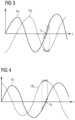
- Figure 3 shows the time course of the potential generated at the output end face 10 of the first piezoelectric transformer 1 and of the potential generated at the output end face 110 of the second piezoelectric transformer 101.
- the curve U 1 shows the time course of the potential generated at the output end face 10 of the first piezoelectric transformer 1 and the curve U 2 shows the time course of the potential generated at the output end face 110 of the second piezoelectric transformer 101.
- the input voltage applied to the second piezoelectric transformer 101 is phase-shifted by +90° with respect to the input voltage applied to the first piezoelectric transformer 1.
- Plasma and ozone can be generated by the piezoelectric transformer 1 through a dielectric barrier discharge (DBD).
- DBD dielectric barrier discharge
- the plasma generation as a result of a dielectric barrier discharge largely depends on the rate of change of the potential generated at the output end face 10, 110.
- Figure 3 the potential generated on two immediately adjacent piezoelectric transformers 1, 101 are shifted by 90 ° to each other, the potentials alternately show a maximum rate of change.
- the curve U 1 has a maximum rate of increase at time t 1 .
- the curve U 2 points On the other hand, at time t 1 there is only a minimal change. Accordingly, a plasma is ignited at the first piezoelectric transformer 1 at time t 2 and no plasma is ignited at the second piezoelectric transformer 101. Since the two transformers 1, 101 always generate plasma alternately with one another, they do not interfere with each other's plasma generation.
- Figure 4 also shows the course of the potentials generated on the output end faces 10, 110 of the first and second piezoelectric transformers 1, 101, with the input voltage of the second piezoelectric transformer 101 now being phase-shifted by -90 ° compared to the input voltage of the first piezoelectric transformer 1.
- Figure 3 explained configuration, in which the two transformers 1, 101 always generate plasma alternately with one another, since they each reach a maximum in the rate of increase of the output-side potentials when the other transformer 1, 101 shows an almost constant potential.
- controlling the two transformers 1, 101 offset by 90° makes it possible to optimize both the geometric field gradient and the time profile of the rate of change of the generated fields in such a way that the amount of plasma generated by the two transformers 1, 101 can be maximized.
- Figure 5 shows a device for generating a non-thermal atmospheric pressure plasma, which, in addition to the first piezoelectric transformer 1 and the second piezoelectric transformer 101, has a third Transformer 201 and a fourth transformer 301. Furthermore, the device can have further piezoelectric transformers.
- the piezoelectric transformers 1, 101, 201, 301 are arranged parallel to one another.
- the surface normals of the output end faces of the piezoelectric transformers are parallel to one another.
- the piezoelectric transformers 1, 101, 201, 301 are arranged at a short distance from one another.
- the piezoelectric transformers 1, 101, 201, 301 can be arranged at a distance of more than 5 mm and less than 5 cm from one another.
- the piezoelectric transformers 1, 101, 201, 301 are arranged to form a line. This arrangement of piezoelectric transformers 1, 101, 201, 301 in a single line makes it possible, for example, to effectively apply plasma to films on assembly lines.
- the first transformer 1 is immediately adjacent to the second transformer 101.
- the second transformer 101 is immediately adjacent to the first transformer 1 and to the third transformer 201, etc.
- the device further has a control circuit which applies an input voltage to each of the piezoelectric transformers 1, 101, 201, 301.
- the input voltages are applied in such a way that input voltages are applied to adjacent piezoelectric transformers, which are each 90° out of phase with one another.
- control circuit could each apply an identical input voltage, i.e. input voltages that are not out of phase with each other, to the first and third piezoelectric transformers 1, 201 and each apply an input voltage to the second and fourth piezoelectric transformers 101, 301, which is phase-shifted by 90° compared to the input voltage present at the first and third transformers 1, 101.
- the input voltage of the first transformer 1 has a phase shift of 0°
- the input voltage of the second transformer 101 and the fourth transformer 301 each has a phase shift of +90°
- the input voltage of the third transformer 201 has a phase shift of +180°.
- Further possible phase shifts of the input voltages applied to the first to fourth piezoelectric transformers 1, 101, 201, 301 can be found in the table below. The phase shifts can always be seen relative to each other. Accordingly, all permutations with positive and negative signs as well as phase shifts shifted by n° are possible.
- the table lists the phase shifts of the input voltages applied to the first to fourth piezoelectric transformers 1, 101, 201, 301.
- the phase shifts can always be seen relative to each other. Accordingly, all permutations with positive and negative signs are possible. Furthermore, all shifts in which all phase shifts are shifted by an arbitrary amount n° are included.
- Figure 6 shows another embodiment of the device.
- the output end faces 10, 110 of the piezoelectric transformers 1, 101, 201, 301 of the device are shown in a top view.
- the piezoelectric transformers are arranged parallel to each other and form an array 1, 101, 201, 301 which has several rows and several columns.
- the first and third transformers 1, 201 are arranged in a row.
- the first and second transformers 1, 101 are arranged in a column.
- the first and fourth transformers 1, 301 are arranged along the same diagonal.
- the second and third transformers 101, 201 are also arranged along the same diagonal.
- the transformers 1, 101, 201, 301 are controlled in such a way that piezoelectric transformers 1, 101 that are immediately adjacent to one another are each supplied with an input voltage that is 90° out of phase with one another.
- the piezoelectric transformers 1, 301 and 101, 201, which lie on a diagonal, are each supplied with an input voltage that is not out of phase with one another. This can prevent the ignition of plasma along the diagonal.
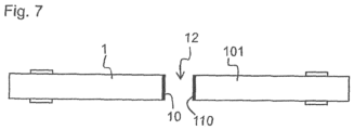
- Figure 7 shows a further exemplary embodiment of a device for generating a non-thermal atmospheric pressure plasma.
- the first piezoelectric transformer 1 and the second piezoelectric transformer 101 are arranged opposite one another.
- the output-side end face 10 of the first piezoelectric transformer 1 points towards the output-side end face 110 of the second piezoelectric transformer 101.
- the two piezoelectric transformers 1, 101 are supplied with an input voltage by a control circuit in such a way that the input voltage applied to the first piezoelectric transformer 1 is phase-shifted by 90° compared to the input voltage applied to the second piezoelectric transformer 101.
- the device shown is particularly suitable for treating two sides of a film with plasma at the same time.
- the film can be formed by a between the two output end faces 10, 110 of the piezoelectric transformers 1, 101 Space 12 can be passed through.
- An upper side of the film can face the first piezoelectric transformer 1 and an underside of the film can face the second piezoelectric transformer 101.
- the first piezoelectric transformer 1 generates a plasma to treat the top of the film
- the second piezoelectric transformer 101 generates a plasma to treat the bottom of the film with plasma.
- a first group of piezoelectric transformers can form either a row or an array and can be arranged opposite a second group of piezoelectric transformers, which also form a row or an array.
- the transformers are supplied with an input voltage, whereby it should be noted that transformers immediately adjacent to one another should each be supplied with an input voltage that is offset by 90° to one another and that transformers located opposite one another should also be supplied with an input voltage that is offset by 90° to one another and that the transformers, which are arranged on a diagonal, are each supplied with in-phase input voltages.
Landscapes
- Physics & Mathematics (AREA)
- Engineering & Computer Science (AREA)
- Plasma & Fusion (AREA)
- Acoustics & Sound (AREA)
- Spectroscopy & Molecular Physics (AREA)
- Power Engineering (AREA)
- Plasma Technology (AREA)
Applications Claiming Priority (2)
| Application Number | Priority Date | Filing Date | Title |
|---|---|---|---|
| DE102016104490.3A DE102016104490B3 (de) | 2016-03-11 | 2016-03-11 | Vorrichtung und Verfahren zur Erzeugung eines nichtthermischen Atmosphärendruck-Plasmas |
| PCT/EP2017/051559 WO2017153084A1 (de) | 2016-03-11 | 2017-01-25 | Vorrichtung und verfahren zur erzeugung eines nichtthermischen atmosphärendruck-plasmas |
Publications (2)
| Publication Number | Publication Date |
|---|---|
| EP3427552A1 EP3427552A1 (de) | 2019-01-16 |
| EP3427552B1 true EP3427552B1 (de) | 2024-03-06 |
Family
ID=57906618
Family Applications (1)
| Application Number | Title | Priority Date | Filing Date |
|---|---|---|---|
| EP17701690.4A Active EP3427552B1 (de) | 2016-03-11 | 2017-01-25 | Vorrichtung und verfahren zur erzeugung eines nichtthermischen atmosphärendruck-plasmas |
Country Status (7)
| Country | Link |
|---|---|
| US (1) | US11076475B2 (ko) |
| EP (1) | EP3427552B1 (ko) |
| JP (1) | JP6600834B2 (ko) |
| KR (1) | KR102183551B1 (ko) |
| CN (1) | CN108702837B (ko) |
| DE (1) | DE102016104490B3 (ko) |
| WO (1) | WO2017153084A1 (ko) |
Families Citing this family (3)
| Publication number | Priority date | Publication date | Assignee | Title |
|---|---|---|---|---|
| DE102017105401B4 (de) * | 2017-03-14 | 2019-01-31 | Tdk Electronics Ag | Vorrichtung zur Erzeugung eines nichtthermischen Atmosphärendruck-Plasmas |
| DE102018105895A1 (de) | 2018-03-14 | 2019-09-19 | Tdk Electronics Ag | Vorrichtung zur Erzeugung eines nicht-thermischen Atmosphärendruck-Plasmas und Verfahren zum Betrieb eines piezoelektrischen Transformators |
| DE102020100828B4 (de) * | 2020-01-15 | 2023-03-09 | Tdk Electronics Ag | Vorrichtung zur Erzeugung einer dielektrischen Barriereentladung und Verfahren zur Behandlung eines zu aktivierenden Objekts |
Family Cites Families (32)
| Publication number | Priority date | Publication date | Assignee | Title |
|---|---|---|---|---|
| EP0831679B1 (en) * | 1995-06-05 | 2008-10-01 | Musashino Kikai Co., Ltd. | Power supply for multielectrode discharge |
| US5747914A (en) * | 1997-02-05 | 1998-05-05 | Motorola Inc. | Driving circuit for multisectional piezoelectric transformers using pulse-position-modulation/phase modulation |
| JP2001102195A (ja) * | 1999-09-29 | 2001-04-13 | Sony Corp | イオン発生装置 |
| US6476542B2 (en) * | 2000-12-20 | 2002-11-05 | Cts Corporation | Piezoelectric transformer with dual-phase input drive |
| US20040232806A1 (en) | 2003-05-16 | 2004-11-25 | Hiroshi Nakatsuka | Piezoelectric transformer, power supply circuit and lighting unit using the same |
| JP4540043B2 (ja) | 2004-04-05 | 2010-09-08 | 一雄 岡野 | コロナ放電型イオナイザ |
| IES20050301A2 (en) | 2005-05-11 | 2006-11-15 | Univ Dublin City | Plasma source |
| DE102005032890B4 (de) | 2005-07-14 | 2009-01-29 | Je Plasmaconsult Gmbh | Vorrichtung zur Erzeugung von Atmosphärendruck-Plasmen |
| US7755254B2 (en) * | 2006-12-04 | 2010-07-13 | Ngk Insulators, Ltd. | Honeycomb-type piezoelectric/electrostrictive element |
| JP5064085B2 (ja) | 2007-04-06 | 2012-10-31 | 富山県 | プラズマ処理装置 |
| JP5201958B2 (ja) | 2007-11-22 | 2013-06-05 | 国立大学法人東京工業大学 | 圧電トランス電極を用いたイオナイザ及びそれによる除電用イオン発生方法 |
| DE102008018827B4 (de) * | 2008-04-15 | 2010-05-12 | Maschinenfabrik Reinhausen Gmbh | Vorrichtung zur Erzeugung eines Atmosphärendruck-Plasmas |
| DE202008008980U1 (de) * | 2008-07-04 | 2008-09-04 | Maschinenfabrik Reinhausen Gmbh | Vorrichtung zur Erzeugung eines Atmosphärendruck-Plasmas |
| US8689537B1 (en) * | 2008-10-20 | 2014-04-08 | Cu Aerospace, Llc | Micro-cavity discharge thruster (MCDT) |
| JP5052537B2 (ja) | 2009-01-27 | 2012-10-17 | 三井造船株式会社 | プラズマ生成装置およびプラズマ生成方法 |
| KR20110134217A (ko) | 2010-06-08 | 2011-12-14 | 다이나믹솔라디자인 주식회사 | 다중 분할 전극 세트를 위한 급전장치를 구비한 플라즈마 챔버 |
| EP2779803B1 (en) * | 2011-11-11 | 2020-01-08 | Saga University | Plasma generation device for suppressing localised discharges |
| DE102012103938A1 (de) * | 2012-05-04 | 2013-11-07 | Reinhausen Plasma Gmbh | Plasmamodul für eine Plasmaerzeugungsvorrichtung und Plasmaerzeugungsvorrichtung |
| US8896211B2 (en) * | 2013-01-16 | 2014-11-25 | Orteron (T.O) Ltd | Physical means and methods for inducing regenerative effects on living tissues and fluids |
| DE102013100617B4 (de) * | 2013-01-22 | 2016-08-25 | Epcos Ag | Vorrichtung zur Erzeugung eines Plasmas und Handgerät mit der Vorrichtung |
| DE102013107448B4 (de) * | 2013-07-15 | 2016-11-24 | Relyon Plasma Gmbh | Anordnung zur Keimreduktion mittels Plasma |
| DE102013109887A1 (de) * | 2013-09-10 | 2015-03-12 | Reinhausen Plasma Gmbh | Handgerät und Verfahren zur Plasmabehandlung |
| DE102014110405A1 (de) * | 2014-07-23 | 2016-01-28 | Epcos Ag | Piezoelektrischer Transformator |
| DE102015112410A1 (de) * | 2015-07-29 | 2017-02-02 | Epcos Ag | Verfahren zur Frequenzregelung eines piezoelektrischen Transformators sowie Schaltungsanordnung mit einem piezoelektrischen Transformator |
| DE102015113656A1 (de) * | 2015-08-18 | 2017-02-23 | Epcos Ag | Plasmagenerator und Verfahren zur Einstellung eines Ionenverhältnisses |
| DE102015117106A1 (de) * | 2015-10-07 | 2017-04-13 | Epcos Ag | Piezoelektrischer Transformator |
| DE102015120160B4 (de) * | 2015-11-20 | 2023-02-23 | Tdk Electronics Ag | Piezoelektrischer Transformator |
| DE102016102488A1 (de) * | 2016-02-12 | 2017-08-17 | Epcos Ag | Verfahren zur Herstellung eines piezoelektrischen Transformators und piezoelektrischer Transformator |
| DE102016104104A1 (de) * | 2016-03-07 | 2017-09-07 | Epcos Ag | Verfahren zur Herstellung von Ozon und Vorrichtung zur Ozongenerierung |
| DE102017105401B4 (de) * | 2017-03-14 | 2019-01-31 | Tdk Electronics Ag | Vorrichtung zur Erzeugung eines nichtthermischen Atmosphärendruck-Plasmas |
| DE102017105410A1 (de) * | 2017-03-14 | 2018-09-20 | Epcos Ag | Plasmagenerator |
| DE102017105415B4 (de) * | 2017-03-14 | 2018-10-11 | Epcos Ag | Vorrichtung zur Erzeugung eines nicht-thermischen Atmosphärendruck-Plasmas und Verfahren zur Frequenzregelung eines piezoelektrischen Transformators |
-
2016
- 2016-03-11 DE DE102016104490.3A patent/DE102016104490B3/de active Active
-
2017
- 2017-01-25 US US16/084,192 patent/US11076475B2/en active Active
- 2017-01-25 WO PCT/EP2017/051559 patent/WO2017153084A1/de active Application Filing
- 2017-01-25 KR KR1020187026813A patent/KR102183551B1/ko active IP Right Grant
- 2017-01-25 JP JP2018545585A patent/JP6600834B2/ja active Active
- 2017-01-25 EP EP17701690.4A patent/EP3427552B1/de active Active
- 2017-01-25 CN CN201780016583.9A patent/CN108702837B/zh active Active
Also Published As
| Publication number | Publication date |
|---|---|
| JP6600834B2 (ja) | 2019-11-06 |
| KR20180116329A (ko) | 2018-10-24 |
| DE102016104490B3 (de) | 2017-05-24 |
| KR102183551B1 (ko) | 2020-11-27 |
| US20200187343A1 (en) | 2020-06-11 |
| US11076475B2 (en) | 2021-07-27 |
| CN108702837A (zh) | 2018-10-23 |
| CN108702837B (zh) | 2021-05-18 |
| EP3427552A1 (de) | 2019-01-16 |
| JP2019507943A (ja) | 2019-03-22 |
| WO2017153084A1 (de) | 2017-09-14 |
Similar Documents
| Publication | Publication Date | Title |
|---|---|---|
| EP3172772B1 (de) | Piezoelektrischer transformator | |
| DE69834020T2 (de) | Kapazitiv gekoppelter rf plasmareaktor und verfahren zur herstellung von werkstücken | |
| DE69302029T2 (de) | Induktiven Radiofrequenz-Plasma-Bearbeitungssystem mit einer Spule zur Erzeugung eines gleichmässigen Feldes | |
| EP1287548B1 (de) | Plasmaätzanlage | |
| EP3427552B1 (de) | Vorrichtung und verfahren zur erzeugung eines nichtthermischen atmosphärendruck-plasmas | |
| EP3365928B1 (de) | Vorrichtung zur erzeugung eines atmosphärendruck-plasmas | |
| DE3309709A1 (de) | Gebilde von einrichtungen fuer akustische wellen | |
| DE69629885T2 (de) | Magnetfeldgenerator für Magnetronplasma | |
| EP3375019A1 (de) | Piezoelektrischer transformator | |
| EP3766107B1 (de) | Vorrichtung zur erzeugung eines nicht-thermischen atmosphärendruck-plasmas und verfahren zum betrieb eines piezoelektrischen transformators | |
| DE102015014903A1 (de) | Waferboot und Plasma-Behandlungsvorrichtung für Wafer | |
| DE60001883T2 (de) | Elektroden einer Korona-Vorionisierungsvorrichtung für Gaslaser | |
| EP3378108B1 (de) | Piezoelektrischer transformator | |
| EP1776725B1 (de) | Piezoelektrischer transformator | |
| DE102015117106A1 (de) | Piezoelektrischer Transformator | |
| DE102016110216B4 (de) | Verfahren zur Herstellung einer Vielzahl von piezoelektrischen Vielschichtbauelementen | |
| WO2017137195A1 (de) | Verfahren zur herstellung eines piezoelektrischen transformators und piezoelektrischer transformator | |
| DE102015017460B4 (de) | Piezoelektrischer Transformator | |
| LU84372A1 (de) | Vorrichtung zur erzeugung eines laseraktiven zustandes in einer schnellen unterschallstroemung | |
| WO2011157424A1 (de) | Vorrichtung zur kontinuierlichen plasmabehandlung und/oder plasmabeschichtung eines materialstücks | |
| DE602004012595T2 (de) | Gas-port-baugruppe | |
| DE102010043940A1 (de) | Mikrowellen-ICP-Resonator | |
| EP3367419B1 (de) | Elektrodeneinheit mit einem internen elektrischen netzwerk zur zuführung von hochfrequenter spannung und trägeranordnung für eine plasmabehandlungsanlage | |
| DE69201669T2 (de) | Hochspannungs-Isoliervorrichtung. | |
| DD295061B5 (de) | Schaltungsanordnung fuer Plasmareaktoren |
Legal Events
| Date | Code | Title | Description |
|---|---|---|---|
| STAA | Information on the status of an ep patent application or granted ep patent |
Free format text: STATUS: UNKNOWN |
|
| STAA | Information on the status of an ep patent application or granted ep patent |
Free format text: STATUS: THE INTERNATIONAL PUBLICATION HAS BEEN MADE |
|
| PUAI | Public reference made under article 153(3) epc to a published international application that has entered the european phase |
Free format text: ORIGINAL CODE: 0009012 |
|
| STAA | Information on the status of an ep patent application or granted ep patent |
Free format text: STATUS: REQUEST FOR EXAMINATION WAS MADE |
|
| 17P | Request for examination filed |
Effective date: 20180823 |
|
| AK | Designated contracting states |
Kind code of ref document: A1 Designated state(s): AL AT BE BG CH CY CZ DE DK EE ES FI FR GB GR HR HU IE IS IT LI LT LU LV MC MK MT NL NO PL PT RO RS SE SI SK SM TR |
|
| AX | Request for extension of the european patent |
Extension state: BA ME |
|
| STAA | Information on the status of an ep patent application or granted ep patent |
Free format text: STATUS: REQUEST FOR EXAMINATION WAS MADE |
|
| DAV | Request for validation of the european patent (deleted) | ||
| DAX | Request for extension of the european patent (deleted) | ||
| STAA | Information on the status of an ep patent application or granted ep patent |
Free format text: STATUS: EXAMINATION IS IN PROGRESS |
|
| 17Q | First examination report despatched |
Effective date: 20210414 |
|
| STAA | Information on the status of an ep patent application or granted ep patent |
Free format text: STATUS: EXAMINATION IS IN PROGRESS |
|
| REG | Reference to a national code |
Ref country code: DE Ref legal event code: R079 Ref document number: 502017015897 Country of ref document: DE Free format text: PREVIOUS MAIN CLASS: H05H0001240000 Ipc: H10N0030800000 Ref country code: DE Ref legal event code: R079 Free format text: PREVIOUS MAIN CLASS: H05H0001240000 Ipc: H10N0030800000 |
|
| GRAP | Despatch of communication of intention to grant a patent |
Free format text: ORIGINAL CODE: EPIDOSNIGR1 |
|
| STAA | Information on the status of an ep patent application or granted ep patent |
Free format text: STATUS: GRANT OF PATENT IS INTENDED |
|
| RIC1 | Information provided on ipc code assigned before grant |
Ipc: H10N 30/80 20230101AFI20231023BHEP |
|
| INTG | Intention to grant announced |
Effective date: 20231113 |
|
| GRAS | Grant fee paid |
Free format text: ORIGINAL CODE: EPIDOSNIGR3 |
|
| GRAA | (expected) grant |
Free format text: ORIGINAL CODE: 0009210 |
|
| STAA | Information on the status of an ep patent application or granted ep patent |
Free format text: STATUS: THE PATENT HAS BEEN GRANTED |
|
| AK | Designated contracting states |
Kind code of ref document: B1 Designated state(s): AL AT BE BG CH CY CZ DE DK EE ES FI FR GB GR HR HU IE IS IT LI LT LU LV MC MK MT NL NO PL PT RO RS SE SI SK SM TR |
|
| REG | Reference to a national code |
Ref country code: GB Ref legal event code: FG4D Free format text: NOT ENGLISH |
|
| REG | Reference to a national code |
Ref country code: CH Ref legal event code: EP |
|
| REG | Reference to a national code |
Ref country code: DE Ref legal event code: R096 Ref document number: 502017015897 Country of ref document: DE |
|
| REG | Reference to a national code |
Ref country code: IE Ref legal event code: FG4D Free format text: LANGUAGE OF EP DOCUMENT: GERMAN |
|
| REG | Reference to a national code |
Ref country code: LT Ref legal event code: MG9D |
|
| PG25 | Lapsed in a contracting state [announced via postgrant information from national office to epo] |
Ref country code: LT Free format text: LAPSE BECAUSE OF FAILURE TO SUBMIT A TRANSLATION OF THE DESCRIPTION OR TO PAY THE FEE WITHIN THE PRESCRIBED TIME-LIMIT Effective date: 20240306 |
|
| REG | Reference to a national code |
Ref country code: NL Ref legal event code: MP Effective date: 20240306 |
|
| PG25 | Lapsed in a contracting state [announced via postgrant information from national office to epo] |
Ref country code: GR Free format text: LAPSE BECAUSE OF FAILURE TO SUBMIT A TRANSLATION OF THE DESCRIPTION OR TO PAY THE FEE WITHIN THE PRESCRIBED TIME-LIMIT Effective date: 20240607 |
|
| PG25 | Lapsed in a contracting state [announced via postgrant information from national office to epo] |
Ref country code: RS Free format text: LAPSE BECAUSE OF FAILURE TO SUBMIT A TRANSLATION OF THE DESCRIPTION OR TO PAY THE FEE WITHIN THE PRESCRIBED TIME-LIMIT Effective date: 20240606 Ref country code: HR Free format text: LAPSE BECAUSE OF FAILURE TO SUBMIT A TRANSLATION OF THE DESCRIPTION OR TO PAY THE FEE WITHIN THE PRESCRIBED TIME-LIMIT Effective date: 20240306 |
|
| PG25 | Lapsed in a contracting state [announced via postgrant information from national office to epo] |
Ref country code: ES Free format text: LAPSE BECAUSE OF FAILURE TO SUBMIT A TRANSLATION OF THE DESCRIPTION OR TO PAY THE FEE WITHIN THE PRESCRIBED TIME-LIMIT Effective date: 20240306 |
|
| PG25 | Lapsed in a contracting state [announced via postgrant information from national office to epo] |
Ref country code: RS Free format text: LAPSE BECAUSE OF FAILURE TO SUBMIT A TRANSLATION OF THE DESCRIPTION OR TO PAY THE FEE WITHIN THE PRESCRIBED TIME-LIMIT Effective date: 20240606 Ref country code: NO Free format text: LAPSE BECAUSE OF FAILURE TO SUBMIT A TRANSLATION OF THE DESCRIPTION OR TO PAY THE FEE WITHIN THE PRESCRIBED TIME-LIMIT Effective date: 20240606 Ref country code: LT Free format text: LAPSE BECAUSE OF FAILURE TO SUBMIT A TRANSLATION OF THE DESCRIPTION OR TO PAY THE FEE WITHIN THE PRESCRIBED TIME-LIMIT Effective date: 20240306 Ref country code: HR Free format text: LAPSE BECAUSE OF FAILURE TO SUBMIT A TRANSLATION OF THE DESCRIPTION OR TO PAY THE FEE WITHIN THE PRESCRIBED TIME-LIMIT Effective date: 20240306 Ref country code: GR Free format text: LAPSE BECAUSE OF FAILURE TO SUBMIT A TRANSLATION OF THE DESCRIPTION OR TO PAY THE FEE WITHIN THE PRESCRIBED TIME-LIMIT Effective date: 20240607 Ref country code: FI Free format text: LAPSE BECAUSE OF FAILURE TO SUBMIT A TRANSLATION OF THE DESCRIPTION OR TO PAY THE FEE WITHIN THE PRESCRIBED TIME-LIMIT Effective date: 20240306 Ref country code: ES Free format text: LAPSE BECAUSE OF FAILURE TO SUBMIT A TRANSLATION OF THE DESCRIPTION OR TO PAY THE FEE WITHIN THE PRESCRIBED TIME-LIMIT Effective date: 20240306 Ref country code: BG Free format text: LAPSE BECAUSE OF FAILURE TO SUBMIT A TRANSLATION OF THE DESCRIPTION OR TO PAY THE FEE WITHIN THE PRESCRIBED TIME-LIMIT Effective date: 20240306 |
|
| PG25 | Lapsed in a contracting state [announced via postgrant information from national office to epo] |
Ref country code: SE Free format text: LAPSE BECAUSE OF FAILURE TO SUBMIT A TRANSLATION OF THE DESCRIPTION OR TO PAY THE FEE WITHIN THE PRESCRIBED TIME-LIMIT Effective date: 20240306 Ref country code: LV Free format text: LAPSE BECAUSE OF FAILURE TO SUBMIT A TRANSLATION OF THE DESCRIPTION OR TO PAY THE FEE WITHIN THE PRESCRIBED TIME-LIMIT Effective date: 20240306 |
|
| PG25 | Lapsed in a contracting state [announced via postgrant information from national office to epo] |
Ref country code: NL Free format text: LAPSE BECAUSE OF FAILURE TO SUBMIT A TRANSLATION OF THE DESCRIPTION OR TO PAY THE FEE WITHIN THE PRESCRIBED TIME-LIMIT Effective date: 20240306 |
|
| PG25 | Lapsed in a contracting state [announced via postgrant information from national office to epo] |
Ref country code: NL Free format text: LAPSE BECAUSE OF FAILURE TO SUBMIT A TRANSLATION OF THE DESCRIPTION OR TO PAY THE FEE WITHIN THE PRESCRIBED TIME-LIMIT Effective date: 20240306 |