EP3427552B1 - Apparatus and method for generating a non-thermal atmospheric pressure plasma - Google Patents
Apparatus and method for generating a non-thermal atmospheric pressure plasma Download PDFInfo
- Publication number
- EP3427552B1 EP3427552B1 EP17701690.4A EP17701690A EP3427552B1 EP 3427552 B1 EP3427552 B1 EP 3427552B1 EP 17701690 A EP17701690 A EP 17701690A EP 3427552 B1 EP3427552 B1 EP 3427552B1
- Authority
- EP
- European Patent Office
- Prior art keywords
- transformers
- piezoelectric
- another
- transformer
- phase
- Prior art date
- Legal status (The legal status is an assumption and is not a legal conclusion. Google has not performed a legal analysis and makes no representation as to the accuracy of the status listed.)
- Active
Links
Images


Classifications
-
- H—ELECTRICITY
- H05—ELECTRIC TECHNIQUES NOT OTHERWISE PROVIDED FOR
- H05H—PLASMA TECHNIQUE; PRODUCTION OF ACCELERATED ELECTRICALLY-CHARGED PARTICLES OR OF NEUTRONS; PRODUCTION OR ACCELERATION OF NEUTRAL MOLECULAR OR ATOMIC BEAMS
- H05H1/00—Generating plasma; Handling plasma
- H05H1/24—Generating plasma
- H05H1/2475—Generating plasma using acoustic pressure discharges
- H05H1/2481—Generating plasma using acoustic pressure discharges the plasma being activated using piezoelectric actuators
-
- H—ELECTRICITY
- H10—SEMICONDUCTOR DEVICES; ELECTRIC SOLID-STATE DEVICES NOT OTHERWISE PROVIDED FOR
- H10N—ELECTRIC SOLID-STATE DEVICES NOT OTHERWISE PROVIDED FOR
- H10N30/00—Piezoelectric or electrostrictive devices
- H10N30/40—Piezoelectric or electrostrictive devices with electrical input and electrical output, e.g. functioning as transformers
-
- H—ELECTRICITY
- H10—SEMICONDUCTOR DEVICES; ELECTRIC SOLID-STATE DEVICES NOT OTHERWISE PROVIDED FOR
- H10N—ELECTRIC SOLID-STATE DEVICES NOT OTHERWISE PROVIDED FOR
- H10N30/00—Piezoelectric or electrostrictive devices
- H10N30/80—Constructional details
- H10N30/802—Circuitry or processes for operating piezoelectric or electrostrictive devices not otherwise provided for, e.g. drive circuits
- H10N30/804—Circuitry or processes for operating piezoelectric or electrostrictive devices not otherwise provided for, e.g. drive circuits for piezoelectric transformers
Definitions
- the present invention relates to a device for generating a non-thermal atmospheric pressure plasma and a method for generating plasma.
- the device in particular has a first and a second piezoelectric transformer, on the output side of which a high potential is generated, which can be used to ionize a process gas.
- the volume on which the plasma generated by a piezoelectric transformer can act is, in principle, limited to an area in front of the output side of the piezoelectric transformer. Particularly in industrial applications, it is often necessary to process a larger area. Accordingly, several piezoelectric transformers should be used for this, which should be arranged as close together as possible without the transformers interfering with each other.
- US 2002/074903 A1 shows a piezoelectric transformer of the Rosen type, the input area of which is divided into two sections is divided. A first input voltage can be applied to the electrodes of the first subregion and a second input voltage can be applied to the electrodes of the second subregion. Furthermore, the transformer has a single common output area for the two sub-areas of the input area.
- the object of the present invention is now to provide an improved device for generating a non-thermal Specify atmospheric pressure plasma, which in particular makes it possible to arrange several piezoelectric transformers at a short distance from one another without the transformers interfering with one another. Another object is to provide an improved method for generating non-thermal atmospheric pressure plasma.
- a device for generating a non-thermal atmospheric pressure plasma which has a first piezoelectric transformer, a second piezoelectric transformer and a drive circuit.
- the drive circuit is designed to apply an input voltage to each of the piezoelectric transformers, the input voltage applied to the first transformer being 90° out of phase with the input voltage applied to the second transformer.
- phase shift is always given in relative terms. Accordingly, the indication of a phase shift of 90° can be viewed as the amount of the phase shift, unless a positive phase shift of +90° or a negative phase shift of -90° is explicitly stated.
- the two piezoelectric transformers are operated with an input voltage shifted by 90° to one another, plasma generation always takes place alternately first piezoelectric transformer and the second piezoelectric transformer. In this way, it can be avoided that the two transformers generate plasma at the same time, which would cause the two plasma generations to interfere with each other. By alternately generating the plasma with the first and second transformers, an overall improved plasma generation rate can be achieved.
- the first and second piezoelectric transformers may be arranged at a distance of less than 5 cm from each other.
- the small distance between the transformers is made possible by the fact that the two transformers do not interfere with each other during plasma generation.
- the two transformers should be at least 5 mm apart from each other.
- the control circuit can be designed in such a way that the input voltages that are applied to the piezoelectric transformers each have the same frequency. Otherwise, the input voltages would diverge due to a different frequency, so that a phase shift of 90° could not be maintained in continuous operation. In addition, in this case there would be a beat and corresponding beat effects. Because the transformers are controlled with the same frequency, the formation of a beat can be avoided.
- the transformers can be trimmed to the same length and thus the same resonance frequency using a grinding process.
- a frequency can be selected to control the transformers the average of the resonance frequencies of the piezoelectric transformers of the device.
- the device can also have further piezoelectric transformers, wherein the control circuit can be designed to apply the input voltages to the transformers in such a way that input voltages that are present on transformers immediately adjacent to one another are each 90 ° out of phase with one another.
- the piezoelectric transformers can be arranged in parallel to each other and form a single line.
- the piezoelectric transformers can be arranged parallel to one another and form an array with at least two rows and at least two columns.
- the control circuit can be designed to apply the input voltages to the transformers in such a way that the input voltages present at the transformers, which are arranged on one and the same diagonal of the array, are each 0° out of phase with one another.
- the first and second piezoelectric transformers can be arranged such that their output end faces lie opposite one another.
- An object to be processed for example a film, can pass through a gap which is formed between the output end faces of the two transformers. Accordingly, two opposing surfaces of the object can be exposed to plasma generated by the device at the same time.
- the device may have a first group of piezoelectric transformers, which comprises the first piezoelectric transformer and further piezoelectric transformers, which are arranged parallel to one another and form a single row, and a second group of piezoelectric transformers, which comprises the second piezoelectric transformer and others has piezoelectric transformers which are arranged parallel to one another and form a single line.
- the first group of piezoelectric transformers and the second group of piezoelectric transformers can be arranged opposite one another, with the control circuit being designed to apply the input voltages to the transformers of a row in such a way that input voltages that are present on transformers immediately adjacent to one another are in each case by are 90 ° out of phase with each other, and that furthermore the input voltages that are present at transformers opposite each other are each 90 ° out of phase with each other.
- the device can have a first group of piezoelectric transformers, which has the first piezoelectric transformer and further piezoelectric transformers, which are arranged parallel to one another and form an array with at least two columns and at least two rows, and a second Group of piezoelectric transformers, comprising the second piezoelectric transformer and further piezoelectric transformers, which are arranged parallel to one another and form an array with at least two columns and at least two rows.
- the first group of piezoelectric transformers and the second group of piezoelectric transformers can be arranged opposite one another, with the control circuit being designed to apply the input voltages to the transformers in such a way that input voltages that are present on transformers immediately adjacent to one another are each rotated by 90° are phase-shifted from one another, that the input voltages that are present at the transformers that are arranged on one and the same diagonal of the array are each 0° out of phase with one another, and that furthermore the input voltages that are present at transformers opposite one another are each 90° out of phase are out of phase with each other.
- the present invention relates to a method for generating a non-thermal atmospheric pressure plasma by means of at least a first piezoelectric transformer and a second piezoelectric transformer, wherein an input voltage which is relative to one another is applied to the first piezoelectric transformer and to the second piezoelectric transformer 90° out of phase.
- the method can be carried out in particular with the device described above. Accordingly, any functional and structural feature that is related was disclosed with the device also apply to the method.
- Figure 1 shows a piezoelectric transformer 1 in a perspective view.
- the piezoelectric transformer 1 can be used in particular in a device Generation of non-thermal atmospheric pressure plasma can be used.
- a piezoelectric transformer 1 is a type of resonance transformer which is based on piezoelectricity and, in contrast to conventional magnetic transformers, represents an electromechanical system.
- the piezoelectric transformer 1 is, for example, a Rosen type transformer.
- the piezoelectric transformer 1 has an input region 2 and an output region 3, with the output region 3 adjoining the input region 2 in a longitudinal direction z.
- the piezoelectric transformer 1 has electrodes 4 to which an alternating voltage can be applied.
- the electrodes 4 extend in the longitudinal direction z of the piezoelectric transformer 1.
- the electrodes 4 are alternately stacked with a piezoelectric material 5 in a stacking direction x that is perpendicular to the longitudinal direction z.
- the piezoelectric material 5 is polarized in the stacking direction x.
- the electrodes 4 are arranged inside the piezoelectric transformer 1 and are also referred to as internal electrodes.
- the piezoelectric transformer 1 has a first side surface 6 and a second side surface 7, which is opposite the first side surface 6.
- a first external electrode 8 is arranged on the first side surface 6.
- a second external electrode (not shown) is arranged on the second side surface 7.
- the internal electrodes 4 alternate in the stacking direction x with either the first External electrode 8 or the second external electrode is electrically contacted.
- the piezoelectric transformer 1 has a third side surface 20 and a fourth side surface 21, which face each other and which are arranged perpendicular to the first side surface 6 and the second side surface 7.
- the surface normals of the third and fourth side surfaces 20, 21 each point in the stacking direction x.
- the input area 2 can be controlled with a low alternating voltage that is applied between the electrodes 4. Due to the piezoelectric effect, the alternating voltage applied on the input side is first converted into a mechanical vibration. The frequency of the mechanical vibration is essentially dependent on the geometry and mechanical structure of the piezoelectric transformer 1.
- the output area 3 has piezoelectric material 9 and is free of internal electrodes.
- the piezoelectric material 9 in the output region is polarized in the longitudinal direction z.
- the piezoelectric material 9 of the output region 3 can be the same material as the piezoelectric material 5 of the input region 2, whereby the piezoelectric materials 5 and 9 can differ in their polarization direction.
- the piezoelectric material 9 is formed into a single monolithic layer which is completely polarized in the longitudinal direction z.
- the piezoelectric material 9 in the output region 3 only has a single polarization direction.
- an alternating voltage is applied to the electrodes 4 in the input area 2, a mechanical wave is formed within the piezoelectric material 5, 9, which generates an output voltage in the output area 3 due to the piezoelectric effect.
- the output area 3 has an output end face 10.
- an electrical voltage is thus generated between the end face 10 and the end of the electrodes 4 of the input area 2.
- a high voltage is generated at the output end face 10.
- a high potential difference also arises between the output end face and an environment of the piezoelectric transformer, which is sufficient to generate a strong electric field that ionizes a process gas.
- the piezoelectric transformer 1 generates high electric fields that are capable of ionizing gases or liquids through electrical excitation. Atoms or molecules of the respective gas or liquid are ionized and form a plasma. Ionization always occurs when the electric field strength on the surface of the piezoelectric transformer 1 exceeds the ignition field strength of the plasma.
- the ignition field strength of a plasma is the field strength that is required to ionize the atoms or molecules.
- the Figures 2A to 2C show schematically the generation of plasma by means of a device which has a first piezoelectric transformer 1 and a second piezoelectric transformer 101. Furthermore, the device has a Control circuit, which makes it possible to apply an input voltage to each of the two transformers 1, 101.
- the first transformer 1 and the second transformer 101 are arranged parallel to each other.
- the output region 3 of the first transformer 1 is arranged immediately adjacent to an output region 103 of the second transformer 101.
- the surface normals of the output end face 10 of the first transformer and an output end face 110 of the second transformer 101 are parallel to one another. There is a gap 11 between the first transformer 1 and the second transformer 101.
- piezoelectric transformers 1, 101 in a device for generating a non-thermal atmospheric pressure plasma makes it possible to simultaneously process a larger area with a plasma. Particularly in industrial applications, it is essential for efficient process design that large areas can be exposed to non-thermal atmospheric pressure plasma in a short processing time.
- Figure 2A shows an arrangement not according to the invention, in which an input voltage is applied to the two transformers 1, 101, the input voltage applied to the first transformer 1 and the input voltage applied to the second transformer 101 not being out of phase with one another.
- a sinusoidal input voltage is applied to each of the two transformers 1, 101. Accordingly, the time course of the output end faces 10 110 also has a sinusoidal curve, with a maximum potential being generated at both transformers 1, 101 at the same time.
- Figure 2A considers the potential curve at a point in time at which a maximum potential is generated on both transformers 1, 101 on the respective output end face 10, 110.
- the result is a potential curve in which the potential in the gap 11 between the two transformers 1, 101 remains approximately constant.
- a high field gradient occurs at the edges of the output end faces 10, 110, which point away from the gap 11.
- the dashed equipotential lines are close to each other.
- a high field gradient is required to ignite a plasma. Accordingly, when the two piezoelectric transformers 1, 101 are controlled in the same phase during plasma generation, the following picture results: In the area of the gap 11 between the two transformers 1, 101, no plasma is ignited due to the leveling of the potential. Plasma ignition only occurs at the edges of the output end faces 10, 110, which point away from the gap 11, since only here is there a sufficiently high field gradient.
- the amount of plasma that can be generated with this control of the piezoelectric transformers 1, 101 is not significantly higher than the amount of plasma that can be achieved with a single piezoelectric transformer 1.
- Figure 2B shows a further non-inventive control of the two piezoelectric transformers 1, 101.
- a sinusoidal input voltage is applied to each of the two piezoelectric transformers 1, 101, which are 180 ° out of phase with each other.
- a high field gradient occurs, particularly in the gap 11 between the two piezoelectric transformers 1, 101. Accordingly, a plasma ignition occurs at the first piezoelectric transformer 1, in which a plasma jet is generated which is strongly directed towards the second piezoelectric transformer 101. In the second piezoelectric transformer 101, a plasma ignition occurs, in which a plasma jet is generated which is strongly directed towards the first piezoelectric transformer 1.
- the amount of plasma produced in this case is not significantly higher than that in the same time with one single piezoelectric transformer 1 amount of plasma that can be generated.
- FIG. 2C Now consider a control in which an input voltage is applied to the first piezoelectric transformer 1, which is 90 ° out of phase with respect to an input voltage which is applied to the second piezoelectric transformer 101.
- the two input voltages each have a sinusoidal curve.
- the potential generated at the output end face 10 of the first piezoelectric transformer 1 reaches its maximum when the second piezoelectric transformer 101 is virtually field-free. Accordingly, the plasma generation by the first piezoelectric transformer 1 is not significantly influenced by the second piezoelectric transformer 101.
- the potential generated at the output end face 110 of the second piezoelectric transformer 101 reaches a maximum when the first piezoelectric transformer 1 is virtually field-free. Accordingly, the plasma generation by the second piezoelectric transformer 101 is not significantly influenced by the first piezoelectric transformer 1.
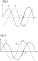
- Figure 3 shows the time course of the potential generated at the output end face 10 of the first piezoelectric transformer 1 and of the potential generated at the output end face 110 of the second piezoelectric transformer 101.
- the curve U 1 shows the time course of the potential generated at the output end face 10 of the first piezoelectric transformer 1 and the curve U 2 shows the time course of the potential generated at the output end face 110 of the second piezoelectric transformer 101.
- the input voltage applied to the second piezoelectric transformer 101 is phase-shifted by +90° with respect to the input voltage applied to the first piezoelectric transformer 1.
- Plasma and ozone can be generated by the piezoelectric transformer 1 through a dielectric barrier discharge (DBD).
- DBD dielectric barrier discharge
- the plasma generation as a result of a dielectric barrier discharge largely depends on the rate of change of the potential generated at the output end face 10, 110.
- Figure 3 the potential generated on two immediately adjacent piezoelectric transformers 1, 101 are shifted by 90 ° to each other, the potentials alternately show a maximum rate of change.
- the curve U 1 has a maximum rate of increase at time t 1 .
- the curve U 2 points On the other hand, at time t 1 there is only a minimal change. Accordingly, a plasma is ignited at the first piezoelectric transformer 1 at time t 2 and no plasma is ignited at the second piezoelectric transformer 101. Since the two transformers 1, 101 always generate plasma alternately with one another, they do not interfere with each other's plasma generation.
- Figure 4 also shows the course of the potentials generated on the output end faces 10, 110 of the first and second piezoelectric transformers 1, 101, with the input voltage of the second piezoelectric transformer 101 now being phase-shifted by -90 ° compared to the input voltage of the first piezoelectric transformer 1.
- Figure 3 explained configuration, in which the two transformers 1, 101 always generate plasma alternately with one another, since they each reach a maximum in the rate of increase of the output-side potentials when the other transformer 1, 101 shows an almost constant potential.
- controlling the two transformers 1, 101 offset by 90° makes it possible to optimize both the geometric field gradient and the time profile of the rate of change of the generated fields in such a way that the amount of plasma generated by the two transformers 1, 101 can be maximized.
- Figure 5 shows a device for generating a non-thermal atmospheric pressure plasma, which, in addition to the first piezoelectric transformer 1 and the second piezoelectric transformer 101, has a third Transformer 201 and a fourth transformer 301. Furthermore, the device can have further piezoelectric transformers.
- the piezoelectric transformers 1, 101, 201, 301 are arranged parallel to one another.
- the surface normals of the output end faces of the piezoelectric transformers are parallel to one another.
- the piezoelectric transformers 1, 101, 201, 301 are arranged at a short distance from one another.
- the piezoelectric transformers 1, 101, 201, 301 can be arranged at a distance of more than 5 mm and less than 5 cm from one another.
- the piezoelectric transformers 1, 101, 201, 301 are arranged to form a line. This arrangement of piezoelectric transformers 1, 101, 201, 301 in a single line makes it possible, for example, to effectively apply plasma to films on assembly lines.
- the first transformer 1 is immediately adjacent to the second transformer 101.
- the second transformer 101 is immediately adjacent to the first transformer 1 and to the third transformer 201, etc.
- the device further has a control circuit which applies an input voltage to each of the piezoelectric transformers 1, 101, 201, 301.
- the input voltages are applied in such a way that input voltages are applied to adjacent piezoelectric transformers, which are each 90° out of phase with one another.
- control circuit could each apply an identical input voltage, i.e. input voltages that are not out of phase with each other, to the first and third piezoelectric transformers 1, 201 and each apply an input voltage to the second and fourth piezoelectric transformers 101, 301, which is phase-shifted by 90° compared to the input voltage present at the first and third transformers 1, 101.
- the input voltage of the first transformer 1 has a phase shift of 0°
- the input voltage of the second transformer 101 and the fourth transformer 301 each has a phase shift of +90°
- the input voltage of the third transformer 201 has a phase shift of +180°.
- Further possible phase shifts of the input voltages applied to the first to fourth piezoelectric transformers 1, 101, 201, 301 can be found in the table below. The phase shifts can always be seen relative to each other. Accordingly, all permutations with positive and negative signs as well as phase shifts shifted by n° are possible.
- the table lists the phase shifts of the input voltages applied to the first to fourth piezoelectric transformers 1, 101, 201, 301.
- the phase shifts can always be seen relative to each other. Accordingly, all permutations with positive and negative signs are possible. Furthermore, all shifts in which all phase shifts are shifted by an arbitrary amount n° are included.
- Figure 6 shows another embodiment of the device.
- the output end faces 10, 110 of the piezoelectric transformers 1, 101, 201, 301 of the device are shown in a top view.
- the piezoelectric transformers are arranged parallel to each other and form an array 1, 101, 201, 301 which has several rows and several columns.
- the first and third transformers 1, 201 are arranged in a row.
- the first and second transformers 1, 101 are arranged in a column.
- the first and fourth transformers 1, 301 are arranged along the same diagonal.
- the second and third transformers 101, 201 are also arranged along the same diagonal.
- the transformers 1, 101, 201, 301 are controlled in such a way that piezoelectric transformers 1, 101 that are immediately adjacent to one another are each supplied with an input voltage that is 90° out of phase with one another.
- the piezoelectric transformers 1, 301 and 101, 201, which lie on a diagonal, are each supplied with an input voltage that is not out of phase with one another. This can prevent the ignition of plasma along the diagonal.
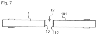
- Figure 7 shows a further exemplary embodiment of a device for generating a non-thermal atmospheric pressure plasma.
- the first piezoelectric transformer 1 and the second piezoelectric transformer 101 are arranged opposite one another.
- the output-side end face 10 of the first piezoelectric transformer 1 points towards the output-side end face 110 of the second piezoelectric transformer 101.
- the two piezoelectric transformers 1, 101 are supplied with an input voltage by a control circuit in such a way that the input voltage applied to the first piezoelectric transformer 1 is phase-shifted by 90° compared to the input voltage applied to the second piezoelectric transformer 101.
- the device shown is particularly suitable for treating two sides of a film with plasma at the same time.
- the film can be formed by a between the two output end faces 10, 110 of the piezoelectric transformers 1, 101 Space 12 can be passed through.
- An upper side of the film can face the first piezoelectric transformer 1 and an underside of the film can face the second piezoelectric transformer 101.
- the first piezoelectric transformer 1 generates a plasma to treat the top of the film
- the second piezoelectric transformer 101 generates a plasma to treat the bottom of the film with plasma.
- a first group of piezoelectric transformers can form either a row or an array and can be arranged opposite a second group of piezoelectric transformers, which also form a row or an array.
- the transformers are supplied with an input voltage, whereby it should be noted that transformers immediately adjacent to one another should each be supplied with an input voltage that is offset by 90° to one another and that transformers located opposite one another should also be supplied with an input voltage that is offset by 90° to one another and that the transformers, which are arranged on a diagonal, are each supplied with in-phase input voltages.
Landscapes
- Physics & Mathematics (AREA)
- Engineering & Computer Science (AREA)
- Plasma & Fusion (AREA)
- Acoustics & Sound (AREA)
- Spectroscopy & Molecular Physics (AREA)
- Power Engineering (AREA)
- Plasma Technology (AREA)
Description
Die vorliegende Erfindung betrifft eine Vorrichtung zur Erzeugung eines nichtthermischen Atmosphärendruck-Plasmas sowie ein Verfahren zur Plasmaerzeugung.The present invention relates to a device for generating a non-thermal atmospheric pressure plasma and a method for generating plasma.
Die Vorrichtung weist insbesondere einen ersten und einen zweiten piezoelektrischen Transformator auf, an deren Ausgangsseite ein hohes Potential erzeugt wird, das zur Ionisation eines Prozessgases genutzt werden kann. Das Volumen, auf welches das von einem piezoelektrischen Transformator erzeugte Plasma einwirken kann, ist Prinzip bedingt auf einen Bereich vor der Ausgangsseite des piezoelektrischen Transformators beschränkt. Insbesondere bei industriellen Anwendungen ist es häufig erforderlich, eine größere Fläche zu bearbeiten. Dementsprechend sollten hierfür mehrere piezoelektrische Transformatoren verwendet werden, die möglichst eng beieinander angeordnet werden sollten, ohne dass es dabei zu einer gegenseitigen Beeinträchtigung der Transformatoren kommt.The device in particular has a first and a second piezoelectric transformer, on the output side of which a high potential is generated, which can be used to ionize a process gas. The volume on which the plasma generated by a piezoelectric transformer can act is, in principle, limited to an area in front of the output side of the piezoelectric transformer. Particularly in industrial applications, it is often necessary to process a larger area. Accordingly, several piezoelectric transformers should be used for this, which should be arranged as close together as possible without the transformers interfering with each other.
Aus
Aufgabe der vorliegenden Erfindung ist es nunmehr, eine verbesserte Vorrichtung zur Erzeugung eines nichtthermischen Atmosphärendruck-Plasmas anzugeben, die es insbesondere ermöglicht, mehrere piezoelektrische Transformatoren in geringem Abstand zueinander anzuordnen, ohne dass es zu einer Beeinträchtigung der Transformatoren untereinander kommt. Eine weitere Aufgabe ist es, ein verbessertes Verfahren zur Erzeugung von nichtthermischem Atmosphärendruck-Plasma anzugeben.The object of the present invention is now to provide an improved device for generating a non-thermal Specify atmospheric pressure plasma, which in particular makes it possible to arrange several piezoelectric transformers at a short distance from one another without the transformers interfering with one another. Another object is to provide an improved method for generating non-thermal atmospheric pressure plasma.
Diese Aufgaben werden durch die Vorrichtung gemäß dem vorliegenden Anspruch 1 sowie durch das Verfahren gemäß dem zweiten unabhängigen Anspruch 12 gelöst.These tasks are achieved by the device according to the
Es wird eine Vorrichtung zur Erzeugung eines nichtthermischen Atmosphärendruck-Plasmas vorgeschlagen, die einen ersten piezoelektrischen Transformator, einen zweiten piezoelektrischen Transformator und eine Ansteuerschaltung aufweist. Die Ansteuerschaltung ist dazu ausgestaltet, an jeden der piezoelektrischen Transformatoren eine Eingangsspannung anzulegen, wobei die Eingangsspannung, die an den ersten Transformator angelegt wird, gegenüber der Eingangsspannung, die an den zweiten Transformator angelegt wird, um 90° phasenverschoben ist.A device for generating a non-thermal atmospheric pressure plasma is proposed, which has a first piezoelectric transformer, a second piezoelectric transformer and a drive circuit. The drive circuit is designed to apply an input voltage to each of the piezoelectric transformers, the input voltage applied to the first transformer being 90° out of phase with the input voltage applied to the second transformer.
Die Phasenverschiebung ist hierbei stets relativ angegeben. Dementsprechend kann die Angabe einer Phasenverschiebung von 90° als Betrag der Phasenverschiebung betrachtet werden, sofern nicht explizit auf eine positive Phasenverschiebung von +90° oder eine negative Phasenverschiebung von -90° hingewiesen wird.The phase shift is always given in relative terms. Accordingly, the indication of a phase shift of 90° can be viewed as the amount of the phase shift, unless a positive phase shift of +90° or a negative phase shift of -90° is explicitly stated.
Werden die beiden piezoelektrischen Transformatoren mit einer um 90° zueinander verschobenen Eingangsspannung betrieben, so erfolgt eine Plasmagenerierung stets abwechselnd bei dem ersten piezoelektrischen Transformator und bei dem zweiten piezoelektrischen Transformator. Auf diese Weise kann vermieden werden, dass die beiden Transformatoren gleichzeitig Plasma generieren, wodurch die beiden Plasmagenerierungen einander beeinträchtigen würden. Durch ein abwechselndes Erzeugen des Plasmas mit dem ersten und dem zweiten Transformator kann insgesamt eine verbesserte Plasmagenerierungsrate erzielt werden.If the two piezoelectric transformers are operated with an input voltage shifted by 90° to one another, plasma generation always takes place alternately first piezoelectric transformer and the second piezoelectric transformer. In this way, it can be avoided that the two transformers generate plasma at the same time, which would cause the two plasma generations to interfere with each other. By alternately generating the plasma with the first and second transformers, an overall improved plasma generation rate can be achieved.
Der erste und der zweite piezoelektrische Transformator können in einem Abstand von weniger als 5 cm zueinander angeordnet sein. Der geringe Abstand der Transformatoren wird dadurch ermöglicht, dass die beiden Transformatoren einander bei der Plasmagenerierung nicht stören. Die beiden Transformatoren sollten einen Abstand von zumindest 5 mm zueinander aufweisen.The first and second piezoelectric transformers may be arranged at a distance of less than 5 cm from each other. The small distance between the transformers is made possible by the fact that the two transformers do not interfere with each other during plasma generation. The two transformers should be at least 5 mm apart from each other.
Die Ansteuerschaltung kann derart ausgestaltet sein, dass die Eingangsspannungen, die an die piezoelektrischen Transformatoren angelegt werden, jeweils die gleiche Frequenz aufweisen. Andernfalls würden die Eingangsspannungen aufgrund einer sich unterscheidenden Frequenz auseinanderlaufen, sodass eine Phasenverschiebung von 90° nicht im Dauerbetrieb eingehalten werden könnte. Außerdem würde es in diesem Fall eine Schwebung und entsprechende Schwebungseffekte geben. Dadurch, dass die Transformatoren mit der gleichen Frequenz angesteuert werden, kann das Ausbilden einer Schwebung vermieden werden.The control circuit can be designed in such a way that the input voltages that are applied to the piezoelectric transformers each have the same frequency. Otherwise, the input voltages would diverge due to a different frequency, so that a phase shift of 90° could not be maintained in continuous operation. In addition, in this case there would be a beat and corresponding beat effects. Because the transformers are controlled with the same frequency, the formation of a beat can be avoided.
Die Transformatoren können mittels eines Schleifverfahrens auf die gleiche Länge und somit die gleiche Resonanzfrequenz getrimmt werden. Alternativ kann zur Ansteuerung der Transformatoren eine Frequenz gewählt werden, die sich aus dem Mittelwert der Resonanzfrequenzen der piezoelektrischen Transformatoren der Vorrichtung ergibt.The transformers can be trimmed to the same length and thus the same resonance frequency using a grinding process. Alternatively, a frequency can be selected to control the transformers the average of the resonance frequencies of the piezoelectric transformers of the device.
Die Vorrichtung kann ferner weitere piezoelektrische Transformatoren aufweisen, wobei die Ansteuerschaltung dazu ausgelegt sein kann, die Eingangsspannungen an die Transformatoren derart anzulegen, dass Eingangsspannungen, die an zueinander unmittelbar benachbarten Transformatoren anliegen, jeweils um 90° zueinander phasenverschoben sind.The device can also have further piezoelectric transformers, wherein the control circuit can be designed to apply the input voltages to the transformers in such a way that input voltages that are present on transformers immediately adjacent to one another are each 90 ° out of phase with one another.
Durch die Verwendung weiterer piezoelektrischer Transformatoren kann es ermöglicht werden, mit der Vorrichtung eine große Fläche zu bearbeiten, wobei durch eine Erhöhung der Anzahl der piezoelektrischen Transformatoren die gleichzeitig bearbeitbare Fläche vergrößert wird.By using additional piezoelectric transformers, it can be made possible to process a large area with the device, with the surface that can be processed at the same time being increased by increasing the number of piezoelectric transformers.
Die piezoelektrischen Transformatoren können parallel zueinander angeordnet sein und eine einzige Zeile bilden.The piezoelectric transformers can be arranged in parallel to each other and form a single line.
Die piezoelektrischen Transformatoren können parallel zueinander angeordnet sein und ein Array mit zumindest zwei Zeilen und zumindest zwei Spalten bilden. Die Ansteuerschaltung kann dazu ausgelegt sein, die Eingangsspannungen an die Transformatoren derart anzulegen, dass die Eingangsspannungen, die an den Transformatoren anliegen, die auf ein und derselben Diagonale des Arrays angeordnet sind, jeweils um 0° zueinander phasenverschoben sind.The piezoelectric transformers can be arranged parallel to one another and form an array with at least two rows and at least two columns. The control circuit can be designed to apply the input voltages to the transformers in such a way that the input voltages present at the transformers, which are arranged on one and the same diagonal of the array, are each 0° out of phase with one another.
Der erste und der zweite piezoelektrische Transformator können derart angeordnet sein, dass ihre ausgangsseitigen Stirnseiten einander gegenüberliegen. Dabei kann ein zu bearbeitender Gegenstand, beispielsweise eine Folie, durch einen Spalt, der zwischen den ausgangsseitigen Stirnseiten der beiden Transformatoren ausgebildet ist, hindurchgeführt werden. Dementsprechend können zwei einander gegenüberliegende Oberflächen des Gegenstandes gleichzeitig mit von der Vorrichtung erzeugten Plasma beaufschlagt werden.The first and second piezoelectric transformers can be arranged such that their output end faces lie opposite one another. An object to be processed, for example a film, can pass through a gap which is formed between the output end faces of the two transformers. Accordingly, two opposing surfaces of the object can be exposed to plasma generated by the device at the same time.
Alternativ oder ergänzend kann die Vorrichtung eine erste Gruppe von piezoelektrischen Transformatoren, die den ersten piezoelektrischen Transformator und weitere piezoelektrische Transformatoren aufweist, die parallel zueinander angeordnet sind und eine einzige Zeile bilden, und eine zweite Gruppe von piezoelektrischen Transformatoren, die den zweiten piezoelektrischen Transformator und weitere piezoelektrische Transformatoren aufweist, die parallel zueinander angeordnet sind und eine einzige Zeile bilden, aufweisen. Die erste Gruppe von piezoelektrischen Transformatoren und die zweite Gruppe von piezoelektrischen Transformatoren können einander gegenüberliegend angeordnet sein, wobei die Ansteuerschaltung dazu ausgelegt ist, die Eingangsspannungen an die Transformatoren einer Zeile jeweils derart anzulegen, dass Eingangsspannungen, die an zueinander unmittelbar benachbarten Transformatoren anliegen, jeweils um 90° zueinander phasenverschoben sind, und dass ferner die Eingangsspannungen, die an einander gegenüberliegenden Transformatoren anliegen, jeweils um 90° zueinander phasenverschoben sind.Alternatively or additionally, the device may have a first group of piezoelectric transformers, which comprises the first piezoelectric transformer and further piezoelectric transformers, which are arranged parallel to one another and form a single row, and a second group of piezoelectric transformers, which comprises the second piezoelectric transformer and others has piezoelectric transformers which are arranged parallel to one another and form a single line. The first group of piezoelectric transformers and the second group of piezoelectric transformers can be arranged opposite one another, with the control circuit being designed to apply the input voltages to the transformers of a row in such a way that input voltages that are present on transformers immediately adjacent to one another are in each case by are 90 ° out of phase with each other, and that furthermore the input voltages that are present at transformers opposite each other are each 90 ° out of phase with each other.
Alternativ oder ergänzend kann die Vorrichtung eine erste Gruppe von piezoelektrischen Transformatoren, die den ersten piezoelektrischen Transformator und weitere piezoelektrische Transformatoren aufweist, die parallel zueinander angeordnet sind und ein Array mit zumindest zwei Spalten und zumindest zwei Zeilen bilden, und eine zweite Gruppe von piezoelektrischen Transformatoren, die den zweiten piezoelektrischen Transformator und weitere piezoelektrische Transformatoren aufweist, die parallel zueinander angeordnet sind und ein Array mit zumindest zwei Spalten und zumindest zwei Zeilen bilden, aufweisen. Die erste Gruppe von piezoelektrischen Transformatoren und die zweite Gruppe von piezoelektrischen Transformatoren können einander gegenüberliegend angeordnet sein, wobei die Ansteuerschaltung dazu ausgelegt ist, die Eingangsspannungen an die Transformatoren jeweils derart anzulegen, dass Eingangsspannungen, die an zueinander unmittelbar benachbarten Transformatoren anliegen, jeweils um 90° zueinander phasenverschoben sind, dass die Eingangsspannungen, die an den Transformatoren anliegen, die auf ein und derselben Diagonale des Arrays angeordnet sind, jeweils um 0° zueinander phasenverschoben sind, und dass ferner die Eingangsspannungen, die an einander gegenüberliegenden Transformatoren anliegen, jeweils um 90° zueinander phasenverschoben sind.Alternatively or additionally, the device can have a first group of piezoelectric transformers, which has the first piezoelectric transformer and further piezoelectric transformers, which are arranged parallel to one another and form an array with at least two columns and at least two rows, and a second Group of piezoelectric transformers, comprising the second piezoelectric transformer and further piezoelectric transformers, which are arranged parallel to one another and form an array with at least two columns and at least two rows. The first group of piezoelectric transformers and the second group of piezoelectric transformers can be arranged opposite one another, with the control circuit being designed to apply the input voltages to the transformers in such a way that input voltages that are present on transformers immediately adjacent to one another are each rotated by 90° are phase-shifted from one another, that the input voltages that are present at the transformers that are arranged on one and the same diagonal of the array are each 0° out of phase with one another, and that furthermore the input voltages that are present at transformers opposite one another are each 90° out of phase are out of phase with each other.
Gemäß einem weiteren Aspekt betrifft die vorliegende Erfindung ein Verfahren zur Erzeugung eines nichtthermischen Atmosphärendruck-Plasmas mittels zumindest eines ersten piezoelektrischen Transformators und eines zweiten piezoelektrischen Transformators, wobei an dem ersten piezoelektrischen Transformator und an dem zweiten piezoelektrischen Transformator jeweils eine Eingangsspannung angelegt wird, die zueinander um 90° phasenverschoben ist.According to a further aspect, the present invention relates to a method for generating a non-thermal atmospheric pressure plasma by means of at least a first piezoelectric transformer and a second piezoelectric transformer, wherein an input voltage which is relative to one another is applied to the first piezoelectric transformer and to the second piezoelectric transformer 90° out of phase.
Das Verfahren kann insbesondere mit der oben beschriebenen Vorrichtung durchgeführt werden. Dementsprechend kann jedes funktionelle und strukturelle Merkmal, das im Zusammenhang mit der Vorrichtung offenbart wurde, auch auf das Verfahren zutreffen.The method can be carried out in particular with the device described above. Accordingly, any functional and structural feature that is related was disclosed with the device also apply to the method.
Im Folgenden wird die vorliegende Erfindung anhand der Figuren näher erläutert.
Figur 1- zeigt einen piezoelektrischen Transformator in perspektivischer Ansicht.
- Figuren 2A bis 2C
- zeigen eine Plasmagenerierung mit zwei piezoelektrischen Transformatoren, wobei in den Figuren jeweils die an die Transformatoren angelegten Eingangsspannungen in ihrer Phasenverschiebung zueinander variiert sind.
- Figuren 3 und 4
- zeigen den Verlauf der an den ausgangsseitigen Stirnseiten der Transformatoren erzeugten Ausgangsspannung.
- Figur 5
- zeigt eine Vorrichtung zur Plasmaerzeugung, bei der piezoelektrische Transformatoren in einer einzigen Zeile angeordnet sind.
- Figur 6
- zeigt ein Array aus piezoelektrischen Transformatoren.
Figur 7- zeigt eine Vorrichtung zur Plasmaerzeugung, bei der die piezoelektrischen Transformatoren einander gegenüberliegen.
- Figure 1
- shows a piezoelectric transformer in a perspective view.
- Figures 2A to 2C
- show a plasma generation with two piezoelectric transformers, the input voltages applied to the transformers being varied in their phase shift relative to one another in the figures.
- Figures 3 and 4
- show the course of the output voltage generated at the output end faces of the transformers.
- Figure 5
- shows a plasma generation device in which piezoelectric transformers are arranged in a single line.
- Figure 6
- shows an array of piezoelectric transformers.
- Figure 7
- shows a device for generating plasma in which the piezoelectric transformers are opposite one another.
Ein piezoelektrischer Transformator 1 ist eine Bauform eines Resonanztransformators, welcher auf Piezoelektrizität basiert und im Gegensatz zu den herkömmlichen magnetischen Transformatoren ein elektromechanisches System darstellt. Der piezoelektrische Transformator 1 ist beispielsweise ein Transformator vom Rosen-Typ.A
Der piezoelektrische Transformator 1 weist einen Eingangsbereich 2 und einen Ausgangsbereich 3 auf, wobei der Ausgangsbereich 3 sich in einer longitudinalen Richtung z an den Eingangsbereich 2 anschließt. Im Eingangsbereich 2 weist der piezoelektrische Transformator 1 Elektroden 4 auf, an die eine Wechselspannung angelegt werden kann. Die Elektroden 4 erstrecken sich in der longitudinalen Richtung z des piezoelektrischen Transformators 1. Die Elektroden 4 sind in einer Stapelrichtung x, die senkrecht zu der longitudinalen Richtung z ist, abwechselnd mit einem piezoelektrischen Material 5 gestapelt. Das piezoelektrische Material 5 ist dabei in Stapelrichtung x polarisiert.The
Die Elektroden 4 sind im Innern des piezoelektrischen Transformators 1 angeordnet und werden auch als Innenelektroden bezeichnet. Der piezoelektrische Transformator 1 weist eine erste Seitenfläche 6 und eine zweite Seitenfläche 7, die der ersten Seitenfläche 6 gegenüberliegt, auf. Auf der ersten Seitenfläche 6 ist eine erste Außenelektrode 8 angeordnet. Auf der zweiten Seitenfläche 7 ist eine zweite Außenelektrode (nicht gezeigt) angeordnet. Die innenliegenden Elektroden 4 sind in Stapelrichtung x abwechselnd entweder mit der ersten Außenelektrode 8 oder der zweiten Außenelektrode elektrisch kontaktiert.The
Ferner weist der piezoelektrische Transformator 1 eine dritte Seitenfläche 20 und eine vierte Seitenfläche 21 auf, die einander gegenüberliegen und die senkrecht zu der ersten Seitenfläche 6 und der zweiten Seitenfläche 7 angeordnet sind. Die Flächennormalen der dritten und der vierten Seitenflächen 20, 21 zeigen jeweils in Stapelrichtung x.Furthermore, the
Der Eingangsbereich 2 kann mit einer geringen Wechselspannung angesteuert werden, die zwischen den Elektroden 4 angelegt wird. Aufgrund des piezoelektrischen Effekts wird die eingangsseitig angelegte Wechselspannung zunächst in eine mechanische Schwingung umgewandelt. Die Frequenz der mechanischen Schwingung ist dabei wesentlich von der Geometrie und dem mechanischen Aufbau des piezoelektrischen Transformators 1 abhängig.The input area 2 can be controlled with a low alternating voltage that is applied between the
Der Ausgangsbereich 3 weist piezoelektrisches Material 9 auf und ist frei von innenliegenden Elektroden. Das piezoelektrische Material 9 im Ausgangsbereich ist in der longitudinalen Richtung z polarisiert. Bei dem piezoelektrischen Material 9 des Ausgangsbereichs 3 kann es sich um das gleiche Material wie bei dem piezoelektrischen Material 5 des Eingangsbereichs 2 handeln, wobei sich die piezoelektrischen Materialien 5 und 9 in ihrer Polarisationsrichtung unterscheiden können. Im Ausgangsbereich 3 ist das piezoelektrische Material 9 zu einer einzigen monolithischen Schicht geformt, die vollständig in der longitudinalen Richtung z polarisiert ist. Dabei weist das piezoelektrische Material 9 im Ausgangsbereich 3 nur eine einzige Polarisationsrichtung auf.The output area 3 has
Wird an die Elektroden 4 im Eingangsbereich 2 eine Wechselspannung angelegt, so bildet sich innerhalb des piezoelektrischen Materials 5, 9 eine mechanische Welle aus, die durch den piezoelektrischen Effekt im Ausgangsbereich 3 eine Ausgangsspannung erzeugt. Der Ausgangsbereich 3 weist eine ausgangsseitige Stirnseite 10 auf. Im Ausgangsbereich 3 wird somit eine elektrische Spannung zwischen der Stirnseite 10 und dem Ende der Elektroden 4 des Eingangsbereichs 2 erzeugt. An der ausgangsseitigen Stirnseite 10 wird dabei eine Hochspannung erzeugt. Dabei entsteht auch zwischen der ausgangseitigen Stirnseite und einer Umgebung des piezoelektrischen Transformators eine hohe Potentialdifferenz, die ausreicht, um ein starkes elektrisches Feld zu erzeugen, dass ein Prozessgas ionisiert.If an alternating voltage is applied to the
Auf diese Weise erzeugt der piezoelektrische Transformator 1 hohe elektrische Felder, die in der Lage sind, Gase oder Flüssigkeiten durch elektrische Anregung zu ionisieren. Dabei werden Atome oder Moleküle des jeweiligen Gases bzw. der jeweiligen Flüssigkeit ionisiert und bilden ein Plasma. Es kommt immer dann zu einer Ionisation, wenn die elektrische Feldstärke an der Oberfläche des piezoelektrischen Transformators 1 die Zündfeldstärke des Plasmas überschreitet. Als Zündfeldstärke eines Plasmas wird dabei die Feldstärke bezeichnet, die zur Ionisation der Atome oder Moleküle erforderlich ist.In this way, the
Die
Der erste Transformator 1 und der zweite Transformator 101 sind parallel zueinander angeordnet. Insbesondere ist der Ausgangsbereich 3 des ersten Transformators 1 unmittelbar benachbart zu einem Ausgangsbereich 103 des zweiten Transformators 101 angeordnet. Die Flächennormalen der ausgangsseitigen Stirnseite 10 des ersten Transformators und einer ausgangsseitige Stirnseite 110 des zweiten Transformators 101 sind zueinander parallel. Zwischen dem ersten Transformator 1 und dem zweiten Transformator 101 befindet sich ein Spalt 11.The
Durch die Verwendung mehrerer piezoelektrischer Transformatoren 1, 101 in einer Vorrichtung zur Erzeugung eines nichtthermischen Atmosphärendruck-Plasmas wird es ermöglicht, gleichzeitig eine größere Fläche mit einem Plasma zu bearbeiten. Insbesondere bei industriellen Anwendungen ist es für eine effiziente Prozessgestaltung wesentlich, dass große Flächen in einer kurzen Bearbeitungszeit mit nichtthermischem Atmosphärendruck-Plasma beaufschlagt werden können.The use of several
Durch gestrichelte Linien ist in
Zur Zündung eines Plasmas ist ein hoher Feldgradient erforderlich. Dementsprechend ergibt sich bei einer phasengleichen Ansteuerung der beiden piezoelektrischen Transformatoren 1, 101 bei der Plasmagenerierung das folgende Bild: Im Bereich des Spalts 11 zwischen den beiden Transformatoren 1, 101 wird auf Grund der Nivellierung des Potentials kein Plasma gezündet. Lediglich an den Kanten der ausgangsseitigen Stirnseiten 10, 110, die von dem Spalt 11 wegweisen, kommt es zu einer Plasmazündung, da nur hier ein ausreichend hoher Feldgradient vorliegt.A high field gradient is required to ignite a plasma. Accordingly, when the two
Die mit dieser Ansteuerung der piezoelektrischen Transformatoren 1, 101 erzeugbare Plasmamenge ist nicht wesentlich höher als die mit einem einzigen piezoelektrischen Transformator 1 erreichbare Menge an Plasma.The amount of plasma that can be generated with this control of the
Dementsprechend liegt an der ausgangseitigen Stirnseite 10 des ersten piezoelektrischen Transformators 1 ein maximal positives Potential vor, wenn zum gleichen Zeitpunkt an der ausgangseitigen Stirnseite 110 des zweiten piezoelektrischen Transformators 101 ein maximal negatives Potential vorliegt.Accordingly, there is a maximum positive potential at the output end face 10 of the first
In diesem Fall stellt sich ein hoher Feldgradient insbesondere in dem Spalt 11 zwischen den beiden piezoelektrischen Transformatoren 1, 101 ein. Dementsprechend kommt es zu einer Plasmazündung am ersten piezoelektrischen Transformator 1, bei der ein Plasmastrahl generiert wird, der stark zum zweiten piezoelektrischen Transformator 101 hingerichtet ist. Bei dem zweiten piezoelektrischen Transformator 101 kommt es zu einer Plasmazündung, bei der ein Plasmastrahl generiert wird, der stark zum ersten piezoelektrischen Transformator 1 hingerichtet ist.In this case, a high field gradient occurs, particularly in the
An den Kanten der ausgangsseitigen Stirnseiten 10, 110, die von dem Spalt 11 wegweisen, stellt sich im Vergleich zu dem Spalt 11 ein geringerer Feldgradient ein. Daher kommt es an diesen Kanten nicht zu einer Plasmazündung. Insgesamt ist daher die in diesem Fall erzeugte Plasmamenge nicht wesentlich höher ist als die in der gleichen Zeit mit einem einzigen piezoelektrischen Transformator 1 erzeugbare Plasmamenge.At the edges of the output end faces 10, 110, which point away from the
In diesem Fall erreicht das an der ausgangsseitigen Stirnseite 10 des ersten piezoelektrischen Transformators 1 erzeugte Potential sein Maximum, wenn der zweite piezoelektrische Transformator 101 quasi feldfrei ist. Dementsprechend wird die Plasmagenerierung durch den ersten piezoelektrischen Transformator 1 von dem zweiten piezoelektrischen Transformator 101 nicht wesentlich beeinflusst.In this case, the potential generated at the output end face 10 of the first
Ferner erreicht das an der ausgangsseitigen Stirnseite 110 des zweiten piezoelektrischen Transformators 101 erzeugte Potential ein Maximum, wenn der erste piezoelektrische Transformator 1 quasi feldfrei ist. Dementsprechend wird auch die Plasmagenerierung durch den zweiten piezoelektrischen Transformator 101 von dem ersten piezoelektrischen Transformator 1 nicht wesentlich beeinflusst.Furthermore, the potential generated at the
Die in
Plasma und Ozon können von dem piezoelektrischen Transformator 1 durch eine Dielektrische Barriereentladung (DBD = Dielectric Barrier Discharge) erzeugt werden. Die Plasmagenerierung in Folge einer Dielektrischen Barriereentladung hängt weitgehend von der Änderungsgeschwindigkeit des an der ausgangsseitigen Stirnseite 10, 110 erzeugten Potentials ab. Sind nun, wie in
Beispielsweise weist die Kurve U1 zum Zeitpunkt t1 eine maximale Anstiegsgeschwindigkeit auf. Die Kurve U2 weist dagegen zum Zeitpunkt t1 eine nur minimale Änderung auf. Dementsprechend wird zum Zeitpunkt t2 am ersten piezoelektrischen Transformator 1 ein Plasma gezündet und am zweiten piezoelektrischen Transformator 101 kein Plasma gezündet. Da somit die beiden Transformatoren 1, 101 stets abwechselnd zueinander Plasma generieren, stören sie gegenseitig die Plasmagenerierung nicht.For example, the curve U 1 has a maximum rate of increase at time t 1 . The curve U 2 points On the other hand, at time t 1 there is only a minimal change. Accordingly, a plasma is ignited at the first
Somit ermöglicht es eine um 90° versetzte Ansteuerung der beiden Transformatoren 1, 101 sowohl den geometrischen Feldgradienten als auch den zeitlichen Verlauf der Änderungsgeschwindigkeit der erzeugten Felder derart zu optimieren, dass die von den beiden Transformatoren 1, 101 erzeugte Plasmamenge maximiert werden kann.Thus, controlling the two
Ferner sind die piezoelektrischen Transformatoren 1, 101, 201, 301 in einem geringen Abstand zueinander angeordnet. Die piezoelektrischen Transformatoren 1, 101, 201, 301 können in einem Abstand von mehr als 5 mm und weniger als 5 cm zueinander angeordnet sein. Die piezoelektrischen Transformatoren 1, 101, 201, 301 sind derart angeordnet, dass sie eine Zeile bilden. Diese Anordnung von piezoelektrischen Transformatoren 1, 101, 201, 301 in einer einzigen Zeile ermöglicht es, beispielsweise Folien auf Fließbändern effektiv mit Plasma zu beaufschlagen.Furthermore, the
Der erste Transformator 1 ist unmittelbar zu dem zweiten Transformator 101 benachbart. Der zweite Transformator 101 ist unmittelbar zu dem ersten Transformator 1 und zu dem dritten Transformator 201 benachbart, usw.The
Die Vorrichtung weist ferner eine Ansteuerschaltung auf, die an jeden der piezoelektrischen Transformatoren 1, 101, 201, 301 eine Eingangsspannung anlegt. Dabei werden die Eingangsspannungen derart angelegt, dass an jeweils zueinander benachbarte piezoelektrische Transformatoren Eingangsspannungen angelegt werden, die um jeweils 90° zueinander phasenverschoben sind.The device further has a control circuit which applies an input voltage to each of the
Als Beispiel wird nunmehr eine Ansteuerung des ersten bis eines vierten piezoelektrischen Transformators 1, 101, 201, 301 betrachtet.As an example, a control of the first to a fourth
Gemäß einem ersten Ausführungsbeispiel könnte die Ansteuerschaltung an den ersten und den dritten piezoelektrischen Transformator 1, 201 jeweils eine identische Eingangsspannung, das heißt Eingangsspannungen, die nicht gegeneinander phasenverschoben sind, anlegen und an dem zweiten und vierten piezoelektrischen Transformator 101, 301 jeweils eine Eingangsspannung anlegen, die um 90° gegenüber der an dem ersten und dritten Transformator 1, 101 anliegenden Eingangsspannung phasenverschoben ist.According to a first exemplary embodiment, the control circuit could each apply an identical input voltage, i.e. input voltages that are not out of phase with each other, to the first and third
Gemäß einem zweiten Ausführungsbeispiel weist die Eingangsspannung des ersten Transformators 1 eine Phasenverschiebung von 0°, die Eingangsspannung des zweiten Transformators 101 und des vierten Transformators 301 jeweils eine Phasenverschiebung von +90° und die Eingangsspannung des dritten Transformators 201 eine Phasenverschiebung von +180° auf. Weitere mögliche Phasenverschiebungen der an dem ersten bis vierten piezoelektrischen Transformator 1, 101, 201, 301 angelegten Eingangsspannungen können der untenstehenden Tabelle entnommen werden. Die Phasenverschiebungen sind dabei stets relativ zueinander zu sehen. Dementsprechend sind auch sämtliche Permutationen mit positiven und negativen Vorzeichen sowie um n° verschobene Phasenverschiebungen möglich.
In der Tabelle sind jeweils die Phasenverschiebungen der an den ersten bis vierten piezoelektrischen Transformator 1, 101, 201, 301 angelegten Eingangsspannungen aufgeführt. Die Phasenverschiebungen sind dabei stets relativ zueinander zu sehen. Dementsprechend sind auch sämtliche Permutationen mit positiven und negativen Vorzeichen möglich. Ferner sind sämtliche Verschiebungen inkludiert, bei denen alle Phasenverschiebungen um einen beliebigen Betrag n° verschoben werden.The table lists the phase shifts of the input voltages applied to the first to fourth
Die Transformatoren 1, 101, 201, 301 werden derart angesteuert, dass unmittelbar zueinander benachbarte piezoelektrische Transformatoren 1, 101 jeweils mit einer Eingangsspannung versorgt werden, die um 90° zueinander phasenverschoben ist. Die piezoelektrischen Transformatoren 1, 301 bzw. 101, 201, die auf einer Diagonale liegen, werden jeweils mit einer Eingangsspannung versorgt, die nicht gegeneinander phasenverschoben ist. Dadurch kann das Zünden von Plasma entlang der Diagonalen verhindert werden.The
Auch in diesem Fall werden die beiden piezoelektrischen Transformatoren 1, 101 von einer Ansteuerschaltung mit einer Eingangsspannung derart versorgt, dass die an dem ersten piezoelektrischen Transformator 1 anliegende Eingangsspannung um 90° gegenüber der an dem zweiten piezoelektrischen Transformator 101 anliegenden Eingangsspannung um 90° phasenverschoben ist.In this case too, the two
Die in
Auch die in
- 11
- piezoelektrischer Transformatorpiezoelectric transformer
- 22
- EingangsbereichEntrance area
- 33
- AusgangsbereichExit area
- 44
- Elektrodeelectrode
- 55
- piezoelektrisches Materialpiezoelectric material
- 66
- erste Seitenflächefirst side surface
- 77
- zweite Seitenflächesecond side surface
- 88th
- erste Außenelektrodefirst external electrode
- 99
- piezoelektrisches Materialpiezoelectric material
- 1010
- ausgangsseitige Stirnseiteoutput end face
- 1111
- Spaltgap
- 1212
- Zwischenraumspace
- 101101
- zweiter piezoelektrischer Transformatorsecond piezoelectric transformer
- 103103
- AusgangsbereichExit area
- 110110
- ausgangsseitige Stirnseiteoutput end face
- 201201
- dritter piezoelektrischer Transformatorthird piezoelectric transformer
- 301301
- vierter piezoelektrischer Transformatorfourth piezoelectric transformer
- xx
- StapelrichtungStacking direction
- ze.g
- longitudinale Richtunglongitudinal direction
Claims (16)
- Apparatus for generating a non-thermal atmospheric-pressure plasma comprising a first piezoelectric transformer (1), a second piezoelectric transformer (101), wherein there is a gap (11) between the first transformer (1) and the second transformer (101), and a drive circuit that is configured to apply an input voltage to each of the piezoelectric transformers (1, 101), characterized in that the input voltage that is applied to the first transformer (1) is phase-shifted through 90° in relation to the input voltage that is applied to the second transformer (101).
- Apparatus according to the preceding claim, wherein the first and second piezoelectric transformers (1, 101) are arranged at a distance of less than 5 cm from one another.
- Apparatus according to either of the preceding claims, wherein the drive circuit is configured in such a way that the input voltages that are applied to the piezoelectric transformers (1, 101) each have the same frequency.
- Apparatus according to any of the preceding claims, comprising further piezoelectric transformers (201, 301), wherein the drive circuit is designed to apply the input voltages to the transformers (1, 101, 201, 301) in such a way that input voltages that are present at immediately adjacent transformers (1, 101) are each phase-shifted through 90° with respect to one another.
- Apparatus according to the preceding claim, wherein the piezoelectric transformers (1, 101, 201, 301) are arranged parallel to one another and form a single row.
- Apparatus according to Claim 4, wherein the piezoelectric transformers (1, 101, 201, 301) are arranged parallel to one another and form an array with at least two rows and at least two columns, and wherein the drive circuit is designed to apply the input voltages to the transformers (1, 101, 201, 301) in such a way that the input voltages that are present at the transformers (1, 301) that are arranged on one and the same diagonal of the array are each phase-shifted through 0° with respect to one another.
- Apparatus according to any of Claims 1 to 4, wherein the first and second piezoelectric transformers (1, 101) are arranged in such a way that their output-side end faces (10, 110) are opposite one another.
- Apparatus according to any of Claims 1 to 4, wherein a first group of piezoelectric transformers comprises the first piezoelectric transformer (1) and further piezoelectric transformers that are arranged parallel to one another and form a single row, and wherein a second group of piezoelectric transformers comprises the second piezoelectric transformer (101) and further piezoelectric transformers that are arranged parallel to one another and form a single row, wherein the first group of piezoelectric transformers and the second group of piezoelectric transformers are arranged opposite one another, wherein the drive circuit is designed to apply the input voltages to each of the transformers of a row in such a way that input voltages that are present at immediately adjacent transformers are each phase-shifted through 90° with respect to one another, and that furthermore the input voltages that are present at transformers that are opposite one another are each phase-shifted through 90° with respect to one another.
- Apparatus according to any of Claims 1 to 4, wherein a first group of piezoelectric transformers comprises the first piezoelectric transformer (1) and further piezoelectric transformers that are arranged parallel to one another and form an array with at least two columns and at least two rows, and wherein a second group of piezoelectric transformers comprises the second piezoelectric transformer (101) and further piezoelectric transformers that are arranged parallel to one another and form an array with at least two columns and at least two rows, wherein the first group of piezoelectric transformers and the second group of piezoelectric transformers are arranged opposite one another, wherein the drive circuit is designed to apply the input voltages to each of the transformers in such a way that input voltages that are present at immediately adjacent transformers are each phase-shifted through 90° with respect to one another, that the input voltages that are present at the transformers that are arranged on one and the same diagonal of the array are each phase-shifted through 0° with respect to one another, and that furthermore the input voltages that are present at transformers that are opposite one another are each phase-shifted through 90° with respect to one another.
- Apparatus according to Claim 7, wherein the apparatus is configured for passing an object to be processed through the gap (11) formed between the output-side end faces (10, 110) of the two transformers (1, 101).
- Apparatus according to Claim 10, wherein the apparatus is configured for treating two mutually opposite surfaces of the object with the non-thermal atmospheric-pressure plasma.
- Method for generating non-thermal atmospheric-pressure plasma by means of at least one first piezoelectric transformer (1) and a second piezoelectric transformer (101), wherein there is a gap (11) between the first transformer (1) and the second transformer (101), characterized in that an input voltage is applied to the first piezoelectric transformer (1) and to the second piezoelectric transformer (101) respectively, the input voltages being phase-shifted through 90° with respect to one another.
- Method according to Claim 12, wherein the first piezoelectric transformer (1) and the second piezoelectric transformer (101) are arranged in such a way that their output-side end faces are opposite one another.
- Method according to Claim 13, wherein an object to be processed is passed through the gap formed between the output-side end faces (10, 110) of the two piezoelectric transformers (1, 101).
- Method according to Claim 14, wherein the object to be processed is a foil.
- Method according to Claim 14 or Claim 15, wherein two mutually opposite surfaces of the object are simultaneously subjected to non-thermal atmospheric-pressure plasma generated by the piezoelectric transformers (1, 101).
Applications Claiming Priority (2)
| Application Number | Priority Date | Filing Date | Title |
|---|---|---|---|
| DE102016104490.3A DE102016104490B3 (en) | 2016-03-11 | 2016-03-11 | Apparatus and method for producing a non-thermal atmospheric pressure plasma |
| PCT/EP2017/051559 WO2017153084A1 (en) | 2016-03-11 | 2017-01-25 | Apparatus and method for generating a non-thermal atmospheric pressure plasma |
Publications (2)
| Publication Number | Publication Date |
|---|---|
| EP3427552A1 EP3427552A1 (en) | 2019-01-16 |
| EP3427552B1 true EP3427552B1 (en) | 2024-03-06 |
Family
ID=57906618
Family Applications (1)
| Application Number | Title | Priority Date | Filing Date |
|---|---|---|---|
| EP17701690.4A Active EP3427552B1 (en) | 2016-03-11 | 2017-01-25 | Apparatus and method for generating a non-thermal atmospheric pressure plasma |
Country Status (7)
| Country | Link |
|---|---|
| US (1) | US11076475B2 (en) |
| EP (1) | EP3427552B1 (en) |
| JP (1) | JP6600834B2 (en) |
| KR (1) | KR102183551B1 (en) |
| CN (1) | CN108702837B (en) |
| DE (1) | DE102016104490B3 (en) |
| WO (1) | WO2017153084A1 (en) |
Families Citing this family (4)
| Publication number | Priority date | Publication date | Assignee | Title |
|---|---|---|---|---|
| DE102017105401B4 (en) | 2017-03-14 | 2019-01-31 | Tdk Electronics Ag | Apparatus for generating a non-thermal atmospheric pressure plasma |
| DE102018105895A1 (en) * | 2018-03-14 | 2019-09-19 | Tdk Electronics Ag | Apparatus for producing a non-thermal atmospheric pressure plasma and method for operating a piezoelectric transformer |
| DE102020100828B4 (en) * | 2020-01-15 | 2023-03-09 | Tdk Electronics Ag | Device for generating a dielectric barrier discharge and method for treating an object to be activated |
| AU2021261100A1 (en) * | 2020-04-24 | 2022-11-24 | Sekisui Chemical Co., Ltd. | Lighting instrument and plasma device |
Family Cites Families (32)
| Publication number | Priority date | Publication date | Assignee | Title |
|---|---|---|---|---|
| EP0831679B1 (en) | 1995-06-05 | 2008-10-01 | Musashino Kikai Co., Ltd. | Power supply for multielectrode discharge |
| US5747914A (en) * | 1997-02-05 | 1998-05-05 | Motorola Inc. | Driving circuit for multisectional piezoelectric transformers using pulse-position-modulation/phase modulation |
| JP2001102195A (en) * | 1999-09-29 | 2001-04-13 | Sony Corp | Ion generator |
| US6476542B2 (en) * | 2000-12-20 | 2002-11-05 | Cts Corporation | Piezoelectric transformer with dual-phase input drive |
| US20040232806A1 (en) * | 2003-05-16 | 2004-11-25 | Hiroshi Nakatsuka | Piezoelectric transformer, power supply circuit and lighting unit using the same |
| JP4540043B2 (en) | 2004-04-05 | 2010-09-08 | 一雄 岡野 | Corona discharge ionizer |
| IES20050301A2 (en) * | 2005-05-11 | 2006-11-15 | Univ Dublin City | Plasma source |
| DE102005032890B4 (en) * | 2005-07-14 | 2009-01-29 | Je Plasmaconsult Gmbh | Apparatus for generating atmospheric pressure plasmas |
| US7755254B2 (en) * | 2006-12-04 | 2010-07-13 | Ngk Insulators, Ltd. | Honeycomb-type piezoelectric/electrostrictive element |
| JP5064085B2 (en) * | 2007-04-06 | 2012-10-31 | 富山県 | Plasma processing equipment |
| JP5201958B2 (en) * | 2007-11-22 | 2013-06-05 | 国立大学法人東京工業大学 | Ionizer using piezoelectric transformer electrode and ion generation method for static elimination using the same |
| DE102008018827B4 (en) | 2008-04-15 | 2010-05-12 | Maschinenfabrik Reinhausen Gmbh | Apparatus for generating an atmospheric pressure plasma |
| DE202008008980U1 (en) * | 2008-07-04 | 2008-09-04 | Maschinenfabrik Reinhausen Gmbh | Apparatus for generating an atmospheric pressure plasma |
| US8689537B1 (en) * | 2008-10-20 | 2014-04-08 | Cu Aerospace, Llc | Micro-cavity discharge thruster (MCDT) |
| JP5052537B2 (en) * | 2009-01-27 | 2012-10-17 | 三井造船株式会社 | Plasma generating apparatus and plasma generating method |
| KR20110134217A (en) * | 2010-06-08 | 2011-12-14 | 다이나믹솔라디자인 주식회사 | Plasma chamber with feeder for multiple split electrode sets |
| EP2779803B1 (en) * | 2011-11-11 | 2020-01-08 | Saga University | Plasma generation device for suppressing localised discharges |
| DE102012103938A1 (en) * | 2012-05-04 | 2013-11-07 | Reinhausen Plasma Gmbh | Plasma module for a plasma generating device and plasma generating device |
| US8896211B2 (en) * | 2013-01-16 | 2014-11-25 | Orteron (T.O) Ltd | Physical means and methods for inducing regenerative effects on living tissues and fluids |
| DE102013100617B4 (en) * | 2013-01-22 | 2016-08-25 | Epcos Ag | Device for generating a plasma and handheld device with the device |
| DE102013107448B4 (en) * | 2013-07-15 | 2016-11-24 | Relyon Plasma Gmbh | Arrangement for germ reduction by means of plasma |
| DE102013109887A1 (en) * | 2013-09-10 | 2015-03-12 | Reinhausen Plasma Gmbh | Hand-held device and method for plasma treatment |
| DE102014110405A1 (en) * | 2014-07-23 | 2016-01-28 | Epcos Ag | Piezoelectric transformer |
| DE102015112410A1 (en) * | 2015-07-29 | 2017-02-02 | Epcos Ag | Method for frequency control of a piezoelectric transformer and circuit arrangement with a piezoelectric transformer |
| DE102015113656A1 (en) * | 2015-08-18 | 2017-02-23 | Epcos Ag | Plasma generator and method for setting an ion ratio |
| DE102015117106A1 (en) * | 2015-10-07 | 2017-04-13 | Epcos Ag | Piezoelectric transformer |
| DE102015120160B4 (en) * | 2015-11-20 | 2023-02-23 | Tdk Electronics Ag | Piezoelectric Transformer |
| DE102016102488A1 (en) * | 2016-02-12 | 2017-08-17 | Epcos Ag | Method of manufacturing a piezoelectric transformer and piezoelectric transformer |
| DE102016104104A1 (en) * | 2016-03-07 | 2017-09-07 | Epcos Ag | Process for the production of ozone and apparatus for ozone generation |
| DE102017105401B4 (en) * | 2017-03-14 | 2019-01-31 | Tdk Electronics Ag | Apparatus for generating a non-thermal atmospheric pressure plasma |
| DE102017105415B4 (en) * | 2017-03-14 | 2018-10-11 | Epcos Ag | Apparatus for generating a non-thermal atmospheric pressure plasma and method for frequency control of a piezoelectric transformer |
| DE102017105410A1 (en) * | 2017-03-14 | 2018-09-20 | Epcos Ag | plasma generator |
-
2016
- 2016-03-11 DE DE102016104490.3A patent/DE102016104490B3/en active Active
-
2017
- 2017-01-25 KR KR1020187026813A patent/KR102183551B1/en active Active
- 2017-01-25 JP JP2018545585A patent/JP6600834B2/en active Active
- 2017-01-25 US US16/084,192 patent/US11076475B2/en active Active
- 2017-01-25 CN CN201780016583.9A patent/CN108702837B/en active Active
- 2017-01-25 EP EP17701690.4A patent/EP3427552B1/en active Active
- 2017-01-25 WO PCT/EP2017/051559 patent/WO2017153084A1/en not_active Ceased
Also Published As
| Publication number | Publication date |
|---|---|
| CN108702837A (en) | 2018-10-23 |
| CN108702837B (en) | 2021-05-18 |
| JP6600834B2 (en) | 2019-11-06 |
| JP2019507943A (en) | 2019-03-22 |
| KR20180116329A (en) | 2018-10-24 |
| US20200187343A1 (en) | 2020-06-11 |
| US11076475B2 (en) | 2021-07-27 |
| KR102183551B1 (en) | 2020-11-27 |
| DE102016104490B3 (en) | 2017-05-24 |
| EP3427552A1 (en) | 2019-01-16 |
| WO2017153084A1 (en) | 2017-09-14 |
Similar Documents
| Publication | Publication Date | Title |
|---|---|---|
| DE69834020T2 (en) | CAPACITIVELY COUPLED RF PLASMA REACTOR AND METHOD FOR PRODUCING WORKPIECES | |
| EP3172772B1 (en) | Piezoelectric transformer | |
| DE69302029T2 (en) | Inductive radio frequency plasma processing system with a coil for generating a uniform field | |
| EP3427552B1 (en) | Apparatus and method for generating a non-thermal atmospheric pressure plasma | |
| EP1287548B1 (en) | Plasma etching equipment | |
| DE3309709A1 (en) | GENERATION OF ACOUSTIC WAVE DEVICES | |
| DE69629885T2 (en) | Magnetic field generator for magnetron plasma | |
| EP3365928B1 (en) | Device for generating an atmospheric pressure plasma | |
| EP3766107B1 (en) | Device for producing a non-thermal atmospheric pressure plasma and method for operating a piezoelectric transformer | |
| DE102015014903A1 (en) | Wafer boat and plasma treatment device for wafers | |
| EP3375019A1 (en) | Piezoelectric transformer | |
| DE60001883T2 (en) | Electrodes of a corona pre-ionization device for gas lasers | |
| EP3378108B1 (en) | Piezoelectric transformer | |
| DE102015117106A1 (en) | Piezoelectric transformer | |
| DE102016110216B4 (en) | Method for producing a plurality of piezoelectric multilayer components | |
| EP1776725B1 (en) | Piezoelectric transformer | |
| EP3414785A1 (en) | Method for producing a piezoelectric transformer and piezoeletric transformer | |
| DE602004012595T2 (en) | GAS-PORT ASSEMBLY | |
| DE102010043940B4 (en) | Microwave resonator ICP | |
| DE102015017460B4 (en) | Piezoelectric transformer | |
| WO2011157424A1 (en) | Apparatus for the continuous plasma treatment and/or plasma coating of a piece of material | |
| EP3367419B1 (en) | Electrode unit with an internal electric network for feeding high frequency voltage and carrier assembly for a plasma processing system | |
| DE69201669T2 (en) | High voltage isolation device. | |
| DD295061B5 (en) | Circuit arrangement for plasma reactors | |
| CH640483A5 (en) | Appliance for generating ozone |
Legal Events
| Date | Code | Title | Description |
|---|---|---|---|
| STAA | Information on the status of an ep patent application or granted ep patent |
Free format text: STATUS: UNKNOWN |
|
| STAA | Information on the status of an ep patent application or granted ep patent |
Free format text: STATUS: THE INTERNATIONAL PUBLICATION HAS BEEN MADE |
|
| PUAI | Public reference made under article 153(3) epc to a published international application that has entered the european phase |
Free format text: ORIGINAL CODE: 0009012 |
|
| STAA | Information on the status of an ep patent application or granted ep patent |
Free format text: STATUS: REQUEST FOR EXAMINATION WAS MADE |
|
| 17P | Request for examination filed |
Effective date: 20180823 |
|
| AK | Designated contracting states |
Kind code of ref document: A1 Designated state(s): AL AT BE BG CH CY CZ DE DK EE ES FI FR GB GR HR HU IE IS IT LI LT LU LV MC MK MT NL NO PL PT RO RS SE SI SK SM TR |
|
| AX | Request for extension of the european patent |
Extension state: BA ME |
|
| DAV | Request for validation of the european patent (deleted) | ||
| DAX | Request for extension of the european patent (deleted) | ||
| STAA | Information on the status of an ep patent application or granted ep patent |
Free format text: STATUS: EXAMINATION IS IN PROGRESS |
|
| 17Q | First examination report despatched |
Effective date: 20210414 |
|
| REG | Reference to a national code |
Ref country code: DE Ref legal event code: R079 Free format text: PREVIOUS MAIN CLASS: H05H0001240000 Ipc: H10N0030800000 Ref document number: 502017015897 Country of ref document: DE |
|
| GRAP | Despatch of communication of intention to grant a patent |
Free format text: ORIGINAL CODE: EPIDOSNIGR1 |
|
| STAA | Information on the status of an ep patent application or granted ep patent |
Free format text: STATUS: GRANT OF PATENT IS INTENDED |
|
| RIC1 | Information provided on ipc code assigned before grant |
Ipc: H10N 30/80 20230101AFI20231023BHEP |
|
| INTG | Intention to grant announced |
Effective date: 20231113 |
|
| GRAS | Grant fee paid |
Free format text: ORIGINAL CODE: EPIDOSNIGR3 |
|
| GRAA | (expected) grant |
Free format text: ORIGINAL CODE: 0009210 |
|
| STAA | Information on the status of an ep patent application or granted ep patent |
Free format text: STATUS: THE PATENT HAS BEEN GRANTED |
|
| AK | Designated contracting states |
Kind code of ref document: B1 Designated state(s): AL AT BE BG CH CY CZ DE DK EE ES FI FR GB GR HR HU IE IS IT LI LT LU LV MC MK MT NL NO PL PT RO RS SE SI SK SM TR |
|
| REG | Reference to a national code |
Ref country code: GB Ref legal event code: FG4D Free format text: NOT ENGLISH |
|
| REG | Reference to a national code |
Ref country code: CH Ref legal event code: EP |
|
| REG | Reference to a national code |
Ref country code: DE Ref legal event code: R096 Ref document number: 502017015897 Country of ref document: DE |
|
| REG | Reference to a national code |
Ref country code: IE Ref legal event code: FG4D Free format text: LANGUAGE OF EP DOCUMENT: GERMAN |
|
| REG | Reference to a national code |
Ref country code: LT Ref legal event code: MG9D |
|
| PG25 | Lapsed in a contracting state [announced via postgrant information from national office to epo] |
Ref country code: LT Free format text: LAPSE BECAUSE OF FAILURE TO SUBMIT A TRANSLATION OF THE DESCRIPTION OR TO PAY THE FEE WITHIN THE PRESCRIBED TIME-LIMIT Effective date: 20240306 |
|
| REG | Reference to a national code |
Ref country code: NL Ref legal event code: MP Effective date: 20240306 |
|
| PG25 | Lapsed in a contracting state [announced via postgrant information from national office to epo] |
Ref country code: GR Free format text: LAPSE BECAUSE OF FAILURE TO SUBMIT A TRANSLATION OF THE DESCRIPTION OR TO PAY THE FEE WITHIN THE PRESCRIBED TIME-LIMIT Effective date: 20240607 |
|
| PG25 | Lapsed in a contracting state [announced via postgrant information from national office to epo] |
Ref country code: RS Free format text: LAPSE BECAUSE OF FAILURE TO SUBMIT A TRANSLATION OF THE DESCRIPTION OR TO PAY THE FEE WITHIN THE PRESCRIBED TIME-LIMIT Effective date: 20240606 Ref country code: HR Free format text: LAPSE BECAUSE OF FAILURE TO SUBMIT A TRANSLATION OF THE DESCRIPTION OR TO PAY THE FEE WITHIN THE PRESCRIBED TIME-LIMIT Effective date: 20240306 |
|
| PG25 | Lapsed in a contracting state [announced via postgrant information from national office to epo] |
Ref country code: ES Free format text: LAPSE BECAUSE OF FAILURE TO SUBMIT A TRANSLATION OF THE DESCRIPTION OR TO PAY THE FEE WITHIN THE PRESCRIBED TIME-LIMIT Effective date: 20240306 |
|
| PG25 | Lapsed in a contracting state [announced via postgrant information from national office to epo] |
Ref country code: RS Free format text: LAPSE BECAUSE OF FAILURE TO SUBMIT A TRANSLATION OF THE DESCRIPTION OR TO PAY THE FEE WITHIN THE PRESCRIBED TIME-LIMIT Effective date: 20240606 Ref country code: NO Free format text: LAPSE BECAUSE OF FAILURE TO SUBMIT A TRANSLATION OF THE DESCRIPTION OR TO PAY THE FEE WITHIN THE PRESCRIBED TIME-LIMIT Effective date: 20240606 Ref country code: LT Free format text: LAPSE BECAUSE OF FAILURE TO SUBMIT A TRANSLATION OF THE DESCRIPTION OR TO PAY THE FEE WITHIN THE PRESCRIBED TIME-LIMIT Effective date: 20240306 Ref country code: HR Free format text: LAPSE BECAUSE OF FAILURE TO SUBMIT A TRANSLATION OF THE DESCRIPTION OR TO PAY THE FEE WITHIN THE PRESCRIBED TIME-LIMIT Effective date: 20240306 Ref country code: GR Free format text: LAPSE BECAUSE OF FAILURE TO SUBMIT A TRANSLATION OF THE DESCRIPTION OR TO PAY THE FEE WITHIN THE PRESCRIBED TIME-LIMIT Effective date: 20240607 Ref country code: FI Free format text: LAPSE BECAUSE OF FAILURE TO SUBMIT A TRANSLATION OF THE DESCRIPTION OR TO PAY THE FEE WITHIN THE PRESCRIBED TIME-LIMIT Effective date: 20240306 Ref country code: ES Free format text: LAPSE BECAUSE OF FAILURE TO SUBMIT A TRANSLATION OF THE DESCRIPTION OR TO PAY THE FEE WITHIN THE PRESCRIBED TIME-LIMIT Effective date: 20240306 Ref country code: BG Free format text: LAPSE BECAUSE OF FAILURE TO SUBMIT A TRANSLATION OF THE DESCRIPTION OR TO PAY THE FEE WITHIN THE PRESCRIBED TIME-LIMIT Effective date: 20240306 |
|
| PG25 | Lapsed in a contracting state [announced via postgrant information from national office to epo] |
Ref country code: SE Free format text: LAPSE BECAUSE OF FAILURE TO SUBMIT A TRANSLATION OF THE DESCRIPTION OR TO PAY THE FEE WITHIN THE PRESCRIBED TIME-LIMIT Effective date: 20240306 Ref country code: LV Free format text: LAPSE BECAUSE OF FAILURE TO SUBMIT A TRANSLATION OF THE DESCRIPTION OR TO PAY THE FEE WITHIN THE PRESCRIBED TIME-LIMIT Effective date: 20240306 |
|
| PG25 | Lapsed in a contracting state [announced via postgrant information from national office to epo] |
Ref country code: NL Free format text: LAPSE BECAUSE OF FAILURE TO SUBMIT A TRANSLATION OF THE DESCRIPTION OR TO PAY THE FEE WITHIN THE PRESCRIBED TIME-LIMIT Effective date: 20240306 |
|
| PG25 | Lapsed in a contracting state [announced via postgrant information from national office to epo] |
Ref country code: NL Free format text: LAPSE BECAUSE OF FAILURE TO SUBMIT A TRANSLATION OF THE DESCRIPTION OR TO PAY THE FEE WITHIN THE PRESCRIBED TIME-LIMIT Effective date: 20240306 |
|
| PG25 | Lapsed in a contracting state [announced via postgrant information from national office to epo] |
Ref country code: IS Free format text: LAPSE BECAUSE OF FAILURE TO SUBMIT A TRANSLATION OF THE DESCRIPTION OR TO PAY THE FEE WITHIN THE PRESCRIBED TIME-LIMIT Effective date: 20240706 |
|
| PG25 | Lapsed in a contracting state [announced via postgrant information from national office to epo] |
Ref country code: PT Free format text: LAPSE BECAUSE OF FAILURE TO SUBMIT A TRANSLATION OF THE DESCRIPTION OR TO PAY THE FEE WITHIN THE PRESCRIBED TIME-LIMIT Effective date: 20240708 Ref country code: SM Free format text: LAPSE BECAUSE OF FAILURE TO SUBMIT A TRANSLATION OF THE DESCRIPTION OR TO PAY THE FEE WITHIN THE PRESCRIBED TIME-LIMIT Effective date: 20240306 |
|
| PG25 | Lapsed in a contracting state [announced via postgrant information from national office to epo] |
Ref country code: EE Free format text: LAPSE BECAUSE OF FAILURE TO SUBMIT A TRANSLATION OF THE DESCRIPTION OR TO PAY THE FEE WITHIN THE PRESCRIBED TIME-LIMIT Effective date: 20240306 Ref country code: CZ Free format text: LAPSE BECAUSE OF FAILURE TO SUBMIT A TRANSLATION OF THE DESCRIPTION OR TO PAY THE FEE WITHIN THE PRESCRIBED TIME-LIMIT Effective date: 20240306 |
|
| PG25 | Lapsed in a contracting state [announced via postgrant information from national office to epo] |
Ref country code: PL Free format text: LAPSE BECAUSE OF FAILURE TO SUBMIT A TRANSLATION OF THE DESCRIPTION OR TO PAY THE FEE WITHIN THE PRESCRIBED TIME-LIMIT Effective date: 20240306 |
|
| PG25 | Lapsed in a contracting state [announced via postgrant information from national office to epo] |
Ref country code: SK Free format text: LAPSE BECAUSE OF FAILURE TO SUBMIT A TRANSLATION OF THE DESCRIPTION OR TO PAY THE FEE WITHIN THE PRESCRIBED TIME-LIMIT Effective date: 20240306 |
|
| PG25 | Lapsed in a contracting state [announced via postgrant information from national office to epo] |
Ref country code: SM Free format text: LAPSE BECAUSE OF FAILURE TO SUBMIT A TRANSLATION OF THE DESCRIPTION OR TO PAY THE FEE WITHIN THE PRESCRIBED TIME-LIMIT Effective date: 20240306 Ref country code: SK Free format text: LAPSE BECAUSE OF FAILURE TO SUBMIT A TRANSLATION OF THE DESCRIPTION OR TO PAY THE FEE WITHIN THE PRESCRIBED TIME-LIMIT Effective date: 20240306 Ref country code: RO Free format text: LAPSE BECAUSE OF FAILURE TO SUBMIT A TRANSLATION OF THE DESCRIPTION OR TO PAY THE FEE WITHIN THE PRESCRIBED TIME-LIMIT Effective date: 20240306 Ref country code: PT Free format text: LAPSE BECAUSE OF FAILURE TO SUBMIT A TRANSLATION OF THE DESCRIPTION OR TO PAY THE FEE WITHIN THE PRESCRIBED TIME-LIMIT Effective date: 20240708 Ref country code: PL Free format text: LAPSE BECAUSE OF FAILURE TO SUBMIT A TRANSLATION OF THE DESCRIPTION OR TO PAY THE FEE WITHIN THE PRESCRIBED TIME-LIMIT Effective date: 20240306 Ref country code: IS Free format text: LAPSE BECAUSE OF FAILURE TO SUBMIT A TRANSLATION OF THE DESCRIPTION OR TO PAY THE FEE WITHIN THE PRESCRIBED TIME-LIMIT Effective date: 20240706 Ref country code: EE Free format text: LAPSE BECAUSE OF FAILURE TO SUBMIT A TRANSLATION OF THE DESCRIPTION OR TO PAY THE FEE WITHIN THE PRESCRIBED TIME-LIMIT Effective date: 20240306 Ref country code: CZ Free format text: LAPSE BECAUSE OF FAILURE TO SUBMIT A TRANSLATION OF THE DESCRIPTION OR TO PAY THE FEE WITHIN THE PRESCRIBED TIME-LIMIT Effective date: 20240306 |
|
| PG25 | Lapsed in a contracting state [announced via postgrant information from national office to epo] |
Ref country code: IT Free format text: LAPSE BECAUSE OF FAILURE TO SUBMIT A TRANSLATION OF THE DESCRIPTION OR TO PAY THE FEE WITHIN THE PRESCRIBED TIME-LIMIT Effective date: 20240306 |
|
| REG | Reference to a national code |
Ref country code: DE Ref legal event code: R097 Ref document number: 502017015897 Country of ref document: DE |
|
| PG25 | Lapsed in a contracting state [announced via postgrant information from national office to epo] |
Ref country code: IT Free format text: LAPSE BECAUSE OF FAILURE TO SUBMIT A TRANSLATION OF THE DESCRIPTION OR TO PAY THE FEE WITHIN THE PRESCRIBED TIME-LIMIT Effective date: 20240306 |
|
| PLBE | No opposition filed within time limit |
Free format text: ORIGINAL CODE: 0009261 |
|
| STAA | Information on the status of an ep patent application or granted ep patent |
Free format text: STATUS: NO OPPOSITION FILED WITHIN TIME LIMIT |
|
| PG25 | Lapsed in a contracting state [announced via postgrant information from national office to epo] |
Ref country code: DK Free format text: LAPSE BECAUSE OF FAILURE TO SUBMIT A TRANSLATION OF THE DESCRIPTION OR TO PAY THE FEE WITHIN THE PRESCRIBED TIME-LIMIT Effective date: 20240306 |
|
| PG25 | Lapsed in a contracting state [announced via postgrant information from national office to epo] |
Ref country code: DK Free format text: LAPSE BECAUSE OF FAILURE TO SUBMIT A TRANSLATION OF THE DESCRIPTION OR TO PAY THE FEE WITHIN THE PRESCRIBED TIME-LIMIT Effective date: 20240306 |
|
| 26N | No opposition filed |
Effective date: 20241209 |
|
| PGFP | Annual fee paid to national office [announced via postgrant information from national office to epo] |
Ref country code: DE Payment date: 20250122 Year of fee payment: 9 |
|
| PG25 | Lapsed in a contracting state [announced via postgrant information from national office to epo] |
Ref country code: SI Free format text: LAPSE BECAUSE OF FAILURE TO SUBMIT A TRANSLATION OF THE DESCRIPTION OR TO PAY THE FEE WITHIN THE PRESCRIBED TIME-LIMIT Effective date: 20240306 |
|
| REG | Reference to a national code |
Ref country code: CH Ref legal event code: PL |
|
| PG25 | Lapsed in a contracting state [announced via postgrant information from national office to epo] |
Ref country code: MC Free format text: LAPSE BECAUSE OF FAILURE TO SUBMIT A TRANSLATION OF THE DESCRIPTION OR TO PAY THE FEE WITHIN THE PRESCRIBED TIME-LIMIT Effective date: 20240306 Ref country code: LU Free format text: LAPSE BECAUSE OF NON-PAYMENT OF DUE FEES Effective date: 20250125 |
|
| GBPC | Gb: european patent ceased through non-payment of renewal fee |
Effective date: 20250125 |
|
| PG25 | Lapsed in a contracting state [announced via postgrant information from national office to epo] |
Ref country code: GB Free format text: LAPSE BECAUSE OF NON-PAYMENT OF DUE FEES Effective date: 20250125 Ref country code: BE Free format text: LAPSE BECAUSE OF NON-PAYMENT OF DUE FEES Effective date: 20250131 |
|
| PG25 | Lapsed in a contracting state [announced via postgrant information from national office to epo] |
Ref country code: FR Free format text: LAPSE BECAUSE OF NON-PAYMENT OF DUE FEES Effective date: 20250131 |
|
| PG25 | Lapsed in a contracting state [announced via postgrant information from national office to epo] |
Ref country code: CH Free format text: LAPSE BECAUSE OF NON-PAYMENT OF DUE FEES Effective date: 20250131 |
|
| REG | Reference to a national code |
Ref country code: BE Ref legal event code: MM Effective date: 20250131 |
|
| PG25 | Lapsed in a contracting state [announced via postgrant information from national office to epo] |
Ref country code: IE Free format text: LAPSE BECAUSE OF NON-PAYMENT OF DUE FEES Effective date: 20250125 |
|
| REG | Reference to a national code |
Ref country code: AT Ref legal event code: MM01 Ref document number: 1664823 Country of ref document: AT Kind code of ref document: T Effective date: 20250125 |
|
| PG25 | Lapsed in a contracting state [announced via postgrant information from national office to epo] |
Ref country code: AT Free format text: LAPSE BECAUSE OF NON-PAYMENT OF DUE FEES Effective date: 20250125 |