EP3426849B1 - Soil protection - Google Patents
Soil protection Download PDFInfo
- Publication number
- EP3426849B1 EP3426849B1 EP17713103.4A EP17713103A EP3426849B1 EP 3426849 B1 EP3426849 B1 EP 3426849B1 EP 17713103 A EP17713103 A EP 17713103A EP 3426849 B1 EP3426849 B1 EP 3426849B1
- Authority
- EP
- European Patent Office
- Prior art keywords
- containment
- compressible
- layer
- adhering
- self
- Prior art date
- Legal status (The legal status is an assumption and is not a legal conclusion. Google has not performed a legal analysis and makes no representation as to the accuracy of the status listed.)
- Active
Links
Images

Classifications
-
- E—FIXED CONSTRUCTIONS
- E02—HYDRAULIC ENGINEERING; FOUNDATIONS; SOIL SHIFTING
- E02D—FOUNDATIONS; EXCAVATIONS; EMBANKMENTS; UNDERGROUND OR UNDERWATER STRUCTURES
- E02D31/00—Protective arrangements for foundations or foundation structures; Ground foundation measures for protecting the soil or the subsoil water, e.g. preventing or counteracting oil pollution
- E02D31/002—Ground foundation measures for protecting the soil or subsoil water, e.g. preventing or counteracting oil pollution
-
- E—FIXED CONSTRUCTIONS
- E02—HYDRAULIC ENGINEERING; FOUNDATIONS; SOIL SHIFTING
- E02B—HYDRAULIC ENGINEERING
- E02B7/00—Barrages or weirs; Layout, construction, methods of, or devices for, making same
-
- B—PERFORMING OPERATIONS; TRANSPORTING
- B65—CONVEYING; PACKING; STORING; HANDLING THIN OR FILAMENTARY MATERIAL
- B65D—CONTAINERS FOR STORAGE OR TRANSPORT OF ARTICLES OR MATERIALS, e.g. BAGS, BARRELS, BOTTLES, BOXES, CANS, CARTONS, CRATES, DRUMS, JARS, TANKS, HOPPERS, FORWARDING CONTAINERS; ACCESSORIES, CLOSURES, OR FITTINGS THEREFOR; PACKAGING ELEMENTS; PACKAGES
- B65D90/00—Component parts, details or accessories for large containers
- B65D90/22—Safety features
- B65D90/24—Spillage-retaining means, e.g. recovery ponds
-
- E—FIXED CONSTRUCTIONS
- E02—HYDRAULIC ENGINEERING; FOUNDATIONS; SOIL SHIFTING
- E02B—HYDRAULIC ENGINEERING
- E02B7/00—Barrages or weirs; Layout, construction, methods of, or devices for, making same
- E02B7/005—Deformable barrages or barrages consisting of permanently deformable elements, e.g. inflatable, with flexible walls
-
- F—MECHANICAL ENGINEERING; LIGHTING; HEATING; WEAPONS; BLASTING
- F16—ENGINEERING ELEMENTS AND UNITS; GENERAL MEASURES FOR PRODUCING AND MAINTAINING EFFECTIVE FUNCTIONING OF MACHINES OR INSTALLATIONS; THERMAL INSULATION IN GENERAL
- F16N—LUBRICATING
- F16N31/00—Means for collecting, retaining, or draining-off lubricant in or on machines or apparatus
- F16N31/006—Drip trays
Definitions
- the present invention relates to compressible containment berm devices, and more particularly relates to drive-over berm devices for containing leaks and spills that are self-adhering to ground, pavement and floor surfaces, and which can be removed and placed in other locations for reuse.
- Berm devices such as generally known from the document US 2007/207306 A1 have conventionally been used to contain leaks, spills and other liquids.
- An example of a buildable berm system is disclosed in U.S. Patent No. 5,820,297 .
- An example of a foldable, portable containment is disclosed is U.S. Patent No. 5,762,233 .
- the present invention provides a compressible liquid impermeable containment wall according to claim 1.
- the present invention provides a self adhering compressible containment berm device that self-adheres to surfaces such as ground, pavement and floors, and which can be easily removed or repositioned after use leaving little or no adhesive residue.
- a further aspect of the present invention is to provide a method of assembling a containment berm device on a containment surface according to claim 15.
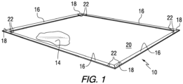
- Fig. 1 shows a berm device 10 in accordance with an embodiment of the present invention.
- the berm device 10 includes multiple compressible liquid impermeable containment walls 16 connected together to form a liquid containment area in which a spill 14, leak, or other liquid is prevented from escaping.
- the compressible containment walls 16 are connected by corner joints 18 to thereby form a closed perimeter of the berm device 10.
- the compressible containment walls 16 and corner joints 18 are directly mounted on a containment surface 20 such as the ground, pavement, floor or the like.
- Connecting straps 22 may be used to connect the compressible containment walls 16 and the corner joints 18.
- the berm device 10 can be formed in the shape of a rectangle surrounding the spill 14.
- the berm device 10 includes four sections of compressible containment walls 16 which define the four sides of the rectangular berm device 10.
- the corner joints 18 may be provided in right-angle configurations as shown. Alternatively, the corner joints 18 can be provided in other configurations to provide a triangular-shaped berm, a pentagonal-shaped berm, or other multiple-sided berm.
- the corner joints 18 can also be configured to provide a berm device 10 in the shape of a parallelogram, octagon or other geometric configuration.
- the berm device 10 has a liquid containment height corresponding to the expanded height of the compressible containment walls 16.
- the compressible containment walls have a typical expanded height of from 1.3 to 45.7 cm (0.5 to 18 inches), for example, from 2.5 to 38.1 cm (1 to 15 inches), or from 5.1 to 30.5 cm (2 to 12 inches).
- the compressed height of the compressible containment walls 16 may typically range from 0.2 to 30.5 cm (0.1 to 12 inches), for example, from 0.4 to 25.4 cm (0.15 to 10 inches), or from 0.5 to 20.3 cm (0.2 to 8 inches).
- the compressed height is from 5 or 10 to 70 percent of the expanded height of the compressible containment wall 16, for example, from 15 or 20 to 60 percent, or from 22 or 25 to 50 percent.
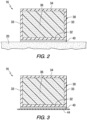
- Figs. 2-6 are cross-sectional views of compressible containment walls 16 in accordance with embodiments of the present invention.
- the compressible containment wall 16 includes a flexible shell 30 having a bottom shell layer 32, sidewalls 33 and a top shell layer 34.
- a compressible filling material 36 is provided inside the flexible shell 30.
- the flexible shell 30 is made of at least one layer of a liquid impermeable, durable material.
- the flexible shell 30 is shown as a continuous layer of material in Figs. 2 and 3 , it has to be understood that the flexible shell 30 may be made from multiple panels of flexible, liquid impermeable material that are connected together by any suitable means including adhesives, welding, sewing, and the like.
- a pre-applied adhesive layer 40 is located on the exterior surface of the bottom shell layer 32.
- pre-applied adhesive means an adhesive layer that is applied to the bottom shell layer 32 during an initial manufacturing or assembly process, rather than being applied separately at an installation site.
- the pre-applied adhesive layer 40 helps to secure and seal the bottom shell layer 32 to the containment surface 20 to thereby reduce or eliminate the flow of spills, leaks or other liquids underneath the compressible containment walls 16.
- a release liner or film 44 may be applied to the bottom surface of the adhesive layer 40 in order to cover the adhesive layer until the compressible containment walls 16 is installed at a containment site.
- the release liner 44 may comprise a thin flexible sheet of material including polymers such as polypropylene, polyethylene and/or polyester, wax and/or silicone coated paper, or the like.
- the thickness of the bottom shell layer 32, sidewalls 33 and top shell layer 34 of the flexible shell 30 may typically range from 0.025 to 12.7 mm
- the thickness may be about 0.64 mm (0.025 inch).
- the flexible shell 30 may be made from any suitable liquid impermeable material such as vinyl, polyurethane, polyols, extruded plastic materials and the like. If made from vinyl or other similar polymeric materials, the flexible shell 30 may typically have a basis weight of from 339-1695 g/m 2 (10 to 50 oz/yd 2 ), for example, from 508-1017 g/m 2 (15 to 30 oz/yd 2 ), or about 610 g/m 2 (18 oz/yd 2 ). In certain embodiments, the flexible polymeric sheet material of the flexible shell 30 may be reinforced with at least one layer of reinforcing material, such as scrim cloth, woven fabric, non-woven fabric, fibers, or the like.
- reinforcing material such as scrim cloth, woven fabric, non-woven fabric, fibers, or the like.
- the compressible fill material 36 may comprise a resilient highly compressible material such as an open-cell foam or closed-cell foam, for example, synthetic rubber, polyolefin or polyurethane open cell foam.
- the compressible material allows the berm to temporarily collapse as equipment is wheeled into the containment area and to return to its original height once the compression force is removed.
- Open-celled foam is advantages over closed-cell foam since it is easier to collapse.
- other resilient compressible materials can be used, such as polymer or metal springs, synthetic fibers or an air bladder.
- any suitable flexible, pliable material can be used as the filler including cellulose, and synthetic or mineral materials.
- the compressible fill material 36 may have a shape retention property such that, when compression is released, the compressible fill material returns to generally its original shape.
- the compressible fill material 36 may have an expanded height of from 1.3 to 40.64 cm (0.5 to 16 inches), and a compressed height of from 0.25 to 20.3 or 25.4 cm (0.1 to 8 or 10 inches).
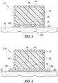
- Fig. 4 illustrates a compressible containment wall 116 in accordance with another embodiment of the present invention. This embodiment is similar to that shown in Figs. 2 and 3 , with the exception that the adhesive layer does not form a continuous sheet across the entire bottom surface of the bottom shell layer 32, but rather comprises a central adhesive strip 40a, and two separate side adhesive strips 40b and 40c.
- Fig. 5 illustrates a compressible containment wall 216 in accordance another embodiment of the present invention.
- the bottom shell layer 32 is extended laterally to form extended bottom strips 32a and 32b on either side of the compressible containment wall 216.
- an extended adhesive layer 40d is provided across the entire bottom surface area of the bottom shell layer 32, including the extended bottom strips 32a in and 32b.
- the adhesive layer maybe provided as discontinuous strips, similar to those shown in the embodiment of Fig. 4 .
- the pre-applied adhesive layer 40 may be a pressure sensitive adhesive (PSA).
- PSA pressure sensitive adhesive
- the adhesive for example, may be natural rubber-based, synthetic rubber-based, acrylic-based, or the like.
- the pre-applied adhesive layer 40 may comprise a cross-linked type PSA that has good chemical resistance.
- the PSA may be applied directly onto the bottom surface of the bottom shell layer 32, or may be applied to a carrier film (not shown) that is then attached to the bottom shell layer 32.
- Suitable carrier films may be made of polypropylene, polyethylene, polyester, nylon, or the like.
- the PSA may have a peel value of from 1.4 to 222 N (5 to 800 ounces force), for example from 11 to 63 N (40 to 225 ounces force), wherein the peel value is measured per the Pressure Sensitive Tape Council test method #PSTC 101.
- the PSA can be a permanent type with a peel force of greater than 63 N (225 ounces force) for applications that do not require relocation of the berm.
- the thickness of the pre-applied adhesive layer 40 may typically range from 0.013 to 6.4 mm (0.0005 to 0.25 inch), for example, from 0.02 to 3.8 mm (0.0008 to 0.15 inch), or from 0.025 to 2.5 mm (0.001 to 0.1 inch). In a particular embodiment, the thickness may be about 0.038 mm (0.0015 inch).
- Fig. 6 illustrates a compressible containment wall 316 in accordance with another embodiment of the present invention.
- the lower most layer of the compressible containment wall 316 comprises an adhesive sealing layer 50 made of a pliable, tacky material, as more fully described below.
- a low-density bonding layer 60 is provided between the bottom shell layer 32 and the pliable, tacky adhesive sealing layer 50.
- the term "low-density bonding layer” means a deep pile or lofty material having at least one surface comprising entanglement fibers that extend from the layer to provide additional surface area and attachment sites for the adjacent bottom shell layer 32 and/or adhesive sealing layer 50.
- a portion of the adhesive sealing layer 50 may be at least partially impregnated into the low-density, bonding layer 60.
- the pliable, tacky material of the adhesive sealing layer 50 may be embedded into the low-density bonding layers a distance of from 1 to 50 or 75 percent of the thickness of the low-density bonding layer 60, for example, from 3 or 5 to 30 or 40 percent.
- the low-density bonding layer 60 helps to secure the adhesive sealing layer 50 to the bottom shell layer 32 during removal and repositioning of the compressible containment walls 16.
- the thickness of the pliable, tacky adhesive sealing layer 50 may typically range from 0.025 to 5.1 cm (0.01 to 2 inch), for example, from 0.13 to 1.3 cm (0.05 to 0.5 inch), or from 0.25 to 0.64 cm (0.1 to 0.25 inch). In a particular embodiment, the thickness may be about 0.32 cm (0.125 inch).
- the thickness of the low-density bonding layer 60 may typically range from 0.025 to 0.25 cm (0.01 to 0.1 inch), for example, from 0.038 to 0.20 cm (0.015 to 0.08 inch), or from 0.76 to 0.15 cm (0.03 to 0.06 inch). In a particular embodiment, the thickness may be about 0.10 cm (0.04 inch).
- the adhesive sealing layer 50 is a pliable, tacky layer that is flexible and tacky in order to conform to irregularities or roughness in the containment surface 20 and adheres to the surface to thereby provide a seal which reduces or eliminates the flow of spilled liquids.
- the adhesive sealing layer 50 may comprise materials such as urethane, polyurethane, polyvinyl chloride and/or silicone.
- the adhesive sealing layer 50 may have a hardness, as measured by a durometer, at least 10 percent less than the hardness of the bottom shell layer 32. In one embodiment, the adhesive sealing layer 50 serves to keep the berm device 10 in its desired location due to its tacky surface.
- the adhesive sealing layer 50 can comprise an inherently tacky material or can have a standard tackifier applied to any exposed surface.
- the adhesive sealing layer 50 has a tackiness such that it adheres to the containment surface 20. In one embodiment, the adhesive sealing layer 50 has sufficient tackiness such that the sealing layer adheres when pressed against a vertical wall. The tackiness of the adhesive sealing layer 50 may also be measured by other test methods known to those skilled in the art, such as rolling ball, peel and probe tests.
- the adhesive layer 50 may consist of a tacky soft polyurethane with maximum durometer of 40 (Shore 00 scale), for example, from 5 to 40, or from 10 to 20, and may have a minimum coating thickness of 0.13 mm up to 2.5 cm (0.005 inches up to 1 inch), for example, from 0.025 to 1.9 cm (0.01 to 0.75 inch), or from 0.13 or 0.25 to 1.27 cm (0.05 or 0.1 to 0.5 inch).
- the low durometer of the soft tacky polyurethane allows it to flow into and fill the cracks and crevices of the surface it is applied to. This is particularly important on rough surfaces, such as macadam, for forming a fluid tight seal between the berm device and the rough containment surface. Thicker coating levels and lower durometer polyurethanes may be preferred since thicker coatings have more polyurethane available to flow into the cracks and crevices while lower durometer polyurethanes flow easily into the voids.
- the low-density bonding layer 60 may be used to achieve a satisfactory bond. Examples of such low-density bonding layers are described in U.S. Patent No. 8,117,686 .
- a mixture of various polyurethanes can be used to make the adhesive sealing layer 50.
- a typical polyurethane mixture comprises from about 50 to about 90 weight percent polyol, and from about 10 to about 50 weight percent isocyanate prepolymer.
- the liquid polyurethane is mixed and cured in a manner which gives it a moderate degree of inherent tackiness to all exposed surfaces of the polyurethane material.
- the molding and curing process creates a substantially smooth exposed surface, which may contain minor undulations.
- the polyurethane material is soft, yet resilient, and thus may be easily severed by a user with a knife. Surfaces of the polyurethane material which are exposed when a portion of it is severed can also be inherently tacky. While a process is described above for manufacturing polyurethane having an inherent tackiness, one skilled in the art will appreciate that other materials, such as, for example, vinyls, silicones and rubbers, may also be modified to have an inherent tackiness.
- the low-density bonding layer 60 is provided between the bottom shell layer 32 and the adhesive sealing layer 50.
- the low-density bonding layer 60 has a density that is typically less than 450 kg/m 3 (0.26 ounces per cubic inch), preferably from 35 to 173 kg/m 3 (0.02 to 0.1 ounces per cubic inch).
- the low-density bonding layer 60 typically has a weight per area of less than 678 g/m 2 (20 ounces per square yard), for example, from 34 to 339 g/m 2 (1 to 10 ounces per square yard).
- the low-density bonding layer 20 provides secure and permanent attachment between the bottom shell layer 32 and the adhesive sealing layer 50, while maintaining separation between the materials of the adjacent layers 32 and 50. In contrast with an open mesh or permeable screen material that would allow the layers 32 and 50 to contact each other, the low-density bonding layer 60 maintains separation between the layers 32 and 50.
- the low-density bonding layer 60 may be non-woven and may comprise entanglement fibers made of polyester, polypropylene, polyethylene propylene), polyvinylchloride, fiberglass, nylon, cotton, urethane and the like.
- the low-density bonding layer 60 comprises a base or backing layer from which the entanglement fibers extend on one or both sides of the backing layer.
- the low-density bonding layer 60 may comprise fleece made of polyester and having a thickness of about 0.1 cm (0.04 inch). The fleece assists in the adhesion of the bottom shell layer 32 and the adhesive sealing layer 50.
- the low-density bonding layer 60 may also provide puncture resistance.
- the low-density bonding layer 60 may be adhered to the underside of the bottom shell layer 32 by any suitable means such as adhesives, co-extrusion, thermal welding, sonic welding, RF welding, or the like.
- an adhesive such as a pressure sensitive adhesive may be applied directly to the bottom shell layer 32 without the need for an intermediate layer.
- the pressure sensitive adhesive may be the pre-applied to a carrier film (not shown), which is bonded to the bottom shell layer 32, i.e., the carrier film may be used as an intermediate layer.
- the carrier film may be polyethylene, polypropylene, nylon, polyester or the like, for example, polyethylene having a thickness of from 0.019 to 0.076 mm (0.00075 to 0.003 inches (0.75 to 3 mils)).
- the carrier layer may be bonded to the bottom shell layer 32 with a polyolefin-based hot melt adhesive, by thermal, sonic or RF welding, or the like.
- compressible containment walls 16, 116, 216 and 316 are illustrated as having rectangular cross-sections in the figures, any other suitable cross-sectional shape may be used, such as square, triangular, trapezoidal, semi-circular or the like.
- the berm device 10 may come in various lengths and shapes, such as straight sections, curved sections, 45° and 90° corner sections, termination ends and freely formable sections, all of which can be fitted and sealed together to form any size or shape fluid containment area that is required.
- the freely formable sections are laterally flexible enough to permit forming curvilinear shapes as the berm is installed.
- the self-adhering capability of the berm device 10 eliminates the need to apply sealing adhesive to the berm before installation and eliminates the need for mechanical fasteners. This results in time savings during installation and a savings on labor to install.
- the berm device of the present invention can be provided in a kit that includes at least one coil of compressible containment walls, at least four right-angled corner joints, and a sheet of vinyl strapping.
- the coils of compressible containment walls can be cut with a sharp object such as scissors or a utility knife to a desired length.
- the corner joints may be set against the cut compressible containment walls to allow for a custom fit of a specific containment area.
- the compressible containment wall sections and corner joints are pressed into place to make proper contact.
- the strapping material can be cut into desired length to cover any areas that were exposed during cutting of the ends of the compressible containment walls.
- the strapping material may be applied to the compressible containment walls and corner joints by means of standard strapping glue.
- the strapping material may also be integrally formed on the end of the compressible containment wall sections, for example, as an overhanging length or flap of the flexible sidewall material and/or top shell layer of the flexible shell.
- the flap can overlay adjacent compressible containment wall sections and be joined by an appropriate adhesive.
- the compressible containment wall sections can be cut from a longer strip of material at the work site in order to construct a berm having the desired dimensions.
- the ability to cut the compressible containment wall sections to size affords an added degree of flexibility, which allows the berm devices of the present invention to be used for any number of configurations.
Landscapes
- Engineering & Computer Science (AREA)
- General Engineering & Computer Science (AREA)
- Structural Engineering (AREA)
- Mechanical Engineering (AREA)
- Civil Engineering (AREA)
- Life Sciences & Earth Sciences (AREA)
- Environmental & Geological Engineering (AREA)
- Hydrology & Water Resources (AREA)
- General Life Sciences & Earth Sciences (AREA)
- Mining & Mineral Resources (AREA)
- Paleontology (AREA)
- Adhesives Or Adhesive Processes (AREA)
- Laminated Bodies (AREA)
- Road Paving Structures (AREA)
Applications Claiming Priority (2)
| Application Number | Priority Date | Filing Date | Title |
|---|---|---|---|
| US201662305668P | 2016-03-09 | 2016-03-09 | |
| PCT/US2017/021344 WO2017156117A1 (en) | 2016-03-09 | 2017-03-08 | Soil protection |
Publications (3)
| Publication Number | Publication Date |
|---|---|
| EP3426849A1 EP3426849A1 (en) | 2019-01-16 |
| EP3426849C0 EP3426849C0 (en) | 2023-06-14 |
| EP3426849B1 true EP3426849B1 (en) | 2023-06-14 |
Family
ID=58402137
Family Applications (1)
| Application Number | Title | Priority Date | Filing Date |
|---|---|---|---|
| EP17713103.4A Active EP3426849B1 (en) | 2016-03-09 | 2017-03-08 | Soil protection |
Country Status (7)
| Country | Link |
|---|---|
| US (1) | US20170260709A1 (enExample) |
| EP (1) | EP3426849B1 (enExample) |
| JP (1) | JP2019507838A (enExample) |
| CN (1) | CN109477324A (enExample) |
| AU (1) | AU2017231663A1 (enExample) |
| CA (1) | CA3017343A1 (enExample) |
| WO (1) | WO2017156117A1 (enExample) |
Families Citing this family (5)
| Publication number | Priority date | Publication date | Assignee | Title |
|---|---|---|---|---|
| USD790731S1 (en) * | 2014-12-05 | 2017-06-27 | Well Service Group, Inc. | Beveled berm |
| CN109208652B (zh) * | 2018-09-30 | 2020-11-06 | 安徽送变电工程有限公司 | 一种混凝土基础用折叠伸缩式保护装置 |
| CN111132462A (zh) * | 2019-12-25 | 2020-05-08 | 奥士康科技股份有限公司 | 一种药水泄漏用担架式接漏器 |
| USD1019991S1 (en) * | 2020-02-06 | 2024-03-26 | Newpark Mats & Integrated Services Llc | Berm with smooth transition groove |
| CN115126007B (zh) * | 2022-07-29 | 2023-02-24 | 山东大学 | 一种静压式柔性隔振气囊插板机及施工方法 |
Citations (4)
| Publication number | Priority date | Publication date | Assignee | Title |
|---|---|---|---|---|
| US6648008B1 (en) * | 2001-05-10 | 2003-11-18 | Price Kerrigan Mcgrew | Method and apparatus for wash water containment and disposal |
| US20070207306A1 (en) * | 2006-03-03 | 2007-09-06 | New Pig Corporation | Expanding tape barrier |
| US20140256533A1 (en) * | 2013-03-11 | 2014-09-11 | New Pig Corporation | Absorbent containment mats |
| US20160194849A1 (en) * | 2015-01-06 | 2016-07-07 | Garland Industries, Inc. | Containment Membrane |
Family Cites Families (17)
| Publication number | Priority date | Publication date | Assignee | Title |
|---|---|---|---|---|
| DE3824485A1 (de) * | 1988-07-20 | 1990-01-25 | Bayer Ag | Senkenverschluss |
| US5236281A (en) * | 1992-07-15 | 1993-08-17 | New Pig Corporation | Dikes for damming or diverting liquids |
| US5820297A (en) * | 1996-08-27 | 1998-10-13 | New Pig Corporation | Permanent berm device |
| US6861141B2 (en) * | 1996-12-04 | 2005-03-01 | Gina M. Buccellato | Pavement marking article and raised pavement marker that uses pressure sensitive adhesive |
| US5762233A (en) * | 1997-05-07 | 1998-06-09 | Van Romer; Edward W. | Foldable spill collector container |
| US6129964A (en) * | 1997-11-06 | 2000-10-10 | 3M Innovative Properties Company | Nonwoven pressure sensitive adhesive tape |
| US20030123930A1 (en) * | 2001-12-31 | 2003-07-03 | Jacobs Gregory F. | Matrix element magnetic pavement marker and method of making same |
| US8117686B2 (en) * | 2003-05-28 | 2012-02-21 | New Pig Corporation | Durable protective cover for preventing spilled liquids from flowing into drains or holes |
| US8088480B2 (en) * | 2003-09-29 | 2012-01-03 | Shieldmark, Inc. | Adhesive tape |
| US7618402B2 (en) * | 2004-04-06 | 2009-11-17 | Johnsondiversey, Inc. | Fluid absorbent tape |
| DE102006033796A1 (de) * | 2006-07-19 | 2008-01-31 | Tesa Ag | Haftklebestoffe aus einem harzmodifizierten Polyurethan |
| CN201183959Y (zh) * | 2008-03-18 | 2009-01-21 | 成都铁瑞工程材料有限公司 | 复合防排水板 |
| US8464885B2 (en) * | 2010-01-15 | 2013-06-18 | Argonaut Inflatable Research And Engineering, Inc. | Inside stay and inside stay berm unit |
| US20110318548A1 (en) * | 2010-06-28 | 2011-12-29 | New Pig Corporation | Adhesive Backed Absorbent Mat |
| US9517596B2 (en) * | 2011-02-24 | 2016-12-13 | New Pig Corporation | Ground containment liners |
| US8479946B2 (en) * | 2011-06-09 | 2013-07-09 | Matson, Inc. | Portable drip containment device apparatus and method |
| US8979433B2 (en) * | 2012-03-27 | 2015-03-17 | Mark D. Shaw | Liquid containment berm and method of use |
-
2017
- 2017-03-08 WO PCT/US2017/021344 patent/WO2017156117A1/en not_active Ceased
- 2017-03-08 US US15/453,220 patent/US20170260709A1/en not_active Abandoned
- 2017-03-08 CN CN201780024230.3A patent/CN109477324A/zh active Pending
- 2017-03-08 CA CA3017343A patent/CA3017343A1/en not_active Abandoned
- 2017-03-08 EP EP17713103.4A patent/EP3426849B1/en active Active
- 2017-03-08 JP JP2018547997A patent/JP2019507838A/ja active Pending
- 2017-03-08 AU AU2017231663A patent/AU2017231663A1/en not_active Abandoned
Patent Citations (4)
| Publication number | Priority date | Publication date | Assignee | Title |
|---|---|---|---|---|
| US6648008B1 (en) * | 2001-05-10 | 2003-11-18 | Price Kerrigan Mcgrew | Method and apparatus for wash water containment and disposal |
| US20070207306A1 (en) * | 2006-03-03 | 2007-09-06 | New Pig Corporation | Expanding tape barrier |
| US20140256533A1 (en) * | 2013-03-11 | 2014-09-11 | New Pig Corporation | Absorbent containment mats |
| US20160194849A1 (en) * | 2015-01-06 | 2016-07-07 | Garland Industries, Inc. | Containment Membrane |
Also Published As
| Publication number | Publication date |
|---|---|
| EP3426849A1 (en) | 2019-01-16 |
| EP3426849C0 (en) | 2023-06-14 |
| WO2017156117A1 (en) | 2017-09-14 |
| CN109477324A (zh) | 2019-03-15 |
| JP2019507838A (ja) | 2019-03-22 |
| AU2017231663A1 (en) | 2018-10-04 |
| CA3017343A1 (en) | 2017-09-14 |
| US20170260709A1 (en) | 2017-09-14 |
Similar Documents
| Publication | Publication Date | Title |
|---|---|---|
| EP3426849B1 (en) | Soil protection | |
| US8117686B2 (en) | Durable protective cover for preventing spilled liquids from flowing into drains or holes | |
| WO2008130091A1 (en) | Un-vulcanized synthetic rubber sheets-waterproof material of self-adhesion type and construction method using the same | |
| US8104245B2 (en) | Method for waterproofing a structural surface | |
| US8778497B2 (en) | Underlayment mat employed with a single-ply roofing system | |
| US20180065800A1 (en) | Portable containment units and methods for making same | |
| US20120058309A1 (en) | Sealing Tape of Flexible Foam | |
| CA2281011A1 (en) | Tear/puncture resistant semi-laminate material | |
| AU2018427211C1 (en) | Fish-mouth-resistant waterproofing membrane | |
| US7950075B2 (en) | Protective cover for preventing spilled liquids from flowing into drains or holes | |
| EP3515701B1 (en) | Durable protective covers with stiffening rods for preventing spilled liquids from flowing into drains or holes | |
| WO2015171706A1 (en) | Protective mat and method for protecting a floor from spillage and debris | |
| US20120027520A1 (en) | Reinforced Dikes For Damming Or Diverting Liquids | |
| CA2598886C (en) | Self-adhering waterproofing membrane | |
| JPH08207186A (ja) | 断熱防水シート | |
| JPH045635Y2 (enExample) | ||
| HK1079736B (zh) | 制作防水材料的方法 | |
| JP3138391U (ja) | 養生マット | |
| JP2020012234A (ja) | 型枠用テープ、コンクリート型枠構造体及びコンクリート製建築物の製造方法 |
Legal Events
| Date | Code | Title | Description |
|---|---|---|---|
| STAA | Information on the status of an ep patent application or granted ep patent |
Free format text: STATUS: UNKNOWN |
|
| STAA | Information on the status of an ep patent application or granted ep patent |
Free format text: STATUS: THE INTERNATIONAL PUBLICATION HAS BEEN MADE |
|
| PUAI | Public reference made under article 153(3) epc to a published international application that has entered the european phase |
Free format text: ORIGINAL CODE: 0009012 |
|
| STAA | Information on the status of an ep patent application or granted ep patent |
Free format text: STATUS: REQUEST FOR EXAMINATION WAS MADE |
|
| 17P | Request for examination filed |
Effective date: 20181008 |
|
| AK | Designated contracting states |
Kind code of ref document: A1 Designated state(s): AL AT BE BG CH CY CZ DE DK EE ES FI FR GB GR HR HU IE IS IT LI LT LU LV MC MK MT NL NO PL PT RO RS SE SI SK SM TR |
|
| AX | Request for extension of the european patent |
Extension state: BA ME |
|
| DAV | Request for validation of the european patent (deleted) | ||
| DAX | Request for extension of the european patent (deleted) | ||
| STAA | Information on the status of an ep patent application or granted ep patent |
Free format text: STATUS: EXAMINATION IS IN PROGRESS |
|
| 17Q | First examination report despatched |
Effective date: 20200128 |
|
| GRAP | Despatch of communication of intention to grant a patent |
Free format text: ORIGINAL CODE: EPIDOSNIGR1 |
|
| STAA | Information on the status of an ep patent application or granted ep patent |
Free format text: STATUS: GRANT OF PATENT IS INTENDED |
|
| INTG | Intention to grant announced |
Effective date: 20230109 |
|
| GRAS | Grant fee paid |
Free format text: ORIGINAL CODE: EPIDOSNIGR3 |
|
| GRAA | (expected) grant |
Free format text: ORIGINAL CODE: 0009210 |
|
| STAA | Information on the status of an ep patent application or granted ep patent |
Free format text: STATUS: THE PATENT HAS BEEN GRANTED |
|
| AK | Designated contracting states |
Kind code of ref document: B1 Designated state(s): AL AT BE BG CH CY CZ DE DK EE ES FI FR GB GR HR HU IE IS IT LI LT LU LV MC MK MT NL NO PL PT RO RS SE SI SK SM TR |
|
| REG | Reference to a national code |
Ref country code: CH Ref legal event code: EP |
|
| REG | Reference to a national code |
Ref country code: DE Ref legal event code: R096 Ref document number: 602017070172 Country of ref document: DE |
|
| REG | Reference to a national code |
Ref country code: AT Ref legal event code: REF Ref document number: 1579320 Country of ref document: AT Kind code of ref document: T Effective date: 20230715 |
|
| U01 | Request for unitary effect filed |
Effective date: 20230621 |
|
| U07 | Unitary effect registered |
Designated state(s): AT BE BG DE DK EE FI FR IT LT LU LV MT NL PT SE SI Effective date: 20230719 |
|
| REG | Reference to a national code |
Ref country code: LT Ref legal event code: MG9D |
|
| PG25 | Lapsed in a contracting state [announced via postgrant information from national office to epo] |
Ref country code: NO Free format text: LAPSE BECAUSE OF FAILURE TO SUBMIT A TRANSLATION OF THE DESCRIPTION OR TO PAY THE FEE WITHIN THE PRESCRIBED TIME-LIMIT Effective date: 20230914 Ref country code: ES Free format text: LAPSE BECAUSE OF FAILURE TO SUBMIT A TRANSLATION OF THE DESCRIPTION OR TO PAY THE FEE WITHIN THE PRESCRIBED TIME-LIMIT Effective date: 20230614 |
|
| PG25 | Lapsed in a contracting state [announced via postgrant information from national office to epo] |
Ref country code: RS Free format text: LAPSE BECAUSE OF FAILURE TO SUBMIT A TRANSLATION OF THE DESCRIPTION OR TO PAY THE FEE WITHIN THE PRESCRIBED TIME-LIMIT Effective date: 20230614 Ref country code: HR Free format text: LAPSE BECAUSE OF FAILURE TO SUBMIT A TRANSLATION OF THE DESCRIPTION OR TO PAY THE FEE WITHIN THE PRESCRIBED TIME-LIMIT Effective date: 20230614 Ref country code: GR Free format text: LAPSE BECAUSE OF FAILURE TO SUBMIT A TRANSLATION OF THE DESCRIPTION OR TO PAY THE FEE WITHIN THE PRESCRIBED TIME-LIMIT Effective date: 20230915 |
|
| PG25 | Lapsed in a contracting state [announced via postgrant information from national office to epo] |
Ref country code: SK Free format text: LAPSE BECAUSE OF FAILURE TO SUBMIT A TRANSLATION OF THE DESCRIPTION OR TO PAY THE FEE WITHIN THE PRESCRIBED TIME-LIMIT Effective date: 20230614 |
|
| PG25 | Lapsed in a contracting state [announced via postgrant information from national office to epo] |
Ref country code: IS Free format text: LAPSE BECAUSE OF FAILURE TO SUBMIT A TRANSLATION OF THE DESCRIPTION OR TO PAY THE FEE WITHIN THE PRESCRIBED TIME-LIMIT Effective date: 20231014 |
|
| PG25 | Lapsed in a contracting state [announced via postgrant information from national office to epo] |
Ref country code: SM Free format text: LAPSE BECAUSE OF FAILURE TO SUBMIT A TRANSLATION OF THE DESCRIPTION OR TO PAY THE FEE WITHIN THE PRESCRIBED TIME-LIMIT Effective date: 20230614 Ref country code: SK Free format text: LAPSE BECAUSE OF FAILURE TO SUBMIT A TRANSLATION OF THE DESCRIPTION OR TO PAY THE FEE WITHIN THE PRESCRIBED TIME-LIMIT Effective date: 20230614 Ref country code: RO Free format text: LAPSE BECAUSE OF FAILURE TO SUBMIT A TRANSLATION OF THE DESCRIPTION OR TO PAY THE FEE WITHIN THE PRESCRIBED TIME-LIMIT Effective date: 20230614 Ref country code: IS Free format text: LAPSE BECAUSE OF FAILURE TO SUBMIT A TRANSLATION OF THE DESCRIPTION OR TO PAY THE FEE WITHIN THE PRESCRIBED TIME-LIMIT Effective date: 20231014 Ref country code: CZ Free format text: LAPSE BECAUSE OF FAILURE TO SUBMIT A TRANSLATION OF THE DESCRIPTION OR TO PAY THE FEE WITHIN THE PRESCRIBED TIME-LIMIT Effective date: 20230614 |
|
| PG25 | Lapsed in a contracting state [announced via postgrant information from national office to epo] |
Ref country code: PL Free format text: LAPSE BECAUSE OF FAILURE TO SUBMIT A TRANSLATION OF THE DESCRIPTION OR TO PAY THE FEE WITHIN THE PRESCRIBED TIME-LIMIT Effective date: 20230614 |
|
| REG | Reference to a national code |
Ref country code: DE Ref legal event code: R097 Ref document number: 602017070172 Country of ref document: DE |
|
| PLBE | No opposition filed within time limit |
Free format text: ORIGINAL CODE: 0009261 |
|
| STAA | Information on the status of an ep patent application or granted ep patent |
Free format text: STATUS: NO OPPOSITION FILED WITHIN TIME LIMIT |
|
| U20 | Renewal fee for the european patent with unitary effect paid |
Year of fee payment: 8 Effective date: 20240327 |
|
| 26N | No opposition filed |
Effective date: 20240315 |
|
| REG | Reference to a national code |
Ref country code: CH Ref legal event code: PL |
|
| PG25 | Lapsed in a contracting state [announced via postgrant information from national office to epo] |
Ref country code: MC Free format text: LAPSE BECAUSE OF FAILURE TO SUBMIT A TRANSLATION OF THE DESCRIPTION OR TO PAY THE FEE WITHIN THE PRESCRIBED TIME-LIMIT Effective date: 20230614 |
|
| PG25 | Lapsed in a contracting state [announced via postgrant information from national office to epo] |
Ref country code: MC Free format text: LAPSE BECAUSE OF FAILURE TO SUBMIT A TRANSLATION OF THE DESCRIPTION OR TO PAY THE FEE WITHIN THE PRESCRIBED TIME-LIMIT Effective date: 20230614 |
|
| PG25 | Lapsed in a contracting state [announced via postgrant information from national office to epo] |
Ref country code: IE Free format text: LAPSE BECAUSE OF NON-PAYMENT OF DUE FEES Effective date: 20240308 |
|
| PG25 | Lapsed in a contracting state [announced via postgrant information from national office to epo] |
Ref country code: IE Free format text: LAPSE BECAUSE OF NON-PAYMENT OF DUE FEES Effective date: 20240308 Ref country code: CH Free format text: LAPSE BECAUSE OF NON-PAYMENT OF DUE FEES Effective date: 20240331 |
|
| PGFP | Annual fee paid to national office [announced via postgrant information from national office to epo] |
Ref country code: GB Payment date: 20250327 Year of fee payment: 9 |
|
| U20 | Renewal fee for the european patent with unitary effect paid |
Year of fee payment: 9 Effective date: 20250327 |
|
| PG25 | Lapsed in a contracting state [announced via postgrant information from national office to epo] |
Ref country code: CY Free format text: LAPSE BECAUSE OF FAILURE TO SUBMIT A TRANSLATION OF THE DESCRIPTION OR TO PAY THE FEE WITHIN THE PRESCRIBED TIME-LIMIT; INVALID AB INITIO Effective date: 20170308 |
|
| PG25 | Lapsed in a contracting state [announced via postgrant information from national office to epo] |
Ref country code: HU Free format text: LAPSE BECAUSE OF FAILURE TO SUBMIT A TRANSLATION OF THE DESCRIPTION OR TO PAY THE FEE WITHIN THE PRESCRIBED TIME-LIMIT; INVALID AB INITIO Effective date: 20170308 |
|
| PG25 | Lapsed in a contracting state [announced via postgrant information from national office to epo] |
Ref country code: TR Free format text: LAPSE BECAUSE OF FAILURE TO SUBMIT A TRANSLATION OF THE DESCRIPTION OR TO PAY THE FEE WITHIN THE PRESCRIBED TIME-LIMIT Effective date: 20230614 |