EP3426451B1 - A press for the production of ceramic products - Google Patents
A press for the production of ceramic products Download PDFInfo
- Publication number
- EP3426451B1 EP3426451B1 EP17719907.2A EP17719907A EP3426451B1 EP 3426451 B1 EP3426451 B1 EP 3426451B1 EP 17719907 A EP17719907 A EP 17719907A EP 3426451 B1 EP3426451 B1 EP 3426451B1
- Authority
- EP
- European Patent Office
- Prior art keywords
- plane surface
- face
- perforations
- belt
- pressing plane
- Prior art date
- Legal status (The legal status is an assumption and is not a legal conclusion. Google has not performed a legal analysis and makes no representation as to the accuracy of the status listed.)
- Active
Links
- 239000000919 ceramic Substances 0.000 title claims description 15
- 238000004519 manufacturing process Methods 0.000 title claims description 9
- 238000003825 pressing Methods 0.000 claims description 84
- 239000000843 powder Substances 0.000 claims description 32
- 229910010293 ceramic material Inorganic materials 0.000 claims description 26
- 239000000463 material Substances 0.000 claims description 22
- 239000012530 fluid Substances 0.000 claims description 13
- 238000004891 communication Methods 0.000 claims description 9
- 230000007423 decrease Effects 0.000 claims description 4
- 239000000047 product Substances 0.000 description 11
- 239000007789 gas Substances 0.000 description 7
- 238000000034 method Methods 0.000 description 6
- 239000000203 mixture Substances 0.000 description 5
- 230000008569 process Effects 0.000 description 5
- 238000009826 distribution Methods 0.000 description 4
- 239000000654 additive Substances 0.000 description 2
- 238000005056 compaction Methods 0.000 description 2
- 229920001971 elastomer Polymers 0.000 description 2
- 239000011148 porous material Substances 0.000 description 2
- 238000007789 sealing Methods 0.000 description 2
- 229910000831 Steel Inorganic materials 0.000 description 1
- 238000013459 approach Methods 0.000 description 1
- 230000002860 competitive effect Effects 0.000 description 1
- 230000001419 dependent effect Effects 0.000 description 1
- 239000004744 fabric Substances 0.000 description 1
- 238000001914 filtration Methods 0.000 description 1
- 239000012467 final product Substances 0.000 description 1
- 239000002184 metal Substances 0.000 description 1
- 229910001092 metal group alloy Inorganic materials 0.000 description 1
- 238000012986 modification Methods 0.000 description 1
- 230000004048 modification Effects 0.000 description 1
- 230000037361 pathway Effects 0.000 description 1
- 229920001296 polysiloxane Polymers 0.000 description 1
- 229920002635 polyurethane Polymers 0.000 description 1
- 239000004814 polyurethane Substances 0.000 description 1
- 229920000915 polyvinyl chloride Polymers 0.000 description 1
- 238000012545 processing Methods 0.000 description 1
- 230000001681 protective effect Effects 0.000 description 1
- 230000009467 reduction Effects 0.000 description 1
- 239000010959 steel Substances 0.000 description 1
- 238000006467 substitution reaction Methods 0.000 description 1
- XLYOFNOQVPJJNP-UHFFFAOYSA-N water Substances O XLYOFNOQVPJJNP-UHFFFAOYSA-N 0.000 description 1
Images


Classifications
-
- B—PERFORMING OPERATIONS; TRANSPORTING
- B28—WORKING CEMENT, CLAY, OR STONE
- B28B—SHAPING CLAY OR OTHER CERAMIC COMPOSITIONS; SHAPING SLAG; SHAPING MIXTURES CONTAINING CEMENTITIOUS MATERIAL, e.g. PLASTER
- B28B3/00—Producing shaped articles from the material by using presses; Presses specially adapted therefor
- B28B3/02—Producing shaped articles from the material by using presses; Presses specially adapted therefor wherein a ram exerts pressure on the material in a moulding space; Ram heads of special form
-
- B—PERFORMING OPERATIONS; TRANSPORTING
- B28—WORKING CEMENT, CLAY, OR STONE
- B28B—SHAPING CLAY OR OTHER CERAMIC COMPOSITIONS; SHAPING SLAG; SHAPING MIXTURES CONTAINING CEMENTITIOUS MATERIAL, e.g. PLASTER
- B28B5/00—Producing shaped articles from the material in moulds or on moulding surfaces, carried or formed by, in or on conveyors irrespective of the manner of shaping
- B28B5/02—Producing shaped articles from the material in moulds or on moulding surfaces, carried or formed by, in or on conveyors irrespective of the manner of shaping on conveyors of the endless-belt or chain type
- B28B5/021—Producing shaped articles from the material in moulds or on moulding surfaces, carried or formed by, in or on conveyors irrespective of the manner of shaping on conveyors of the endless-belt or chain type the shaped articles being of definite length
-
- B—PERFORMING OPERATIONS; TRANSPORTING
- B28—WORKING CEMENT, CLAY, OR STONE
- B28B—SHAPING CLAY OR OTHER CERAMIC COMPOSITIONS; SHAPING SLAG; SHAPING MIXTURES CONTAINING CEMENTITIOUS MATERIAL, e.g. PLASTER
- B28B7/00—Moulds; Cores; Mandrels
- B28B7/0002—Auxiliary parts or elements of the mould
- B28B7/0008—Venting channels, e.g. to avoid vacuum during demoulding or allowing air to escape during feeding, pressing or moulding
-
- B—PERFORMING OPERATIONS; TRANSPORTING
- B28—WORKING CEMENT, CLAY, OR STONE
- B28B—SHAPING CLAY OR OTHER CERAMIC COMPOSITIONS; SHAPING SLAG; SHAPING MIXTURES CONTAINING CEMENTITIOUS MATERIAL, e.g. PLASTER
- B28B7/00—Moulds; Cores; Mandrels
- B28B7/40—Moulds; Cores; Mandrels characterised by means for modifying the properties of the moulding material
- B28B7/44—Moulds; Cores; Mandrels characterised by means for modifying the properties of the moulding material for treating with gases or degassing, e.g. for de-aerating
-
- B—PERFORMING OPERATIONS; TRANSPORTING
- B30—PRESSES
- B30B—PRESSES IN GENERAL
- B30B15/00—Details of, or accessories for, presses; Auxiliary measures in connection with pressing
- B30B15/0005—Details of, or accessories for, presses; Auxiliary measures in connection with pressing for briquetting presses
- B30B15/0017—Deairing means
-
- B—PERFORMING OPERATIONS; TRANSPORTING
- B30—PRESSES
- B30B—PRESSES IN GENERAL
- B30B15/00—Details of, or accessories for, presses; Auxiliary measures in connection with pressing
- B30B15/02—Dies; Inserts therefor; Mounting thereof; Moulds
- B30B15/022—Moulds for compacting material in powder, granular of pasta form
Definitions
- the present invention generally regards the technical field of presses for the dry production of ceramic products, in particular tiles or plates, even of large size, in which the ceramic material to be pressed is fed by a conveyor belt.
- the making of ceramic tiles or plates can occur under dry conditions, by means of the compaction of a mass of ceramic material in the form of a mixture of ceramic powders and possible other additives.
- the dry compaction of one such mixture of powder ceramic material occurs in a press, more particularly at a forming seat thereof into which the mass of powder ceramic material to be compacted is fed, e.g. arranging it directly in a forming seat or transporting it by means of suitable feeding means, for example a conveyor belt.
- the forming seat remains delimited between two opposite plane surfaces which are substantially non-deformable and parallel to each other, mutually movable away from and towards the other. More particularly, the forming seat comprises a first pressing plane surface, lower during use, having mold function and intended to receive the mass of powder ceramic material to be compacted and a second plane surface, upper during use, having the function of punch or counter-mold.
- first pressing plane surface lower during use
- second plane surface upper during use, having the function of punch or counter-mold.
- the material to be compacted is fed by means of the above feeding means, e.g. a conveyor belt which traverses the forming seat between the two opposite plane surfaces, the powder ceramic material to be compacted is directly compressed on the conveyor belt and then conveyed to the outlet by the belt itself, at the end of the process.
- a conveyor belt which traverses the forming seat between the two opposite plane surfaces
- the mass of powder ceramic material to be compacted has a high air content, even 50%, which during the pressing step must exit outward from the material in a uniform manner, in order to ensure a good quality of the final product.
- the pressing can occur in multiple successive steps, and in each of these the pressure applied to the mass of powder ceramic material is different.
- the pressing times can be lengthened.
- the pressing process is complicated since the operation in successive steps of the press must be suitably controlled and coordinated with the other components of the press itself, for example the starting members and the conveyor belt.
- the pressing times of rather long duration can compromise the efficiency of the production.
- EP0793565A1 , US2014141961A1 , EP2364830A1 , EP2384870A1 teach solutions according to the state of the prior art.
- WO2014/101993 discloses a conveyor belt designed for transporting plate-shaped items in a processing machine, comprising a belt body, having longitudinal edges, connecting edges, and a support face, shaped to support the items, and at least one assembling member, arranged so as to join the connecting edges, and extending in an assembling direction that is oblique relative to the longitudinal direction; the belt body has a plurality of perforations that make it possible to obtain a vacuum on the support face, so as to immobilise the items.
- ITMO20100268 discloses an apparatus for forming substantially slab-shaped products according to the preamble of claim 1, comprising a conveyor belt provided with an inlet side at which material to be formed is fed, an outlet side in correspondence of which formed articles are removed, and pressing means of said material to be formed, provided with at least one half-mold positioned above the upper branch of the conveyor belt, and alternatively mobile approaching and moving away from it according to a pressing direction.
- the conveyor belt is made of porous material, permeable to at least one fluid medium;
- the pressing means comprise at least one abutment body of the half-mold during pressing, which is positioned below the upper branch of the conveyor belt in correspondence with the half-mold, and which defines a bearing surface of the upper branch of the conveyor belt itself, during the pressing stage;
- the supporting surface is provided with at least one opening in communication with a chamber, defined internally to the abutment body, for collecting the fluid medium evacuated from the material during pressing through the pores of the conveyor belt.
- the main object of the present invention is to improve the state of the art of presses for the dry production of ceramic products, in particular tiles or plates of large size.
- one object of the present invention is to provide a press for making ceramic products which allows obtaining products of high quality in relatively limited times with respect to the pressing times of the conventional presses.
- Another object of the present invention is to provide a press for making ceramic products that is easy to make, also at competitive costs.
- the press for the dry production of a ceramic product is generically indicated with the reference number 1 and comprises at least one first pressing plane surface 2 and one second pressing plane surface 3, arranged substantially parallel to each other.
- the first pressing plane surface 2 is arranged below the second pressing plane surface 3 and lies on a substantially horizontal plane.
- the pressing plane surfaces 2 and 3 are mutually movable towards and away from each other by means of suitable power means, not illustrated in the figures, so that the plane surfaces can approach or move away from each other.
- a mass 4 of ceramic material to be compacted is arranged, in the form of a mixture of ceramic powders and possible other additives.
- At least one between the first pressing plane surface 2 and the second pressing plane surface 3 (in the illustrated figures, only the first pressing plane surface 2) comprises a first face 5 facing towards the mass 4 of ceramic material to be compacted and a second face 6, connectable with suitable suction means, not visible in the drawings, e.g. a vacuum pump.
- a manifold circuit 7 for gas is obtained, comprising a plurality of ducts 70 as well as first openings 8, obtained at the first face 5, facing towards the powder material to be compacted, and second openings 9, obtained at the second face 6.
- first and the second openings 8, 9 are in fluid communication with each other by means of the plurality of ducts 70.
- the second face 6 of the pressing plane surface 2 is a lateral face of the plane surface itself. Nevertheless, such face could be the face opposite the first face 5, or directed opposite the mass 4 of powder ceramic material to be compacted.
- the plurality of ducts 70 leads, on one side, onto the first face 5, at the first openings 8 and, on the other side, onto the second face 6, at the second openings 9, for the connection with the abovementioned suction means.
- the first face 5 of the pressing plane surface affected by the manifold circuit 7, in the illustrated case the first pressing plane surface 2 is made of compact material (i.e. non-porous) that is impermeable to gas, e.g. metal or metal alloy, preferably high-tensile steel capable of supporting the specific required pressing pressure (up to 500 kg/cm2), e.g. C45.
- the first openings 8, obtained in the first face 5 of the pressing plane surface 2 are uniformly distributed on such first face and have a diameter less than or equal to 1 mm.
- the first openings 8 are obtained in the first face 5 of the pressing plane surface 2 according to a grid configuration.
- the plurality of ducts 70 comprises at least one main duct 71 and a plurality of secondary ducts 72 in fluid communication with each other, each secondary duct 72 leading, on one side, through a respective first opening 8, onto the first face 5 of the plane surface 2 and on the other side, into the main duct 71 and each main duct 71, in turn, leading on one side, into respective secondary ducts 72 and, on the other side, through a second opening 9, onto second face 6.
- the secondary ducts 72 are arranged substantially orthogonal to the main duct 71. In any case, other configurations of the plurality of ducts 70 can be provided for, so long as they allow the fluid communication between the first face 5 of the pressing plane surface 2 and the second face 6 thereof.
- each secondary duct 72 comprises a first portion 721, at the respective first opening 8, and a second portion 722, facing towards the respective main duct 71, as well as an intermediate portion 723 for the connection between the first portion 721 and the second portion 722.
- the first portion 721 and the second portion 722 each have substantially circular cross section with different diameter from each other, while the intermediate connection portion 723 has a frustoconical configuration.
- the diameter of the first portion 721 of each secondary duct is reduced, for example less than or equal to 1 mm and less than the diameter of the second portion 722.
- the main ducts 71 of the plurality of ducts 70 have a cross section that is substantially circular or semicircular or with a straight base portion, connected at its own ends with a portion having an inverted "U” or curved or rounded shape.
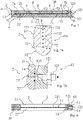
- the pressing plane surface 2 provided with the plurality of ducts 70 can be formed in a single piece, or it can comprises multiple layers, as illustrated in the enclosed figures ( figures 2 , 6 , 7 and 8 ).
- the pressing plane surface comprises a first layer 21, in which the secondary ducts 72 and at least part of the main ducts 71 are obtained, and a second layer 22 with substantially constant thickness.
- the press comprises suitable tightening means 10, for tightening together the layers 21 and 22 of the pressing plane surface 2.
- such tightening means 10 e.g. screws or bolts with configuration adapted for such purpose, are applied to the layers 21 and 22 in proximity to the plurality of ducts 70, arranged on opposite sides with respect to each secondary duct 72, in respective openings obtained if necessary, in order to allow the fluid-tight seal of the ducts themselves and of the main duct 71.
- the press also comprises fluid-tight sealing means 11 between the first layer 21 and the second layer 22, for example a gasket or a layer 111 made of silicone or any other suitable material, applied externally with respect to the layers 21 and 22 at the junction thereof.
- fluid-tight sealing means 11 between the first layer 21 and the second layer 22, for example a gasket or a layer 111 made of silicone or any other suitable material, applied externally with respect to the layers 21 and 22 at the junction thereof.
- the press comprises at least one connecting block 12, fastened to the second face 6 of the pressing plane surface 2 for connection to the suction means of the press.
- Such block 12 comprises at least one support 121 in which a through portion 122 is obtained for each second opening 9 made in the second face 6 of the pressing plane surface 2.
- Each through portion 122, once the block has been fastened to the plane pressing surface 2, is aligned with a respective second opening 9.
- the connecting block 12 also comprises a connecting sleeve 123 for each through portion 122.
- Each connecting sleeve 123 is inserted in the respective through portion 122 and serves as a component of connection with the suction means.
- the connecting block 12 is fastened, e.g. bolted to the second face 6 of the pressing plane surface 2, by means of suitable fastening means 13. Also in this case, in order to facilitate the fluid-tight seal, it is provided that such fastening means 13 are applied in proximity to the through sections 122, arranged on opposite sides with respect to each of these.
- the press also comprises fluid-tight sealing means 14, for example a gasket of a type suitable for this purpose, between the connecting block 12 and the second face 6 of the pressing plane surface 2, in particular around the mouth of each through portion 122 and the second opening 9.
- fluid-tight sealing means 14 for example a gasket of a type suitable for this purpose
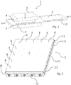
- the press comprises feeding means 15, provided to feed the mass 4 of powder ceramic material to be compacted between the two pressing plane surfaces 2 and 3.
- the feeding means 15 are comprised between the first pressing plane surface 2 and the second pressing plane surface 3, they are positioned on the first pressing plane surface 2, and cross through the forming seat of the press.
- Such feeding means 15, according to the present invention comprise a conveyor belt made of material permeable to gas, e.g. a conveyor belt made of porous fabric.
- the feeding means 15 serve as first filtering element for the powder material to be compacted, since they retain the ceramic powder fraction of larger size, while the finer powder fraction is conveyed towards the pressing plane surface 2, and hence they prevent the manifold circuit from being obstructed.
- One such belt 15 is perforated or micro-perforated, with through holes or micro-holes, so as to be permeable to gas, but impermeable to the powders of materials to be pressed, e.g. to the powders of ceramic materials.
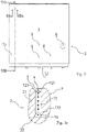
- the belt 15 comprises a distribution or percentage or density of the perforations or micro-perforations with respect to the surface of the belt itself that varies in passing from the center or center line or longitudinal symmetry axis x-x of the belt 15 to the sides S1, S2 thereof and more particularly which decreases in passing from the center or center line or longitudinal symmetry axis x-x of the belt 15 to the sides S1, S2 thereof.
- the belt 15 could have a first zone or central zone or zone 15a developing side to side with respect to the center line x-x of the belt with a first percentage or density of perforations greater than the other zones.
- the belt 15 could have two second zones or intermediate zones 15b, each with a second percentage or density of perforations, and such intermediate zones 15b are side-by-side the central zone 15a and placed on opposite sides from each other with respect to the central zone 15 along with, if desired, two third zones or lateral zones 15c each with a third percentage or density of perforations, and such lateral zones 15c each define a respective side S1, S2 of the belt 15 and are distal from the central zone 15a and each are also side-by-side a respective intermediate zone 15b.
- the first percentage of perforations can be higher than the second percentage of perforations and the second percentage of perforations can be higher than the third percentage of perforations, so that the micro-perforations have denser distribution in the pressing zones that are more internal or further away from the sides S1, S2 of the belt and progressively lower density in approaching the sides S1, S2 of the belt 15.
- the distance between the holes or micro-holes in the central zone 15a could be between about one-fourth and about three-fourths, e.g. between about one-third and about two-thirds the distance of the holes or micro-holes in the intermediate zones 15b, if desired substantially equal to half the distance of the holes or micro-holes in the intermediate zones 15b.
- the distance between the holes or micro-holes in the intermediate zones 15b could be between about one-fourth and about three-fourths, e.g. between about one-third and about two-thirds the distance of the holes or micro-holes in the lateral zones 15c, if desired substantially equal to half the distance of the holes or micro-holes in the lateral zones 15c.
- the holes in the central zone 15a could be spaced from each other by about 2-8 mm, e.g. 3-7 mm, if desired about 5 mm
- the holes in the intermediate zones 15b could be spaced from each other by about 5-15 mm, e.g. 8-12 mm, if desired about 10 mm
- the holes in the lateral zones 15c could be spaced from each other by about 15-25 mm, e.g. 18-22 mm, if desired about 20 mm.
- the central zone 15a has extension transverse or orthogonal to the longitudinal symmetry axis x-x between 0.5 and 2 times, e.g. substantially equal to, the transverse extension of the intermediate zones 15b and, if provided, of the lateral zones 15c.
- the holes are substantially distributed along the entire longitudinal extension (parallel to the axis or center line x-x) and transverse extension (orthogonal to the axis x-x) of the zones 15a, 15b and (if provided) 15c of the belt 15.
- the pressing occurs in a more intense manner at the center line or at the central zone of the belt, while the intensity or power of the pressing decreases in moving away from the center line x-x and in approaching the sides of the belt 15.
- the decrease of percentage of the perforations as indicated above ensures that the suction of the gases from the pressing zone is more greatly ensured where the pressing is greater, simultaneously reducing the costs of perforation or micro-perforation of the belt 15.
- the belt 15 can be obtained by perforating, e.g. by means of water jet, a belt lacking holes, e.g. made of rubber or of a similar material. Such perforation can be made by means of a punch or a group of punches.
- the holes or micro-holes delimited by the or on the belt 15 could have a diameter of about 0.5-3 mm; in an embodiment of the invention, the holes or micro-holes delimited by the, or on, the belt 15 could have a diameter between 0.5 and 1 mm, if desired 0.8 mm.
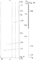
- the belt 15 can be made of multiple layers, for example with a layer, lower during use, reinforced with canvas 15d and an upper layer 15e made of PVC, polyurethane, rubber or a similar material packed with the lower layer 15d.
- the lower layer 15d can be such to facilitate the evacuation of the gases from the pressing zone and to improve the flow on the first pressing plane surface 2.
- the surface of the belt can also have reliefs, and not be smooth.
- the belt 15 could then have terminal connector components 15f, each connected to the lower layer 15d and to the upper layer 15e.
- the belt or a section thereof has two terminal connector components 15f, each at a respective end of the belt section, and such terminal connector components 15f delimit a seat 15g, which if desired is extended transverse or orthogonal to the axis x-x, set to house a hinge or junction with another belt section or with a component for the connection (not illustrated in the figures) with another connector component.
- the connector components 15f could have a width greater than the lower layers 15d and upper layers 15e, so as to project laterally with respect thereto.
- the connector components 15f could also have sectioned or smoothed edges 15f1. Such expedient ensures an improved evacuation of air during the pressing.
- FIG. 11 Another pressing plane surface 2, 3 for a press according to the present invention is illustrated.
- This comprises a base or top plate 16 on which a plurality of side-by-side packed strips 17 are arranged and fastened, in particular removably, so as to define the first face 5 or the second face 6.
- one or more slits or grooves or micro-slits 18 connectable with suitable suction means is/are delimited between at least two adjacent strips 17, preferably between all the pairs of adjacent strips, or in at least one strip 17, preferably in all the strips 17, and such slits or grooves are actually in substitution of the openings 8.
- the strips 17 define the first face 5 facing towards the mass 4 of ceramic material to be compacted or the second face 6.
- the strips 17 can have a first lateral wall 17a with a plurality of notches such to delimit the slits or grooves or micro-slits 18 with the second lateral wall 17b of an adjacent strip, clearly once the strips 17 are packed.
- the slits or grooves or micro-slits 18 can be made within the body of the strips 17.
- the slits or grooves or micro-slits 18 lead, in particular below if they are part of a first pressing plane surface 2 or above if they are part of a second pressing plane surface 2, into one or more suction manifolds or channels 19 in fluid communication with the suction plant, e.g. a vacuum pump.
- the or each suction manifold or channel 19 can be made in the base plate 16 or in the strips 17.
- the manifold(s) 19 can be extended in a direction orthogonal to the front F - rear R direction.
- each strip 17 comprises two lateral walls 17a, 17b, e.g. substantially extended in the front F - rear R direction, an upper wall 17c, a lower wall 17d, a front wall or wall facing towards the front F of the pressing plane surface 2, 3 and a rear wall or wall facing towards the rear R of the pressing plane surface 2, 3.
- the plurality of side-by-side upper walls 17c defines the first face 5, while the plurality of side-by-side lower walls 17d defines the second face 6.
- One of the lateral walls 17a, 17b can be configured substantially as an L in cross section, i.e. in a plane surface orthogonal to the direction from the front F to the rear R of the pressing plane surface 2, 3, so that each strip 17 has a part, lower 17h during use or upper during use of smaller width and a part, upper 17g during use or lower during use of greater width and with a portion 17n projecting with respect to the underlying lower part 17h or overlying upper part.
- a connector chamber 17m is defined between two adjacent strips 17 that is set to place the slits or grooves or micro-slits 18 in fluid communication with a respective suction manifold or channel 19.
- the projecting portion 17n of a strip can have a curved or substantially curved surface 17p delimiting the connector chamber 17m with a portion of lateral wall 17b of an adjacent strip.
- the slits or grooves 18 can be constituted by means of through notches defined at one of the lateral walls 17a, 17b, and additionally the slits or grooves or micro-slits 18 can be extended from the upper face of the first pressing plane surface 2 or lower face of the second pressing plane surface 3 to a suction manifold 19 or, if provided, to a connector chamber 17m leading into a suction manifold 19.
- each strip 17 has a plurality of slits or grooves 18 spaced from each other and, if desired, extended in a direction substantially parallel to the front F - rear R direction. More particularly, each strip has slits or grooves 18 over the entire longitudinal extension thereof or in front F - rear R direction.
- the strips 17 can be fastened, in particular removably, to the base plate 16 by means of fastening means, such as screws, bolts or stops or lateral stop plates 20a and possibly one or more stops or central stop plates 20b, in particular if the pressing plane surface 2, 3 is very long.
- the stops 20a can include a bracket or bar, for example delimiting a through hole, and in such case once the strips 17 are arranged substantially aligned and packed on a base plate 16, a first bracket or bar 20a is arranged above or below the front ends of the strips 17 and a second bracket or bar 20b is arranged above or below the rear ends of the strips 17 and the brackets 20a, 20b are constrained to the base plate by means of screws 20c or the like.
- each manifold circuit 7 is defined by a slit or groove 17 and, if provided, by a connector chamber 17m.
- the air present in the powder material to be compacted can in fact escape outward from the material itself during the pressing process, i.e. when this material is placed under pressure by the pressing plane surfaces 2 and 3 suitably controlled by the power members, according to three preferred pathways.
- the air exits outward from the perimeter edge of the mass of powder ceramic material to be compacted. It exits outward from the conveyor belt, which is permeable to gas, both laterally and through the thickness of the belt towards the underlying pressing plane surface 2, and it also exits outward from the pressing plane surface (2 in the drawings) in fluid connection, by means of the plurality of ducts obtained therein, with suitable suction means.
- the particular configuration of the plurality of ducts 70 facilitates the outward exit of air from the mass of powder material to be compacted, in a manner that is entirely uniform with respect to the mass itself, reducing the risk of stagnation of air in the product, and in a rather reduced time with respect to the time required by the conventional presses. There is therefore an increase of the quality of the obtained products and a reduction of the production times, with increased production efficiency of the press.
- the present invention is applied to presses where only one pressing plane surface is movable with respect to the other (e.g. the one that is lower during use or that upper during use - the latter case is illustrated in the enclosed figures) or to the case in which both pressing plane surfaces are movable.
- pressing plane surface 2 lower during use, is described; here the plurality of ducts 70 is attained but it remains intended that also or only pressing plane surface 3, upper during use, can have the same configuration and be connectable to suitable suction means.
- all three sections 721, 722 and 723 could have substantially circular cross section of equal diameter.
Landscapes
- Engineering & Computer Science (AREA)
- Mechanical Engineering (AREA)
- Manufacturing & Machinery (AREA)
- Chemical & Material Sciences (AREA)
- Ceramic Engineering (AREA)
- Press-Shaping Or Shaping Using Conveyers (AREA)
Applications Claiming Priority (2)
| Application Number | Priority Date | Filing Date | Title |
|---|---|---|---|
| ITUA2016A001432A ITUA20161432A1 (it) | 2016-03-07 | 2016-03-07 | Pressa per la realizzazione di prodotti ceramici |
| PCT/IB2017/051331 WO2017153913A1 (en) | 2016-03-07 | 2017-03-07 | A press for the production of ceramic products |
Publications (2)
| Publication Number | Publication Date |
|---|---|
| EP3426451A1 EP3426451A1 (en) | 2019-01-16 |
| EP3426451B1 true EP3426451B1 (en) | 2022-08-17 |
Family
ID=56203551
Family Applications (1)
| Application Number | Title | Priority Date | Filing Date |
|---|---|---|---|
| EP17719907.2A Active EP3426451B1 (en) | 2016-03-07 | 2017-03-07 | A press for the production of ceramic products |
Country Status (5)
| Country | Link |
|---|---|
| EP (1) | EP3426451B1 (it) |
| CN (1) | CN108698251A (it) |
| BR (1) | BR112018015078A2 (it) |
| IT (1) | ITUA20161432A1 (it) |
| WO (1) | WO2017153913A1 (it) |
Families Citing this family (1)
| Publication number | Priority date | Publication date | Assignee | Title |
|---|---|---|---|---|
| CN114643634B (zh) * | 2022-03-22 | 2022-11-29 | 重庆臻宝实业有限公司 | 一种注浆成型的真空模具 |
Citations (1)
| Publication number | Priority date | Publication date | Assignee | Title |
|---|---|---|---|---|
| ITMO20100268A1 (it) * | 2010-09-27 | 2012-03-28 | Gambarelli Impianti S R L | Apparato per la formatura di manufatti sostanzialmente lastriformi. |
Family Cites Families (11)
| Publication number | Priority date | Publication date | Assignee | Title |
|---|---|---|---|---|
| US3737276A (en) * | 1971-09-17 | 1973-06-05 | Carborundum Co | Molding of powdered or granular material |
| FR2673566B3 (fr) * | 1991-03-08 | 1993-01-15 | Voinchet Jean Marie | Dispositif pour la realisation des preformes necessaires au moulage en pate des ceramiques. |
| IT1269274B (it) * | 1994-11-22 | 1997-03-26 | Carlo Antonio Camorani | Metodo per la formatura di piastrelle ceramiche ed impianto relativo |
| EP0995563A1 (en) * | 1998-10-15 | 2000-04-26 | Ronflette S.A. | A plant and process for forming ceramic products, such as tiles and the like, by powder pressing |
| CN2477339Y (zh) * | 2001-07-19 | 2002-02-20 | 佛山市石湾镇陶瓷工业研究所 | 陶瓷砖排气冲模 |
| US8353591B2 (en) * | 2006-04-20 | 2013-01-15 | Kabushiki Kaisha Isowa | Apparatus and method for printing corrugated cardboard sheets |
| IT1401322B1 (it) * | 2010-03-10 | 2013-07-18 | Gape Due S P A | Stampo per la pressatura unidirezionale di manufatti ceramici |
| EP2384870A1 (en) * | 2010-05-04 | 2011-11-09 | Officina Ferrari Carlo Societa' Per Azioni | A die for forming ceramic tiles provided with automatic air expulsion |
| WO2012143960A1 (en) * | 2011-04-22 | 2012-10-26 | Vecor Ip Holdings Ltd | Apparatuses, system and methods for forming pressed articles and pressed articles formed thereby |
| FR3000530B1 (fr) * | 2012-12-28 | 2015-07-10 | Bobst Lyon | Bande de transport d’elements en plaques et machine de transformation comprenant une telle bande de transport |
| CN203331202U (zh) * | 2013-06-28 | 2013-12-11 | 周文鹏 | 活动顶针式陶瓷砖成型排气模具的模芯底板 |
-
2016
- 2016-03-07 IT ITUA2016A001432A patent/ITUA20161432A1/it unknown
-
2017
- 2017-03-07 WO PCT/IB2017/051331 patent/WO2017153913A1/en active Application Filing
- 2017-03-07 BR BR112018015078A patent/BR112018015078A2/pt not_active Application Discontinuation
- 2017-03-07 EP EP17719907.2A patent/EP3426451B1/en active Active
- 2017-03-07 CN CN201780007938.8A patent/CN108698251A/zh active Pending
Patent Citations (1)
| Publication number | Priority date | Publication date | Assignee | Title |
|---|---|---|---|---|
| ITMO20100268A1 (it) * | 2010-09-27 | 2012-03-28 | Gambarelli Impianti S R L | Apparato per la formatura di manufatti sostanzialmente lastriformi. |
Also Published As
| Publication number | Publication date |
|---|---|
| EP3426451A1 (en) | 2019-01-16 |
| ITUA20161432A1 (it) | 2017-09-07 |
| WO2017153913A1 (en) | 2017-09-14 |
| BR112018015078A2 (pt) | 2018-12-11 |
| CN108698251A (zh) | 2018-10-23 |
Similar Documents
| Publication | Publication Date | Title |
|---|---|---|
| CN1205015C (zh) | 多通道冷却模 | |
| EP3426451B1 (en) | A press for the production of ceramic products | |
| KR20160125365A (ko) | 저마찰 표면들을 사용하여 건축용 판재를 구성하기 위한 장치 및 방법 | |
| US20160096305A1 (en) | Die Assembly And Method Of Extruding Cellular Ceramic Substrates With A Skin | |
| CA1140716A (en) | Extruding die apparatus for producing a plastic closure strip | |
| KR102295938B1 (ko) | 공압식 폐지 제거장치가 구비된 톰슨 금형장치 | |
| GB2041030A (en) | Compound Paper | |
| IL146866A (en) | Device for handling sheet materials using pressurized water jets | |
| CN217089467U (zh) | 一种全自动豆制品加工装置 | |
| DE1953816A1 (de) | Verfahren und Einrichtung zur Herstellung von ein- und mehrschichtigen Spanplatten und zu deren Beschichtung | |
| CN104070762B (zh) | 异种面料粘合机 | |
| GB1075249A (en) | Production of ribbed building board or the like | |
| US3535190A (en) | Apparatus for making honeycomb structures | |
| US10596721B2 (en) | Apparatus and method of manufacturing ceramic honeycomb body | |
| CN210475684U (zh) | 一种钢带增强管切割装置 | |
| CN210473170U (zh) | 一种改进型压滤机滤板 | |
| ITMO20100268A1 (it) | Apparato per la formatura di manufatti sostanzialmente lastriformi. | |
| CN204777942U (zh) | 连续化生产设备 | |
| JPS57150410A (en) | Pressurized dehydrating method | |
| KR20010023155A (ko) | 파티클 보오드 매트 형성 방법 및 장치 | |
| CN216658359U (zh) | 一种辊及压制机构及制造装置 | |
| CN214111566U (zh) | 一种改进型口罩带焊接装置 | |
| CN215026315U (zh) | 一种反吹除水压滤机滤板 | |
| CN209236875U (zh) | 膏药滴注成型上料装置 | |
| CN209158586U (zh) | 一种防进料褶皱的模切机进料机构 |
Legal Events
| Date | Code | Title | Description |
|---|---|---|---|
| STAA | Information on the status of an ep patent application or granted ep patent |
Free format text: STATUS: UNKNOWN |
|
| STAA | Information on the status of an ep patent application or granted ep patent |
Free format text: STATUS: THE INTERNATIONAL PUBLICATION HAS BEEN MADE |
|
| PUAI | Public reference made under article 153(3) epc to a published international application that has entered the european phase |
Free format text: ORIGINAL CODE: 0009012 |
|
| STAA | Information on the status of an ep patent application or granted ep patent |
Free format text: STATUS: REQUEST FOR EXAMINATION WAS MADE |
|
| 17P | Request for examination filed |
Effective date: 20180625 |
|
| AK | Designated contracting states |
Kind code of ref document: A1 Designated state(s): AL AT BE BG CH CY CZ DE DK EE ES FI FR GB GR HR HU IE IS IT LI LT LU LV MC MK MT NL NO PL PT RO RS SE SI SK SM TR |
|
| AX | Request for extension of the european patent |
Extension state: BA ME |
|
| DAV | Request for validation of the european patent (deleted) | ||
| DAX | Request for extension of the european patent (deleted) | ||
| STAA | Information on the status of an ep patent application or granted ep patent |
Free format text: STATUS: EXAMINATION IS IN PROGRESS |
|
| 17Q | First examination report despatched |
Effective date: 20191001 |
|
| STAA | Information on the status of an ep patent application or granted ep patent |
Free format text: STATUS: EXAMINATION IS IN PROGRESS |
|
| STAA | Information on the status of an ep patent application or granted ep patent |
Free format text: STATUS: EXAMINATION IS IN PROGRESS |
|
| RIC1 | Information provided on ipc code assigned before grant |
Ipc: B30B 15/02 20060101ALI20220120BHEP Ipc: B30B 15/00 20060101ALI20220120BHEP Ipc: B28B 7/44 20060101ALI20220120BHEP Ipc: B28B 7/00 20060101ALI20220120BHEP Ipc: B28B 5/02 20060101ALI20220120BHEP Ipc: B28B 3/02 20060101AFI20220120BHEP |
|
| GRAP | Despatch of communication of intention to grant a patent |
Free format text: ORIGINAL CODE: EPIDOSNIGR1 |
|
| STAA | Information on the status of an ep patent application or granted ep patent |
Free format text: STATUS: GRANT OF PATENT IS INTENDED |
|
| INTG | Intention to grant announced |
Effective date: 20220317 |
|
| GRAS | Grant fee paid |
Free format text: ORIGINAL CODE: EPIDOSNIGR3 |
|
| GRAA | (expected) grant |
Free format text: ORIGINAL CODE: 0009210 |
|
| STAA | Information on the status of an ep patent application or granted ep patent |
Free format text: STATUS: THE PATENT HAS BEEN GRANTED |
|
| AK | Designated contracting states |
Kind code of ref document: B1 Designated state(s): AL AT BE BG CH CY CZ DE DK EE ES FI FR GB GR HR HU IE IS IT LI LT LU LV MC MK MT NL NO PL PT RO RS SE SI SK SM TR |
|
| REG | Reference to a national code |
Ref country code: CH Ref legal event code: EP |
|
| REG | Reference to a national code |
Ref country code: DE Ref legal event code: R096 Ref document number: 602017060729 Country of ref document: DE |
|
| REG | Reference to a national code |
Ref country code: IE Ref legal event code: FG4D |
|
| REG | Reference to a national code |
Ref country code: AT Ref legal event code: REF Ref document number: 1511889 Country of ref document: AT Kind code of ref document: T Effective date: 20220915 |
|
| REG | Reference to a national code |
Ref country code: NL Ref legal event code: MP Effective date: 20220817 |
|
| REG | Reference to a national code |
Ref country code: LT Ref legal event code: MG9D |
|
| PG25 | Lapsed in a contracting state [announced via postgrant information from national office to epo] |
Ref country code: SE Free format text: LAPSE BECAUSE OF FAILURE TO SUBMIT A TRANSLATION OF THE DESCRIPTION OR TO PAY THE FEE WITHIN THE PRESCRIBED TIME-LIMIT Effective date: 20220817 Ref country code: RS Free format text: LAPSE BECAUSE OF FAILURE TO SUBMIT A TRANSLATION OF THE DESCRIPTION OR TO PAY THE FEE WITHIN THE PRESCRIBED TIME-LIMIT Effective date: 20220817 Ref country code: PT Free format text: LAPSE BECAUSE OF FAILURE TO SUBMIT A TRANSLATION OF THE DESCRIPTION OR TO PAY THE FEE WITHIN THE PRESCRIBED TIME-LIMIT Effective date: 20221219 Ref country code: NO Free format text: LAPSE BECAUSE OF FAILURE TO SUBMIT A TRANSLATION OF THE DESCRIPTION OR TO PAY THE FEE WITHIN THE PRESCRIBED TIME-LIMIT Effective date: 20221117 Ref country code: NL Free format text: LAPSE BECAUSE OF FAILURE TO SUBMIT A TRANSLATION OF THE DESCRIPTION OR TO PAY THE FEE WITHIN THE PRESCRIBED TIME-LIMIT Effective date: 20220817 Ref country code: LV Free format text: LAPSE BECAUSE OF FAILURE TO SUBMIT A TRANSLATION OF THE DESCRIPTION OR TO PAY THE FEE WITHIN THE PRESCRIBED TIME-LIMIT Effective date: 20220817 Ref country code: LT Free format text: LAPSE BECAUSE OF FAILURE TO SUBMIT A TRANSLATION OF THE DESCRIPTION OR TO PAY THE FEE WITHIN THE PRESCRIBED TIME-LIMIT Effective date: 20220817 Ref country code: FI Free format text: LAPSE BECAUSE OF FAILURE TO SUBMIT A TRANSLATION OF THE DESCRIPTION OR TO PAY THE FEE WITHIN THE PRESCRIBED TIME-LIMIT Effective date: 20220817 |
|
| REG | Reference to a national code |
Ref country code: AT Ref legal event code: MK05 Ref document number: 1511889 Country of ref document: AT Kind code of ref document: T Effective date: 20220817 |
|
| PG25 | Lapsed in a contracting state [announced via postgrant information from national office to epo] |
Ref country code: PL Free format text: LAPSE BECAUSE OF FAILURE TO SUBMIT A TRANSLATION OF THE DESCRIPTION OR TO PAY THE FEE WITHIN THE PRESCRIBED TIME-LIMIT Effective date: 20220817 Ref country code: IS Free format text: LAPSE BECAUSE OF FAILURE TO SUBMIT A TRANSLATION OF THE DESCRIPTION OR TO PAY THE FEE WITHIN THE PRESCRIBED TIME-LIMIT Effective date: 20221217 Ref country code: HR Free format text: LAPSE BECAUSE OF FAILURE TO SUBMIT A TRANSLATION OF THE DESCRIPTION OR TO PAY THE FEE WITHIN THE PRESCRIBED TIME-LIMIT Effective date: 20220817 Ref country code: GR Free format text: LAPSE BECAUSE OF FAILURE TO SUBMIT A TRANSLATION OF THE DESCRIPTION OR TO PAY THE FEE WITHIN THE PRESCRIBED TIME-LIMIT Effective date: 20221118 |
|
| PG25 | Lapsed in a contracting state [announced via postgrant information from national office to epo] |
Ref country code: SM Free format text: LAPSE BECAUSE OF FAILURE TO SUBMIT A TRANSLATION OF THE DESCRIPTION OR TO PAY THE FEE WITHIN THE PRESCRIBED TIME-LIMIT Effective date: 20220817 Ref country code: RO Free format text: LAPSE BECAUSE OF FAILURE TO SUBMIT A TRANSLATION OF THE DESCRIPTION OR TO PAY THE FEE WITHIN THE PRESCRIBED TIME-LIMIT Effective date: 20220817 Ref country code: ES Free format text: LAPSE BECAUSE OF FAILURE TO SUBMIT A TRANSLATION OF THE DESCRIPTION OR TO PAY THE FEE WITHIN THE PRESCRIBED TIME-LIMIT Effective date: 20220817 Ref country code: DK Free format text: LAPSE BECAUSE OF FAILURE TO SUBMIT A TRANSLATION OF THE DESCRIPTION OR TO PAY THE FEE WITHIN THE PRESCRIBED TIME-LIMIT Effective date: 20220817 Ref country code: CZ Free format text: LAPSE BECAUSE OF FAILURE TO SUBMIT A TRANSLATION OF THE DESCRIPTION OR TO PAY THE FEE WITHIN THE PRESCRIBED TIME-LIMIT Effective date: 20220817 Ref country code: AT Free format text: LAPSE BECAUSE OF FAILURE TO SUBMIT A TRANSLATION OF THE DESCRIPTION OR TO PAY THE FEE WITHIN THE PRESCRIBED TIME-LIMIT Effective date: 20220817 |
|
| REG | Reference to a national code |
Ref country code: DE Ref legal event code: R097 Ref document number: 602017060729 Country of ref document: DE |
|
| PG25 | Lapsed in a contracting state [announced via postgrant information from national office to epo] |
Ref country code: SK Free format text: LAPSE BECAUSE OF FAILURE TO SUBMIT A TRANSLATION OF THE DESCRIPTION OR TO PAY THE FEE WITHIN THE PRESCRIBED TIME-LIMIT Effective date: 20220817 Ref country code: EE Free format text: LAPSE BECAUSE OF FAILURE TO SUBMIT A TRANSLATION OF THE DESCRIPTION OR TO PAY THE FEE WITHIN THE PRESCRIBED TIME-LIMIT Effective date: 20220817 |
|
| PLBE | No opposition filed within time limit |
Free format text: ORIGINAL CODE: 0009261 |
|
| STAA | Information on the status of an ep patent application or granted ep patent |
Free format text: STATUS: NO OPPOSITION FILED WITHIN TIME LIMIT |
|
| PG25 | Lapsed in a contracting state [announced via postgrant information from national office to epo] |
Ref country code: AL Free format text: LAPSE BECAUSE OF FAILURE TO SUBMIT A TRANSLATION OF THE DESCRIPTION OR TO PAY THE FEE WITHIN THE PRESCRIBED TIME-LIMIT Effective date: 20220817 |
|
| 26N | No opposition filed |
Effective date: 20230519 |
|
| PG25 | Lapsed in a contracting state [announced via postgrant information from national office to epo] |
Ref country code: SI Free format text: LAPSE BECAUSE OF FAILURE TO SUBMIT A TRANSLATION OF THE DESCRIPTION OR TO PAY THE FEE WITHIN THE PRESCRIBED TIME-LIMIT Effective date: 20220817 |
|
| REG | Reference to a national code |
Ref country code: DE Ref legal event code: R119 Ref document number: 602017060729 Country of ref document: DE |
|
| PG25 | Lapsed in a contracting state [announced via postgrant information from national office to epo] |
Ref country code: MC Free format text: LAPSE BECAUSE OF FAILURE TO SUBMIT A TRANSLATION OF THE DESCRIPTION OR TO PAY THE FEE WITHIN THE PRESCRIBED TIME-LIMIT Effective date: 20220817 |
|
| REG | Reference to a national code |
Ref country code: CH Ref legal event code: PL |
|
| GBPC | Gb: european patent ceased through non-payment of renewal fee |
Effective date: 20230307 |
|
| REG | Reference to a national code |
Ref country code: BE Ref legal event code: MM Effective date: 20230331 |
|
| PG25 | Lapsed in a contracting state [announced via postgrant information from national office to epo] |
Ref country code: LU Free format text: LAPSE BECAUSE OF NON-PAYMENT OF DUE FEES Effective date: 20230307 |
|
| REG | Reference to a national code |
Ref country code: IE Ref legal event code: MM4A |
|
| PG25 | Lapsed in a contracting state [announced via postgrant information from national office to epo] |
Ref country code: GB Free format text: LAPSE BECAUSE OF NON-PAYMENT OF DUE FEES Effective date: 20230307 |
|
| PG25 | Lapsed in a contracting state [announced via postgrant information from national office to epo] |
Ref country code: LI Free format text: LAPSE BECAUSE OF NON-PAYMENT OF DUE FEES Effective date: 20230331 Ref country code: IE Free format text: LAPSE BECAUSE OF NON-PAYMENT OF DUE FEES Effective date: 20230307 Ref country code: GB Free format text: LAPSE BECAUSE OF NON-PAYMENT OF DUE FEES Effective date: 20230307 Ref country code: FR Free format text: LAPSE BECAUSE OF NON-PAYMENT OF DUE FEES Effective date: 20230331 Ref country code: DE Free format text: LAPSE BECAUSE OF NON-PAYMENT OF DUE FEES Effective date: 20231003 Ref country code: CH Free format text: LAPSE BECAUSE OF NON-PAYMENT OF DUE FEES Effective date: 20230331 |
|
| PG25 | Lapsed in a contracting state [announced via postgrant information from national office to epo] |
Ref country code: BE Free format text: LAPSE BECAUSE OF NON-PAYMENT OF DUE FEES Effective date: 20230331 |