EP3426331B1 - Lenkbarer katheter mit mehreren krümmungsradien über einen lenkmechanismus mit teleskopischen rohrförmigen komponenten - Google Patents
Lenkbarer katheter mit mehreren krümmungsradien über einen lenkmechanismus mit teleskopischen rohrförmigen komponenten Download PDFInfo
- Publication number
- EP3426331B1 EP3426331B1 EP17711533.4A EP17711533A EP3426331B1 EP 3426331 B1 EP3426331 B1 EP 3426331B1 EP 17711533 A EP17711533 A EP 17711533A EP 3426331 B1 EP3426331 B1 EP 3426331B1
- Authority
- EP
- European Patent Office
- Prior art keywords
- tubular sheath
- catheter
- distal
- anchor point
- distal end
- Prior art date
- Legal status (The legal status is an assumption and is not a legal conclusion. Google has not performed a legal analysis and makes no representation as to the accuracy of the status listed.)
- Active
Links
Images


Classifications
-
- A—HUMAN NECESSITIES
- A61—MEDICAL OR VETERINARY SCIENCE; HYGIENE
- A61F—FILTERS IMPLANTABLE INTO BLOOD VESSELS; PROSTHESES; DEVICES PROVIDING PATENCY TO, OR PREVENTING COLLAPSING OF, TUBULAR STRUCTURES OF THE BODY, e.g. STENTS; ORTHOPAEDIC, NURSING OR CONTRACEPTIVE DEVICES; FOMENTATION; TREATMENT OR PROTECTION OF EYES OR EARS; BANDAGES, DRESSINGS OR ABSORBENT PADS; FIRST-AID KITS
- A61F2/00—Filters implantable into blood vessels; Prostheses, i.e. artificial substitutes or replacements for parts of the body; Appliances for connecting them with the body; Devices providing patency to, or preventing collapsing of, tubular structures of the body, e.g. stents
- A61F2/95—Instruments specially adapted for placement or removal of stents or stent-grafts
- A61F2/962—Instruments specially adapted for placement or removal of stents or stent-grafts having an outer sleeve
- A61F2/966—Instruments specially adapted for placement or removal of stents or stent-grafts having an outer sleeve with relative longitudinal movement between outer sleeve and prosthesis, e.g. using a push rod
-
- A—HUMAN NECESSITIES
- A61—MEDICAL OR VETERINARY SCIENCE; HYGIENE
- A61M—DEVICES FOR INTRODUCING MEDIA INTO, OR ONTO, THE BODY; DEVICES FOR TRANSDUCING BODY MEDIA OR FOR TAKING MEDIA FROM THE BODY; DEVICES FOR PRODUCING OR ENDING SLEEP OR STUPOR
- A61M25/00—Catheters; Hollow probes
- A61M25/01—Introducing, guiding, advancing, emplacing or holding catheters
- A61M25/0105—Steering means as part of the catheter or advancing means; Markers for positioning
- A61M25/0133—Tip steering devices
- A61M25/0147—Tip steering devices with movable mechanical means, e.g. pull wires
- A61M2025/015—Details of the distal fixation of the movable mechanical means
-
- A—HUMAN NECESSITIES
- A61—MEDICAL OR VETERINARY SCIENCE; HYGIENE
- A61M—DEVICES FOR INTRODUCING MEDIA INTO, OR ONTO, THE BODY; DEVICES FOR TRANSDUCING BODY MEDIA OR FOR TAKING MEDIA FROM THE BODY; DEVICES FOR PRODUCING OR ENDING SLEEP OR STUPOR
- A61M25/00—Catheters; Hollow probes
- A61M25/01—Introducing, guiding, advancing, emplacing or holding catheters
- A61M2025/0175—Introducing, guiding, advancing, emplacing or holding catheters having telescopic features, interengaging nestable members movable in relations to one another
-
- A—HUMAN NECESSITIES
- A61—MEDICAL OR VETERINARY SCIENCE; HYGIENE
- A61M—DEVICES FOR INTRODUCING MEDIA INTO, OR ONTO, THE BODY; DEVICES FOR TRANSDUCING BODY MEDIA OR FOR TAKING MEDIA FROM THE BODY; DEVICES FOR PRODUCING OR ENDING SLEEP OR STUPOR
- A61M25/00—Catheters; Hollow probes
- A61M25/01—Introducing, guiding, advancing, emplacing or holding catheters
- A61M25/0105—Steering means as part of the catheter or advancing means; Markers for positioning
- A61M25/0133—Tip steering devices
- A61M25/0136—Handles therefor
Definitions
- the invention relates generally to catheters, and in particular to catheters that may be selectively steered or bent in situ.
- catheters for delivering a therapy and/or monitoring a physiological condition have been implanted or proposed for implantation in patients.
- Catheters may deliver therapy to, and/or monitor conditions associated with, the heart, muscle, nerve, brain, stomach or other organs or tissue.
- Many catheters are tracked through the vasculature to locate a therapeutic or diagnostic portion of the catheter at a target site.
- Such catheters must have flexibility to navigate the twists and turns of the vasculature, sufficient stiffness in the proximal portion thereof to be pushed through the vasculature alone or over a guidewire or through a lumen, and the capability of orienting a distal portion thereof in alignment with an anatomical feature at the target site so that a diagnostic or therapeutic procedure can be completed.
- the catheter body must also resist kinking and be capable of being advanced through access pathways that twist and turn, sometimes abruptly at acute angles.
- a distal opening thereof may be aligned with an ostium of a branch or side vessel.
- the distal portions of catheters frequently need to be selectively curved or bent and straightened again while being advanced within the patient to steer the catheter distal end into a desired body lumen or chamber.
- some procedures require high accuracy in guidewire orientation. For example, often patient's arteries are irregularly shaped, highly tortuous and very narrow. The tortuous configuration of the arteries may present difficulties to a clinician in advancement of a catheter to a treatment site.
- Embodiments hereof relate to a steerable catheter including a tubular sheath having a lumen formed within a wall thereof, and a steering mechanism disposed within the lumen.
- the steering mechanism includes first and second steering components. At least a segment of the second steering component is coaxially disposed within the first steering component. The first steering component and the second steering component are separately tensioned to bend respective regions of the tubular sheath.
- a steerable guide catheter includes a tubular sheath defining a central lumen sized to receive a medical device there-through.
- a longitudinally-extending lumen is formed with a wall of the tubular sheath.
- a pull tube defines a pull wire lumen, the pull tube having a distal end attached at a first anchor point to the tubular sheath and having at least a segment slidably disposed within the longitudinally-extending lumen of the tubular sheath.
- a pull wire has a distal end attached at a second anchor point to the tubular sheath and having at least a segment slidably disposed within the pull wire lumen of the pull tube.
- the second anchor point is distal of the first anchor point.
- the pull tube and the pull wire are separately tensioned to bend respective regions of the tubular sheath.
- a steerable delivery system for a prosthesis includes a tubular sheath defining a central lumen and having a lumen formed within a wall thereof, a pull tube having at least a segment slidably disposed in the lumen within the wall of the tubular sheath, and a pull wire having at least a segment slidably disposed within the pull tube.
- a distal end of the pull tube is attached at a first anchor point to the tubular sheath and a distal end of the pull wire is attached at a second anchor point to the tubular sheath and wherein the second anchor point is distal of the first anchor point.
- the pull tube and the pull wire are separately tensioned to bend respective regions of the tubular sheath.
- distal and proximal are used in the following description with respect to a position or direction relative to the treating clinician.
- distal or disally are a position distant from or in a direction away from the clinician.
- Proximal and “proximally” are a position near or in a direction toward the clinician.
- Embodiments hereof relate to catheters or similar apparatuses having multiple steerable portions that may be selectively and individually bent in situ. More particularly, with reference to FIGS. 1-4 , embodiments hereof relate to a steerable catheter 100 including a tubular component or sheath 102 and a handle 150 coupled to a proximal end 104 of tubular sheath 102 to allow for steering of tubular sheath 102 as described herein. Tubular sheath 102 has a distal end 106 opposite handle 150.
- FIG. 1 and FIG. 3 are side and perspective views, respectively, of steerable catheter 100 in a straight or straightened configuration, while FIG. 2 and FIG.
- steerable catheter 100 in a curved or bent configuration in which a proximal steering region or portion 130 of tubular sheath 102 is curved to a first radius of curvature R 1 and a distal steerable portion 140 of tubular sheath 102 is curved to a second radius of curvature R 2 .
- steerable catheter 100 has a steering mechanism 120 for controllably steering proximal steerable portion 130 of tubular sheath 102 and distal steerable portion 140 of tubular sheath 102.
- Steering mechanism 120 is accessible to a user via handle 150 and is configured to separately or individually bend or deflect proximal and distal steerable portions 130, 140 of tubular sheath 102. Stated another way, proximal and distal steerable portions 130, 140 of tubular sheath 102 are steerable portions of the tubular sheath in that the curvature thereof can be changed based on the user manipulating steering mechanism 120 via handle 150.
- tubular sheath 102 defines a central lumen 108 extending there-through, i.e. , from proximal end 104 to distal end 106 thereof, and a longitudinally-extending lumen 112 is formed with a wall 110 of tubular sheath 102.
- longitudinally-extending lumen 112 is preformed in wall 110 of tubular sheath 102 and may be formed for example by multi-lumen profile extrusion.
- Central lumen 108 is open at distal end 106 of tubular sheath 102 which in turn forms the distal end of steerable catheter 100.
- Longitudinally-extending lumen 112 extends adjacent or parallel to central lumen 108. However, longitudinally-extending lumen 112 does not extend the entire length of tubular sheath 102 but terminates proximal to distal end 106 of tubular sheath 102. Longitudinally-extending lumen 112 houses steering mechanism 120. In an embodiment hereof, as will be explained in more detail herein, central lumen 108 is sized or configured to slidingly receive a medical device such as a guidewire or a treatment catheter there-through when steerable catheter 100 is configured to be an introducer or guide catheter.
- a medical device such as a guidewire or a treatment catheter there-through when steerable catheter 100 is configured to be an introducer or guide catheter.
- central lumen 108 is sized or configured to house an inner shaft component when steerable catheter 100 is configured to be an outer component of a treatment or delivery catheter.
- steerable catheter 100 is a stand-alone catheter while in another embodiment hereof, steerable catheter 100 forms an outer component of medical device such as but not limited to a treatment or delivery catheter.
- wall 110 has a variable thickness such that the thickness of tubular sheath 102 is greater along one side thereof to accommodate longitudinally-extending lumen 112 formed there-through.
- the variable thickness of wall 110 minimizes the overall profile of tubular sheath 102.
- tubular sheath 102 and wall 110 may have other configurations such as but not limited to the configuration shown in FIG. 1B.
- FIG. 1B is a cross-sectional view of a tubular sheath 102B according to another embodiment hereof.
- Tubular sheath 102B defines a central lumen 108B extending there-through and a longitudinally-extending lumen 112B is formed with a wall 110B of tubular sheath 102B.
- Wall 110B has a non-varying or constant thickness, the thickness being sufficient to accommodate longitudinally-extending lumen 112B and steering mechanism 120 coaxially disposed therein.
- longitudinally-extending lumen 112 may have different configurations or shapes.
- longitudinally-extending lumen 112 may have an oval or oblong cross-section and the tubular components of steering mechanism 120, e.g ., pull tube 122 and pull wire 132, may each have an oval or oblong cross-section and a flat or flattened longitudinal profile.
- Steering mechanism 120 is coaxially disposed within longitudinally-extending lumen 112 of tubular sheath 102.
- Steering mechanism 120 includes a first steering component or pull tube 122 and a second steering component or pull wire 132 which is coaxially disposed within a lumen 123 defined by pull tube 122.
- Pull tube 122 may also be considered an exterior tube or tubular component that forms a slidable lumen while pull wire 132 is an interior tube or tubular component slidably disposed within pull tube 122.
- "slidably” denotes back and forth movement in a longitudinal direction along longitudinal axis L A of steering catheter 100.
- Pull wire 132 nests or telescopes within pull tube 122 so that the overall profile of steering catheter 100 is reduced compared to steering components that are disposed parallel to each other.
- pull tube 122 is a hypotube.
- Pull tube 122 and pull wire 132 may be separately controlled or manipulated to cause a particular or respective portion of tubular sheath 102 to bend or curve in a curling motion.
- pull tube 122 and pull wire 132 are primarily housed or disposed within longitudinally-extending lumen 112 of tubular sheath 102, proximal ends 124, 134, respectively, proximally extend beyond proximal end 104 of tubular sheath 102 and are accessible via handle 150 to be pulled or pushed which results in controlled bending movement of the corresponding steerable portion of tubular sheath 102.
- pull tube 122 includes at least a segment slidably disposed within longitudinally-extending lumen 122 of tubular sheath 102.
- Proximal end 124 of pull tube 122 is attached or coupled to a first actuator 152 of handle 150 as shown on FIG. 5 and a distal end 126 of pull tube 122 is attached or coupled to tubular sheath 102 at a first anchor point 128 as shown on FIG. 3 .
- First actuator 152 will be described in more detail below with reference to FIGS. 5 and 6 .
- First anchor point 128 is proximally spaced from distal end 106 of tubular sheath 102 such that tensioning or pulling of pull tube 122 via first actuator 152 bends or curves proximal steerable portion 130 to a first radius of curvature R 1 as shown on FIGS. 2 and 4 .
- the dimension of first radius of curvature R 1 depends upon the intended application of steerable catheter 100, the target anatomy for use of steerable catheter 100, and/or the size or profile of steerable catheter 100. In an embodiment in which steerable catheter 100 is utilized in a TAVI or transcatheter aortic valve implantation procedure, first radius of curvature R 1 ranges between thirty five (35) millimeters and eighty (80) millimeters.
- first radius of curvature R 1 may be as small as 0.5 centimeters.
- Distal end 126 of pull tube 122 is attached or fixed to tubular sheath 102 within longitudinally-extending lumen 122 thereof.
- pull tube 122 is formed from stainless steel and a metal band or ring 129 is utilized to attach distal end 126 of pull tube 122 to tubular sheath 102.
- Distal end 126 of pull tube 122 is attached to metal band 129 by welding.
- pull tube 122 is formed from a relatively hard polymeric material, with high tensile stiffness, and the polymer material of distal end 126 is reflowed in order to attach distal end 126 of pull tube 122 to tubular sheath 102.
- Distal end 126 of pull tube 122 may alternatively be attached to tubular sheath 102 using other conventional techniques, including bonding or adhesive, and it will be understood by one of ordinary skill in the art that the method of attachment depends upon the material of pull tube 122.
- Tubular sheath 102 may be formed of one or more polymeric materials, non-exhaustive examples of which include polyethylene, polyethylene block amide copolymer (PEBA), polyamide and/or combinations thereof, either laminated, blended or co-extruded.
- tubular sheath 102 or some portion thereof may be formed as a composite having a reinforcement layer incorporated within a polymeric body in order to enhance strength and/or flexibility and/or torquability.
- Suitable reinforcement layers include braiding, wire mesh layers, embedded axial wires, embedded helical or circumferential wires, hypotubes, and the like.
- at least a proximal portion of tubular sheath 102 may be formed from a reinforced polymeric tube.
- tubular sheath 102 may include articulated longitudinal sections corresponding to the first and second radii of curvature R 1 , R 2 and the articulated longitudinal sections are formed from different polymers to each other and/or to the main proximal section thereof.
- Pull wire 132 includes at least a segment slidably disposed within lumen 123 of pull tube 122. Proximal end 134 of pull wire 132 is attached or coupled to a second actuator 162 of handle 150 as shown on FIG. 5 and a distal end 136 of pull wire 132 is attached or coupled to tubular sheath 102 at a second anchor point 138 as shown on FIG. 3 . Second actuator 162 will be described in more detail below with reference to FIGS. 5 and 6 . Second anchor point 138 is distal of first anchor point 128.
- second anchor point 138 is at distal end 106 of tubular sheath 102 such that tensioning or pulling of pull wire 132 via second actuator 162 bends or curves distal steerable portion 140 to a second radius of curvature R 2 as shown on FIGS. 2 and 4 .
- the dimension of second radius of curvature R 2 depends upon the intended application of steerable catheter 100, the target anatomy for use of steerable catheter 100, and/or the size or profile of steerable catheter 100. In an embodiment in which steerable catheter 100 is utilized in a TAVI or transcatheter aortic valve implantation procedure, second radius of curvature R 2 ranges between twenty (20) millimeters and sixty (60) millimeters.
- second radius of curvature R 2 may be as small as 0.5 centimeters.
- a distal segment 142 of pull wire 132 extends from distal end 126 of pull tube 122 to second anchor point 138 and is slidably disposed within a corresponding distal portion of longitudinally-extending lumen 112 of tubular sheath 102.
- pull wire 132 is formed from stainless steel and a metal band or ring 139 is utilized to attach distal end 136 of pull wire 132 to tubular sheath 102.
- Distal end 136 of pull wire 132 is attached to metal band 139 by welding.
- pull wire 132 is formed from KEVLAR or another relatively hard polymeric material and the polymer material of distal end 136 is reflowed in order to attach distal end 136 of pull wire 132 to tubular sheath 102.
- Distal end 136 of pull wire 132 may alternatively be attached to tubular sheath 102 using other conventional techniques, including bonding or adhesive, and it will be understood by one of ordinary skill in the art that the method of attachment depends upon the material of pull wire 132.
- Pull wire 132 and pull tube 122 may be formed from different materials and thus the method of attachment for pull wire 132 and pull tube 122 may differ.
- pull tube 122 and pull wire 132 are configured to be separately and individually tensioned to bend or deflect respective steerable regions of tubular sheath 102, namely proximal steerable portion 130 and distal steerable portion 140, respectively.
- Proximal steerable portion 130 is proximal of distal end 126 of pull tube 122 and distal steerable portion 140 is distal of distal end 126 of pull tube 122.
- Tensioning of pull tube 122 bends proximal steerable portion 130 to first radius of curvature R 1
- tensioning of pull wire 132 bends distal steerable portion 140 to second radius of curvature R 2 .
- first and second radii of curvature R 1 , R 2 are different from each other.
- the ability to individually or separately bend two regions of tubular sheath 102 provides a number of advantages.
- steerable catheter 100 may better conform to the anatomy of a heart or vasculature that is encountered during a surgical procedure.
- the distance between first anchor point 128 of pull tube 122 and second anchor point 138 of pull wire 132 depends upon the intended application of steerable catheter 100, the target anatomy for use of steerable catheter 100, and/or the size or profile of steerable catheter 100.
- first anchor point 128 of pull tube 122 and second anchor point 138 of pull wire 132 ranges between five (5) and eight (8) centimeters.
- first and second anchor points are relatively closer together.
- the coaxial configuration of pull tube 122 and pull wire 132 allows the two respective radii of curvature, i.e ., first radius of curvature R 1 and second radius of curvature R 2 , to form in the same plane. If the two steering mechanisms are disposed parallel to each other but not coaxial, an offset pulls one radii out of plane with respect to the other.
- FIG. 5 is a sectional view taken along line 5-5 of FIG. 1
- FIG 6 is a cross-sectional view taken along line 6-6 of FIG. 1 .
- First actuator 152 is operably coupled to proximal end 124 of pull tube 122
- second actuator 162 is operably coupled to proximal end 134 of pull wire 132.
- First actuator 152 includes opposing buttons or buttons 153A, 153B, a pair of locking mechanisms 158, a pair of springs 156, and a clamp 154, while second actuator 162 similarly includes opposing grips or buttons 163A, 163B, a pair of locking mechanisms 168, a pair of springs 166, and a clamp 164.
- Handle 150 includes a handle body 151 with a generally cylindrical hollow shape or configuration to house or receive the working components of handle 150. Longitudinal slots 169A, 169B (shown on FIG.
- buttons 153A, 153B of first actuator 152 and buttons 163A, 163B of second actuator 162 are formed along opposing top and bottom surfaces of handle body 151 to allow buttons 153A, 153B of first actuator 152 and buttons 163A, 163B of second actuator 162 to extend there-through and be accessible to an operator or user.
- Buttons 153A, 153B of first actuator 152 and buttons 163A, 163B of second actuator 162 are moved longitudinally or linearly, i.e ., forward and backward, within longitudinal slots 169A, 169B to cause movement of pull tube 122 and pull wire 132, respectively.
- First actuator 152 operably coupled to proximal end 124 of pull tube 122 will first be described.
- Each grip or button 153A, 153B of first actuator 152 includes a post or protrusion that extends inwardly from an inner surface thereof through longitudinal slots 169A, 169B formed along opposing top and bottom surfaces of handle body 151.
- Attached to or integrally formed with each post or protrusion is a locking mechanism 158 having outwardly-extending teeth 159 formed along an outer surface thereof. Outwardly-extending teeth 159 mate or interlock with inwardly-extending teeth 160 formed on an inner surface of handle body 151.
- Locking mechanisms 158 further include a recess or groove 157 formed on an inner surface thereof.
- a portion of clamp 154 is housed within recesses 157 of locking mechanisms 158 and clamp 154 is further attached or fixed to proximal end 124 of pull tube 122.
- Springs 156 extend between clamp 154 and each locking mechanism 158.
- first actuator 152 is normally in a locked position in which springs 156 outwardly bias or push locking mechanisms 158 radially outward such that outwardly-extending teeth 159 of locking mechanism mate or interlock with inwardly-extending teeth 160 of handle body 151.
- first actuator 152 and thus pull tube 122 are in a locked position and cannot be moved by the operator.
- the operator first inwardly presses or pushes buttons 153A, 153B of first actuator 152 in order to disengage outwardly-extending teeth 159 from inwardly-extending teeth 160.
- buttons 153A, 153B of first actuator 152 When the operator inwardly presses or pushes buttons 153A, 153B of first actuator 152, springs 156 are compressed and a portion of clamp 154 extends into or extends further into recesses 157 of locking mechanisms 158. When outwardly-extending teeth 159 are disengaged from inwardly-extending teeth 160, buttons 153A, 153B, locking mechanisms 158, and clamp 154 are free to move as a single unit that is attached to pull tube 122 and thereby moves pull tube 122 as well.
- buttons 153A, 153B of first actuator 152 may slide or move pull tube 122 backward, e.g ., in a proximal direction, in order to apply tension to tubular sheath 102 and thus bend or increase bending of proximal steerable portion 130 thereof and/or the operator may slide or move pull tube 122 forward, e.g ., in a distal direction, in order to release tension to tubular sheath 102 and thus straighten or decrease bending of proximal steerable portion 130 thereof.
- Longitudinal movement of first actuator 152 is limited or constrained via stoppers 144, 145 formed within handle body 151 as well as by a distal end 146 of handle body 151.
- buttons 153A, 153B When buttons 153A, 153B are released by the user, springs 156 return to their normal or uncompressed configuration and outwardly bias or push locking mechanisms 158 radially outward such that outwardly-extending teeth 159 of locking mechanisms 158 mate or interlock with inwardly-extending teeth 160 of handle body 151. As such, when buttons 153A, 153B are released by the user, first actuator 152 resumes its locked configuration which is the normal or rest configuration of first actuator 152 without any forces applied thereto.
- Second actuator 162 is operably coupled to proximal end 134 of pull wire 132 and operates similar to first actuator 152. More particularly, each grip or button 163A, 163B of second actuator 162 includes a post or protrusion that extends inwardly from an inner surface thereof through longitudinal slots 169A, 169B formed along opposing top and bottom surfaces of handle body 151. Attached to or integrally formed with each post or protrusion is a locking mechanism 168 having outwardly-extending teeth 169 formed along an outer surface thereof. Outwardly-extending teeth 169 mate or interlock with inwardly-extending teeth 160 formed on an inner surface of handle body 151. Locking mechanisms 168 further includes a recess or groove 167 formed on an inner surface thereof. A portion of clamp 164 is housed within recesses 167 of locking mechanisms 168 and clamp 164 is further attached or fixed to proximal end 134 of pull wire 132. Springs 166 extend between clamp 164 and each locking mechanism 168.
- second actuator 162 is normally in a locked position in which springs 166 outwardly bias or push locking mechanism 168 radially outward such that outwardly-extending teeth 169 of locking mechanism mate or interlock with inwardly-extending teeth 160 of handle body 151.
- second actuator 162 and thus pull wire 132 are in a locked position and cannot be moved by the operator.
- the operator first inwardly presses or pushes buttons 163A, 163B of second actuator 162 in order to disengage outwardly-extending teeth 169 from inwardly-extending teeth 160.
- buttons 163A, 163B of second actuator 162 When the operator inwardly presses or pushes buttons 163A, 163B of second actuator 162, springs 166 are compressed and a portion of clamp 164 extends into or extends further into recesses 167 of locking mechanisms 168. When outwardly-extending teeth 169 are disengaged from inwardly-extending teeth 160, buttons 163A, 163B, locking mechanisms 168, and clamp 164 are free to move as a single unit that is attached to pull wire 132 and thereby moves pull wire 132 as well.
- buttons 163A, 163B of second actuator 162 may slide or move pull wire 132 backward, e.g ., in a proximal direction, in order to apply tension to tubular sheath 102 and thus bend or increase bending of proximal steerable portion 130 thereof and/or the operator may slide or move pull wire 132 forward, e.g ., in a distal direction, in order to release tension to tubular sheath 102 and thus straighten or decrease bending of proximal steerable portion 130 thereof.
- Second actuator 162 Longitudinal movement of second actuator 162 is limited or constrained via stoppers 144, 145 formed within handle body 151 as well as by a proximal end 148 of handle body 151.
- springs 166 return to their normal or uncompressed configuration and outwardly bias or push locking mechanisms 168 radially outward such that outwardly-extending teeth 169 of locking mechanisms 168 mate or interlock with inwardly-extending teeth 160 of handle body 151.
- buttons 163A, 163B are released by the user, second actuator 162 resumes its locked configuration which is the normal or rest configuration of second actuator 162 without any forces applied thereto.
- Tubular sheath 102 may be formed of polymeric materials, non-exhaustive examples of which include polyethylene terephthalate (PET), polypropylene, polyethylene, polyether block amide copolymer (PEBA), polyamide, fluoropolymers, and/or combinations thereof, either laminated, blended or co-extruded.
- tubular sheath 102 or some portion thereof may be formed as a composite having a reinforcement layer incorporated within a polymeric body in order to enhance strength and/or flexibility. Suitable reinforcement layers include braiding, wire mesh layers, embedded axial wires, embedded helical or circumferential wires, hypotubes, and the like.
- at least a proximal portion of tubular sheath 102 may be formed from a reinforced polymeric tube.
- steerable catheter 100 may form an outer component of medical device such as but not limited to a treatment or delivery catheter.
- FIG. 7 is a side view of a distal portion of a steerable delivery catheter 700 including tubular sheath 102 which forms an outer component of delivery catheter 700.
- steerable delivery catheter 700 is shown in situ to an aortic valve and is utilized for delivering a self-expanding heart valve prosthesis 172.
- Steerable delivery catheter 700 is configured for endoluminal transcatheter repair/replacement of a defective heart valve, and in particular is configured for a TAVI or transcatheter aortic valve implantation procedure.
- Heart valve prosthesis 172 is mounted over a distal portion of an inner shaft component 170 of steerable delivery catheter 700, and central lumen 108 of tubular sheath 102 is sized or configured to slidingly receive inner shaft component 170.
- Steerable delivery catheter 700 is depicted in a delivery configuration in FIG. 7 with heart valve prosthesis 172 loaded within a distal portion 174 of steerable delivery catheter 700.
- Distal portion 174 of tubular sheath 102 is configured to hold heart valve prosthesis 172 in a compressed, delivery configuration as shown in FIG. 7 .
- distal portion 174 of tubular sheath 102 is disposed over heart valve prosthesis 172 to compressively retain the heart valve prosthesis in crimped engagement with inner shaft component 170.
- distal portion 174 is an integral or continuous portion or section of tubular sheath 102.
- distal portion 174 is a capsule component and is formed as a separate component from tubular sheath 102 as described in U.S. Patent Publication No. 2011/0245917 to Savage et al. , U.S. Patent Publication No. 2011/0251675 to Dwork , U.S. Patent Publication No. 2011/0251681 to Shipley et al. , U.S. Patent Publication No. 2011/0251682 to Murray, III et al. , and/or U.S. Patent Publication No. 2011/0264202 to Murray, III et al. .
- Distal portion 174 may be considered to have a proximal end 178 and a distal end 176.
- first anchor point 128 of pull tube 122 is positioned at proximal end 178 of distal portion 174 of tubular sheath 102 and second anchor point 138 of pull wire 132 is at distal end 176 of distal portion 174.
- Distal end 176 of distal portion 174 forms or is at distal end 106 of tubular sheath 102.
- first anchor point 128 of pull tube 122 is positioned proximal to the capsule and second anchor point 138 of pull wire 132 is at a distal end of the capsule.
- tubular sheath 102 When being delivered to the aortic valve, tubular sheath 102 bends or curves at two distinct radii, i.e. , first radius of curvature R 1 and second radius of curvature R 2 , in order to conform to the shape of the aortic arch.
- tubular sheath 102 may be used with a variety of catheters including but not limited to a delivery catheter for a balloon-expandable heart valve prosthesis, or a delivery catheter for any type of prostheses known in the art such as prostheses configured for implantation in the coronary arteries, the peripheral arteries, or any vasculature or opening.
- tubular sheath 102 forms an integral outer component of a delivery catheter
- tubular sheath 102 and steering assembly 120 may be considered a subassembly utilized for steering or navigating the delivery catheter through vasculature of a patient.
- steerable catheter 100 may be utilized as a stand-alone guide catheter or introducer.
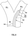
- FIG. 8 is a side view of a distal portion of an introducer or guide catheter 800 including tubular sheath 102.
- Guide catheter 800 may be utilized in any application in which it is desirable to orient or position a distal end of the apparatus in a direction different from that of the longitudinal axis of the apparatus, such as during navigation within a bifurcation or through tortuous anatomy. Exemplary applications include accessing the carotid, iliac or renal bifurcations, in either diagnostic or therapeutic applications.
- FIG. 8 is a side view of a distal portion of an introducer or guide catheter 800 including tubular sheath 102.
- Guide catheter 800 may be utilized in any application in which it is desirable to orient or position a distal end of the apparatus in a direction different from that of the longitudinal axis of the apparatus, such as during navigation within a bifurcation or through tortuous anatomy. Exemplary applications include accessing the carotid,
- guide catheter 800 is being delivered in situ and is positioned within the vasculature at a bifurcation having a main vessel MV, a first branch vessel BV 1 , and a second branch vessel BV 2 .
- central lumen 108 of tubular sheath 102 is sized or configured to slidingly receive a medical device 180 such as a guidewire or a treatment catheter there-through.
- tubular sheath 102 may be selectively bent or curved at two distinct radii, i.e ., first radius of curvature R 1 and second radius of curvature R 2 , in order to conform to the shape of the anatomy.
- first radius of curvature R 1 and second radius of curvature R 2 in order to conform to the shape of the anatomy.
- tubular sheath 102 is only selectively bent or curved at one distinct radii, i.e ., first radius of curvature R 1 , in order to confirm to the shape of the bifurcation such that distal end 106 of tubular sheath 102 is directed towards second branch vessel BV 2 .
- Medical device 180 is shown inserted through guide catheter 800 and extending into second branch vessel BV 2 .
- a proximal end (not shown) of guide catheter 800 may include a touhy borst adaptor or gasket (not shown) to prevent backflow of fluids and secure the position of medical device 180 when closed as will be understood by one of ordinary skill in the art.
- FIG. 9 is a cross-sectional view of a tubular sheath 902 according to another embodiment hereof.
- Tubular sheath 902 includes a plurality of steering mechanisms 920A, 920B at opposing sides thereof. More particularly, tubular sheath 902 defines a central lumen 908 extending there-through and two opposing longitudinally-extending lumens 912A, 912B are formed with a wall 910 of tubular sheath 902. Stated another way, longitudinally-extending lumens 912A, 912B are formed along opposing sides of tubular sheath 902.
- Steering mechanisms 920A, 920B are coaxially disposed within longitudinally-extending lumens 912A, 912B, respectively.
- Steering mechanism 920A includes a pull tube 922A and a pull wire 932A slidingly disposed within a lumen of pull tube 922A as described above with respect to pull tube 122 and pull wire 132
- steering mechanism 920B includes a pull tube 922B and a pull wire 932B slidingly disposed within a lumen of pull tube 922B as described above with respect to pull tube 122 and pull wire 132.
- tubular sheath 902 may be selectively curved or bent in opposite directions or orientations. Although shown with only two steering mechanisms, more than two steering mechanisms may be incorporated into tubular sheath 902 in order to permit bending of tubular sheath 902 in multiple directions or planes.
- FIG. 10 is a cross-sectional view of a tubular sheath 1002 according to another embodiment hereof
- FIG. 11 is a side view of the tubular sheath 1002.
- Tubular sheath 1002 includes a steering mechanism 1020 with three nesting or telescoping tubular components.
- tubular sheath 1002 defines a central lumen 1008 extending there-through and a longitudinally-extending lumen 1012 is formed with a wall 1010 of tubular sheath 1002.
- Steering mechanism 1020 is coaxially disposed within longitudinally-extending lumen 1012.
- Steering mechanism 1020 includes a pull tube 1022 and a pull wire 1032 slidingly disposed within a lumen of pull tube 1022 as described above with respect to pull tube 122 and pull wire 132.
- steering mechanism includes an additional or outer pull tube 1090 disposed over pull tube 1022. Stated another way, pull tube 1022 is slidingly disposed within a lumen of outer pull tube 1090.
- outer pull tube 1090 has a third anchor point 1092 (shown in FIG.
- third anchor point 1092 of outer pull tube 1090 is proximally spaced from the distal end of pull tube 1022.
- Tensioning or pulling of outer pull tube 1090 bends or curves another portion of tubular sheath 1002, i.e ., the region or portion of tubular sheath 1002 which is adjacent to the third anchor point of outer pull tube 1090, to a third radius of curvature R 3 (shown in FIG.
Landscapes
- Health & Medical Sciences (AREA)
- Engineering & Computer Science (AREA)
- Life Sciences & Earth Sciences (AREA)
- Biomedical Technology (AREA)
- Animal Behavior & Ethology (AREA)
- Veterinary Medicine (AREA)
- Public Health (AREA)
- General Health & Medical Sciences (AREA)
- Heart & Thoracic Surgery (AREA)
- Oral & Maxillofacial Surgery (AREA)
- Cardiology (AREA)
- Vascular Medicine (AREA)
- Transplantation (AREA)
- Biophysics (AREA)
- Hematology (AREA)
- Mechanical Engineering (AREA)
- Pulmonology (AREA)
- Anesthesiology (AREA)
- Media Introduction/Drainage Providing Device (AREA)
- Surgery (AREA)
- Nuclear Medicine, Radiotherapy & Molecular Imaging (AREA)
- Medical Informatics (AREA)
- Molecular Biology (AREA)
Claims (13)
- Lenkbarer Katheter (100), umfassend:eine rohrförmige Hülle (102) die ein Lumen (112) aufweist, das innerhalb einer Wand (110, 110B) davon ausgebildet ist; undeinen Lenkmechanismus (120), der innerhalb des Lumens (112) angeordnet ist, wobei der Lenkmechanismus (120) erste und zweite Lenkkomponenten (122, 132) umfasst, wobei mindestens ein Segment der zweiten Lenkkomponente (132) koaxial innerhalb der ersten Lenkkomponente (122) angeordnet ist, wobei die erste Lenkkomponente (122) und die zweite Lenkkomponente (132) separat gespannt sind, um entsprechende Bereiche der rohrförmigen Hülle (102) zu biegen.
- Katheter nach Anspruch 1, wobei ein distales Ende (126) der ersten Lenkkomponente (122) an einem ersten Ankerpunkt (128) an der rohrförmigen Hülle (102) befestigt ist und ein distales Ende (136) der zweiten Lenkkomponente (132) an einem zweiten Ankerpunkt (138) an der rohrförmigen Hülle (102) befestigt ist und wobei der zweite Ankerpunkt (138) distal von dem ersten Ankerpunkt (128) liegt.
- Katheter nach Anspruch 2, wobei der erste Ankerpunkt (128) proximal von einem distalen Ende (106) der rohrförmigen Hülle (102) beabstandet ist, sodass das Spannen der ersten Lenkkomponente (122) einen proximalen Bereich des Katheters auf einen ersten Krümmungsradius (R1) biegt.
- Katheter nach Anspruch 3, wobei sich der zweite Ankerpunkt (138) an dem distalen Ende (106) der rohrförmigen Hülle (102) befindet, sodass das Spannen der zweiten Lenkkomponente (132) einen distalen Bereich des Katheters auf einen zweiten Krümmungsradius (R2) biegt.
- Katheter nach Anspruch 4, wobei der erste und der zweite Krümmungsradius (R1, R2) voneinander unterschiedlich sind.
- Katheter nach Anspruch 2, wobei sich ein distales Segment (142) der zweiten Lenkkomponente (132) von dem distalen Ende (126) der ersten Lenkkomponente (122) zu dem zweiten Ankerpunkt (138) erstreckt und verschiebbar in einem entsprechenden distalen Abschnitt des Lumens (112) der rohrförmigen Hülle (102) angeordnet ist.
- Lenkbarer Führungskatheter (800), umfassend:eine rohrförmige Hülle (102), die ein zentrales Lumen (108, 108B) definiert, das bemessen ist, um eine medizinische Vorrichtung (180) dort hindurch aufzunehmen, wobei ein sich in Längsrichtung erstreckendes Lumen (112) mit einer Wand (110, HOB) der rohrförmigen Hülle (102) ausgebildet ist;ein Zugrohr (122), das ein Zugdrahtlumen (123) definiert, wobei das Zugrohr (122) ein distales Ende (126) aufweist, das an einem ersten Ankerpunkt (128) an der rohrförmigen Hülle (102) befestigt ist und mindestens ein Segment aufweist, das verschiebbar innerhalb des sich in Längsrichtung erstreckenden Lumens (112) der rohrförmigen Hülle (102) angeordnet ist; undeinen Zugdraht (132), der ein distales Ende (136) aufweist, das an einem zweiten Ankerpunkt (138) an der rohrförmigen Hülle (102) befestigt ist und mindestens ein Segment aufweist, das verschiebbar innerhalb des Zugdrahtlumens (123) des Zugrohrs (122) angeordnet ist, wobei der zweite Ankerpunkt (138) distal von dem ersten Ankerpunkt (128) liegt, undwobei das Zugrohr (122) und der Zugdraht (132) separat gespannt sind, um entsprechende Bereiche der rohrförmigen Hülle (102) zu biegen.
- Führungskatheter nach Anspruch 7, wobei der erste Ankerpunkt (128) proximal von einem distalen Ende (106) der rohrförmigen Hülle (102) beabstandet ist, sodass das Spannen des Zugrohrs (122) einen proximalen Bereich des Führungskatheters (800) auf einen ersten Krümmungsradius (R1) biegt.
- Führungskatheter nach Anspruch 8, wobei sich der zweite Ankerpunkt (138) an dem distalen Ende (106) der rohrförmigen Hülle (102) befindet, sodass das Spannen des Zugdrahts (132) einen distalen Bereich des Führungskatheters (800) auf einen zweiten Krümmungsradius (R2) biegt.
- Führungskatheter nach Anspruch 9, wobei der erste und der zweite Krümmungsradius (R1, R2) voneinander unterschiedlich sind.
- Führungskatheter nach Anspruch 9, wobei der proximale Bereich proximal des distalen Endes (126) des Zugrohrs (122) liegt und der distale Bereich distal des distalen Endes (126) des Zugrohrs (122) liegt.
- Führungskatheter nach Anspruch 7, wobei die Segmente des Zugrohrs (122) und der Zugdraht (132) koaxial innerhalb des sich in Längsrichtung erstreckenden Lumens (112) der rohrförmigen Hülle (102) angeordnet sind.
- Führungskatheter nach Anspruch 7, wobei sich ein distales Segment des Zugdrahts (132) von dem distalen Ende (126) des Zugrohrs (122) zu dem zweiten Ankerpunkt (138) erstreckt und verschiebbar in einem entsprechenden distalen Abschnitt des sich in Längsrichtung erstreckenden Lumens (112) der rohrförmigen Hülle (102) angeordnet ist.
Applications Claiming Priority (2)
| Application Number | Priority Date | Filing Date | Title |
|---|---|---|---|
| US15/065,938 US10278852B2 (en) | 2016-03-10 | 2016-03-10 | Steerable catheter with multiple bending radii via a steering mechanism with telescoping tubular components |
| PCT/US2017/020974 WO2017155892A1 (en) | 2016-03-10 | 2017-03-06 | Steerable catheter with multiple bending radii via a steering mechanism with telescoping tubular components |
Publications (2)
| Publication Number | Publication Date |
|---|---|
| EP3426331A1 EP3426331A1 (de) | 2019-01-16 |
| EP3426331B1 true EP3426331B1 (de) | 2023-07-05 |
Family
ID=58348022
Family Applications (1)
| Application Number | Title | Priority Date | Filing Date |
|---|---|---|---|
| EP17711533.4A Active EP3426331B1 (de) | 2016-03-10 | 2017-03-06 | Lenkbarer katheter mit mehreren krümmungsradien über einen lenkmechanismus mit teleskopischen rohrförmigen komponenten |
Country Status (5)
| Country | Link |
|---|---|
| US (1) | US10278852B2 (de) |
| EP (1) | EP3426331B1 (de) |
| CN (1) | CN108778387B (de) |
| AU (1) | AU2017229111B2 (de) |
| WO (1) | WO2017155892A1 (de) |
Families Citing this family (101)
| Publication number | Priority date | Publication date | Assignee | Title |
|---|---|---|---|---|
| US7704277B2 (en) | 2004-09-14 | 2010-04-27 | Edwards Lifesciences Ag | Device and method for treatment of heart valve regurgitation |
| CA3050938C (en) | 2004-10-02 | 2021-10-19 | Edwards Lifesciences Cardiaq Llc | Methods and devices for repair or replacement of heart valves or adjacent tissue without the need for full cardiopulmonary support |
| US8092520B2 (en) | 2005-11-10 | 2012-01-10 | CardiAQ Technologies, Inc. | Vascular prosthesis connecting stent |
| WO2008013915A2 (en) | 2006-07-28 | 2008-01-31 | Arshad Quadri | Percutaneous valve prosthesis and system and method for implanting same |
| US20090276040A1 (en) | 2008-05-01 | 2009-11-05 | Edwards Lifesciences Corporation | Device and method for replacing mitral valve |
| EP2367505B1 (de) | 2008-09-29 | 2020-08-12 | Edwards Lifesciences CardiAQ LLC | Herzklappe |
| EP2810620B1 (de) | 2009-04-15 | 2022-09-14 | Edwards Lifesciences CardiAQ LLC | Gefäßimplantat und Freisetzungssystem |
| EP2429455B8 (de) | 2009-04-29 | 2021-12-15 | Edwards Lifesciences Corporation | Vorrichtung für den ersatz einer defekten herzklappe |
| US8449599B2 (en) | 2009-12-04 | 2013-05-28 | Edwards Lifesciences Corporation | Prosthetic valve for replacing mitral valve |
| AU2011271007A1 (en) | 2010-06-21 | 2013-01-31 | Cardiaq Valve Technologies, Inc. | Replacement heart valve |
| EP2618784B1 (de) | 2010-09-23 | 2016-05-25 | Edwards Lifesciences CardiAQ LLC | Künstliche herzklappen und vorrichtungen |
| US12502276B2 (en) | 2011-05-16 | 2025-12-23 | Edwards Lifesciences Corporation | Inversion delivery device and method for a prosthesis |
| EP3593740B1 (de) | 2012-06-20 | 2021-10-06 | Stryker Corporation | System zur ausseraxialen gewebebehandlung |
| US9439763B2 (en) | 2013-02-04 | 2016-09-13 | Edwards Lifesciences Corporation | Prosthetic valve for replacing mitral valve |
| US20140277427A1 (en) | 2013-03-14 | 2014-09-18 | Cardiaq Valve Technologies, Inc. | Prosthesis for atraumatically grasping intralumenal tissue and methods of delivery |
| US9730791B2 (en) | 2013-03-14 | 2017-08-15 | Edwards Lifesciences Cardiaq Llc | Prosthesis for atraumatically grasping intralumenal tissue and methods of delivery |
| CN106170269B (zh) | 2014-02-21 | 2019-01-11 | 爱德华兹生命科学卡迪尔克有限责任公司 | 用于瓣膜替代品的受控部署的递送装置 |
| EP4470506A3 (de) | 2014-05-19 | 2025-01-08 | Edwards Lifesciences CardiAQ LLC | Ersatzmitralklappe mit ringförmiger krempe |
| US9532870B2 (en) | 2014-06-06 | 2017-01-03 | Edwards Lifesciences Corporation | Prosthetic valve for replacing a mitral valve |
| WO2016048802A1 (en) | 2014-09-28 | 2016-03-31 | Cardiokinetix, Inc. | Apparatuses for treating cardiac dysfunction |
| CN106999281B (zh) | 2014-11-26 | 2020-05-05 | 爱德华兹生命科学公司 | 经导管人工心脏瓣膜和递送系统 |
| US10751064B2 (en) | 2015-03-20 | 2020-08-25 | Edwards Lifescience Corporation | Systems and methods for delivering an implantable device |
| US10376363B2 (en) | 2015-04-30 | 2019-08-13 | Edwards Lifesciences Cardiaq Llc | Replacement mitral valve, delivery system for replacement mitral valve and methods of use |
| WO2016209970A1 (en) | 2015-06-22 | 2016-12-29 | Edwards Lifescience Cardiaq Llc | Actively controllable heart valve implant and methods of controlling same |
| US10092400B2 (en) | 2015-06-23 | 2018-10-09 | Edwards Lifesciences Cardiaq Llc | Systems and methods for anchoring and sealing a prosthetic heart valve |
| US10575951B2 (en) | 2015-08-26 | 2020-03-03 | Edwards Lifesciences Cardiaq Llc | Delivery device and methods of use for transapical delivery of replacement mitral valve |
| US10117744B2 (en) | 2015-08-26 | 2018-11-06 | Edwards Lifesciences Cardiaq Llc | Replacement heart valves and methods of delivery |
| US10350066B2 (en) | 2015-08-28 | 2019-07-16 | Edwards Lifesciences Cardiaq Llc | Steerable delivery system for replacement mitral valve and methods of use |
| US10350062B2 (en) | 2016-07-21 | 2019-07-16 | Edwards Lifesciences Corporation | Replacement heart valve prosthesis |
| AU2017343922A1 (en) | 2016-10-14 | 2019-05-02 | Fisher & Paykel Healthcare Limited | Breath sampling interface |
| KR20200010161A (ko) | 2016-11-22 | 2020-01-30 | 시네코어 엘엘씨 | 승모판의 치료 장치를 위한 비가이드와이어 중격경유 전달 시스템 |
| ES2923913T3 (es) | 2017-07-06 | 2022-10-03 | Edwards Lifesciences Corp | Sistema de suministro de carril orientable |
| WO2019055154A2 (en) | 2017-08-06 | 2019-03-21 | Synecor Llc | SYSTEMS AND METHODS FOR THE TRANSSEPTIVE DELIVERY OF HEART THERAPEUTIC DEVICES |
| US11925555B2 (en) * | 2017-08-24 | 2024-03-12 | Tricares SAS | Double steerable sheath and method for deployment of a medical device |
| CN111818877B (zh) | 2018-01-25 | 2023-12-22 | 爱德华兹生命科学公司 | 在部署后用于辅助置换瓣膜重新捕获和重新定位的递送系统 |
| US11051934B2 (en) | 2018-02-28 | 2021-07-06 | Edwards Lifesciences Corporation | Prosthetic mitral valve with improved anchors and seal |
| WO2019180268A1 (en) * | 2018-03-23 | 2019-09-26 | Aran Biomedical Teoranta | A steerable catheter |
| WO2019195860A2 (en) | 2018-04-04 | 2019-10-10 | Vdyne, Llc | Devices and methods for anchoring transcatheter heart valve |
| US12156979B2 (en) * | 2018-05-21 | 2024-12-03 | St. Jude Medical, Cardiology Division, Inc. | Deflectable catheter shaft with pullwire anchor feature |
| NL2021140B1 (en) * | 2018-06-18 | 2020-01-06 | Crea Ip B V | Steerable Ophthalmic Probe comprising Actuation Assembly |
| US10595994B1 (en) | 2018-09-20 | 2020-03-24 | Vdyne, Llc | Side-delivered transcatheter heart valve replacement |
| US11344413B2 (en) | 2018-09-20 | 2022-05-31 | Vdyne, Inc. | Transcatheter deliverable prosthetic heart valves and methods of delivery |
| US10321995B1 (en) | 2018-09-20 | 2019-06-18 | Vdyne, Llc | Orthogonally delivered transcatheter heart valve replacement |
| US12186187B2 (en) | 2018-09-20 | 2025-01-07 | Vdyne, Inc. | Transcatheter deliverable prosthetic heart valves and methods of delivery |
| US11071627B2 (en) | 2018-10-18 | 2021-07-27 | Vdyne, Inc. | Orthogonally delivered transcatheter heart valve frame for valve in valve prosthesis |
| US11278437B2 (en) | 2018-12-08 | 2022-03-22 | Vdyne, Inc. | Compression capable annular frames for side delivery of transcatheter heart valve replacement |
| US11109969B2 (en) | 2018-10-22 | 2021-09-07 | Vdyne, Inc. | Guidewire delivery of transcatheter heart valve |
| US20210386972A1 (en) * | 2018-10-25 | 2021-12-16 | Canon U.S.A., Inc. | Medical apparatus with reflow trapped anchors and method of use thereof |
| JP7229351B2 (ja) | 2018-10-31 | 2023-02-27 | キヤノン ユーエスエイ,インコーポレイテッド | 分布した空洞を有する医用装置及びその使用方法 |
| CN111110985B (zh) * | 2018-10-31 | 2025-04-15 | 杭州唯强医疗科技有限公司 | 调弯手柄及可调弯导管 |
| JP2022510111A (ja) * | 2018-12-02 | 2022-01-26 | エンプレス メディカル,インク. | 組織塊を周る張力部材の通線 |
| US11253359B2 (en) | 2018-12-20 | 2022-02-22 | Vdyne, Inc. | Proximal tab for side-delivered transcatheter heart valves and methods of delivery |
| EP3903872B1 (de) * | 2018-12-29 | 2024-06-05 | Hangzhou Endonom Medtech Co., Ltd | Biegbarer katheter |
| WO2020146842A1 (en) | 2019-01-10 | 2020-07-16 | Vdyne, Llc | Anchor hook for side-delivery transcatheter heart valve prosthesis |
| US11185409B2 (en) | 2019-01-26 | 2021-11-30 | Vdyne, Inc. | Collapsible inner flow control component for side-delivered transcatheter heart valve prosthesis |
| US11273032B2 (en) | 2019-01-26 | 2022-03-15 | Vdyne, Inc. | Collapsible inner flow control component for side-deliverable transcatheter heart valve prosthesis |
| WO2020163031A1 (en) | 2019-02-04 | 2020-08-13 | Edwards Lifesciences Corporation | Guide wire apparatuses and methods |
| US11065438B2 (en) | 2019-02-07 | 2021-07-20 | Synecor Llc | Systems and methods for transseptal delivery of percutaneous ventricular assist devices and other non-guidewire based transvascular therapeutic devices |
| EP3934583B1 (de) | 2019-03-05 | 2023-12-13 | Vdyne, Inc. | Vorrichtungen zur kontrolle der trikuspidalregurgitation für orthogonale transkatheter-herzklappenprothesen |
| US11076956B2 (en) | 2019-03-14 | 2021-08-03 | Vdyne, Inc. | Proximal, distal, and anterior anchoring tabs for side-delivered transcatheter mitral valve prosthesis |
| US11173027B2 (en) | 2019-03-14 | 2021-11-16 | Vdyne, Inc. | Side-deliverable transcatheter prosthetic valves and methods for delivering and anchoring the same |
| EP3952790A1 (de) | 2019-04-12 | 2022-02-16 | W.L. Gore & Associates, Inc. | Ventil mit mehrteiligem rahmen und zugehörigen elastischen überbrückungsmerkmalen |
| WO2020219459A1 (en) | 2019-04-23 | 2020-10-29 | Edwards Lifesciences Corporation | Motorized implant delivery system |
| CN110559022B (zh) * | 2019-04-30 | 2023-11-24 | 上海科赐医疗技术有限公司 | 具有操控器的医用非对称球囊导管 |
| JP7529689B2 (ja) | 2019-05-04 | 2024-08-06 | ブイダイン,インコーポレイテッド | 生来の弁輪での側方送達される人工心臓弁を展開するための締め付けデバイス及び方法 |
| US11253265B2 (en) * | 2019-06-18 | 2022-02-22 | DePuy Synthes Products, Inc. | Pull wire detachment for intravascular devices |
| US11446145B2 (en) | 2019-07-25 | 2022-09-20 | Medtronic, Inc. | Delivery device having a capsule for delivering a prosthesis and a pull wire for steering the capsule |
| CN114786757B (zh) | 2019-08-02 | 2025-02-21 | 维扎拉梅德公司 | 可转向护套 |
| WO2021035032A1 (en) | 2019-08-20 | 2021-02-25 | Vdyne, Inc. | Delivery and retrieval devices and methods for side-deliverable transcatheter prosthetic valves |
| CN120531525A (zh) | 2019-08-26 | 2025-08-26 | 维迪内股份有限公司 | 可侧面输送的经导管假体瓣膜及其输送和锚定方法 |
| CA3143177A1 (en) | 2019-08-28 | 2021-03-04 | Valtech Cardio, Ltd. | Low-profile steerable catheter |
| EP4031222A4 (de) * | 2019-09-16 | 2023-11-15 | Middleton Medical Innovations Pty Ltd | Harnkatheter und verfahren zum katheterisieren einer blase unter verwendung eines aktiv ablenkbaren harnröhrenkatheters und eines ablenkmechanismus |
| CN112972166A (zh) * | 2019-12-17 | 2021-06-18 | 先健科技(深圳)有限公司 | 医疗器械系统 |
| US11234813B2 (en) | 2020-01-17 | 2022-02-01 | Vdyne, Inc. | Ventricular stability elements for side-deliverable prosthetic heart valves and methods of delivery |
| US11992241B2 (en) * | 2020-01-31 | 2024-05-28 | DePuy Synthes Products, Inc. | System to assist delivery of a mechanical intravascular treatment device |
| CA3108966A1 (en) * | 2020-02-17 | 2021-08-17 | Melissa Jones | Steerable endovascular catheter |
| JP7510508B2 (ja) * | 2020-02-24 | 2024-07-03 | キヤノン ユーエスエイ,インコーポレイテッド | カテーテル標的ロックのための方法及びシステム |
| US20230210660A1 (en) | 2020-06-04 | 2023-07-06 | Medtronic, Inc. | Delivery system having a split distal tip for improved positioning of a transcatheter heart valve |
| US12544540B2 (en) * | 2020-06-25 | 2026-02-10 | Greatbatch Ltd. | Braid and pull wire containment ring for deflectable guiding catheter |
| CN111840753A (zh) * | 2020-08-18 | 2020-10-30 | 上海上医康鸽医用器材有限责任公司 | 内腔可调节导管装置 |
| CN112057135B (zh) * | 2020-08-31 | 2022-11-01 | 武汉佑康科技有限公司 | 一种具有无级自锁手柄的电子镜导管结构 |
| WO2022132569A1 (en) | 2020-12-18 | 2022-06-23 | Edwards Lifesciences Corporation | Storage jar assembly for aprosthetic heart valve |
| JP7619124B2 (ja) | 2021-03-30 | 2025-01-22 | 住友ベークライト株式会社 | 医療用留置具搬送装置及び留置具付き医療用留置具搬送装置 |
| US12521527B2 (en) | 2021-05-28 | 2026-01-13 | Medtronic Vascular, Inc. | Steerable catheter device |
| WO2023285967A1 (en) | 2021-07-16 | 2023-01-19 | Medtronic, Inc. | Transcatheter valve delivery system with omnidirectional steering and methods of use thereof |
| US20230016149A1 (en) * | 2021-07-16 | 2023-01-19 | Medtronic, Inc. | Transcatheter valve delivery system with omnidirectional steering and methods of use thereof |
| KR102918984B1 (ko) | 2021-10-27 | 2026-01-28 | 에드워즈 라이프사이언시스 코포레이션 | 인공 심장 판막의 클림핑 및 로딩을 위한 시스템 및 방법 |
| CN114177477B (zh) * | 2021-11-26 | 2024-02-13 | 上海以心医疗器械有限公司 | 一种调弯装置、调弯鞘管及医疗系统 |
| US20230172611A1 (en) * | 2021-12-06 | 2023-06-08 | Coherex Medical, Inc. | Deflectable sheath for left atrial appendage device, system, and method thereof |
| WO2023144670A1 (en) | 2022-01-28 | 2023-08-03 | Medtronic, Inc. | Hydraulic deployment and recapture system for a prosthetic heart valve |
| US20250049569A1 (en) | 2022-01-28 | 2025-02-13 | Medtronic, Inc. | Transcatheter valve delivery system with improved loading and deployment |
| EP4468999A1 (de) | 2022-01-28 | 2024-12-04 | Medtronic, Inc. | Systeme für transkatheterklappenersatz und verfahren |
| CN114796819A (zh) * | 2022-05-26 | 2022-07-29 | 康迪泰科(北京)医疗科技有限公司 | 一种扩张器 |
| CN118161320A (zh) * | 2022-12-02 | 2024-06-11 | 先健科技(深圳)有限公司 | 一种输送系统 |
| CN120569163A (zh) | 2022-12-06 | 2025-08-29 | 波士顿科学国际有限公司 | 微创手术期间用于切割缝合线的医疗装置 |
| EP4673198A1 (de) * | 2023-03-01 | 2026-01-07 | Medtronic, Inc. | Vorrichtung für einen katheter mit steuerbarer freisetzung |
| WO2024246750A1 (en) | 2023-06-02 | 2024-12-05 | Medtronic, Inc. | Transcatheter valve delivery system with a telescopic capsule assembly and methods of use thereof |
| WO2025088513A1 (en) | 2023-10-27 | 2025-05-01 | Medtronic, Inc. | Transcatheter valve delivery system with a split capsule assembly and methods of use thereof |
| WO2025159957A1 (en) | 2024-01-26 | 2025-07-31 | Medtronic, Inc. | Delivery device having a capsule with an integral flexible region for delivering a prosthesis |
| CN118592872A (zh) * | 2024-06-28 | 2024-09-06 | 广州瑞派医疗器械有限责任公司 | 内窥镜的操纵组件及内窥镜 |
| CN119633234A (zh) * | 2024-12-13 | 2025-03-18 | 中国医学科学院阜外医院 | 一种用于主动脉瓣跨瓣的引导系统 |
Family Cites Families (23)
| Publication number | Priority date | Publication date | Assignee | Title |
|---|---|---|---|---|
| GR920100104A (el) | 1992-03-13 | 1993-11-30 | Christodoulos I Stefanadis | Προσωρινή διαυλική ενδοπρόσ?εση υποστήριξης αγγειακού τοιχώματος. |
| US5318525A (en) | 1992-04-10 | 1994-06-07 | Medtronic Cardiorhythm | Steerable electrode catheter |
| US6132390A (en) | 1996-02-28 | 2000-10-17 | Eupalamus Llc | Handle for manipulation of a stylet used for deflecting a tip of a lead or catheter |
| US5876373A (en) | 1997-04-04 | 1999-03-02 | Eclipse Surgical Technologies, Inc. | Steerable catheter |
| US6730058B2 (en) | 2001-09-13 | 2004-05-04 | Cardiac Pacemakers, Inc. | Adjustable profile steerable catheter |
| AU2002226252A1 (en) * | 2002-02-07 | 2003-09-02 | Carag Ag | Displacement device for a catheter |
| JP4447011B2 (ja) | 2003-07-21 | 2010-04-07 | ザ・トラスティーズ・オブ・ザ・ユニバーシティ・オブ・ペンシルバニア | 経皮的心臓弁 |
| US7717875B2 (en) | 2004-07-20 | 2010-05-18 | St. Jude Medical, Atrial Fibrillation Division, Inc. | Steerable catheter with hydraulic or pneumatic actuator |
| DE102005003632A1 (de) | 2005-01-20 | 2006-08-17 | Fraunhofer-Gesellschaft zur Förderung der angewandten Forschung e.V. | Katheter für die transvaskuläre Implantation von Herzklappenprothesen |
| US7780723B2 (en) | 2005-06-13 | 2010-08-24 | Edwards Lifesciences Corporation | Heart valve delivery system |
| CN101553190B (zh) | 2006-09-08 | 2011-06-15 | 爱德华兹生命科学公司 | 一体的心脏瓣膜运送系统 |
| US9114229B2 (en) * | 2006-12-29 | 2015-08-25 | St. Jude Medical, Af Division, Inc. | Dual braid reinforcement deflectable device |
| WO2009137712A1 (en) * | 2008-05-07 | 2009-11-12 | Guided Delivery Systems Inc. | Deflectable guide |
| US9254123B2 (en) * | 2009-04-29 | 2016-02-09 | Hansen Medical, Inc. | Flexible and steerable elongate instruments with shape control and support elements |
| US9320597B2 (en) | 2010-03-30 | 2016-04-26 | Medtronic, Inc. | Transcatheter prosthetic heart valve delivery system with recapturing feature and method |
| US8998980B2 (en) | 2010-04-09 | 2015-04-07 | Medtronic, Inc. | Transcatheter prosthetic heart valve delivery system with recapturing feature and method |
| US8926692B2 (en) | 2010-04-09 | 2015-01-06 | Medtronic, Inc. | Transcatheter prosthetic heart valve delivery device with partial deployment and release features and methods |
| US8512401B2 (en) | 2010-04-12 | 2013-08-20 | Medtronic, Inc. | Transcatheter prosthetic heart valve delivery system with funnel recapturing feature and method |
| CN102917668B (zh) | 2010-04-27 | 2015-01-28 | 美敦力公司 | 具有偏置释放结构的经导管假体心脏瓣膜输送装置 |
| AU2011288975B2 (en) | 2010-08-13 | 2015-07-30 | Cathrx Ltd | A catheter assembly with deflection size adjustability |
| US8926588B2 (en) | 2011-07-05 | 2015-01-06 | Medtronic Vascular, Inc. | Steerable delivery catheter |
| ITPD20130020A1 (it) * | 2013-01-30 | 2014-07-31 | Gioachino Coppi | Catetere a curvatura variabile |
| CN204502031U (zh) * | 2015-01-20 | 2015-07-29 | 周玉杰 | 一种带可塑形内芯的指引导管 |
-
2016
- 2016-03-10 US US15/065,938 patent/US10278852B2/en active Active
-
2017
- 2017-03-06 CN CN201780015859.1A patent/CN108778387B/zh active Active
- 2017-03-06 AU AU2017229111A patent/AU2017229111B2/en not_active Ceased
- 2017-03-06 EP EP17711533.4A patent/EP3426331B1/de active Active
- 2017-03-06 WO PCT/US2017/020974 patent/WO2017155892A1/en not_active Ceased
Also Published As
| Publication number | Publication date |
|---|---|
| CN108778387B (zh) | 2021-10-15 |
| AU2017229111A1 (en) | 2018-09-06 |
| WO2017155892A1 (en) | 2017-09-14 |
| EP3426331A1 (de) | 2019-01-16 |
| US10278852B2 (en) | 2019-05-07 |
| CN108778387A (zh) | 2018-11-09 |
| AU2017229111B2 (en) | 2020-03-12 |
| US20170258614A1 (en) | 2017-09-14 |
Similar Documents
| Publication | Publication Date | Title |
|---|---|---|
| EP3426331B1 (de) | Lenkbarer katheter mit mehreren krümmungsradien über einen lenkmechanismus mit teleskopischen rohrförmigen komponenten | |
| US12329916B2 (en) | Catheter handle with torque mechanism and valve relief component | |
| EP3490658B1 (de) | Mit einer aussenhülle ausgestattete intravaskuläre zufuhrvorrichtung | |
| US11338111B2 (en) | Vascular re-entry catheter | |
| EP4272795B1 (de) | Einstellbarer gebogener katheter | |
| EP3490659B1 (de) | Mechanische verriegelung für katheter | |
| EP1804882B1 (de) | Katheter mit vorgeformter distaler spitze | |
| US9750397B2 (en) | Mechanism of small drive wire retention on spool | |
| EP3332830B1 (de) | Führungsverlängerungskatheter | |
| US9427550B2 (en) | Devices and methods for delivering vascular implants | |
| JP2009524490A (ja) | 変向調整カテーテル及びサポートカテーテル並びにその使用法 | |
| EP4410350A1 (de) | Kathetergriff mit drehmomentmechanismus und ventilentlastungskomponente | |
| US20230123266A1 (en) | Catheter handle with torque mechanism and valve relief component |
Legal Events
| Date | Code | Title | Description |
|---|---|---|---|
| STAA | Information on the status of an ep patent application or granted ep patent |
Free format text: STATUS: UNKNOWN |
|
| STAA | Information on the status of an ep patent application or granted ep patent |
Free format text: STATUS: THE INTERNATIONAL PUBLICATION HAS BEEN MADE |
|
| PUAI | Public reference made under article 153(3) epc to a published international application that has entered the european phase |
Free format text: ORIGINAL CODE: 0009012 |
|
| STAA | Information on the status of an ep patent application or granted ep patent |
Free format text: STATUS: REQUEST FOR EXAMINATION WAS MADE |
|
| 17P | Request for examination filed |
Effective date: 20180927 |
|
| AK | Designated contracting states |
Kind code of ref document: A1 Designated state(s): AL AT BE BG CH CY CZ DE DK EE ES FI FR GB GR HR HU IE IS IT LI LT LU LV MC MK MT NL NO PL PT RO RS SE SI SK SM TR |
|
| AX | Request for extension of the european patent |
Extension state: BA ME |
|
| DAV | Request for validation of the european patent (deleted) | ||
| DAX | Request for extension of the european patent (deleted) | ||
| RIC1 | Information provided on ipc code assigned before grant |
Ipc: A61F 2/966 20130101ALI20221202BHEP Ipc: A61M 25/01 20060101AFI20221202BHEP |
|
| GRAP | Despatch of communication of intention to grant a patent |
Free format text: ORIGINAL CODE: EPIDOSNIGR1 |
|
| STAA | Information on the status of an ep patent application or granted ep patent |
Free format text: STATUS: GRANT OF PATENT IS INTENDED |
|
| INTG | Intention to grant announced |
Effective date: 20230207 |
|
| GRAS | Grant fee paid |
Free format text: ORIGINAL CODE: EPIDOSNIGR3 |
|
| GRAA | (expected) grant |
Free format text: ORIGINAL CODE: 0009210 |
|
| STAA | Information on the status of an ep patent application or granted ep patent |
Free format text: STATUS: THE PATENT HAS BEEN GRANTED |
|
| AK | Designated contracting states |
Kind code of ref document: B1 Designated state(s): AL AT BE BG CH CY CZ DE DK EE ES FI FR GB GR HR HU IE IS IT LI LT LU LV MC MK MT NL NO PL PT RO RS SE SI SK SM TR |
|
| REG | Reference to a national code |
Ref country code: CH Ref legal event code: EP |
|
| REG | Reference to a national code |
Ref country code: AT Ref legal event code: REF Ref document number: 1584256 Country of ref document: AT Kind code of ref document: T Effective date: 20230715 |
|
| REG | Reference to a national code |
Ref country code: DE Ref legal event code: R096 Ref document number: 602017070906 Country of ref document: DE |
|
| REG | Reference to a national code |
Ref country code: IE Ref legal event code: FG4D |
|
| REG | Reference to a national code |
Ref country code: LT Ref legal event code: MG9D |
|
| REG | Reference to a national code |
Ref country code: NL Ref legal event code: MP Effective date: 20230705 |
|
| REG | Reference to a national code |
Ref country code: AT Ref legal event code: MK05 Ref document number: 1584256 Country of ref document: AT Kind code of ref document: T Effective date: 20230705 |
|
| PG25 | Lapsed in a contracting state [announced via postgrant information from national office to epo] |
Ref country code: NL Free format text: LAPSE BECAUSE OF FAILURE TO SUBMIT A TRANSLATION OF THE DESCRIPTION OR TO PAY THE FEE WITHIN THE PRESCRIBED TIME-LIMIT Effective date: 20230705 |
|
| PG25 | Lapsed in a contracting state [announced via postgrant information from national office to epo] |
Ref country code: GR Free format text: LAPSE BECAUSE OF FAILURE TO SUBMIT A TRANSLATION OF THE DESCRIPTION OR TO PAY THE FEE WITHIN THE PRESCRIBED TIME-LIMIT Effective date: 20231006 |
|
| PG25 | Lapsed in a contracting state [announced via postgrant information from national office to epo] |
Ref country code: ES Free format text: LAPSE BECAUSE OF FAILURE TO SUBMIT A TRANSLATION OF THE DESCRIPTION OR TO PAY THE FEE WITHIN THE PRESCRIBED TIME-LIMIT Effective date: 20230705 |
|
| PG25 | Lapsed in a contracting state [announced via postgrant information from national office to epo] |
Ref country code: IS Free format text: LAPSE BECAUSE OF FAILURE TO SUBMIT A TRANSLATION OF THE DESCRIPTION OR TO PAY THE FEE WITHIN THE PRESCRIBED TIME-LIMIT Effective date: 20231105 |
|
| PG25 | Lapsed in a contracting state [announced via postgrant information from national office to epo] |
Ref country code: SE Free format text: LAPSE BECAUSE OF FAILURE TO SUBMIT A TRANSLATION OF THE DESCRIPTION OR TO PAY THE FEE WITHIN THE PRESCRIBED TIME-LIMIT Effective date: 20230705 Ref country code: RS Free format text: LAPSE BECAUSE OF FAILURE TO SUBMIT A TRANSLATION OF THE DESCRIPTION OR TO PAY THE FEE WITHIN THE PRESCRIBED TIME-LIMIT Effective date: 20230705 Ref country code: PT Free format text: LAPSE BECAUSE OF FAILURE TO SUBMIT A TRANSLATION OF THE DESCRIPTION OR TO PAY THE FEE WITHIN THE PRESCRIBED TIME-LIMIT Effective date: 20231106 Ref country code: NO Free format text: LAPSE BECAUSE OF FAILURE TO SUBMIT A TRANSLATION OF THE DESCRIPTION OR TO PAY THE FEE WITHIN THE PRESCRIBED TIME-LIMIT Effective date: 20231005 Ref country code: LV Free format text: LAPSE BECAUSE OF FAILURE TO SUBMIT A TRANSLATION OF THE DESCRIPTION OR TO PAY THE FEE WITHIN THE PRESCRIBED TIME-LIMIT Effective date: 20230705 Ref country code: LT Free format text: LAPSE BECAUSE OF FAILURE TO SUBMIT A TRANSLATION OF THE DESCRIPTION OR TO PAY THE FEE WITHIN THE PRESCRIBED TIME-LIMIT Effective date: 20230705 Ref country code: IS Free format text: LAPSE BECAUSE OF FAILURE TO SUBMIT A TRANSLATION OF THE DESCRIPTION OR TO PAY THE FEE WITHIN THE PRESCRIBED TIME-LIMIT Effective date: 20231105 Ref country code: HR Free format text: LAPSE BECAUSE OF FAILURE TO SUBMIT A TRANSLATION OF THE DESCRIPTION OR TO PAY THE FEE WITHIN THE PRESCRIBED TIME-LIMIT Effective date: 20230705 Ref country code: GR Free format text: LAPSE BECAUSE OF FAILURE TO SUBMIT A TRANSLATION OF THE DESCRIPTION OR TO PAY THE FEE WITHIN THE PRESCRIBED TIME-LIMIT Effective date: 20231006 Ref country code: FI Free format text: LAPSE BECAUSE OF FAILURE TO SUBMIT A TRANSLATION OF THE DESCRIPTION OR TO PAY THE FEE WITHIN THE PRESCRIBED TIME-LIMIT Effective date: 20230705 Ref country code: ES Free format text: LAPSE BECAUSE OF FAILURE TO SUBMIT A TRANSLATION OF THE DESCRIPTION OR TO PAY THE FEE WITHIN THE PRESCRIBED TIME-LIMIT Effective date: 20230705 Ref country code: AT Free format text: LAPSE BECAUSE OF FAILURE TO SUBMIT A TRANSLATION OF THE DESCRIPTION OR TO PAY THE FEE WITHIN THE PRESCRIBED TIME-LIMIT Effective date: 20230705 |
|
| PG25 | Lapsed in a contracting state [announced via postgrant information from national office to epo] |
Ref country code: PL Free format text: LAPSE BECAUSE OF FAILURE TO SUBMIT A TRANSLATION OF THE DESCRIPTION OR TO PAY THE FEE WITHIN THE PRESCRIBED TIME-LIMIT Effective date: 20230705 |
|
| REG | Reference to a national code |
Ref country code: DE Ref legal event code: R097 Ref document number: 602017070906 Country of ref document: DE |
|
| PG25 | Lapsed in a contracting state [announced via postgrant information from national office to epo] |
Ref country code: SM Free format text: LAPSE BECAUSE OF FAILURE TO SUBMIT A TRANSLATION OF THE DESCRIPTION OR TO PAY THE FEE WITHIN THE PRESCRIBED TIME-LIMIT Effective date: 20230705 Ref country code: RO Free format text: LAPSE BECAUSE OF FAILURE TO SUBMIT A TRANSLATION OF THE DESCRIPTION OR TO PAY THE FEE WITHIN THE PRESCRIBED TIME-LIMIT Effective date: 20230705 Ref country code: EE Free format text: LAPSE BECAUSE OF FAILURE TO SUBMIT A TRANSLATION OF THE DESCRIPTION OR TO PAY THE FEE WITHIN THE PRESCRIBED TIME-LIMIT Effective date: 20230705 Ref country code: DK Free format text: LAPSE BECAUSE OF FAILURE TO SUBMIT A TRANSLATION OF THE DESCRIPTION OR TO PAY THE FEE WITHIN THE PRESCRIBED TIME-LIMIT Effective date: 20230705 Ref country code: CZ Free format text: LAPSE BECAUSE OF FAILURE TO SUBMIT A TRANSLATION OF THE DESCRIPTION OR TO PAY THE FEE WITHIN THE PRESCRIBED TIME-LIMIT Effective date: 20230705 Ref country code: SK Free format text: LAPSE BECAUSE OF FAILURE TO SUBMIT A TRANSLATION OF THE DESCRIPTION OR TO PAY THE FEE WITHIN THE PRESCRIBED TIME-LIMIT Effective date: 20230705 |
|
| PLBE | No opposition filed within time limit |
Free format text: ORIGINAL CODE: 0009261 |
|
| STAA | Information on the status of an ep patent application or granted ep patent |
Free format text: STATUS: NO OPPOSITION FILED WITHIN TIME LIMIT |
|
| PG25 | Lapsed in a contracting state [announced via postgrant information from national office to epo] |
Ref country code: IT Free format text: LAPSE BECAUSE OF FAILURE TO SUBMIT A TRANSLATION OF THE DESCRIPTION OR TO PAY THE FEE WITHIN THE PRESCRIBED TIME-LIMIT Effective date: 20230705 |
|
| 26N | No opposition filed |
Effective date: 20240408 |
|
| PG25 | Lapsed in a contracting state [announced via postgrant information from national office to epo] |
Ref country code: SI Free format text: LAPSE BECAUSE OF FAILURE TO SUBMIT A TRANSLATION OF THE DESCRIPTION OR TO PAY THE FEE WITHIN THE PRESCRIBED TIME-LIMIT Effective date: 20230705 |
|
| REG | Reference to a national code |
Ref country code: CH Ref legal event code: PL |
|
| PG25 | Lapsed in a contracting state [announced via postgrant information from national office to epo] |
Ref country code: BG Free format text: LAPSE BECAUSE OF FAILURE TO SUBMIT A TRANSLATION OF THE DESCRIPTION OR TO PAY THE FEE WITHIN THE PRESCRIBED TIME-LIMIT Effective date: 20230705 |
|
| PG25 | Lapsed in a contracting state [announced via postgrant information from national office to epo] |
Ref country code: LU Free format text: LAPSE BECAUSE OF NON-PAYMENT OF DUE FEES Effective date: 20240306 |
|
| PG25 | Lapsed in a contracting state [announced via postgrant information from national office to epo] |
Ref country code: MC Free format text: LAPSE BECAUSE OF FAILURE TO SUBMIT A TRANSLATION OF THE DESCRIPTION OR TO PAY THE FEE WITHIN THE PRESCRIBED TIME-LIMIT Effective date: 20230705 |
|
| GBPC | Gb: european patent ceased through non-payment of renewal fee |
Effective date: 20240306 |
|
| PG25 | Lapsed in a contracting state [announced via postgrant information from national office to epo] |
Ref country code: MC Free format text: LAPSE BECAUSE OF FAILURE TO SUBMIT A TRANSLATION OF THE DESCRIPTION OR TO PAY THE FEE WITHIN THE PRESCRIBED TIME-LIMIT Effective date: 20230705 Ref country code: LU Free format text: LAPSE BECAUSE OF NON-PAYMENT OF DUE FEES Effective date: 20240306 Ref country code: BG Free format text: LAPSE BECAUSE OF FAILURE TO SUBMIT A TRANSLATION OF THE DESCRIPTION OR TO PAY THE FEE WITHIN THE PRESCRIBED TIME-LIMIT Effective date: 20230705 |
|
| REG | Reference to a national code |
Ref country code: BE Ref legal event code: MM Effective date: 20240331 |
|
| PG25 | Lapsed in a contracting state [announced via postgrant information from national office to epo] |
Ref country code: BE Free format text: LAPSE BECAUSE OF NON-PAYMENT OF DUE FEES Effective date: 20240331 |
|
| PG25 | Lapsed in a contracting state [announced via postgrant information from national office to epo] |
Ref country code: GB Free format text: LAPSE BECAUSE OF NON-PAYMENT OF DUE FEES Effective date: 20240306 |
|
| PG25 | Lapsed in a contracting state [announced via postgrant information from national office to epo] |
Ref country code: GB Free format text: LAPSE BECAUSE OF NON-PAYMENT OF DUE FEES Effective date: 20240306 Ref country code: BE Free format text: LAPSE BECAUSE OF NON-PAYMENT OF DUE FEES Effective date: 20240331 Ref country code: CH Free format text: LAPSE BECAUSE OF NON-PAYMENT OF DUE FEES Effective date: 20240331 |
|
| PGFP | Annual fee paid to national office [announced via postgrant information from national office to epo] |
Ref country code: DE Payment date: 20250218 Year of fee payment: 9 |
|
| PGFP | Annual fee paid to national office [announced via postgrant information from national office to epo] |
Ref country code: IE Payment date: 20250220 Year of fee payment: 9 |
|
| PGFP | Annual fee paid to national office [announced via postgrant information from national office to epo] |
Ref country code: FR Payment date: 20250218 Year of fee payment: 9 |
|
| PG25 | Lapsed in a contracting state [announced via postgrant information from national office to epo] |
Ref country code: CY Free format text: LAPSE BECAUSE OF FAILURE TO SUBMIT A TRANSLATION OF THE DESCRIPTION OR TO PAY THE FEE WITHIN THE PRESCRIBED TIME-LIMIT; INVALID AB INITIO Effective date: 20170306 |
|
| PG25 | Lapsed in a contracting state [announced via postgrant information from national office to epo] |
Ref country code: HU Free format text: LAPSE BECAUSE OF FAILURE TO SUBMIT A TRANSLATION OF THE DESCRIPTION OR TO PAY THE FEE WITHIN THE PRESCRIBED TIME-LIMIT; INVALID AB INITIO Effective date: 20170306 |
|
| PG25 | Lapsed in a contracting state [announced via postgrant information from national office to epo] |
Ref country code: TR Free format text: LAPSE BECAUSE OF FAILURE TO SUBMIT A TRANSLATION OF THE DESCRIPTION OR TO PAY THE FEE WITHIN THE PRESCRIBED TIME-LIMIT Effective date: 20230705 |