EP3425450B1 - Wireless powered electrochromic windows - Google Patents
Wireless powered electrochromic windows Download PDFInfo
- Publication number
- EP3425450B1 EP3425450B1 EP18189681.2A EP18189681A EP3425450B1 EP 3425450 B1 EP3425450 B1 EP 3425450B1 EP 18189681 A EP18189681 A EP 18189681A EP 3425450 B1 EP3425450 B1 EP 3425450B1
- Authority
- EP
- European Patent Office
- Prior art keywords
- wireless power
- power
- window
- receiver
- electrochromic device
- Prior art date
- Legal status (The legal status is an assumption and is not a legal conclusion. Google has not performed a legal analysis and makes no representation as to the accuracy of the status listed.)
- Active
Links
Images



Classifications
-
- H—ELECTRICITY
- H02—GENERATION; CONVERSION OR DISTRIBUTION OF ELECTRIC POWER
- H02J—ELECTRIC POWER NETWORKS; CIRCUIT ARRANGEMENTS OR SYSTEMS FOR SUPPLYING OR DISTRIBUTING ELECTRIC POWER; SYSTEMS FOR STORING ELECTRIC ENERGY
- H02J50/00—Circuit arrangements or systems for wireless supply or distribution of electric power
- H02J50/10—Circuit arrangements or systems for wireless supply or distribution of electric power using inductive coupling
-
- E—FIXED CONSTRUCTIONS
- E06—DOORS, WINDOWS, SHUTTERS, OR ROLLER BLINDS IN GENERAL; LADDERS
- E06B—FIXED OR MOVABLE CLOSURES FOR OPENINGS IN BUILDINGS, VEHICLES, FENCES OR LIKE ENCLOSURES IN GENERAL, e.g. DOORS, WINDOWS, BLINDS, GATES
- E06B9/00—Screening or protective devices for wall or similar openings, with or without operating or securing mechanisms; Closures of similar construction
- E06B9/24—Screens or other constructions affording protection against light, especially against sunshine; Similar screens for privacy or appearance; Slat blinds
-
- G—PHYSICS
- G02—OPTICS
- G02F—OPTICAL DEVICES OR ARRANGEMENTS FOR THE CONTROL OF LIGHT BY MODIFICATION OF THE OPTICAL PROPERTIES OF THE MEDIA OF THE ELEMENTS INVOLVED THEREIN; NON-LINEAR OPTICS; FREQUENCY-CHANGING OF LIGHT; OPTICAL LOGIC ELEMENTS; OPTICAL ANALOGUE/DIGITAL CONVERTERS
- G02F1/00—Devices or arrangements for the control of the intensity, colour, phase, polarisation or direction of light arriving from an independent light source, e.g. switching, gating or modulating; Non-linear optics
- G02F1/01—Devices or arrangements for the control of the intensity, colour, phase, polarisation or direction of light arriving from an independent light source, e.g. switching, gating or modulating; Non-linear optics for the control of the intensity, phase, polarisation or colour
- G02F1/15—Devices or arrangements for the control of the intensity, colour, phase, polarisation or direction of light arriving from an independent light source, e.g. switching, gating or modulating; Non-linear optics for the control of the intensity, phase, polarisation or colour based on an electrochromic effect
- G02F1/153—Constructional details
-
- G—PHYSICS
- G02—OPTICS
- G02F—OPTICAL DEVICES OR ARRANGEMENTS FOR THE CONTROL OF LIGHT BY MODIFICATION OF THE OPTICAL PROPERTIES OF THE MEDIA OF THE ELEMENTS INVOLVED THEREIN; NON-LINEAR OPTICS; FREQUENCY-CHANGING OF LIGHT; OPTICAL LOGIC ELEMENTS; OPTICAL ANALOGUE/DIGITAL CONVERTERS
- G02F1/00—Devices or arrangements for the control of the intensity, colour, phase, polarisation or direction of light arriving from an independent light source, e.g. switching, gating or modulating; Non-linear optics
- G02F1/01—Devices or arrangements for the control of the intensity, colour, phase, polarisation or direction of light arriving from an independent light source, e.g. switching, gating or modulating; Non-linear optics for the control of the intensity, phase, polarisation or colour
- G02F1/15—Devices or arrangements for the control of the intensity, colour, phase, polarisation or direction of light arriving from an independent light source, e.g. switching, gating or modulating; Non-linear optics for the control of the intensity, phase, polarisation or colour based on an electrochromic effect
- G02F1/163—Operation of electrochromic cells, e.g. electrodeposition cells; Circuit arrangements therefor
-
- H—ELECTRICITY
- H02—GENERATION; CONVERSION OR DISTRIBUTION OF ELECTRIC POWER
- H02J—ELECTRIC POWER NETWORKS; CIRCUIT ARRANGEMENTS OR SYSTEMS FOR SUPPLYING OR DISTRIBUTING ELECTRIC POWER; SYSTEMS FOR STORING ELECTRIC ENERGY
- H02J50/00—Circuit arrangements or systems for wireless supply or distribution of electric power
- H02J50/10—Circuit arrangements or systems for wireless supply or distribution of electric power using inductive coupling
- H02J50/12—Circuit arrangements or systems for wireless supply or distribution of electric power using inductive coupling of the resonant type
-
- H—ELECTRICITY
- H02—GENERATION; CONVERSION OR DISTRIBUTION OF ELECTRIC POWER
- H02J—ELECTRIC POWER NETWORKS; CIRCUIT ARRANGEMENTS OR SYSTEMS FOR SUPPLYING OR DISTRIBUTING ELECTRIC POWER; SYSTEMS FOR STORING ELECTRIC ENERGY
- H02J50/00—Circuit arrangements or systems for wireless supply or distribution of electric power
- H02J50/20—Circuit arrangements or systems for wireless supply or distribution of electric power using microwaves or radio frequency waves
-
- H—ELECTRICITY
- H02—GENERATION; CONVERSION OR DISTRIBUTION OF ELECTRIC POWER
- H02J—ELECTRIC POWER NETWORKS; CIRCUIT ARRANGEMENTS OR SYSTEMS FOR SUPPLYING OR DISTRIBUTING ELECTRIC POWER; SYSTEMS FOR STORING ELECTRIC ENERGY
- H02J50/00—Circuit arrangements or systems for wireless supply or distribution of electric power
- H02J50/30—Circuit arrangements or systems for wireless supply or distribution of electric power using light, e.g. lasers
-
- H—ELECTRICITY
- H02—GENERATION; CONVERSION OR DISTRIBUTION OF ELECTRIC POWER
- H02J—ELECTRIC POWER NETWORKS; CIRCUIT ARRANGEMENTS OR SYSTEMS FOR SUPPLYING OR DISTRIBUTING ELECTRIC POWER; SYSTEMS FOR STORING ELECTRIC ENERGY
- H02J50/00—Circuit arrangements or systems for wireless supply or distribution of electric power
- H02J50/50—Circuit arrangements or systems for wireless supply or distribution of electric power using additional energy repeaters between transmitting devices and receiving devices
-
- H—ELECTRICITY
- H02—GENERATION; CONVERSION OR DISTRIBUTION OF ELECTRIC POWER
- H02J—ELECTRIC POWER NETWORKS; CIRCUIT ARRANGEMENTS OR SYSTEMS FOR SUPPLYING OR DISTRIBUTING ELECTRIC POWER; SYSTEMS FOR STORING ELECTRIC ENERGY
- H02J7/00—Circuit arrangements for charging or discharging batteries or for supplying loads from batteries
- H02J7/865—Battery or charger load switching, e.g. concurrent charging and load supply
-
- E—FIXED CONSTRUCTIONS
- E06—DOORS, WINDOWS, SHUTTERS, OR ROLLER BLINDS IN GENERAL; LADDERS
- E06B—FIXED OR MOVABLE CLOSURES FOR OPENINGS IN BUILDINGS, VEHICLES, FENCES OR LIKE ENCLOSURES IN GENERAL, e.g. DOORS, WINDOWS, BLINDS, GATES
- E06B9/00—Screening or protective devices for wall or similar openings, with or without operating or securing mechanisms; Closures of similar construction
- E06B9/24—Screens or other constructions affording protection against light, especially against sunshine; Similar screens for privacy or appearance; Slat blinds
- E06B2009/2464—Screens or other constructions affording protection against light, especially against sunshine; Similar screens for privacy or appearance; Slat blinds featuring transparency control by applying voltage, e.g. LCD, electrochromic panels
Definitions
- the invention relates generally to the field of electrochromic (EC) devices coupled with wireless power transmission technology. More specifically the invention relates to EC windows powered by wireless power transmission technology and photovoltaic power supplies.
- EC electrochromic
- Electrochromism is a phenomenon in which a material exhibits a reversible electrochemically-mediated change in an optical property when placed in a different electronic state, typically by being subjected to a voltage change.
- the optical property is typically one or more of color, transmittance, absorbance, and reflectance.
- One well known EC material for example, is tungsten oxide (WO 3 ).
- Tungsten oxide is a cathodic EC material in which a coloration transition, transparent to blue, occurs by electrochemical reduction. While electrochromism was discovered in the 1960's, EC devices and apparatus and systems containing EC devices have not begun to realize their full commercial potential.
- Electrochromic materials may be incorporated into, for example, windows.
- One drawback of conventional EC windows is that the power used, although small in amount, requires a hard wired connection to a power source of a building. This creates problems when builders are installing, for example, a large number of windows in an office building. Having to deal with hard wiring required for windows is just another impediment that a builder must deal with in the long list of items necessary to build a modern structure.
- EC windows offer an elegant solution in the management of heat zones in a modern building, for example, when controlled by an automated heat and/or energy management system
- EC windows that require hard wired power sources create impediments to integration into automated energy management systems. Thus the additional installation costs and risks associated with wires will slow down the adoption of EC windows in new construction and may prevent retrofit applications in many cases because retrofit requires additional installation of wiring infrastructure for the new EC windows.
- US 6,055,089 A describes a photovoltaic powering and control system for electrochromic windows.
- US 5,384,653 A describes a stand-alone photovoltaic (PV) powered electrochromic window.
- JP 2004/012818 A describes a transparent panel with liquid crystal window shade.
- WO 2008/058881 A1 describes an automotive glazing having a non-galvanic contact for an electrical device associated with the glazing.
- Electrochromic devices particularly EC windows, powered by wireless power transmission are described.
- Scalable EC window technology that integrates wireless power transmission technology to create a wirelessly-powered EC window is described. Such technology may optionally include environmental sensors, wireless control and/or in some aspects photovoltaic power. This enables full benefits of EC window technology to be realized at national level savings of quads of energy and hundreds of tons of carbon annually. New construction will benefit greatly from wirelessly powered EC windows, and there is particular advantage in retrofit applications, where installing wires for replacement windows is problematic.
- the EC device may be an EC window.
- Wireless power transmission is utilized to provide power to one or more EC device's in an EC window.
- Wireless power can be used to directly power an EC device in the window or, alternatively, charge an internal battery which powers the EC transitions and/or EC states of the EC device(s) in the window.
- Wireless power transmission may be received by a receiver that powers more than one EC window.
- Wireless power can also be used to power other active devices which are part of, or directly support, the EC window: for example, motion sensors, light sensors, heat sensors, moisture sensors, wireless communication sensors and the like.
- Wireless communication technology can also be used to control the wirelessly powered EC window.
- Wireless power transmission of any suitable type can be used in conjunction with EC windows.
- Wireless power transmission includes, for example but not limited to, induction, resonance induction, radio frequency power transfer, microwave power transfer and laser power transfer.
- power is transmitted to a receiver via radio frequency, and the receiver converts the power into electrical current utilizing polarized waves, for example circularly polarized, elliptically polarized and/or dual polarized waves, and/or various frequencies and vectors.
- power is wirelessly transferred via inductive coupling of magnetic fields.
- power is wirelessly transferred via a first resonator (a coil that converts electrical energy, e.g.
- the window receiver is an RF antenna.
- the RF antenna converts RF power into an electrical potential used to function the EC device.
- the receiver is a second resonator which is resonance coupled to a first resonator, configured so that power is transmitted wirelessly from the first resonator to the second resonator. The second resonator converts the wirelessly transferred power into electricity to power the EC window.
- the receiver is located in the frame of the EC window, e.g., near the outer seal of the IGU and/or somewhere in the window frame so as not to obscure the viewable area through the glass of the IGU.
- the receiver is of relatively small dimensions.
- the receiver is of sufficiently small dimensions that the user of the window may not recognize the receiver as being part of the window, but rather the receiver is hidden from the view of the user.
- the wireless power transmission is carried out via a wireless power transmission network which includes one or more power nodes for transmitting power to window receivers in particular areas.
- one or more, sometimes several nodes are used to form a network of power nodes which feed power to their respective window receivers.
- radio frequency is used to transmit power and there are more than one power node
- there are more than one frequency and/or polarization vector used in the power nodes so that different levels or types of power are transferred from the various nodes to windows having different power needs.
- there also are one or more power nodes but in this embodiment, the power nodes are themselves resonators.
- a first resonator which receives power via a power supply, is resonance coupled to a second resonator, and the second resonator is resonance coupled to a third resonator, for example that delivers power to an EC window.
- the second resonator acts as a power node in a power transfer network from the first resonator, to the second resonator, to the third resonator, the third resonator acting as the receiver and transmitting power to the EC window via conversion of magnetic field to electrical power.
- Also described herein is a method of powering an EC device, the method including: i) generating and/or transmitting a wireless power to a receiver, said receiver configured to convert the wireless power to electrical energy (e.g., electrical current or potential) used to power the EC device; and ii) delivering the electrical energy to the EC device.
- the EC device is an EC window as described above.
- i) is performed via RF; in another embodiment, i) is performed via magnetic induction.
- the electrical energy from the receiver is used to charge a battery, which in turn is used to power to the EC device(s) of the EC window.
- a single window has a wireless power receiver, and the electrical energy created by the receiver is used to power more than one EC window, directly and/or by charging a battery or system of batteries associated with the windows.
- a wireless power transmission network including: i) a wireless power transmitter configured to transmit a wireless power; ii) a power node, configured to receive the wireless power and relay the wireless power; iii) a receiver configured to receive the relayed wireless power and convert the wireless power to an electrical energy; and, iv) an EC device configured to receive the electrical energy to power a transition between optical states and/or maintain an optical state.
- the electrical energy can be received by the EC device either directly or indirectly.
- the electrical energy is received directly from the receiver, in another example, the electrical energy is directed from the receiver to a battery, and then to the EC device.
- the EC device is part of an EC window.
- the EC device receives some of its electrical energy from a wireless power source as described above and additional electrical energy from a photovoltaic source that may optionally be integrated with the EC device (e.g., in or near an IGU, for example in a window frame). Such systems may require no wiring to power the EC device and associated controller, sensors and the like.
- the disclosure relates to an EC device powered by a wireless power transmission source.
- EC windows are powered by wireless power sources.
- Wireless power transmission is particularly well suited for supplying EC windows, because EC windows typically function using low potentials, on the order of a few volts to transition an EC device and/or maintain the device's optical state. Typically, EC windows are transitioned only a few times per day.
- wireless power transmission can be used to charge an associated battery, so that indirect powering of one or more EC windows via wireless power transmission is achieved.
- Dynamic, EC, insulated glass units (IGU's) for commercial and residential windows change light transmission properties in response to a small voltage, allowing control of the amount of light and heat passing through the windows.
- the EC device changes between a transparent "clear or bleached” state and a darkened (light and/or heat blocking) state using small potentials and can maintain optical states with even less power.
- Dynamic EC windows can filter the amount of light passing through the window, in one aspect providing visibility even in its darkened state and thus preserving visual contact with the outside environment while saving energy by, for example, blocking out heat generating solar rays during hot weather or keeping valuable heat in a building due to their insulating properties during cold weather.
- Patent Applications serial numbers 12/772,055 and 12/772,075, each filed on April 30, 2010 , and in U.S. Patent Applications, serial numbers 12/814,277 and 12/814,279, each filed on June 11, 2010 - each of the four applications is entitled "Electrochromic Devices," each names Zhongchun Wang et al. as inventors.
- Also disclosed herein is a combination of an EC window, for example, but not limited to, an EC window described in any of these six U.S. patent applications, powered by wireless power transmission technology.
- the window may be powered directly via wireless power transmission, after conversion by a receiver to electrical energy, and/or the electrical energy may be used to charge a battery that is used to power the window.
- Wireless power transmission is the process that takes place where electrical energy is transmitted from a power source to an electrical load, without interconnecting wires.
- electrical current can pass through the environment, be it air, water or solid objects without the need for wires.
- more useful (controlled) forms of wireless power transmission exist, for example transmitting power via RF, magnetic induction, lasers or microwave energy.
- Wireless transmission finds particular use in applications where instantaneous or continuous energy transfer is needed, but interconnecting wires are inconvenient, problematic, hazardous, or impossible.
- Wireless power transfer may be inductive, including electrodynamic induction, or based upon other known energy transfer mediums such as radio frequency (RF), microwaves and lasers.
- RF radio frequency
- power is transferred via RF, and transformed into electrical potential or current by a receiver in electrical communication with an EC device, particularly an EC window.
- a receiver in electrical communication with an EC device, particularly an EC window.
- power is transferred via magnetic induction using a first resonator powered by an external power supply and a second resonator which converts the magnetic field energy created by the first resonator into power that supplies the EC device of the EC window.
- a first resonator powered by an external power supply and a second resonator which converts the magnetic field energy created by the first resonator into power that supplies the EC device of the EC window.
- One particularly useful method of transferring power via magnetic induction is described in US Patent Publication 2007/0222542 , from application 11/481,077 filed July 5th, 2006, entitled “Wireless Non-radiative Energy Transfer," by John Joannapoulos, et al.
- Another useful method of controlling wireless inductive power is described in US Patent 7,382,636, filed October 14th, 2005, entitled “System and Method for Powering a Load," by David Baarman, et al.
- EC windows described herein can incorporate such methods of controlling wireless power transmission.
- Certain embodiments include more than one wireless power transmission source, that is, the invention is not limited to embodiments where a single wireless power transmission source is used.
- a wireless power transmission network for example, one wireless power transmission method, for example RF power transmission, is used in part of the network, while another method, for example, magnetic induction, is used in another part of the network.
- One aspect of the invention is a system comprising an EC window powered by a wireless power transmission source and a photovoltaic power supply as defined in claim 1.
- the EC window can be of any useful size, e.g., in automotive use, such as in a sunroof or a rear view mirror where wiring is inconvenient, for example having to pass through a windshield of a car.
- the EC window uses architectural scale glass as a substrate for the EC device of the window.
- Architectural glass is glass that is used as a building material.
- Architectural glass is typically used in commercial buildings, but may also be used in residential buildings and typically, but not necessarily, separates an indoor environment from an outdoor environment.
- the EC device is all solid state and inorganic.
- the window will have a receiver, for example an RF receiver or resonator, as part of a window assembly.
- Figure 1 depicts an EC window fabrication, 100, where the window assembly includes a receiver, 135, for receiving wireless power transmissions, converting the transmissions to an electrical energy and powering an EC device of the window with the electrical energy, either directly or indirectly, for example, via powering the EC device directly or charging a battery that is used to power the EC window.
- An EC pane, 105 having an EC device (not shown, but for example on surface A) and bus bars, 110, which power the EC device, is matched with another glass pane, 115.
- a separator, 120 is sandwiched in between and registered with substrates 105 and 115.
- IGU 125 has an associated interior space defined by the faces of the substrates in contact with separator 120 and the surfaces of the interior perimeter of separator 120.
- Separator 120 is typically a sealing separator, that is, includes a spacer and sealing between the spacer and each substrate where they adjoin in order to hermetically seal the interior region and thus protect the interior from moisture and the like.
- secondary sealing may be applied around the outer perimeter edges separator 120 of the IGU in order to impart not only further sealing from the ambient, but also further structural rigidity to the IGU.
- the IGU is supported by a frame to create a window assembly, 130. A cut out of the window frame is shown to reveal wireless power receiver 135 which includes an antennae in this example. Receiver 135 is proximate the IGU, in this example, inside the frame of window assembly 130.
- the wireless power transmission receiver may be a component of a window controller.
- the wireless power transmission source transmits power via a radio frequency.
- the EC window includes a radio frequency receiver, where the radio frequency receiver configured to convert the radio frequency to electrical energy (e.g., an electrical current or potential) used to power an EC device in the EC window. Powering the EC device includes at least one of powering an optical transition or an optical state of the EC device.
- the radio frequency receiver resides in or near the IGU of the EC window.
- the receiver can be in the window frame that supports the IGU, in an area near the spacer that separates the glass panes of the IGU, or both.
- the receiver does not obscure the viewable area of the IGU, for example, as depicted in Figure 1 .
- power is wirelessly transferred via inductive coupling of magnetic fields.
- a primary coil that converts electrical energy, e.g. AC, running through the coil into a magnetic field
- a secondary coil is coupled to the magnetic field and thereby produces electrical energy via induction.
- the electrical energy produced by the secondary coil is used to power the EC device, in particular embodiments an EC device of an EC window.
- power is wirelessly transferred via a first resonator, which receives power from an external supply hard wired to the first resonator, and a second resonator, which acts as the receiver by producing an electric current via coupling of the magnetic resonance fields of the first and second resonators.
- first resonator which receives power from an external supply hard wired to the first resonator
- second resonator which acts as the receiver by producing an electric current via coupling of the magnetic resonance fields of the first and second resonators.
- the receiver whether RF antenna or resonance coil, is located proximate the IGU of the EC window, e.g., near the IGU seal or the window frame so as not to obscure the viewable area through the glass of the IGU.
- the receiver is of relatively small dimensions. "Small dimensions" means, for example, that the receiver occupies not more than about 5% of the viewable area of the EC window. In one embodiment, the receiver occupies none of the viewable area of the EC window, that is, the receiver is of sufficiently small dimensions that the user of the window may not recognize the receiver as being part of the window, but rather the receiver is hidden from the view of the user, e.g. housed in the frame of the window.
- the frame of the window can have one or more access ports for servicing the receiver or the receiver can be sealed permanently in the window frame. There may also be ports and/or materials transparent to the wireless power transmission, so that the receiver can properly receive the wireless power transmissions without interference from the window frame material.
- a controller for example a microprocessor, that regulates the potential applied to the EC device and may optionally control other functions (alone or combined with other microprocessors) such as recharging a battery used to function the window, wirelessly communicating with a remote control, such as a hand held, an automated heat and/or energy management system that communicates wirelessly with the window controller.
- a controller for example a microprocessor, that regulates the potential applied to the EC device and may optionally control other functions (alone or combined with other microprocessors) such as recharging a battery used to function the window, wirelessly communicating with a remote control, such as a hand held, an automated heat and/or energy management system that communicates wirelessly with the window controller.
- the wireless power transmission is carried out via a network which includes one or more power nodes for transmitting power to window receivers in particular areas.
- Wireless power transmission networks described herein can use RF, magnetic induction or both, depending on the need.
- one or more, sometimes several nodes are used to form a network of power nodes which feed power to their respective window receivers.
- radio frequency is used to transmit power and there are more than one power node
- the power nodes are themselves resonators.
- a first resonator which receives power via a power supply, is resonance coupled to a second resonator, and the second resonator is resonance coupled to a third resonator, for example that delivers power to an EC window.
- the second resonator acts as a power node in a power transfer network from the first resonator, to the second resonator, to the third resonator, the third resonator acting as the receiver and transmitting power to the EC window via conversion of magnetic field to electrical power.
- near field magnetic energy can span longer distances in order to suit the needs of the particular building's EC windows.
- a method of powering an EC device comprising: i) generating a wireless power; ii) transmitting the wireless power to a receiver; said receiver configured to convert the wireless power to an electrical energy used to power the EC device; and iii) delivering the electrical energy (e.g., current or potential) to the EC device and/or a battery used to power the EC device.
- the EC device is an EC window.
- generating the wireless power is performed via a wireless power transmitter that transmits power via a radio frequency and the electrical energy is a voltage potential.
- generating the wireless power is performed via a wireless power transmitter that transmits power via magnetic induction, in a more particular example, resonance coupled magnetic induction.
- ii) and iii) are accomplished via at least one of the wireless power transmission networks as described above.
- the EC device is part of an EC pane of an EC window.
- the EC pane is of architectural glass scale.
- at least one of i), ii) and iii) are performed via wireless communication.
- One example includes using the electrical energy created by the receiver's conversion of wireless power transmission for charging a battery that is used to power the EC device.
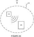
- FIG. 2A is a schematic representation of a wireless power transmission network, 200.
- the wireless power transmission network has a wireless power transmitter, 202, that transmits wireless power, for example via RF power or magnetic induction as described herein, to an EC window 204.
- the EC window 204 also has a photovoltaic power supply.
- Electrochromic window 204 is configured with a receiver that converts the wirelessly transmitted power to electrical energy that is used to operate the EC device in the EC window and optionally window controllers, sensors and the like.
- the electrical energy is a voltage potential used to power the EC device's transitions and/or maintain optical states.
- the EC device will have an associated controller, e.g.
- the EC device can be controlled and managed by an external controller which communicates with the device via a network.
- the input can be manually input by a user, either directly or via wireless communication, or the input can be from an automated heat and/or energy management system of a building of which the EC window is a component.
- the wireless power transmission network is generally defined by area, 206, that is, transmission of power generally is localized to area 206, but not necessarily so.
- Area 206 can define an area where one or more windows reside and where wireless power will be transmitted.
- Transmitter 202 can be outside area 206 in some embodiments (and transmit power into the area) or inside area 206 as depicted in Figure 2 .
- the wireless power receiver resides proximate the IGU of the EC window. Preferably the receiver does not obstruct the view through the EC window.
- a wireless power network as described can contain a plurality of EC windows to which power is supplied wirelessly via one or more transmitters.
- the electrical energy produced via the wireless power can be used to augment a battery supply in the EC window.
- the photovoltaic power supply is used to augment battery charging performed via wireless power transmission.
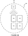
- FIG. 2B is a schematic representation of another wireless power transmission network, 201.
- Network 201 is much like network 200 as described above in relation to Figure 2A , except that the wireless power transmitted from transmitter 202 that is received by a receiver in EC window 204 is used to power not only window 204 but also windows 205. That is, the receiver in a single window is configured to convert wireless power transmissions into electrical energy in order to power more than one EC window, either directly or via a battery or batteries that are charged by the receiver.
- a receiver associated with window 204 converts the wireless power transmissions into electrical energy and transfers the energy via wires to windows 205.
- FIG. 2C is a schematic representation of another wireless power transmission network, 208.
- Network 208 is much like network 200 as described above in relation to Figure 2A , except that the wireless power transmitted from transmitter 202 is not received directly by a receiver in EC window 204, but rather relayed via a power node 210.
- Power node 210 can either relay the power in the same form as that which it received (e.g. via an RF antenna or induction coil) or be configured to change the wireless power and transmit it to the receiver in a form more suited to the (ultimate) requirements of window 204.
- the power node receives the wireless power transmission in one form, either RF or magnetic induction, and transmits wireless power to window 204 in the other of the other of the aforementioned forms.
- power node including: a wireless power transmission receiver; configured to receive wireless power transmissions in one or more forms and convert the transmissions to electrical energy; and a wireless power transmitter configured to convert the electrical energy into wireless power transmissions in said one or more forms.
- the wireless power transmitter is configured to convert the electrical energy into the same form of wireless power transmission than the wireless power receiver is configured to receive. Although the form is the same, there may be, for example, different frequency or polarity used so that the receiver of the power node can distinguish between the wireless transmissions from transmitter 202 and the transmitter of the power node 210.
- the wireless power transmitter is configured to convert the electrical energy into a different form of wireless power transmission than the wireless power receiver is configured to receive.
- FIG. 2D is a schematic representation of another wireless power transmission network, 212.
- Network 212 is much like network 208 as described above in relation to Figure 2C , except that the wireless power transmitted from transmitter 202 is relayed via a power node 210 to a plurality of windows 204.
- power node 210 can either relay the power in the same form as that which it received (e.g. via an RF antenna or induction coil) or be configured to change the wireless power and transmit it to the receiver in a form more suited to the (ultimate) requirements of windows 204.
- transmitter 202 is outside of area 206.
- the power requirements of windows 204 are the same, however the disclosure is not so limited.
- the wireless power transmitted from node 210 can be of a sufficient level so as to satisfy the power requirements of EC windows having different power needs, for example, where components for appropriately converting the wireless power transmissions from power node 210 to electrical energy are part of each window 204's receiver.
- FIG. 2E is a schematic representation of one such wireless power transmission network, 214.
- Network 214 is much like network 212 as described above in relation to Figure 2D , except that the wireless power transmitted from transmitter 202 is relayed via two power nodes, 210 and 216.
- Power node 210 can either relay the power in the same form as that which it received (e.g.
- Power node 216 relays the wireless power in a manner different than power node 210, that is power node 216 is configured to change the wireless power and transmit it to the receiver in window 218 in a form more suited to the (ultimate) requirements of window 218.
- window 218 is configured to supply power to itself and to windows 220 through wiring. Window 218 receives wireless power transmissions from node 216 and the receiver of window 218 converts the wireless power transmission into sufficient power to operate window 218 and windows 220.
- different power nodes can receive the same form of wireless energy, for example from a single transmitter, but relay the wireless energy in different formats for different EC devices (via associated receivers), in this example EC windows having different power requirements.
- transmitter 202 is outside of area 206.
- a single wireless power transmitter transmits a wireless power and each of a plurality of EC windows includes a receiver specifically configured to convert the wireless power to an electrical energy suited for the particular needs of that window.
- each window has an equivalent receiver that converts the wireless power into the same electrical energy, but the electrical energy is converted to the particular needs of the window by one or more electronic components, in communication with the receiver, for example a rectifier, voltage converter, frequency changer, transformer, or inverter.
- a rectifier for example a rectifier, voltage converter, frequency changer, transformer, or inverter.
- a wireless power transmission network including: i) a wireless power transmitter configured to transmit a wireless power; ii) a power node, configured to receive the wireless power and relay the wireless power; iii) a receiver configured to receive the relayed wireless power and convert the wireless power to an electrical energy; and iv) an EC device configured to receive the electrical energy.
- the EC device is an EC window.
- the power node comprises an RF antenna.
- the power node comprises an induction coil.
- the receiver is an RF receiver.
- the receiver is an induction coil.
- the power node is configured to change the wireless power prior to relaying the wireless power to the EC window, depending on the requirements of the EC window.
- the wireless power network includes a plurality of power nodes wherein each power node is configured to relay power to one or more EC windows, each of the plurality of power nodes configured to relay wireless power according to the requirements of the EC windows comprising receivers corresponding to said each of the plurality of power nodes.
Landscapes
- Engineering & Computer Science (AREA)
- Physics & Mathematics (AREA)
- Power Engineering (AREA)
- Computer Networks & Wireless Communication (AREA)
- Nonlinear Science (AREA)
- Optics & Photonics (AREA)
- Structural Engineering (AREA)
- General Physics & Mathematics (AREA)
- Architecture (AREA)
- Civil Engineering (AREA)
- Electrochromic Elements, Electrophoresis, Or Variable Reflection Or Absorption Elements (AREA)
- Charge And Discharge Circuits For Batteries Or The Like (AREA)
Description
- The invention relates generally to the field of electrochromic (EC) devices coupled with wireless power transmission technology. More specifically the invention relates to EC windows powered by wireless power transmission technology and photovoltaic power supplies.
- Electrochromism is a phenomenon in which a material exhibits a reversible electrochemically-mediated change in an optical property when placed in a different electronic state, typically by being subjected to a voltage change. The optical property is typically one or more of color, transmittance, absorbance, and reflectance. One well known EC material, for example, is tungsten oxide (WO3). Tungsten oxide is a cathodic EC material in which a coloration transition, transparent to blue, occurs by electrochemical reduction. While electrochromism was discovered in the 1960's, EC devices and apparatus and systems containing EC devices have not begun to realize their full commercial potential.
- Electrochromic materials may be incorporated into, for example, windows. One drawback of conventional EC windows is that the power used, although small in amount, requires a hard wired connection to a power source of a building. This creates problems when builders are installing, for example, a large number of windows in an office building. Having to deal with hard wiring required for windows is just another impediment that a builder must deal with in the long list of items necessary to build a modern structure. Also, although EC windows offer an elegant solution in the management of heat zones in a modern building, for example, when controlled by an automated heat and/or energy management system, EC windows that require hard wired power sources create impediments to integration into automated energy management systems. Thus the additional installation costs and risks associated with wires will slow down the adoption of EC windows in new construction and may prevent retrofit applications in many cases because retrofit requires additional installation of wiring infrastructure for the new EC windows.
-
US 6,055,089 A describes a photovoltaic powering and control system for electrochromic windows.US 5,384,653 A describes a stand-alone photovoltaic (PV) powered electrochromic window.JP 2004/012818 A WO 2008/058881 A1 describes an automotive glazing having a non-galvanic contact for an electrical device associated with the glazing. - According to the present invention, there is provided a system according to claim 1 and a method of powering an electrochromic window with an electrochromic device according to
claim 11. - Electrochromic devices, particularly EC windows, powered by wireless power transmission are described. The combination of low-defectivity, highly-reliable EC windows with wireless power transmission is described.
- Scalable EC window technology that integrates wireless power transmission technology to create a wirelessly-powered EC window is described. Such technology may optionally include environmental sensors, wireless control and/or in some aspects photovoltaic power. This enables full benefits of EC window technology to be realized at national level savings of quads of energy and hundreds of tons of carbon annually. New construction will benefit greatly from wirelessly powered EC windows, and there is particular advantage in retrofit applications, where installing wires for replacement windows is problematic.
- Also described herein is an EC device powered by wireless power transmission. The EC device may be an EC window. Wireless power transmission is utilized to provide power to one or more EC device's in an EC window. Wireless power can be used to directly power an EC device in the window or, alternatively, charge an internal battery which powers the EC transitions and/or EC states of the EC device(s) in the window. Wireless power transmission may be received by a receiver that powers more than one EC window. Wireless power can also be used to power other active devices which are part of, or directly support, the EC window: for example, motion sensors, light sensors, heat sensors, moisture sensors, wireless communication sensors and the like. Wireless communication technology can also be used to control the wirelessly powered EC window.
- Wireless power transmission of any suitable type can be used in conjunction with EC windows. Wireless power transmission includes, for example but not limited to, induction, resonance induction, radio frequency power transfer, microwave power transfer and laser power transfer. In one example, power is transmitted to a receiver via radio frequency, and the receiver converts the power into electrical current utilizing polarized waves, for example circularly polarized, elliptically polarized and/or dual polarized waves, and/or various frequencies and vectors. In another example, power is wirelessly transferred via inductive coupling of magnetic fields. In a specific example, power is wirelessly transferred via a first resonator (a coil that converts electrical energy, e.g. AC, running through the coil into a magnetic field), which receives power from an external supply hard wired to the first resonator, and a second resonator (a coil that is coupled to the magnetic field and thereby produces electrical energy via induction), which acts as the receiver by producing an electric current or potential via coupling of the magnetic resonance fields of the first and second resonators. Although embodiments utilizing magnetic induction need not necessarily use resonance coupled magnetic fields, in those that do, near-field resonance from localized evanescent magnetic field patterns is a relatively efficient method of wireless power transfer.
- Also described herein, the window receiver is an RF antenna. In another example the RF antenna converts RF power into an electrical potential used to function the EC device. In another example the receiver is a second resonator which is resonance coupled to a first resonator, configured so that power is transmitted wirelessly from the first resonator to the second resonator. The second resonator converts the wirelessly transferred power into electricity to power the EC window.
- Typically the receiver, whether RF antenna or secondary resonance coil, is located in the frame of the EC window, e.g., near the outer seal of the IGU and/or somewhere in the window frame so as not to obscure the viewable area through the glass of the IGU. Thus, in particular examples, the receiver is of relatively small dimensions. In one example, the receiver is of sufficiently small dimensions that the user of the window may not recognize the receiver as being part of the window, but rather the receiver is hidden from the view of the user.
- Also described herein, the wireless power transmission is carried out via a wireless power transmission network which includes one or more power nodes for transmitting power to window receivers in particular areas. Depending on the building or need, one or more, sometimes several nodes are used to form a network of power nodes which feed power to their respective window receivers. Also described herein, where radio frequency is used to transmit power and there are more than one power node, there are more than one frequency and/or polarization vector used in the power nodes, so that different levels or types of power are transferred from the various nodes to windows having different power needs. In another example, where magnetic induction is used for wireless power transfer, there also are one or more power nodes, but in this embodiment, the power nodes are themselves resonators. For example, a first resonator, which receives power via a power supply, is resonance coupled to a second resonator, and the second resonator is resonance coupled to a third resonator, for example that delivers power to an EC window. In this way, the second resonator acts as a power node in a power transfer network from the first resonator, to the second resonator, to the third resonator, the third resonator acting as the receiver and transmitting power to the EC window via conversion of magnetic field to electrical power.
- Also described herein is a method of powering an EC device, the method including: i) generating and/or transmitting a wireless power to a receiver, said receiver configured to convert the wireless power to electrical energy (e.g., electrical current or potential) used to power the EC device; and ii) delivering the electrical energy to the EC device. In one example, the EC device is an EC window as described above. In another example, i) is performed via RF; in another embodiment, i) is performed via magnetic induction. In one example, the electrical energy from the receiver is used to charge a battery, which in turn is used to power to the EC device(s) of the EC window. In one example, a single window has a wireless power receiver, and the electrical energy created by the receiver is used to power more than one EC window, directly and/or by charging a battery or system of batteries associated with the windows.
- Also disclosed herein is a wireless power transmission network including: i) a wireless power transmitter configured to transmit a wireless power; ii) a power node, configured to receive the wireless power and relay the wireless power; iii) a receiver configured to receive the relayed wireless power and convert the wireless power to an electrical energy; and, iv) an EC device configured to receive the electrical energy to power a transition between optical states and/or maintain an optical state. The electrical energy can be received by the EC device either directly or indirectly. In one example, the electrical energy is received directly from the receiver, in another example, the electrical energy is directed from the receiver to a battery, and then to the EC device. In one example, the EC device is part of an EC window.
- Also disclosed herein, the EC device receives some of its electrical energy from a wireless power source as described above and additional electrical energy from a photovoltaic source that may optionally be integrated with the EC device (e.g., in or near an IGU, for example in a window frame). Such systems may require no wiring to power the EC device and associated controller, sensors and the like.
- These and other features and advantages will be described in further detail below, with reference to the associated drawings.
- The following detailed description can be more fully understood when considered in conjunction with the drawings in which:
-
Figure 1 depicts EC window fabrication including a wireless power receiver. -
Figures 2A-2E are schematic representations of wireless power transmission networks as described herein. - In the broadest sense, the disclosure relates to an EC device powered by a wireless power transmission source. In more specific examples, EC windows are powered by wireless power sources. Wireless power transmission is particularly well suited for supplying EC windows, because EC windows typically function using low potentials, on the order of a few volts to transition an EC device and/or maintain the device's optical state. Typically, EC windows are transitioned only a few times per day. Also, wireless power transmission can be used to charge an associated battery, so that indirect powering of one or more EC windows via wireless power transmission is achieved.
- Installing windows with wires entails further considerations for the architect and builder, and in retrofit applications wires are particularly problematic due to the need for additional wiring infrastructure that was not previously installed in the building. The combination of these advanced technologies, wireless power transmission and EC windows, solves these problems and provides a synergy that saves energy, as well as time and money that would be spent integrating hard wire electrical connections of EC windows.
- Dynamic, EC, insulated glass units (IGU's) for commercial and residential windows change light transmission properties in response to a small voltage, allowing control of the amount of light and heat passing through the windows. The EC device changes between a transparent "clear or bleached" state and a darkened (light and/or heat blocking) state using small potentials and can maintain optical states with even less power. Dynamic EC windows can filter the amount of light passing through the window, in one aspect providing visibility even in its darkened state and thus preserving visual contact with the outside environment while saving energy by, for example, blocking out heat generating solar rays during hot weather or keeping valuable heat in a building due to their insulating properties during cold weather.
- One example of such dynamic windows are low-defectivity, highly-reliable EC windows which include solid-state EC stack materials. Such all solid-state and inorganic EC devices, methods of fabricating them, and defectivity criterion are described in more detail in
U.S. Patent Application, serial number 12/645,111, entitled, "Fabrication of Low-Defectivity Electrochromic Devices," filed on December 22, 2009 and naming Mark Kozlowski et al. U.S. Patent Application, serial number 12/645,159, entitled, "Electrochromic Devices," filed on December 22, 2009 and naming Zhongchun Wang et al. U.S. Patent Applications, serial numbers 12/772,055 and12/772,075, each filed on April 30, 2010 U.S. Patent Applications, serial numbers 12/814,277 and12/814,279, each filed on June 11, 2010 - each of the four applications is entitled "Electrochromic Devices," each names Zhongchun Wang et al.
Wireless power transmission is the process that takes place where electrical energy is transmitted from a power source to an electrical load, without interconnecting wires. In the broadest sense, electrical current can pass through the environment, be it air, water or solid objects without the need for wires. But more useful (controlled) forms of wireless power transmission exist, for example transmitting power via RF, magnetic induction, lasers or microwave energy. Wireless transmission finds particular use in applications where instantaneous or continuous energy transfer is needed, but interconnecting wires are inconvenient, problematic, hazardous, or impossible. Wireless power transfer may be inductive, including electrodynamic induction, or based upon other known energy transfer mediums such as radio frequency (RF), microwaves and lasers. - In some embodiments, power is transferred via RF, and transformed into electrical potential or current by a receiver in electrical communication with an EC device, particularly an EC window. One particularly useful method of transferring power via RF is described in
US Patent Publication 2007/0191074 ,from application 11/699,148 filed January 29th, 2007, entitled "Power Transmission Network and Method," by Daniel W. Harrist, et al. - In other embodiments, power is transferred via magnetic induction using a first resonator powered by an external power supply and a second resonator which converts the magnetic field energy created by the first resonator into power that supplies the EC device of the EC window. One particularly useful method of transferring power via magnetic induction is described in
US Patent Publication 2007/0222542 , fromapplication 11/481,077 filed July 5th, 2006, entitled "Wireless Non-radiative Energy Transfer," by John Joannapoulos, et al.US Patent 7,382,636, filed October 14th, 2005, entitled "System and Method for Powering a Load," by David Baarman, et al. EC windows described herein can incorporate such methods of controlling wireless power transmission. - Certain embodiments include more than one wireless power transmission source, that is, the invention is not limited to embodiments where a single wireless power transmission source is used. For example, in embodiments were a wireless power transmission network is used, one wireless power transmission method, for example RF power transmission, is used in part of the network, while another method, for example, magnetic induction, is used in another part of the network.
- One aspect of the invention is a system comprising an EC window powered by a wireless power transmission source and a photovoltaic power supply as defined in claim 1. In one embodiment, the EC window can be of any useful size, e.g., in automotive use, such as in a sunroof or a rear view mirror where wiring is inconvenient, for example having to pass through a windshield of a car. In one embodiment, the EC window uses architectural scale glass as a substrate for the EC device of the window. Architectural glass is glass that is used as a building material. Architectural glass is typically used in commercial buildings, but may also be used in residential buildings and typically, but not necessarily, separates an indoor environment from an outdoor environment. Architectural glass is at least 20 inches by 20 inches, and can be as large as about 80 inches by 80 inches. In some embodiments, the EC device is all solid state and inorganic. The window will have a receiver, for example an RF receiver or resonator, as part of a window assembly.
-
Figure 1 depicts an EC window fabrication, 100, where the window assembly includes a receiver, 135, for receiving wireless power transmissions, converting the transmissions to an electrical energy and powering an EC device of the window with the electrical energy, either directly or indirectly, for example, via powering the EC device directly or charging a battery that is used to power the EC window. An EC pane, 105, having an EC device (not shown, but for example on surface A) and bus bars, 110, which power the EC device, is matched with another glass pane, 115. During fabrication of IGU, 125, a separator, 120, is sandwiched in between and registered withsubstrates IGU 125 has an associated interior space defined by the faces of the substrates in contact withseparator 120 and the surfaces of the interior perimeter ofseparator 120.Separator 120 is typically a sealing separator, that is, includes a spacer and sealing between the spacer and each substrate where they adjoin in order to hermetically seal the interior region and thus protect the interior from moisture and the like. Typically, once the glass panes are sealed to the separator, secondary sealing may be applied around the outer perimeter edgesseparator 120 of the IGU in order to impart not only further sealing from the ambient, but also further structural rigidity to the IGU. The IGU is supported by a frame to create a window assembly, 130. A cut out of the window frame is shown to revealwireless power receiver 135 which includes an antennae in this example.Receiver 135 is proximate the IGU, in this example, inside the frame ofwindow assembly 130. The wireless power transmission receiver may be a component of a window controller. - In one embodiment, the wireless power transmission source transmits power via a radio frequency. In such embodiments, the EC window includes a radio frequency receiver, where the radio frequency receiver configured to convert the radio frequency to electrical energy (e.g., an electrical current or potential) used to power an EC device in the EC window. Powering the EC device includes at least one of powering an optical transition or an optical state of the EC device. In one embodiment, the radio frequency receiver resides in or near the IGU of the EC window. For example, the receiver can be in the window frame that supports the IGU, in an area near the spacer that separates the glass panes of the IGU, or both. Preferably, but not necessarily, the receiver does not obscure the viewable area of the IGU, for example, as depicted in
Figure 1 . - In another embodiment, power is wirelessly transferred via inductive coupling of magnetic fields. In general terms, a primary coil (that converts electrical energy, e.g. AC, running through the coil into a magnetic field) supplied by a power source generates a magnetic field and a secondary coil is coupled to the magnetic field and thereby produces electrical energy via induction. The electrical energy produced by the secondary coil is used to power the EC device, in particular embodiments an EC device of an EC window. In a specific embodiment where resonance coupled magnetic energy is utilized, power is wirelessly transferred via a first resonator, which receives power from an external supply hard wired to the first resonator, and a second resonator, which acts as the receiver by producing an electric current via coupling of the magnetic resonance fields of the first and second resonators. Although embodiments utilizing magnetic induction need not necessarily use resonance coupled magnetic fields, in those that do, near-field resonance from localized evanescent magnetic field patterns is a relatively efficient method of wireless power transfer.
- In one embodiment, the receiver, whether RF antenna or resonance coil, is located proximate the IGU of the EC window, e.g., near the IGU seal or the window frame so as not to obscure the viewable area through the glass of the IGU. Thus, in particular embodiments, the receiver is of relatively small dimensions. "Small dimensions" means, for example, that the receiver occupies not more than about 5% of the viewable area of the EC window. In one embodiment, the receiver occupies none of the viewable area of the EC window, that is, the receiver is of sufficiently small dimensions that the user of the window may not recognize the receiver as being part of the window, but rather the receiver is hidden from the view of the user, e.g. housed in the frame of the window. In one embodiment, where the receiver is housed in seal area of the IGU, the frame of the window can have one or more access ports for servicing the receiver or the receiver can be sealed permanently in the window frame. There may also be ports and/or materials transparent to the wireless power transmission, so that the receiver can properly receive the wireless power transmissions without interference from the window frame material.
- In particular embodiments, there is a controller, for example a microprocessor, that regulates the potential applied to the EC device and may optionally control other functions (alone or combined with other microprocessors) such as recharging a battery used to function the window, wirelessly communicating with a remote control, such as a hand held, an automated heat and/or energy management system that communicates wirelessly with the window controller.
- In one embodiment, the wireless power transmission is carried out via a network which includes one or more power nodes for transmitting power to window receivers in particular areas. Wireless power transmission networks described herein can use RF, magnetic induction or both, depending on the need. Depending on the building, one or more, sometimes several nodes are used to form a network of power nodes which feed power to their respective window receivers. In one embodiment, where radio frequency is used to transmit power and there are more than one power node, there are more than one frequency and/or polarization vector used in the power nodes, so that different levels or types of power are transferred from the various nodes to windows having different power needs.
- In one embodiment, where magnetic induction is used for wireless power transfer, there also are one or more power nodes, but in this embodiment, the power nodes are themselves resonators. For example, in one embodiment, a first resonator, which receives power via a power supply, is resonance coupled to a second resonator, and the second resonator is resonance coupled to a third resonator, for example that delivers power to an EC window. In this way, the second resonator acts as a power node in a power transfer network from the first resonator, to the second resonator, to the third resonator, the third resonator acting as the receiver and transmitting power to the EC window via conversion of magnetic field to electrical power. In this way, near field magnetic energy can span longer distances in order to suit the needs of the particular building's EC windows.
- Also disclosed is a method of powering an EC device, the method comprising: i) generating a wireless power; ii) transmitting the wireless power to a receiver; said receiver configured to convert the wireless power to an electrical energy used to power the EC device; and iii) delivering the electrical energy (e.g., current or potential) to the EC device and/or a battery used to power the EC device. In one example, the EC device is an EC window. In other examples, generating the wireless power is performed via a wireless power transmitter that transmits power via a radio frequency and the electrical energy is a voltage potential. In another example, generating the wireless power is performed via a wireless power transmitter that transmits power via magnetic induction, in a more particular example, resonance coupled magnetic induction. In other particular examples, ii) and iii) are accomplished via at least one of the wireless power transmission networks as described above. In one particular exampleof the above described examples, the EC device is part of an EC pane of an EC window. In an even more particular example, the EC pane is of architectural glass scale. In another example, at least one of i), ii) and iii) are performed via wireless communication. One exampleincludes using the electrical energy created by the receiver's conversion of wireless power transmission for charging a battery that is used to power the EC device.
-
Figure 2A is a schematic representation of a wireless power transmission network, 200. The wireless power transmission network has a wireless power transmitter, 202, that transmits wireless power, for example via RF power or magnetic induction as described herein, to anEC window 204. TheEC window 204 also has a photovoltaic power supply.Electrochromic window 204 is configured with a receiver that converts the wirelessly transmitted power to electrical energy that is used to operate the EC device in the EC window and optionally window controllers, sensors and the like. In one embodiment, the electrical energy is a voltage potential used to power the EC device's transitions and/or maintain optical states. Typically, the EC device will have an associated controller, e.g. a microprocessor that controls and manages the device depending on the input. Additionally, the EC device can be controlled and managed by an external controller which communicates with the device via a network. The input can be manually input by a user, either directly or via wireless communication, or the input can be from an automated heat and/or energy management system of a building of which the EC window is a component. - The wireless power transmission network is generally defined by area, 206, that is, transmission of power generally is localized to
area 206, but not necessarily so.Area 206 can define an area where one or more windows reside and where wireless power will be transmitted.Transmitter 202 can be outsidearea 206 in some embodiments (and transmit power into the area) or insidearea 206 as depicted inFigure 2 . In one embodiment, the wireless power receiver resides proximate the IGU of the EC window. Preferably the receiver does not obstruct the view through the EC window. One of ordinary skill in the art would appreciate that a wireless power network as described can contain a plurality of EC windows to which power is supplied wirelessly via one or more transmitters. Also, the electrical energy produced via the wireless power can be used to augment a battery supply in the EC window. In one embodiment, the photovoltaic power supply is used to augment battery charging performed via wireless power transmission. -
Figure 2B is a schematic representation of another wireless power transmission network, 201.Network 201 is much likenetwork 200 as described above in relation toFigure 2A , except that the wireless power transmitted fromtransmitter 202 that is received by a receiver inEC window 204 is used to power not onlywindow 204 but alsowindows 205. That is, the receiver in a single window is configured to convert wireless power transmissions into electrical energy in order to power more than one EC window, either directly or via a battery or batteries that are charged by the receiver. In this example, a receiver associated withwindow 204 converts the wireless power transmissions into electrical energy and transfers the energy via wires towindows 205. This has the advantage of not relying on a receiver for each window, and, although some wiring is used, it is localized to the window installation area, providing electrical communication between the windows, rather than having to be run throughout a building. Also, since EC windows do not have high power requirements, this configuration is practical. -
Figure 2C is a schematic representation of another wireless power transmission network, 208.Network 208 is much likenetwork 200 as described above in relation toFigure 2A , except that the wireless power transmitted fromtransmitter 202 is not received directly by a receiver inEC window 204, but rather relayed via apower node 210.Power node 210 can either relay the power in the same form as that which it received (e.g. via an RF antenna or induction coil) or be configured to change the wireless power and transmit it to the receiver in a form more suited to the (ultimate) requirements ofwindow 204. In one example, the power node receives the wireless power transmission in one form, either RF or magnetic induction, and transmits wireless power towindow 204 in the other of the other of the aforementioned forms. One example is power node including: a wireless power transmission receiver; configured to receive wireless power transmissions in one or more forms and convert the transmissions to electrical energy; and a wireless power transmitter configured to convert the electrical energy into wireless power transmissions in said one or more forms. In one example, the wireless power transmitter is configured to convert the electrical energy into the same form of wireless power transmission than the wireless power receiver is configured to receive. Although the form is the same, there may be, for example, different frequency or polarity used so that the receiver of the power node can distinguish between the wireless transmissions fromtransmitter 202 and the transmitter of thepower node 210. In one example, the wireless power transmitter is configured to convert the electrical energy into a different form of wireless power transmission than the wireless power receiver is configured to receive. -
Figure 2D is a schematic representation of another wireless power transmission network, 212.Network 212 is much likenetwork 208 as described above in relation toFigure 2C , except that the wireless power transmitted fromtransmitter 202 is relayed via apower node 210 to a plurality ofwindows 204. Again,power node 210 can either relay the power in the same form as that which it received (e.g. via an RF antenna or induction coil) or be configured to change the wireless power and transmit it to the receiver in a form more suited to the (ultimate) requirements ofwindows 204. In this example,transmitter 202 is outside ofarea 206. In this example, the power requirements ofwindows 204 are the same, however the disclosure is not so limited. That is, the wireless power transmitted fromnode 210 can be of a sufficient level so as to satisfy the power requirements of EC windows having different power needs, for example, where components for appropriately converting the wireless power transmissions frompower node 210 to electrical energy are part of eachwindow 204's receiver. - In one example fulfilling the varying power requirements of different windows within a wireless power transmission network is accomplished using different power nodes for windows with different power needs. The power relayed from each node can be, for example, of different power level and/or transmitted in a different way.
Figure 2E is a schematic representation of one such wireless power transmission network, 214.Network 214 is much likenetwork 212 as described above in relation toFigure 2D , except that the wireless power transmitted fromtransmitter 202 is relayed via two power nodes, 210 and 216.Power node 210 can either relay the power in the same form as that which it received (e.g. via an RF antenna or induction coil) or be configured to change the wireless power and transmit it to the receiver (in window 204) in a form more suited to the (ultimate) requirements ofwindow 204.Power node 216 relays the wireless power in a manner different thanpower node 210, that ispower node 216 is configured to change the wireless power and transmit it to the receiver inwindow 218 in a form more suited to the (ultimate) requirements ofwindow 218. In this example,window 218 is configured to supply power to itself and towindows 220 through wiring.Window 218 receives wireless power transmissions fromnode 216 and the receiver ofwindow 218 converts the wireless power transmission into sufficient power to operatewindow 218 andwindows 220. Thus, as described herein, different power nodes can receive the same form of wireless energy, for example from a single transmitter, but relay the wireless energy in different formats for different EC devices (via associated receivers), in this example EC windows having different power requirements. In this example,transmitter 202 is outside ofarea 206. In a specific example, a single wireless power transmitter transmits a wireless power and each of a plurality of EC windows includes a receiver specifically configured to convert the wireless power to an electrical energy suited for the particular needs of that window. In another example, each window has an equivalent receiver that converts the wireless power into the same electrical energy, but the electrical energy is converted to the particular needs of the window by one or more electronic components, in communication with the receiver, for example a rectifier, voltage converter, frequency changer, transformer, or inverter. - Also disclosed is a wireless power transmission network including: i) a wireless power transmitter configured to transmit a wireless power; ii) a power node, configured to receive the wireless power and relay the wireless power; iii) a receiver configured to receive the relayed wireless power and convert the wireless power to an electrical energy; and iv) an EC device configured to receive the electrical energy. In one example, the EC device is an EC window. In another example the power node comprises an RF antenna. In one example, the power node comprises an induction coil. In another example the receiver is an RF receiver. In another example, the receiver is an induction coil. In other examples, the power node is configured to change the wireless power prior to relaying the wireless power to the EC window, depending on the requirements of the EC window. In some examples, the wireless power network includes a plurality of power nodes wherein each power node is configured to relay power to one or more EC windows, each of the plurality of power nodes configured to relay wireless power according to the requirements of the EC windows comprising receivers corresponding to said each of the plurality of power nodes.
- Although the foregoing invention has been described in some detail to facilitate understanding, the described embodiments are to be considered illustrative and not limiting. It will be apparent to one of ordinary skill in the art that certain changes and modifications can be practiced within the scope of the appended claims.
Claims (16)
- A system (200, 201, 208, 212, 214) comprising:a receiver configured to receive wireless power transmissions from a wireless power transmitter (202) and convert the wireless power transmissions into electrical energy;a photovoltaic power supply configured to generate additional electrical energy; andan electrochromic window (125, 204, 205, 206, 218, 220) including an electrochromic device configured to receive and be powered by the electrical energy from the receiver and the additional electrical energy from the photovoltaic power supply;wherein the electrochromic device is configured to be controlled to transition between a clear state and a darkened state.
- The system (200, 201, 208, 212, 214) of claim 1,further comprising a battery configured to deliver power to the electrochromic device,optionally wherein the photovoltaic power supply is configured to augment battery charging performed via wireless power transmission.
- The system (200, 201, 208, 212, 214) of claim 1, wherein the electrochromic window (125, 204, 205, 206, 218, 220) is in the form of an insulated glass unit, optionally wherein the photovoltaic power supply is in or near the insulated glass unit.
- The system (200, 201, 208, 212, 214) of claim 1, wherein the wireless power transmissions are based on magnetic induction, radio frequency, microwave energy, or laser.
- The system (200, 205, 206, 218, 220) of claim 1, wherein:(i) the system has no wiring for supplying power to the electrochromic window (125, 204, 205, 206, 218, 220) of the system (200, 205, 206, 218, 220); or(ii) the system further comprises a controller configured to regulate a voltage potential applied to the electrochromic device, wherein the controller is configured: to communicate wirelessly with a heat and/or energy management system of a building; or to control the electrochromic device based on input from a heat and/or energy management system of a building.
- The system (200, 205, 206, 218, 220) of claim 1, further comprising one or more sensors, optionally wherein the one or more sensors include one or more of a motion sensor, a light sensor, a heat sensor and a moisture sensor.
- The system (200, 205, 206, 218, 220) of claim 1, wherein the electrochromic device is a solid state and inorganic stack of material layers disposed on a glass substrate.
- The system (200, 205, 206, 218, 220) of claim 1, further comprising a microprocessor configured to regulate a voltage potential applied to the electrochromic device.
- The system (200, 205, 206, 218, 220) of claim 8,wherein the microprocessor, alone or combined with other microprocessors, is further configured to control recharging a battery configured to deliver power to the electrochromic device and/or wireless communications with a remote control,optionally wherein the remote control is a hand held device or part of a heat and/or energy management system.
- The system of claim 2, wherein the receiver is configured to deliver electrical energy converted from wireless power transmissions to the electrochromic device to augment power delivered to the electrochromic device by the battery or the photovoltaic power supply.
- A method of powering an electrochromic window (125, 204, 205, 206, 218, 220) with an electrochromic device, the method comprising:transmitting, at a wireless power transmitter (202), wireless power transmissions;receiving, at a receiver, the wireless power transmissions andconverting the wireless power transmissions into electrical energy;generating additional electrical energy for the electrochromic window (125, 204, 205, 206, 218, 220) using a photovoltaic power supply;delivering the electrical energy and the additional electrical energy to the electrochromic device to power the electrochromic device; andcontrolling an optical transition between a clear state and a darkened state in the electrochromic device.
- The method of claim 11, wherein a controller, which is configured to regulate a voltage potential applied to the electrochromic device, controls the optical transition based on input from an automated heat and/or energy management system of a building having the electrochromic window (125, 204, 205, 206, 218, 220).
- The method of claim 11, further comprising delivering power to the electrochromic device from a battery in the electrochromic window (125, 204, 205, 206, 218, 220), optionally further comprising augmenting charging of the battery performed via wireless power transmission using power generated by the photovoltaic power supply.
- The method of claim 11, wherein:(i) the electrochromic window (125, 204, 205, 206, 218, 220) is in the form of an insulated glass unit; or(ii) the electrochromic device comprises a solid-state electrochromic stack of materials disposed on a glass substrate.
- The method of claim 11, wherein the wireless power transmissions are transmitted via magnetic induction, radio frequency, microwave energy or laser.
- The method of claim 15, further comprising charging a battery using power from both the photovoltaic power supply and the wireless transmission power supply.
Priority Applications (1)
| Application Number | Priority Date | Filing Date | Title |
|---|---|---|---|
| EP21209968.3A EP3995885A1 (en) | 2009-12-22 | 2010-12-17 | Wireless powered electrochromic windows |
Applications Claiming Priority (3)
| Application Number | Priority Date | Filing Date | Title |
|---|---|---|---|
| US28931909P | 2009-12-22 | 2009-12-22 | |
| PCT/US2010/061091 WO2011087726A2 (en) | 2009-12-22 | 2010-12-17 | Wireless powered electrochromic windows |
| EP10843504.1A EP2517332B1 (en) | 2009-12-22 | 2010-12-17 | Wireless powered electrochromic windows |
Related Parent Applications (2)
| Application Number | Title | Priority Date | Filing Date |
|---|---|---|---|
| EP10843504.1A Division-Into EP2517332B1 (en) | 2009-12-22 | 2010-12-17 | Wireless powered electrochromic windows |
| EP10843504.1A Division EP2517332B1 (en) | 2009-12-22 | 2010-12-17 | Wireless powered electrochromic windows |
Related Child Applications (1)
| Application Number | Title | Priority Date | Filing Date |
|---|---|---|---|
| EP21209968.3A Division EP3995885A1 (en) | 2009-12-22 | 2010-12-17 | Wireless powered electrochromic windows |
Publications (2)
| Publication Number | Publication Date |
|---|---|
| EP3425450A1 EP3425450A1 (en) | 2019-01-09 |
| EP3425450B1 true EP3425450B1 (en) | 2021-11-24 |
Family
ID=44150037
Family Applications (3)
| Application Number | Title | Priority Date | Filing Date |
|---|---|---|---|
| EP18189681.2A Active EP3425450B1 (en) | 2009-12-22 | 2010-12-17 | Wireless powered electrochromic windows |
| EP21209968.3A Withdrawn EP3995885A1 (en) | 2009-12-22 | 2010-12-17 | Wireless powered electrochromic windows |
| EP10843504.1A Active EP2517332B1 (en) | 2009-12-22 | 2010-12-17 | Wireless powered electrochromic windows |
Family Applications After (2)
| Application Number | Title | Priority Date | Filing Date |
|---|---|---|---|
| EP21209968.3A Withdrawn EP3995885A1 (en) | 2009-12-22 | 2010-12-17 | Wireless powered electrochromic windows |
| EP10843504.1A Active EP2517332B1 (en) | 2009-12-22 | 2010-12-17 | Wireless powered electrochromic windows |
Country Status (4)
| Country | Link |
|---|---|
| US (5) | US9081246B2 (en) |
| EP (3) | EP3425450B1 (en) |
| JP (5) | JP5805658B2 (en) |
| WO (1) | WO2011087726A2 (en) |
Families Citing this family (170)
| Publication number | Priority date | Publication date | Assignee | Title |
|---|---|---|---|---|
| US8514476B2 (en) | 2008-06-25 | 2013-08-20 | View, Inc. | Multi-pane dynamic window and method for making same |
| US9007674B2 (en) | 2011-09-30 | 2015-04-14 | View, Inc. | Defect-mitigation layers in electrochromic devices |
| US9664974B2 (en) | 2009-03-31 | 2017-05-30 | View, Inc. | Fabrication of low defectivity electrochromic devices |
| US11342791B2 (en) | 2009-12-22 | 2022-05-24 | View, Inc. | Wirelessly powered and powering electrochromic windows |
| US20130271813A1 (en) | 2012-04-17 | 2013-10-17 | View, Inc. | Controller for optically-switchable windows |
| US10303035B2 (en) | 2009-12-22 | 2019-05-28 | View, Inc. | Self-contained EC IGU |
| WO2016085964A1 (en) * | 2014-11-25 | 2016-06-02 | View, Inc. | Window antennas |
| US10747082B2 (en) | 2009-12-22 | 2020-08-18 | View, Inc. | Onboard controller for multistate windows |
| US11137659B2 (en) | 2009-12-22 | 2021-10-05 | View, Inc. | Automated commissioning of controllers in a window network |
| US11314139B2 (en) | 2009-12-22 | 2022-04-26 | View, Inc. | Self-contained EC IGU |
| US8213074B1 (en) | 2011-03-16 | 2012-07-03 | Soladigm, Inc. | Onboard controller for multistate windows |
| EP3425450B1 (en) * | 2009-12-22 | 2021-11-24 | View, Inc. | Wireless powered electrochromic windows |
| US11205926B2 (en) * | 2009-12-22 | 2021-12-21 | View, Inc. | Window antennas for emitting radio frequency signals |
| US20210063836A1 (en) | 2017-04-26 | 2021-03-04 | View, Inc. | Building network |
| US10690540B2 (en) | 2015-10-06 | 2020-06-23 | View, Inc. | Multi-sensor having a light diffusing element around a periphery of a ring of photosensors |
| US11630366B2 (en) | 2009-12-22 | 2023-04-18 | View, Inc. | Window antennas for emitting radio frequency signals |
| US11592723B2 (en) | 2009-12-22 | 2023-02-28 | View, Inc. | Automated commissioning of controllers in a window network |
| US11732527B2 (en) | 2009-12-22 | 2023-08-22 | View, Inc. | Wirelessly powered and powering electrochromic windows |
| US20120235474A1 (en) * | 2010-09-14 | 2012-09-20 | Joseph Mannino | Windshield embedded power coil for wireless charging |
| US12496809B2 (en) | 2010-11-08 | 2025-12-16 | View Operating Corporation | Electrochromic window fabrication methods |
| US9958750B2 (en) | 2010-11-08 | 2018-05-01 | View, Inc. | Electrochromic window fabrication methods |
| US8164818B2 (en) | 2010-11-08 | 2012-04-24 | Soladigm, Inc. | Electrochromic window fabrication methods |
| US10180606B2 (en) | 2010-12-08 | 2019-01-15 | View, Inc. | Connectors for smart windows |
| US8643933B2 (en) * | 2011-12-14 | 2014-02-04 | View, Inc. | Connectors for smart windows |
| CN112731720A (en) | 2010-12-08 | 2021-04-30 | 唯景公司 | Improved partition plate of insulating glass device |
| US9442339B2 (en) | 2010-12-08 | 2016-09-13 | View, Inc. | Spacers and connectors for insulated glass units |
| US10571772B2 (en) | 2011-01-11 | 2020-02-25 | Ajjer, Llc | Added feature electrooptical devices and automotive components |
| US10935865B2 (en) | 2011-03-16 | 2021-03-02 | View, Inc. | Driving thin film switchable optical devices |
| US10989977B2 (en) | 2011-03-16 | 2021-04-27 | View, Inc. | Onboard controller for multistate windows |
| US9645465B2 (en) | 2011-03-16 | 2017-05-09 | View, Inc. | Controlling transitions in optically switchable devices |
| US11415949B2 (en) | 2011-03-16 | 2022-08-16 | View, Inc. | Security event detection with smart windows |
| US12105394B2 (en) | 2011-03-16 | 2024-10-01 | View, Inc. | Commissioning window networks |
| US8254013B2 (en) | 2011-03-16 | 2012-08-28 | Soladigm, Inc. | Controlling transitions in optically switchable devices |
| US11054792B2 (en) | 2012-04-13 | 2021-07-06 | View, Inc. | Monitoring sites containing switchable optical devices and controllers |
| US9454055B2 (en) | 2011-03-16 | 2016-09-27 | View, Inc. | Multipurpose controller for multistate windows |
| US10175549B2 (en) | 2011-03-16 | 2019-01-08 | View, Inc. | Connectors for smart windows |
| US11822202B2 (en) | 2011-03-16 | 2023-11-21 | View, Inc. | Controlling transitions in optically switchable devices |
| US10989976B2 (en) | 2011-03-16 | 2021-04-27 | View, Inc. | Commissioning window networks |
| US11630367B2 (en) | 2011-03-16 | 2023-04-18 | View, Inc. | Driving thin film switchable optical devices |
| US8705162B2 (en) | 2012-04-17 | 2014-04-22 | View, Inc. | Controlling transitions in optically switchable devices |
| US9412290B2 (en) | 2013-06-28 | 2016-08-09 | View, Inc. | Controlling transitions in optically switchable devices |
| US9030725B2 (en) | 2012-04-17 | 2015-05-12 | View, Inc. | Driving thin film switchable optical devices |
| US11703814B2 (en) | 2011-03-16 | 2023-07-18 | View, Inc. | Security event detection with smart windows |
| US9778532B2 (en) | 2011-03-16 | 2017-10-03 | View, Inc. | Controlling transitions in optically switchable devices |
| US12498609B2 (en) | 2011-03-16 | 2025-12-16 | View Operating Corporation | Commissioning window networks |
| CN103987909B (en) | 2011-10-21 | 2017-03-22 | 唯景公司 | MITIGATING THERMAL SHOCK IN TINTABLE WINDOWs |
| US10295880B2 (en) | 2011-12-12 | 2019-05-21 | View, Inc. | Narrow pre-deposition laser deletion |
| US12321075B2 (en) | 2011-12-12 | 2025-06-03 | View Operating Corporation | Electrochromic laminates |
| US11865632B2 (en) | 2011-12-12 | 2024-01-09 | View, Inc. | Thin-film devices and fabrication |
| US10802371B2 (en) | 2011-12-12 | 2020-10-13 | View, Inc. | Thin-film devices and fabrication |
| US10606142B2 (en) | 2011-12-12 | 2020-03-31 | View, Inc. | Thin-film devices and fabrication |
| US11048137B2 (en) | 2011-12-12 | 2021-06-29 | View, Inc. | Thin-film devices and fabrication |
| KR20200035328A (en) * | 2011-12-12 | 2020-04-02 | 뷰, 인크. | Thin-film devices and fabrication |
| US10739658B2 (en) | 2011-12-12 | 2020-08-11 | View, Inc. | Electrochromic laminates |
| US12403676B2 (en) | 2011-12-12 | 2025-09-02 | View Operating Corporation | Thin-film devices and fabrication |
| US12061402B2 (en) | 2011-12-12 | 2024-08-13 | View, Inc. | Narrow pre-deposition laser deletion |
| US11719039B2 (en) | 2011-12-14 | 2023-08-08 | View, Inc. | Connectors for smart windows |
| US8976440B2 (en) | 2012-02-03 | 2015-03-10 | Itn Energy Systems, Inc. | Autonomous electrochromic assembly |
| US9341912B2 (en) | 2012-03-13 | 2016-05-17 | View, Inc. | Multi-zone EC windows |
| US12153320B2 (en) | 2012-03-13 | 2024-11-26 | View, Inc. | Multi-zone EC windows |
| US11950340B2 (en) | 2012-03-13 | 2024-04-02 | View, Inc. | Adjusting interior lighting based on dynamic glass tinting |
| US11635666B2 (en) | 2012-03-13 | 2023-04-25 | View, Inc | Methods of controlling multi-zone tintable windows |
| US12578609B2 (en) | 2012-03-13 | 2026-03-17 | View Operating Corporation | Methods of controlling multi-zone tintable windows |
| US11300848B2 (en) | 2015-10-06 | 2022-04-12 | View, Inc. | Controllers for optically-switchable devices |
| US11674843B2 (en) | 2015-10-06 | 2023-06-13 | View, Inc. | Infrared cloud detector systems and methods |
| US10503039B2 (en) | 2013-06-28 | 2019-12-10 | View, Inc. | Controlling transitions in optically switchable devices |
| WO2017007841A1 (en) | 2015-07-08 | 2017-01-12 | View, Inc. | Power management for electrochromic window networks |
| EP3223532B1 (en) | 2012-04-13 | 2019-10-09 | View, Inc. | Applications for controlling optically switchable devices |
| US12619118B2 (en) | 2012-04-13 | 2026-05-05 | View Operating Corporation | Controlling transitions in optically switchable devices |
| US9638978B2 (en) | 2013-02-21 | 2017-05-02 | View, Inc. | Control method for tintable windows |
| US12400651B2 (en) | 2012-04-13 | 2025-08-26 | View Operating Corporation | Controlling optically-switchable devices |
| US10048561B2 (en) | 2013-02-21 | 2018-08-14 | View, Inc. | Control method for tintable windows |
| US10964320B2 (en) | 2012-04-13 | 2021-03-30 | View, Inc. | Controlling optically-switchable devices |
| KR102369491B1 (en) * | 2012-04-17 | 2022-03-02 | 뷰, 인크. | Controller for optically-switchable windows |
| US11255120B2 (en) | 2012-05-25 | 2022-02-22 | View, Inc. | Tester and electrical connectors for insulated glass units |
| WO2014032023A1 (en) | 2012-08-23 | 2014-02-27 | View, Inc. | Photonic-powered ec devices |
| US12372846B2 (en) | 2013-02-21 | 2025-07-29 | View Operating Corporation | Control methods and systems using external 3D modeling and schedule-based computing |
| US12422725B2 (en) | 2013-02-21 | 2025-09-23 | View Operating Corporation | Control methods and systems using outside temperature as a driver for changing window tint states |
| US11719990B2 (en) | 2013-02-21 | 2023-08-08 | View, Inc. | Control method for tintable windows |
| US11966142B2 (en) | 2013-02-21 | 2024-04-23 | View, Inc. | Control methods and systems using outside temperature as a driver for changing window tint states |
| US11960190B2 (en) | 2013-02-21 | 2024-04-16 | View, Inc. | Control methods and systems using external 3D modeling and schedule-based computing |
| PL2971423T3 (en) * | 2013-03-15 | 2020-09-21 | Oran Palmach Zova Agricultural Collective Corporation Ltd. | A double-pane module with an image producing device for use in a structure |
| US12353111B2 (en) | 2013-06-28 | 2025-07-08 | View Operating Corporation | Controlling transitions in optically switchable devices |
| US12061404B2 (en) | 2013-06-28 | 2024-08-13 | View, Inc. | Controlling transitions in optically switchable devices |
| US9885935B2 (en) | 2013-06-28 | 2018-02-06 | View, Inc. | Controlling transitions in optically switchable devices |
| US9606409B2 (en) | 2013-09-13 | 2017-03-28 | Itn Energy Systems Inc. | Electrochromic window insert assembly and methods of manufacture |
| TWI502574B (en) * | 2013-10-09 | 2015-10-01 | Sipix Technology Inc | Electro-optical apparatus and driving method thereof |
| US10221612B2 (en) | 2014-02-04 | 2019-03-05 | View, Inc. | Infill electrochromic windows |
| US11150616B2 (en) | 2014-03-05 | 2021-10-19 | View, Inc. | Site monitoring system |
| KR102336168B1 (en) | 2014-03-05 | 2021-12-07 | 뷰, 인크. | Monitoring sites containing switchable optical devices and controllers |
| US11868103B2 (en) | 2014-03-05 | 2024-01-09 | View, Inc. | Site monitoring system |
| USD913722S1 (en) | 2014-05-02 | 2021-03-23 | Audrey Buck | Blind for windows |
| JP6526068B2 (en) | 2014-06-25 | 2019-06-05 | セイジ・エレクトロクロミクス,インコーポレイテッド | Photovoltaic generator with scalable size and power capacity |
| US10481459B2 (en) | 2014-06-30 | 2019-11-19 | View, Inc. | Control methods and systems for networks of optically switchable windows during reduced power availability |
| US11003041B2 (en) | 2014-06-30 | 2021-05-11 | View, Inc. | Power management for electrochromic window networks |
| US11743071B2 (en) | 2018-05-02 | 2023-08-29 | View, Inc. | Sensing and communications unit for optically switchable window systems |
| WO2016011211A1 (en) * | 2014-07-15 | 2016-01-21 | Iglass Technology Llc | Systems and methods for controlling electrochromic devices using integrated power source |
| KR101530491B1 (en) * | 2014-08-18 | 2015-06-22 | 숭실대학교산학협력단 | Wireless chip for chip-to-chip wireless transfer |
| WO2018039080A1 (en) | 2016-08-22 | 2018-03-01 | View, Inc. | Electromagnetic-shielding electrochromic windows |
| US12235560B2 (en) | 2014-11-25 | 2025-02-25 | View, Inc. | Faster switching electrochromic devices |
| US11114742B2 (en) | 2014-11-25 | 2021-09-07 | View, Inc. | Window antennas |
| AU2015353569B2 (en) * | 2014-11-26 | 2020-12-17 | View, Inc. | Self-contained EC IGU |
| CA2970300A1 (en) | 2014-12-08 | 2016-06-16 | View, Inc. | Multiple interacting systems at a site |
| US11740948B2 (en) | 2014-12-08 | 2023-08-29 | View, Inc. | Multiple interacting systems at a site |
| US10975612B2 (en) | 2014-12-15 | 2021-04-13 | View, Inc. | Seals for electrochromic windows |
| EP3242989A4 (en) | 2015-01-06 | 2018-12-12 | Sage Electrochromics, Inc. | Set of window assemblies and a method of fabricating the same |
| US9470947B2 (en) * | 2015-01-12 | 2016-10-18 | Kinestral Technologies, Inc. | Distributed device network-based control system with decoupled intelligence for smart windows |
| CN104730795B (en) * | 2015-03-23 | 2018-05-04 | 福建省诺希科技园发展有限公司 | A kind of electrochomeric glass for having wireless charging function and preparation method thereof |
| TWI746446B (en) | 2015-07-07 | 2021-11-21 | 美商唯景公司 | Viewcontrol methods for tintable windows |
| US11384596B2 (en) | 2015-09-18 | 2022-07-12 | View, Inc. | Trunk line window controllers |
| US12366111B2 (en) | 2015-09-18 | 2025-07-22 | View Operating Corporation | Trunk line window controllers |
| US11255722B2 (en) | 2015-10-06 | 2022-02-22 | View, Inc. | Infrared cloud detector systems and methods |
| AU2016346328B2 (en) | 2015-10-29 | 2022-04-28 | View, Inc. | Controllers for optically-switchable devices |
| US11489483B2 (en) | 2015-12-09 | 2022-11-01 | Brian Patrick Janowski | Solar window construction and methods |
| CA3017138A1 (en) | 2016-03-09 | 2017-09-14 | View, Inc. | Method of commissioning electrochromic windows |
| US11221604B2 (en) * | 2016-03-30 | 2022-01-11 | Intel Corporaion | Split structure design for an internet of things device |
| US11052640B2 (en) | 2016-04-12 | 2021-07-06 | Saint-Gobain Glass France | Laminated glass pane having a sensor assembly, receiver antenna and transmission system, and method for producing a laminated glass pane having a sensor assembly |
| EP4130865B1 (en) | 2016-04-29 | 2025-10-22 | View, Inc. | Calibration of eletrical parameters in optically switchable windows |
| CN113934066A (en) * | 2016-05-06 | 2022-01-14 | 唯景公司 | Window antenna |
| FR3054589B1 (en) | 2016-07-29 | 2020-07-31 | Vinci Construction | FACADE OR BUILDING COVER |
| FR3047507B1 (en) | 2016-07-29 | 2021-08-13 | Vinci Construction | PHOTOVOLTAIC FACADE ELEMENT |
| US10373731B1 (en) | 2016-08-09 | 2019-08-06 | Apple Inc. | Systems with hidden signal paths |
| CN106088995B (en) * | 2016-08-23 | 2018-01-16 | 北京艾科斯玛特自动化控制技术有限公司 | The method and mechanism of automatic detection door and window failure |
| KR20190040056A (en) * | 2016-08-24 | 2019-04-16 | 키네스트랄 테크놀로지스, 인크. | Boost circuit for electrochromic device |
| CN109844631B (en) * | 2016-09-30 | 2022-07-01 | 唯景公司 | Wireless receiving and power supply electrochromic window |
| CA3039684A1 (en) * | 2016-10-12 | 2018-04-19 | FDR Design, Inc. | Sensor platform including thermal conductivity sensor for analyzing the contents and surroundings of sealed packages or insulated glass units |
| CN110268129A (en) * | 2016-11-23 | 2019-09-20 | 基内斯恰技术股份有限公司 | smart drive |
| EP3577300A4 (en) * | 2017-01-25 | 2020-06-24 | Sage Electrochromics, Inc. | Apparatus including a control device and a method of using the same |
| US11320713B2 (en) | 2017-02-16 | 2022-05-03 | View, Inc. | Solar power dynamic glass for heating and cooling buildings |
| US11714207B2 (en) | 2017-02-22 | 2023-08-01 | View, Inc. | Seismic event detection system |
| WO2018195458A1 (en) | 2017-04-20 | 2018-10-25 | Cardinal Ig Company | High performance privacy glazing structures |
| TW201907213A (en) | 2017-04-26 | 2019-02-16 | 美商唯景公司 | Colored window system computing platform |
| US12603091B2 (en) | 2017-04-26 | 2026-04-14 | View Operating Corporation | Immersive collaboration of remote participants via media displays |
| US11513412B2 (en) | 2017-04-26 | 2022-11-29 | View, Inc. | Displays for tintable windows |
| US11892738B2 (en) * | 2017-04-26 | 2024-02-06 | View, Inc. | Tandem vision window and media display |
| US12147142B2 (en) | 2017-04-26 | 2024-11-19 | View, Inc. | Remote management of a facility |
| US11747696B2 (en) * | 2017-04-26 | 2023-09-05 | View, Inc. | Tandem vision window and media display |
| JP6403129B2 (en) * | 2017-06-08 | 2018-10-10 | パナソニックIpマネジメント株式会社 | Wireless power transmission system |
| WO2019014613A1 (en) | 2017-07-13 | 2019-01-17 | Cardinal Ig Company | Electrical connection configurations for privacy glazing structures |
| US11333810B2 (en) | 2017-08-25 | 2022-05-17 | Solutia Canada Inc. | System of networked controllers, and method of operating a system of networked controllers |
| US11360364B2 (en) | 2017-11-06 | 2022-06-14 | Cardinal Ig Company | Privacy glazing system with discrete electrical driver |
| US10459308B2 (en) | 2018-01-29 | 2019-10-29 | Furcifer Inc. | Method and system of self-contained and self-powered controller |
| US10572697B2 (en) | 2018-04-06 | 2020-02-25 | Lam Research Corporation | Method of etch model calibration using optical scatterometry |
| KR102812035B1 (en) | 2018-04-10 | 2025-05-22 | 램 리써치 코포레이션 | Resist and Etch Modeling |
| WO2019200015A1 (en) | 2018-04-10 | 2019-10-17 | Lam Research Corporation | Optical metrology in machine learning to characterize features |
| EP3790735A1 (en) | 2018-05-09 | 2021-03-17 | Cardinal Ig Company | Electrically controllable privacy glazing with energy recapturing driver |
| CN108646496A (en) * | 2018-07-17 | 2018-10-12 | 合肥威驰科技有限公司 | A kind of the electrochromism doubling glass and hollow glass of splicing |
| US10968684B2 (en) | 2018-08-17 | 2021-04-06 | Cardinal Ig Company | Privacy glazing structure with asymetrical pane offsets for electrical connection configurations |
| US11474385B1 (en) | 2018-12-02 | 2022-10-18 | Cardinal Ig Company | Electrically controllable privacy glazing with ultralow power consumption comprising a liquid crystal material having a light transmittance that varies in response to application of an electric field |
| US10977405B2 (en) | 2019-01-29 | 2021-04-13 | Lam Research Corporation | Fill process optimization using feature scale modeling |
| CN113518712A (en) | 2019-02-08 | 2021-10-19 | 卡迪纳尔Ig公司 | Low power driver for privacy glazing |
| CN110073284A (en) * | 2019-03-08 | 2019-07-30 | 京东方科技集团股份有限公司 | Smart window, Intelligent window system, the method for operating smart window and the method for manufacturing smart window |
| US11175523B2 (en) | 2019-04-29 | 2021-11-16 | Cardinal Ig Company | Staggered driving electrical control of a plurality of electrically controllable privacy glazing structures |
| CN114072726B (en) | 2019-04-29 | 2024-05-31 | 卡迪纳尔Ig公司 | Systems and methods for operating one or more electrically controllable privacy glazing structures |
| KR102809744B1 (en) | 2019-04-29 | 2025-05-16 | 카디날 아이지 컴퍼니 | Leakage current detection and control for one or more electrically controllable privacy glass structures |
| JP7644501B2 (en) | 2019-05-09 | 2025-03-12 | ビュー オペレーティング コーポレーション | Antenna systems for controlled coverage within buildings |
| EP3966941A4 (en) | 2019-05-10 | 2022-12-21 | Corning Incorporated | CLEAR PACKAGING FOR WINDOW MOUNTED TRANSCEIVER UNIT |
| US11631493B2 (en) | 2020-05-27 | 2023-04-18 | View Operating Corporation | Systems and methods for managing building wellness |
| EP3977557A1 (en) | 2019-05-31 | 2022-04-06 | View, Inc. | Building antenna |
| US12589575B2 (en) | 2019-12-10 | 2026-03-31 | View Operating Corporation | Laser methods for processing electrochromic glass |
| USD989009S1 (en) * | 2020-02-25 | 2023-06-13 | View, Inc. | Control aid housing |
| USD953844S1 (en) | 2020-02-25 | 2022-06-07 | View, Inc. | Flush-mount faceplate |
| TW202206925A (en) | 2020-03-26 | 2022-02-16 | 美商視野公司 | Access and messaging in a multi client network |
| EP4168959A1 (en) | 2020-06-18 | 2023-04-26 | PPG Industries Ohio Inc. | Coating composition scale network device |
| CN111968595B (en) * | 2020-08-20 | 2022-06-21 | 努比亚技术有限公司 | Electrochromic control device and mobile terminal |
| US20220115981A1 (en) * | 2020-10-08 | 2022-04-14 | The Regents Of The University Of Colorado, A Body Corporate | Systems and methods for conserving thermal and electrical energy usage in buildings and houses |
| AT524200B1 (en) | 2020-10-27 | 2022-03-15 | Hella Sonnen Und Wetterschutztechnik Gmbh | Shading and lighting system |
| AU2021376041B2 (en) | 2020-11-06 | 2024-06-27 | Ppg Industries Ohio, Inc. | Systems, methods, and interfaces for identifying coating surfaces |
| TW202230116A (en) | 2020-12-11 | 2022-08-01 | 美商視野公司 | Component updates in a multi component network |
| US12291922B2 (en) * | 2022-08-03 | 2025-05-06 | Yan Chen | Integrated control type hollow curtain |
Citations (1)
| Publication number | Priority date | Publication date | Assignee | Title |
|---|---|---|---|---|
| WO2008058881A1 (en) * | 2006-11-15 | 2008-05-22 | Pilkington Automotive Deutschland Gmbh | Glazing |
Family Cites Families (119)
| Publication number | Priority date | Publication date | Assignee | Title |
|---|---|---|---|---|
| US4129861A (en) | 1976-01-27 | 1978-12-12 | American Cyanamid Company | Multiplex addressing of electrochromic displays |
| JPS5891727A (en) | 1981-11-26 | 1983-05-31 | Toray Ind Inc | Production of heat-resistant resin molding |
| JPS5891727U (en) * | 1981-12-17 | 1983-06-21 | 旭硝子株式会社 | multilayer transparent body |
| JPS58187097A (en) | 1982-04-27 | 1983-11-01 | Nippon Gakki Seizo Kk | Diaphragm for speaker |
| JPS6478237A (en) | 1987-09-19 | 1989-03-23 | Fuji Electric Co Ltd | Dimming transmission body |
| FR2684198B1 (en) | 1991-11-22 | 1994-09-23 | Thomson Csf | SCREEN FOR IMAGE PROJECTION. |
| JPH05147983A (en) | 1991-11-25 | 1993-06-15 | Nippondenso Co Ltd | Light transmittance variable glass |
| US5384653A (en) * | 1992-11-06 | 1995-01-24 | Midwest Research Institute | Stand-alone photovoltaic (PV) powered electrochromic window |
| RU2117972C1 (en) * | 1992-12-24 | 1998-08-20 | Сан Эктив Гласс Электрокромикс, Инк. | Electrochromatic device ( variants ) and electrochromatic combination ( variants ) |
| US9520827B2 (en) | 2006-08-05 | 2016-12-13 | Anlinx | Zilinx : the 11 less green technology for FPIC of smart window |
| DE19631420B4 (en) | 1996-08-06 | 2004-03-04 | Fraunhofer-Gesellschaft zur Förderung der angewandten Forschung e.V. | glazing element |
| US6039390A (en) | 1996-08-20 | 2000-03-21 | Donnelly Corporation | Chromogenic window assembly construction and other chromogenic devices |
| US6055089A (en) * | 1999-02-25 | 2000-04-25 | Minnesota Mining And Manufacturing Company | Photovoltaic powering and control system for electrochromic windows |
| KR20020002420A (en) | 1999-04-06 | 2002-01-09 | 레베오 인코포레이티드 | Electro-Optical Glazing Structures Having Scattering And Transparent Modes Of Operation |
| US6266023B1 (en) * | 1999-06-24 | 2001-07-24 | Delphi Technologies, Inc. | Automotive radio frequency antenna system |
| US7480149B2 (en) * | 2004-08-18 | 2009-01-20 | Donnelly Corporation | Accessory module for vehicle |
| DE60136703D1 (en) | 2000-05-04 | 2009-01-08 | Schott Donnelly Llc | Process for producing an electrochromic panel |
| US6407847B1 (en) | 2000-07-25 | 2002-06-18 | Gentex Corporation | Electrochromic medium having a color stability |
| US6710907B2 (en) | 2000-11-10 | 2004-03-23 | Murakami Corporation | Solid state electrochromic device, and mirror system and CRT display using same |
| JP2004012818A (en) * | 2002-06-06 | 2004-01-15 | Junzo Shimada | Transparent panel with liquid crystal window shade |
| WO2004085567A2 (en) | 2003-03-05 | 2004-10-07 | Electrochromix, Inc | Electrochromic mirrors and other electrooptic devices |
| KR20050089380A (en) * | 2004-03-04 | 2005-09-08 | 김의중 | Smart window apparatus |
| US8064120B2 (en) * | 2004-03-12 | 2011-11-22 | The Boeing Company | Aircraft cabin services system including zone controllers for lighting control modules and dimmable windows |
| US20060001683A1 (en) | 2004-06-10 | 2006-01-05 | Alexander May | Structure image generation |
| US7133181B2 (en) | 2004-07-23 | 2006-11-07 | Sage Electrochromics, Inc. | Control system for electrochromic devices |
| KR20040072581A (en) * | 2004-07-29 | 2004-08-18 | (주)제이씨 프로텍 | An amplification relay device of electromagnetic wave and a radio electric power conversion apparatus using the above device |
| US7796322B2 (en) | 2004-10-08 | 2010-09-14 | Massachusetts Institute Of Technology | Programmable window: a device for controlling the opacity of small-scale areas within a large scale transparent membrane |
| US7781047B2 (en) | 2004-10-21 | 2010-08-24 | Eastman Kodak Company | Polymeric conductor donor and transfer method |
| US20070191074A1 (en) | 2005-05-24 | 2007-08-16 | Powercast, Llc | Power transmission network and method |
| KR20080022106A (en) * | 2005-05-24 | 2008-03-10 | 파워캐스트 코포레이션 | Power transmission network |
| EP1891741A4 (en) * | 2005-06-08 | 2011-08-24 | Powercast Corp | ELECTRIC POWER SUPPLY OF A RADIO FREQUENCY ENERGY COLLECTION DEVICE |
| US7825543B2 (en) | 2005-07-12 | 2010-11-02 | Massachusetts Institute Of Technology | Wireless energy transfer |
| KR101136889B1 (en) | 2005-07-12 | 2012-04-20 | 메사추세츠 인스티튜트 오브 테크놀로지 | Wireless non-radiative energy transfer |
| WO2007007179A2 (en) * | 2005-07-14 | 2007-01-18 | Nokia Corporation | Method, apparatus and computer program product providing randomized relay network |
| JP2007066143A (en) * | 2005-09-01 | 2007-03-15 | Konica Minolta Holdings Inc | Display information management system |
| WO2007029215A2 (en) * | 2005-09-08 | 2007-03-15 | Spd Control Systems Corporation | Intelligent spd control apparatus with scalable networking capabilities for window and multimedia applications |
| AU2006292891A1 (en) | 2005-09-20 | 2007-03-29 | David Norris Kenwright | Apparatus and method for proximity-responsive display materials |
| US7382636B2 (en) | 2005-10-14 | 2008-06-03 | Access Business Group International Llc | System and method for powering a load |
| JP2007169960A (en) * | 2005-12-20 | 2007-07-05 | Seiko Epson Corp | blind |
| JP2007252090A (en) | 2006-03-16 | 2007-09-27 | Toppan Printing Co Ltd | Power supply mechanism and detection apparatus using the same |
| WO2007146862A2 (en) | 2006-06-09 | 2007-12-21 | Gentex Corporation | Variable transmission window system |
| US7990603B2 (en) | 2006-06-09 | 2011-08-02 | Gentex Corporation | Variable transmission window system |
| TW200826018A (en) | 2006-10-12 | 2008-06-16 | Ntera Inc | Distributed display apparatus |
| US8099140B2 (en) | 2006-11-24 | 2012-01-17 | Semiconductor Energy Laboratory Co., Ltd. | Wireless power supply system and wireless power supply method |
| JP2008148520A (en) * | 2006-12-13 | 2008-06-26 | Hitachi Kokusai Electric Inc | Portable device |
| TW200836448A (en) | 2007-01-04 | 2008-09-01 | Powercast Corp | Wirelessly powered specialty lighting, motion, sound |
| US7696644B2 (en) * | 2007-02-06 | 2010-04-13 | Cooktek Llc | Wireless power transfer system for glass |
| US8292228B2 (en) * | 2007-03-30 | 2012-10-23 | The Boeing Company | Control system for dimmable windows |
| US7898214B2 (en) * | 2007-05-04 | 2011-03-01 | Acreo Ab | Wireless chargeable energy cell |
| US8593714B2 (en) * | 2008-05-19 | 2013-11-26 | Ajjer, Llc | Composite electrode and electrolytes comprising nanoparticles and resulting devices |
| US20090054054A1 (en) | 2007-08-20 | 2009-02-26 | Samsung Electronics Co., Ltd. | System and method for maintaining reliable beacon transmission and reception in a wireless communication network |
| TWI361540B (en) | 2007-12-14 | 2012-04-01 | Darfon Electronics Corp | Energy transferring system and method thereof |
| JP4604094B2 (en) * | 2008-01-23 | 2010-12-22 | トヨタ自動車株式会社 | Vehicle power supply device and vehicle window material |
| US11159909B2 (en) | 2008-02-05 | 2021-10-26 | Victor Thomas Anderson | Wireless location establishing device |
| ITMI20080463A1 (en) * | 2008-03-19 | 2009-09-20 | Unaohm Technology Srl | MEASUREMENT INSTRUMENT FOR PHOTOVOLTAIC SYSTEMS |
| DE102008061403B4 (en) * | 2008-12-10 | 2012-02-09 | Saint-Gobain Sekurit Deutschland Gmbh & Co. Kg | Structure and method for adjusting the polarity of a power source to an electrochromic device |
| DK2207238T3 (en) | 2009-01-08 | 2017-02-06 | Oticon As | Small, energy-saving device |
| US9664974B2 (en) * | 2009-03-31 | 2017-05-30 | View, Inc. | Fabrication of low defectivity electrochromic devices |
| US8764951B2 (en) | 2010-04-30 | 2014-07-01 | View, Inc. | Electrochromic devices |
| US8300298B2 (en) | 2010-04-30 | 2012-10-30 | Soladigm, Inc. | Electrochromic devices |
| US8582193B2 (en) | 2010-04-30 | 2013-11-12 | View, Inc. | Electrochromic devices |
| US9723723B2 (en) * | 2009-03-31 | 2017-08-01 | View, Inc. | Temperable electrochromic devices |
| US8764950B2 (en) | 2010-04-30 | 2014-07-01 | View, Inc. | Electrochromic devices |
| CA2764751C (en) | 2009-06-11 | 2018-01-09 | Switch Materials Inc. | Variable transmittance optical filter and uses thereof |
| US8289610B2 (en) * | 2009-08-27 | 2012-10-16 | Guardian Industries Corp. | Electrochromic devices, assemblies incorporating electrochromic devices, and/or methods of making the same |
| US20110050756A1 (en) | 2009-09-02 | 2011-03-03 | Ntera, Inc. | Use of displays in low-power and low-cost electronic systems |
| US20110074342A1 (en) | 2009-09-30 | 2011-03-31 | Nellcor Puritan Bennett Llc | Wireless electricity for electronic devices |
| EP2357544B1 (en) | 2009-11-03 | 2014-10-22 | VKR Holding A/S | Shading means control |
| US10303035B2 (en) | 2009-12-22 | 2019-05-28 | View, Inc. | Self-contained EC IGU |
| US11342791B2 (en) | 2009-12-22 | 2022-05-24 | View, Inc. | Wirelessly powered and powering electrochromic windows |
| EP3425450B1 (en) * | 2009-12-22 | 2021-11-24 | View, Inc. | Wireless powered electrochromic windows |
| US8213074B1 (en) | 2011-03-16 | 2012-07-03 | Soladigm, Inc. | Onboard controller for multistate windows |
| US11732527B2 (en) | 2009-12-22 | 2023-08-22 | View, Inc. | Wirelessly powered and powering electrochromic windows |
| US8306483B2 (en) | 2009-12-24 | 2012-11-06 | Intel Corporation | Method and system for improving wireless link robustness using spatial diversity |
| US8964278B2 (en) | 2010-08-09 | 2015-02-24 | Gentex Corporation | Electro-optic system configured to reduce a perceived color change |
| US8434904B2 (en) | 2010-12-06 | 2013-05-07 | Guardian Industries Corp. | Insulated glass units incorporating emitters, and/or methods of making the same |
| US8643933B2 (en) | 2011-12-14 | 2014-02-04 | View, Inc. | Connectors for smart windows |
| WO2012079159A1 (en) | 2010-12-15 | 2012-06-21 | Switch Materials Inc. | Variable transmittance optical devices |
| EP2668543B1 (en) | 2011-01-24 | 2021-12-15 | Sage Electrochromics, Inc. | Control system for electrochromic device |
| US9454055B2 (en) | 2011-03-16 | 2016-09-27 | View, Inc. | Multipurpose controller for multistate windows |
| US8705162B2 (en) | 2012-04-17 | 2014-04-22 | View, Inc. | Controlling transitions in optically switchable devices |
| JP5905109B2 (en) | 2011-10-10 | 2016-04-20 | サン−ゴバン グラス フランスSaint−Gobain Glass France | Flat glass with illuminated switch face |
| CN103987909B (en) | 2011-10-21 | 2017-03-22 | 唯景公司 | MITIGATING THERMAL SHOCK IN TINTABLE WINDOWs |
| US9281672B2 (en) | 2012-01-20 | 2016-03-08 | Sage Electrochromics, Inc. | Electrical connectivity within architectural glazing frame systems |
| US8976440B2 (en) | 2012-02-03 | 2015-03-10 | Itn Energy Systems, Inc. | Autonomous electrochromic assembly |
| EP2648086A3 (en) | 2012-04-07 | 2018-04-11 | Samsung Electronics Co., Ltd | Object control method performed in device including transparent display, the device, and computer readable recording medium thereof |
| US20130271814A1 (en) | 2012-04-17 | 2013-10-17 | View, Inc. | Controller for optically-switchable windows |
| US10381880B2 (en) | 2014-07-21 | 2019-08-13 | Energous Corporation | Integrated antenna structure arrays for wireless power transmission |
| US9912199B2 (en) | 2012-07-06 | 2018-03-06 | Energous Corporation | Receivers for wireless power transmission |
| US20150222126A1 (en) | 2013-05-10 | 2015-08-06 | Energous | External or internal receiver for smart mobile devices |
| US9690174B2 (en) | 2012-09-14 | 2017-06-27 | Scienstry, Inc. | Switchable projection window |
| CN203019761U (en) | 2012-10-23 | 2013-06-26 | 朱杨 | Electric control dichroic shading glass and hollow glass with same |
| WO2014082092A1 (en) | 2012-11-26 | 2014-05-30 | View, Inc. | Multi-pane windows including electrochromic devices and electromechanical systems devices |
| EP2764998B1 (en) | 2013-02-06 | 2019-09-11 | ISOCLIMA S.p.A. | Window construction |
| JP6167431B2 (en) | 2013-04-04 | 2017-07-26 | パナソニックIpマネジメント株式会社 | Wireless power transmission system |
| KR101944035B1 (en) | 2013-04-25 | 2019-01-30 | 엘지디스플레이 주식회사 | Transparent display device |
| US10021523B2 (en) | 2013-07-11 | 2018-07-10 | Energous Corporation | Proximity transmitters for wireless power charging systems |
| CN103412452A (en) | 2013-07-31 | 2013-11-27 | 京东方科技集团股份有限公司 | Transparent displaying device |
| EP3052985B1 (en) | 2013-10-04 | 2019-07-24 | Gentex Corporation | Variable transmittance window system |
| WO2015075007A1 (en) | 2013-11-19 | 2015-05-28 | Koninklijke Philips N.V. | Controllable light-transmissive element |
| US9153998B2 (en) | 2013-12-02 | 2015-10-06 | Qualcomm Incorporated | Wireless power orthogonal polarization antenna array |
| JP6526068B2 (en) | 2014-06-25 | 2019-06-05 | セイジ・エレクトロクロミクス,インコーポレイテッド | Photovoltaic generator with scalable size and power capacity |
| WO2015200091A1 (en) | 2014-06-25 | 2015-12-30 | Sage Electrochromics, Inc. | Method of pre-attaching assemblies to an electrochromic glazing for accurate fit or registration after installation |
| DE102014115531A1 (en) | 2014-10-24 | 2016-04-28 | Annax Anzeigesysteme Gmbh | Display device for fonts and images for attachment to panes |
| US9344365B1 (en) | 2015-02-03 | 2016-05-17 | Google Inc. | Mesh network addressing |
| US10523034B2 (en) | 2015-02-19 | 2019-12-31 | Ossia Inc. | Embedded or deposited surface antennas for integrated wireless power facilities |
| KR101799323B1 (en) | 2015-05-13 | 2017-12-20 | 주식회사 스위스 | Pair glass with the function of electronic display and illumination |
| CN105183218B (en) | 2015-08-21 | 2019-03-15 | 京东方科技集团股份有限公司 | Sunshade device, sunshade method and vehicle |
| CN105206644A (en) | 2015-08-28 | 2015-12-30 | 京东方科技集团股份有限公司 | Transparent display assembly and display device |
| WO2017062915A1 (en) | 2015-10-09 | 2017-04-13 | Ossia Inc. | Antenna configurations for wireless power and communication, and supplemental visual signals |
| US9882282B2 (en) | 2015-10-23 | 2018-01-30 | Apple Inc. | Wireless charging and communications systems with dual-frequency patch antennas |
| WO2017083638A1 (en) | 2015-11-13 | 2017-05-18 | Sage Electrochromics, Inc. | Electrochromic components and methods associated therewith |
| TWM519749U (en) | 2015-11-27 | 2016-04-01 | Nano Bit Tech Co Ltd | Wireless Control Polymer Dispersed Liquid Crystal (PDLC) Wisdom Window |
| EP3214154B1 (en) | 2016-03-01 | 2019-06-26 | Merck Patent GmbH | Liquid-crystal media and light modulation element |
| US10819158B2 (en) | 2016-04-01 | 2020-10-27 | Lutron Technology Company Llc | Wireless power supply for electrical devices |
| CN113934066A (en) | 2016-05-06 | 2022-01-14 | 唯景公司 | Window antenna |
| US9860568B2 (en) | 2016-05-24 | 2018-01-02 | Atti International Services Company, Inc. | World view window |
| CN109844631B (en) | 2016-09-30 | 2022-07-01 | 唯景公司 | Wireless receiving and power supply electrochromic window |
| JP6540756B2 (en) | 2017-07-27 | 2019-07-10 | 横浜ゴム株式会社 | Pneumatic tire |
-
2010
- 2010-12-17 EP EP18189681.2A patent/EP3425450B1/en active Active
- 2010-12-17 US US12/971,576 patent/US9081246B2/en active Active
- 2010-12-17 EP EP21209968.3A patent/EP3995885A1/en not_active Withdrawn
- 2010-12-17 EP EP10843504.1A patent/EP2517332B1/en active Active
- 2010-12-17 JP JP2012546090A patent/JP5805658B2/en active Active
- 2010-12-17 WO PCT/US2010/061091 patent/WO2011087726A2/en not_active Ceased
-
2015
- 2015-06-09 US US14/735,016 patent/US9664976B2/en active Active
- 2015-09-02 JP JP2015172962A patent/JP6414782B2/en active Active
- 2015-12-08 US US14/962,975 patent/US10320231B2/en active Active
-
2018
- 2018-08-01 JP JP2018145159A patent/JP6724076B2/en active Active
- 2018-12-06 US US16/212,258 patent/US11322981B2/en active Active
-
2020
- 2020-06-24 JP JP2020109176A patent/JP2020184876A/en active Pending
-
2022
- 2022-03-22 US US17/701,655 patent/US20220285987A1/en not_active Abandoned
- 2022-08-12 JP JP2022129129A patent/JP2022172149A/en not_active Abandoned
Patent Citations (1)
| Publication number | Priority date | Publication date | Assignee | Title |
|---|---|---|---|---|
| WO2008058881A1 (en) * | 2006-11-15 | 2008-05-22 | Pilkington Automotive Deutschland Gmbh | Glazing |
Also Published As
| Publication number | Publication date |
|---|---|
| US20160091769A1 (en) | 2016-03-31 |
| WO2011087726A2 (en) | 2011-07-21 |
| JP5805658B2 (en) | 2015-11-04 |
| EP2517332A2 (en) | 2012-10-31 |
| US11322981B2 (en) | 2022-05-03 |
| JP2020184876A (en) | 2020-11-12 |
| JP6724076B2 (en) | 2020-07-15 |
| US9081246B2 (en) | 2015-07-14 |
| WO2011087726A3 (en) | 2011-11-10 |
| US20150270724A1 (en) | 2015-09-24 |
| US20220285987A1 (en) | 2022-09-08 |
| EP2517332A4 (en) | 2012-10-31 |
| JP2019008302A (en) | 2019-01-17 |
| EP2517332B1 (en) | 2018-09-26 |
| EP3425450A1 (en) | 2019-01-09 |
| US9664976B2 (en) | 2017-05-30 |
| JP2016001994A (en) | 2016-01-07 |
| JP2013515457A (en) | 2013-05-02 |
| EP3995885A1 (en) | 2022-05-11 |
| JP2022172149A (en) | 2022-11-15 |
| US20110148218A1 (en) | 2011-06-23 |
| JP6414782B2 (en) | 2018-10-31 |
| US20190115786A1 (en) | 2019-04-18 |
| US10320231B2 (en) | 2019-06-11 |
Similar Documents
| Publication | Publication Date | Title |
|---|---|---|
| US20220285987A1 (en) | Wireless powered electrochromic windows | |
| US11732527B2 (en) | Wirelessly powered and powering electrochromic windows | |
| US12130529B2 (en) | Power management for electrochromic window networks | |
| US20220255351A1 (en) | Wirelessly powered and powering electrochromic windows | |
| US11342791B2 (en) | Wirelessly powered and powering electrochromic windows | |
| CN109844631B (en) | Wireless receiving and power supply electrochromic window | |
| EP3320534B1 (en) | Power management for electrochromic window networks | |
| JP2013515457A5 (en) | ||
| EP3766162A1 (en) | Wirelessly powered and powering electrochromic windows | |
| CN103649826A (en) | On-board controller for multiple status windows | |
| HK40002704A (en) | Wireless powered electrochromic windows | |
| HK1175593A (en) | Wireless powered electrochromic windows | |
| HK1175593B (en) | Wireless powered electrochromic windows | |
| CN116482908A (en) | An electrochromic device and its installation method | |
| HK1255367B (en) | Power management for electrochromic window networks |
Legal Events
| Date | Code | Title | Description |
|---|---|---|---|
| PUAI | Public reference made under article 153(3) epc to a published international application that has entered the european phase |
Free format text: ORIGINAL CODE: 0009012 |
|
| STAA | Information on the status of an ep patent application or granted ep patent |
Free format text: STATUS: THE APPLICATION HAS BEEN PUBLISHED |
|
| AC | Divisional application: reference to earlier application |
Ref document number: 2517332 Country of ref document: EP Kind code of ref document: P |
|
| AK | Designated contracting states |
Kind code of ref document: A1 Designated state(s): AL AT BE BG CH CY CZ DE DK EE ES FI FR GB GR HR HU IE IS IT LI LT LU LV MC MK MT NL NO PL PT RO RS SE SI SK SM TR |
|
| STAA | Information on the status of an ep patent application or granted ep patent |
Free format text: STATUS: REQUEST FOR EXAMINATION WAS MADE |
|
| 17P | Request for examination filed |
Effective date: 20190708 |
|
| RBV | Designated contracting states (corrected) |
Designated state(s): AL AT BE BG CH CY CZ DE DK EE ES FI FR GB GR HR HU IE IS IT LI LT LU LV MC MK MT NL NO PL PT RO RS SE SI SK SM TR |
|
| STAA | Information on the status of an ep patent application or granted ep patent |
Free format text: STATUS: EXAMINATION IS IN PROGRESS |
|
| 17Q | First examination report despatched |
Effective date: 20191129 |
|
| REG | Reference to a national code |
Ref country code: HK Ref legal event code: DE Ref document number: 40002704 Country of ref document: HK |
|
| GRAP | Despatch of communication of intention to grant a patent |
Free format text: ORIGINAL CODE: EPIDOSNIGR1 |
|
| STAA | Information on the status of an ep patent application or granted ep patent |
Free format text: STATUS: GRANT OF PATENT IS INTENDED |
|
| INTG | Intention to grant announced |
Effective date: 20210608 |
|
| GRAS | Grant fee paid |
Free format text: ORIGINAL CODE: EPIDOSNIGR3 |
|
| GRAA | (expected) grant |
Free format text: ORIGINAL CODE: 0009210 |
|
| STAA | Information on the status of an ep patent application or granted ep patent |
Free format text: STATUS: THE PATENT HAS BEEN GRANTED |
|
| AC | Divisional application: reference to earlier application |
Ref document number: 2517332 Country of ref document: EP Kind code of ref document: P |
|
| AK | Designated contracting states |
Kind code of ref document: B1 Designated state(s): AL AT BE BG CH CY CZ DE DK EE ES FI FR GB GR HR HU IE IS IT LI LT LU LV MC MK MT NL NO PL PT RO RS SE SI SK SM TR |
|
| REG | Reference to a national code |
Ref country code: GB Ref legal event code: FG4D |
|
| REG | Reference to a national code |
Ref country code: AT Ref legal event code: REF Ref document number: 1450299 Country of ref document: AT Kind code of ref document: T Effective date: 20211215 |
|
| REG | Reference to a national code |
Ref country code: DE Ref legal event code: R096 Ref document number: 602010067864 Country of ref document: DE |
|
| REG | Reference to a national code |
Ref country code: IE Ref legal event code: FG4D |
|
| REG | Reference to a national code |
Ref country code: LT Ref legal event code: MG9D |
|
| REG | Reference to a national code |
Ref country code: NL Ref legal event code: FP |
|
| REG | Reference to a national code |
Ref country code: AT Ref legal event code: MK05 Ref document number: 1450299 Country of ref document: AT Kind code of ref document: T Effective date: 20211124 |
|
| PG25 | Lapsed in a contracting state [announced via postgrant information from national office to epo] |
Ref country code: RS Free format text: LAPSE BECAUSE OF FAILURE TO SUBMIT A TRANSLATION OF THE DESCRIPTION OR TO PAY THE FEE WITHIN THE PRESCRIBED TIME-LIMIT Effective date: 20211124 Ref country code: LT Free format text: LAPSE BECAUSE OF FAILURE TO SUBMIT A TRANSLATION OF THE DESCRIPTION OR TO PAY THE FEE WITHIN THE PRESCRIBED TIME-LIMIT Effective date: 20211124 Ref country code: FI Free format text: LAPSE BECAUSE OF FAILURE TO SUBMIT A TRANSLATION OF THE DESCRIPTION OR TO PAY THE FEE WITHIN THE PRESCRIBED TIME-LIMIT Effective date: 20211124 Ref country code: BG Free format text: LAPSE BECAUSE OF FAILURE TO SUBMIT A TRANSLATION OF THE DESCRIPTION OR TO PAY THE FEE WITHIN THE PRESCRIBED TIME-LIMIT Effective date: 20220224 Ref country code: AT Free format text: LAPSE BECAUSE OF FAILURE TO SUBMIT A TRANSLATION OF THE DESCRIPTION OR TO PAY THE FEE WITHIN THE PRESCRIBED TIME-LIMIT Effective date: 20211124 |
|
| PG25 | Lapsed in a contracting state [announced via postgrant information from national office to epo] |
Ref country code: IS Free format text: LAPSE BECAUSE OF FAILURE TO SUBMIT A TRANSLATION OF THE DESCRIPTION OR TO PAY THE FEE WITHIN THE PRESCRIBED TIME-LIMIT Effective date: 20220324 Ref country code: SE Free format text: LAPSE BECAUSE OF FAILURE TO SUBMIT A TRANSLATION OF THE DESCRIPTION OR TO PAY THE FEE WITHIN THE PRESCRIBED TIME-LIMIT Effective date: 20211124 Ref country code: PT Free format text: LAPSE BECAUSE OF FAILURE TO SUBMIT A TRANSLATION OF THE DESCRIPTION OR TO PAY THE FEE WITHIN THE PRESCRIBED TIME-LIMIT Effective date: 20220324 Ref country code: PL Free format text: LAPSE BECAUSE OF FAILURE TO SUBMIT A TRANSLATION OF THE DESCRIPTION OR TO PAY THE FEE WITHIN THE PRESCRIBED TIME-LIMIT Effective date: 20211124 Ref country code: NO Free format text: LAPSE BECAUSE OF FAILURE TO SUBMIT A TRANSLATION OF THE DESCRIPTION OR TO PAY THE FEE WITHIN THE PRESCRIBED TIME-LIMIT Effective date: 20220224 Ref country code: LV Free format text: LAPSE BECAUSE OF FAILURE TO SUBMIT A TRANSLATION OF THE DESCRIPTION OR TO PAY THE FEE WITHIN THE PRESCRIBED TIME-LIMIT Effective date: 20211124 Ref country code: HR Free format text: LAPSE BECAUSE OF FAILURE TO SUBMIT A TRANSLATION OF THE DESCRIPTION OR TO PAY THE FEE WITHIN THE PRESCRIBED TIME-LIMIT Effective date: 20211124 Ref country code: GR Free format text: LAPSE BECAUSE OF FAILURE TO SUBMIT A TRANSLATION OF THE DESCRIPTION OR TO PAY THE FEE WITHIN THE PRESCRIBED TIME-LIMIT Effective date: 20220225 Ref country code: ES Free format text: LAPSE BECAUSE OF FAILURE TO SUBMIT A TRANSLATION OF THE DESCRIPTION OR TO PAY THE FEE WITHIN THE PRESCRIBED TIME-LIMIT Effective date: 20211124 |
|
| PG25 | Lapsed in a contracting state [announced via postgrant information from national office to epo] |
Ref country code: SM Free format text: LAPSE BECAUSE OF FAILURE TO SUBMIT A TRANSLATION OF THE DESCRIPTION OR TO PAY THE FEE WITHIN THE PRESCRIBED TIME-LIMIT Effective date: 20211124 Ref country code: SK Free format text: LAPSE BECAUSE OF FAILURE TO SUBMIT A TRANSLATION OF THE DESCRIPTION OR TO PAY THE FEE WITHIN THE PRESCRIBED TIME-LIMIT Effective date: 20211124 Ref country code: RO Free format text: LAPSE BECAUSE OF FAILURE TO SUBMIT A TRANSLATION OF THE DESCRIPTION OR TO PAY THE FEE WITHIN THE PRESCRIBED TIME-LIMIT Effective date: 20211124 Ref country code: EE Free format text: LAPSE BECAUSE OF FAILURE TO SUBMIT A TRANSLATION OF THE DESCRIPTION OR TO PAY THE FEE WITHIN THE PRESCRIBED TIME-LIMIT Effective date: 20211124 Ref country code: DK Free format text: LAPSE BECAUSE OF FAILURE TO SUBMIT A TRANSLATION OF THE DESCRIPTION OR TO PAY THE FEE WITHIN THE PRESCRIBED TIME-LIMIT Effective date: 20211124 Ref country code: CZ Free format text: LAPSE BECAUSE OF FAILURE TO SUBMIT A TRANSLATION OF THE DESCRIPTION OR TO PAY THE FEE WITHIN THE PRESCRIBED TIME-LIMIT Effective date: 20211124 |
|
| REG | Reference to a national code |
Ref country code: CH Ref legal event code: PL |
|
| REG | Reference to a national code |
Ref country code: DE Ref legal event code: R097 Ref document number: 602010067864 Country of ref document: DE |
|
| PG25 | Lapsed in a contracting state [announced via postgrant information from national office to epo] |
Ref country code: MC Free format text: LAPSE BECAUSE OF FAILURE TO SUBMIT A TRANSLATION OF THE DESCRIPTION OR TO PAY THE FEE WITHIN THE PRESCRIBED TIME-LIMIT Effective date: 20211124 |
|
| PLBE | No opposition filed within time limit |
Free format text: ORIGINAL CODE: 0009261 |
|
| STAA | Information on the status of an ep patent application or granted ep patent |
Free format text: STATUS: NO OPPOSITION FILED WITHIN TIME LIMIT |
|
| PG25 | Lapsed in a contracting state [announced via postgrant information from national office to epo] |
Ref country code: LU Free format text: LAPSE BECAUSE OF NON-PAYMENT OF DUE FEES Effective date: 20211217 Ref country code: IE Free format text: LAPSE BECAUSE OF NON-PAYMENT OF DUE FEES Effective date: 20211217 Ref country code: AL Free format text: LAPSE BECAUSE OF FAILURE TO SUBMIT A TRANSLATION OF THE DESCRIPTION OR TO PAY THE FEE WITHIN THE PRESCRIBED TIME-LIMIT Effective date: 20211124 |
|
| 26N | No opposition filed |
Effective date: 20220825 |
|
| PG25 | Lapsed in a contracting state [announced via postgrant information from national office to epo] |
Ref country code: SI Free format text: LAPSE BECAUSE OF FAILURE TO SUBMIT A TRANSLATION OF THE DESCRIPTION OR TO PAY THE FEE WITHIN THE PRESCRIBED TIME-LIMIT Effective date: 20211124 |
|
| PG25 | Lapsed in a contracting state [announced via postgrant information from national office to epo] |
Ref country code: LI Free format text: LAPSE BECAUSE OF NON-PAYMENT OF DUE FEES Effective date: 20211231 Ref country code: CH Free format text: LAPSE BECAUSE OF NON-PAYMENT OF DUE FEES Effective date: 20211231 |
|
| PG25 | Lapsed in a contracting state [announced via postgrant information from national office to epo] |
Ref country code: IT Free format text: LAPSE BECAUSE OF FAILURE TO SUBMIT A TRANSLATION OF THE DESCRIPTION OR TO PAY THE FEE WITHIN THE PRESCRIBED TIME-LIMIT Effective date: 20211124 Ref country code: CY Free format text: LAPSE BECAUSE OF FAILURE TO SUBMIT A TRANSLATION OF THE DESCRIPTION OR TO PAY THE FEE WITHIN THE PRESCRIBED TIME-LIMIT Effective date: 20211124 |
|
| P01 | Opt-out of the competence of the unified patent court (upc) registered |
Effective date: 20230519 |
|
| PG25 | Lapsed in a contracting state [announced via postgrant information from national office to epo] |
Ref country code: HU Free format text: LAPSE BECAUSE OF FAILURE TO SUBMIT A TRANSLATION OF THE DESCRIPTION OR TO PAY THE FEE WITHIN THE PRESCRIBED TIME-LIMIT; INVALID AB INITIO Effective date: 20101217 |
|
| PG25 | Lapsed in a contracting state [announced via postgrant information from national office to epo] |
Ref country code: MK Free format text: LAPSE BECAUSE OF FAILURE TO SUBMIT A TRANSLATION OF THE DESCRIPTION OR TO PAY THE FEE WITHIN THE PRESCRIBED TIME-LIMIT Effective date: 20211124 |
|
| PG25 | Lapsed in a contracting state [announced via postgrant information from national office to epo] |
Ref country code: TR Free format text: LAPSE BECAUSE OF FAILURE TO SUBMIT A TRANSLATION OF THE DESCRIPTION OR TO PAY THE FEE WITHIN THE PRESCRIBED TIME-LIMIT Effective date: 20211124 |
|
| PG25 | Lapsed in a contracting state [announced via postgrant information from national office to epo] |
Ref country code: MT Free format text: LAPSE BECAUSE OF FAILURE TO SUBMIT A TRANSLATION OF THE DESCRIPTION OR TO PAY THE FEE WITHIN THE PRESCRIBED TIME-LIMIT Effective date: 20211124 |
|
| PGFP | Annual fee paid to national office [announced via postgrant information from national office to epo] |
Ref country code: NL Payment date: 20241226 Year of fee payment: 15 Ref country code: BE Payment date: 20241227 Year of fee payment: 15 |
|
| PGFP | Annual fee paid to national office [announced via postgrant information from national office to epo] |
Ref country code: GB Payment date: 20241227 Year of fee payment: 15 |
|
| PGFP | Annual fee paid to national office [announced via postgrant information from national office to epo] |
Ref country code: FR Payment date: 20241226 Year of fee payment: 15 |
|
| PGFP | Annual fee paid to national office [announced via postgrant information from national office to epo] |
Ref country code: DE Payment date: 20241227 Year of fee payment: 15 |