EP3424417A1 - Blutflusssensor und blutflussmessvorrichtung - Google Patents
Blutflusssensor und blutflussmessvorrichtung Download PDFInfo
- Publication number
- EP3424417A1 EP3424417A1 EP17760170.5A EP17760170A EP3424417A1 EP 3424417 A1 EP3424417 A1 EP 3424417A1 EP 17760170 A EP17760170 A EP 17760170A EP 3424417 A1 EP3424417 A1 EP 3424417A1
- Authority
- EP
- European Patent Office
- Prior art keywords
- blood flow
- sensor
- contact surface
- pressure
- subject
- Prior art date
- Legal status (The legal status is an assumption and is not a legal conclusion. Google has not performed a legal analysis and makes no representation as to the accuracy of the status listed.)
- Granted
Links
- 230000017531 blood circulation Effects 0.000 title claims abstract description 111
- 238000005259 measurement Methods 0.000 claims abstract description 60
- 230000003287 optical effect Effects 0.000 claims description 61
- 230000005540 biological transmission Effects 0.000 claims description 8
- 239000000523 sample Substances 0.000 abstract description 44
- 230000002093 peripheral effect Effects 0.000 description 21
- 238000000034 method Methods 0.000 description 10
- 210000004204 blood vessel Anatomy 0.000 description 4
- 230000000694 effects Effects 0.000 description 3
- 210000003743 erythrocyte Anatomy 0.000 description 3
- HBBGRARXTFLTSG-UHFFFAOYSA-N Lithium ion Chemical compound [Li+] HBBGRARXTFLTSG-UHFFFAOYSA-N 0.000 description 2
- XUIMIQQOPSSXEZ-UHFFFAOYSA-N Silicon Chemical compound [Si] XUIMIQQOPSSXEZ-UHFFFAOYSA-N 0.000 description 2
- 230000003321 amplification Effects 0.000 description 2
- 229910001416 lithium ion Inorganic materials 0.000 description 2
- 238000003199 nucleic acid amplification method Methods 0.000 description 2
- 229910052710 silicon Inorganic materials 0.000 description 2
- 239000010703 silicon Substances 0.000 description 2
- 239000000758 substrate Substances 0.000 description 2
- 239000000853 adhesive Substances 0.000 description 1
- 230000001070 adhesive effect Effects 0.000 description 1
- 210000004369 blood Anatomy 0.000 description 1
- 239000008280 blood Substances 0.000 description 1
- 238000006243 chemical reaction Methods 0.000 description 1
- 230000010365 information processing Effects 0.000 description 1
- 239000007788 liquid Substances 0.000 description 1
- 239000004973 liquid crystal related substance Substances 0.000 description 1
- 238000012986 modification Methods 0.000 description 1
- 230000004048 modification Effects 0.000 description 1
- 239000013307 optical fiber Substances 0.000 description 1
- 230000004044 response Effects 0.000 description 1
Images


Classifications
-
- A—HUMAN NECESSITIES
- A61—MEDICAL OR VETERINARY SCIENCE; HYGIENE
- A61B—DIAGNOSIS; SURGERY; IDENTIFICATION
- A61B5/00—Measuring for diagnostic purposes; Identification of persons
- A61B5/02—Detecting, measuring or recording pulse, heart rate, blood pressure or blood flow; Combined pulse/heart-rate/blood pressure determination; Evaluating a cardiovascular condition not otherwise provided for, e.g. using combinations of techniques provided for in this group with electrocardiography or electroauscultation; Heart catheters for measuring blood pressure
- A61B5/026—Measuring blood flow
- A61B5/0261—Measuring blood flow using optical means, e.g. infrared light
-
- A—HUMAN NECESSITIES
- A61—MEDICAL OR VETERINARY SCIENCE; HYGIENE
- A61B—DIAGNOSIS; SURGERY; IDENTIFICATION
- A61B5/00—Measuring for diagnostic purposes; Identification of persons
- A61B5/02—Detecting, measuring or recording pulse, heart rate, blood pressure or blood flow; Combined pulse/heart-rate/blood pressure determination; Evaluating a cardiovascular condition not otherwise provided for, e.g. using combinations of techniques provided for in this group with electrocardiography or electroauscultation; Heart catheters for measuring blood pressure
- A61B5/026—Measuring blood flow
- A61B5/0285—Measuring or recording phase velocity of blood waves
-
- A—HUMAN NECESSITIES
- A61—MEDICAL OR VETERINARY SCIENCE; HYGIENE
- A61B—DIAGNOSIS; SURGERY; IDENTIFICATION
- A61B5/00—Measuring for diagnostic purposes; Identification of persons
- A61B5/68—Arrangements of detecting, measuring or recording means, e.g. sensors, in relation to patient
- A61B5/6801—Arrangements of detecting, measuring or recording means, e.g. sensors, in relation to patient specially adapted to be attached to or worn on the body surface
- A61B5/6843—Monitoring or controlling sensor contact pressure
-
- A—HUMAN NECESSITIES
- A61—MEDICAL OR VETERINARY SCIENCE; HYGIENE
- A61B—DIAGNOSIS; SURGERY; IDENTIFICATION
- A61B5/00—Measuring for diagnostic purposes; Identification of persons
- A61B5/68—Arrangements of detecting, measuring or recording means, e.g. sensors, in relation to patient
- A61B5/6846—Arrangements of detecting, measuring or recording means, e.g. sensors, in relation to patient specially adapted to be brought in contact with an internal body part, i.e. invasive
- A61B5/6885—Monitoring or controlling sensor contact pressure
-
- A—HUMAN NECESSITIES
- A61—MEDICAL OR VETERINARY SCIENCE; HYGIENE
- A61B—DIAGNOSIS; SURGERY; IDENTIFICATION
- A61B5/00—Measuring for diagnostic purposes; Identification of persons
- A61B5/74—Details of notification to user or communication with user or patient ; user input means
- A61B5/746—Alarms related to a physiological condition, e.g. details of setting alarm thresholds or avoiding false alarms
Definitions
- the present invention relates to a blood flow sensor and a blood flow measurement device measuring the blood flow volume using the Doppler shift of light.
- Patent Document 1 describes a blood flow sensor using laser light.
- a probe is brought into contact with biological tissues (for example, skin of a subject) to noninvasively measure the blood flow volume.
- biological tissues for example, skin of a subject
- laser light is emitted to the biological tissues from the probe, reflected light from erythrocytes in a blood vessel is received with the probe, and then the reflected light is analyzed in a blood flowmeter body, whereby the blood flow volume is measured.
- Patent Document 2 discloses a configuration in which a finger pressure equalization means is provided in a pulse wave detector detecting pulse waves based on blood flow volume changes.
- the finger pressure equalization means has a pressing member against which the fingertip of a subject is pressed and a spring energizing the pressing member toward a finger, in which the pressure applied to a blood vessel by the pressing member is substantially equalized, so that influence on the blood flow is suppressed.
- Non-Patent Document 1 describes a small blood flow sensor using no optical fibers.
- the blood flow sensor is attached to the surface of a sensor probe.
- the blood flow is measured by pressing the surface of the sensor probe against a subject or sticking the surface of the sensor probe to a subject with a double-sided tape.
- Non-Patent Document 1 http://nano-micro.mech.kyushu-u.ac.jp/detail Ketsuryuryo (blood flow volume) .pdf
- the contact pressure of the blood flow sensor to the skin may fluctuate during the measurement.
- the contact pressure of the blood flow sensor fluctuates, the blood flow changes, so that the measurement result fluctuates.
- the present invention has been made in view of the above-described circumstances. It is an object of the present invention to provide a blood flow sensor in which the fluctuation of measurement results is suppressed during the measurement of the blood flow volume.
- the calculation portion calculates the blood flow volume and when an excessive load exceeding the second threshold value is given to the contact surface of the optical sensor portion, a warning is issued.
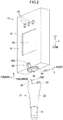
- an up-and-down direction 7 (example of the direction crossing a contact surface) is defined with a direction (pressing direction 82) in which a probe portion 11 is located with respect to a body portion 12 as a downward direction, a forward and backward direction 8 is defined with the side where a display portion 62 is provided as the front, and a left-and-right direction 9 is defined when the blood flow measurement device 10 is viewed from the front.
- the blood flow measurement device 10 measures the blood flow volume by the LDF (abbreviation for Laser Doppler Flowmetry) method.
- the LDP method is a method for calculating the blood flow volume from information based on the Doppler shift of light scattered by erythrocytes when biological tissues are irradiated with laser light.
- the blood flow measurement device 10 has the probe portion 11 (example of the blood flow sensor) and the body portion 12.
- the probe portion 11 is configured so as to be attachable to and detachable from the body portion 12.
- the probe portion 11 has a pair of engagement portions 58 and a protrusion portion 57 (see Fig. 3 ) as described later and the body portion 12 has a pair of engagement portions 65 engaging with the pair of engagement portions 58 of the probe portion 11 and a recessed portion 69 into which the protrusion portion 57 of the probe portion 11 is fitted as described later.
- the probe portion 11 is pulled out from the body portion 12, the upper end portion of the holding portion 22 and the pair of engagement portions 58 are elastically deformed so as to extend outward, and then the protrusion portion 57 and the projections 58A of the engagement portions 58 of the holding portion 22 are separated from the recessed portion 69 and the recessed portions 65A of the engagement portions 65 of the body portion 12, respectively.
- the probe portion 11 is attachable to and detachable from the body portion 12.
- the probe portion 11 has a sensor portion 21, the holding portion 22, a coil spring 23 (example of the transmission portion, the elastic member, and the spring), and a pressure sensor 24.
- the sensor portion 21 has a sensor chip 26 and a sensor housing 27 (example of the housing).
- the sensor chip 26 acquires information on the blood flow volume from a subject in the measurement of the blood flow volume.
- the sensor chip 26 has a laser diode 31 (example of the laser element, hereinafter sometimes also referred to as "LD"), a photodiode 32 (example of the light receiving element, hereinafter sometimes also referred to as "PD”.), and a package 33.
- LD laser diode
- PD photodiode
- PD light receiving element
- the laser diode 31 outputs laser light by a drive current received through a connector 64 described later from the body portion 12.
- the photodiode 32 converts received light into an electrical signal, and then outputs the electrical signal.
- the output electrical signal is transmitted to the body portion 12 through the connector 64.
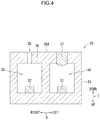
- a package 33 has a substantially rectangular parallelepiped shape with a hollow inside. The inside of the package 33 is divided into two parts. In a LD space 34 of the one part in the package 33, the laser diode 31 is disposed. In a PD space 35 of the other part, the photodiode 32 is disposed.
- a silicon microlens 37 is provided in a portion adjacent to one side of the LD space 34 of an outer wall 36 of the package 33.
- a through-hole 38 is provided in a portion adjacent to one side of the PD space 35 of the outer wall 36.
- Laser light output from the laser diode 31 is output to the outside of the package 33 through the silicon microlens 37.
- the photodiode 32 receives light entering the PD space 35 from the outside of the package 33 through the through-hole 38.
- the sensor chip 26 may have an amplification circuit amplifying the electrical signal output by the photodiode 32.
- the sensor housing 27 holds the sensor chip 26.
- the sensor housing 27 has a substantially cylindrical shape.
- the sensor housing 27 has a through-hole 41.
- the through-hole 41 penetrates the center of a lower wall having a lower surface 27B in the up-and-down direction 7 in the sensor housing 27.
- the sensor chip 26 attached to a substrate 26A for example, is disposed so that a lower surface 36A is directed downward.
- the sensor chip 26 or the substrate 26A is stuck to the sensor housing 27 with an adhesive, for example.
- the sensor housing 27 has a flange 42.
- the flange 42 projects outward from an outer peripheral surface 27A of the sensor housing 27 in an upper portion of the sensor housing 27.
- the sensor housing 27 has a through-hole 43.
- the through-hole 43 penetrates the center of an upper wall 27C of the sensor housing 27 in the up-and-down direction 7.
- An electric cable (not illustrated) electrically connecting the sensor chip 26 and the pressure sensor 24 to a connector 56 described later is inserted into and passed through the through-hole 43.
- the pressure sensor 24 is located on a lower surface 27B of the sensor housing 27.
- the pressure sensor 24 is a piezoelectric element, for example.
- a lower surface 24A of the pressure sensor 24 and the lower surface 36A of the sensor chip 26 are located on the same virtual plane.
- a surface including the lower surface 24A and the lower surface 36A is referred to as "contact surface 44".
- the holding portion 22 holds the sensor housing 27.
- the holding portion 22 has a substantially truncated cone shape.
- the inside of the holding portion 22 is hollow.
- the holding portion 22 has extension portions 51 and 52 and holes 53 and 54.
- the extension portion 51 extends inward from the lower end of the holding portion 22.
- the extension portion 52 extends inward from the vicinity of the center in the up-and-down direction 7 in the internal space of the holding portion 22.
- the hole 53 is a circular hole demarcated by the tip of the extension portion 51 and communicating with space located above and below the extension portion 51.
- the sensor housing 27 is inserted into and passed through the hole 53. When the flange 42 of the sensor housing 27 and the extension portion 51 abut on each other, the sensor housing 27 is prevented from being pulled out downward from the holding portion 22.
- the holding portion 22 has a guide surface 55 formed ranging over the extension portion 51 and the extension portion 52.
- the guide surface 55 is an inner peripheral surface of a cylindrical shape.
- the outer periphery of the flange 42 of the sensor housing 27 is slid with respect to the guide surface 55, whereby the sensor housing 27 is movable in a slide manner in the up-and-down direction 7 with respect to the holding portion 22.
- the hole 54 is a circular hole demarcated by the tip of the extension portion 52 and communicating with space located above and below the extension portion 52.
- the above-described electric cable is inserted into and passed through the hole 54.
- the holding portion 22 is provided with the connector 56.
- the connector 56 is located in a central portion in an upper end portion of the holding portion 22.
- the connector 56 is electrically connected to the sensor chip 26 and the pressure sensor 24 through the above-described electric cable. In a state where the probe portion 11 is attached to the body portion 12, the connector 56 is brought into electrical connection with a connector 64 (see Fig. 2 ) described later.
- the holding portion 22 has the protrusion portion 57.
- the protrusion portion 57 projects inward from the inner peripheral surface in an upper portion of the holding portion 22.
- the protrusion portion 57 is fitted into the recessed portion 69 (see Fig. 2 ) described later, whereby the probe portion 11 is held in the state of being attached to the body portion.
- the holding portion 22 has the pair of engagement portions 58.
- the pair of engagement portions 58 is engaged with the engagement portions 65 of the body portion 12 described later, whereby the probe portion 11 is held in the state of being attached to the body portion 12.
- the pair of engagement portions 58 has a substantially rectangular shape and extends upward from a front portion and a rear portion in the upper end.
- the pair of engagement portions 58 has the projections 58A projecting inward in the forward and backward direction 8 in an upper end portion.
- the coil spring 23 is disposed in a state of being compressed between the upper wall 27C of the sensor housing 27 and the extension portion 52 of the holding portion 22.
- the coil spring 23 absorbs force transmitted from the holding portion 22 to the sensor housing 27. Therefore, even when the holding portion 22 moves in the pressing direction 81 in the state where a subject 82 contacts the contact surface 44, force (hereinafter referred to as "contact pressure") applied to the subject 82 from the contact surface 44 is hard to fluctuate.
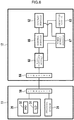
- the body portion 12 calculates the blood flow volume based on the electrical signal relating to the blood flow received from the sensor chip 26, and then displays the blood flow volume on the display portion 62. As illustrated in Fig. 2 , the body portion 12 has a body housing 61, the display portion 62, operation portions 63, and the connector 64.
- the display portion 62 is a liquid crystal panel, for example.
- the display portion 62 receives a signal from a control portion 66 described later, and then displays the blood flow volume as a measurement result, for example.
- the operation portions 63 are buttons, for example.
- the operation portions 63 transmit signals to the control portion 66 in response to the pressing of the buttons by a measurement person.
- the connector 64 is electrically connected to the connector 56 provided in the probe portion 11.
- the body housing 61 has the pair of engagement portions 65.
- the pair of engagement portions 65 is engaged with the engagement portions 58 of the probe portion 11.
- the pair of engagement portions 65 is substantially a rectangular-shaped dent.
- the pair of engagement portions 65 has recessed portions 65A recessed inward in the forward and backward direction 8 in an upper end portion. The projections 58A in the engagement portions 58 of the probe portion 11 are fitted into the recessed portions 65A of the engagement portions 65, whereby the engagement portions 58 and the engagement portions 65 are engaged with each other.
- the body housing 61 has the recessed portion 69 in a lower end portion.
- the recessed portion 69 is an inward recess from the outer peripheral surface of the body housing 61and is formed into an endless annular shape.
- the blood flow measurement device 10 has an attachable and detachable cap 13. In a state of being attached to the blood flow measurement device 10, the cap 13 covers the sensor portion 21.
- the body portion 12 further has the control portion 66 (example of the calculation portion), a power supply portion 67, and a signal processing portion 68.
- the control portion 66 has a CPU (abbreviation for Central Processing Unit) and a memory.
- the memory is, for example, a ROM (abbreviation for Read Only Memory), RAM (abbreviation for Random Access Memory), and EEPROM (abbreviation for Electrically Erasable Programmable Read Onlyl Memory).
- the CPU receives a digital signal based on an electrical signal output from the photodiode 32 of the sensor chip 26 from the signal processing portion 68, and then performs calculation for calculating the blood flow volume. Moreover, the CPU transmits a signal in order to display a measurement result on the display portion 62, and then receives signals output from the operation portions 63 by the operation of the operation portions 63.
- the memory stores programs executed by the CPU and data.
- the power supply portion 67 is a lithium ion battery, for example.
- the power supply portion 67 supplies power to the display portion 62 and the signal processing portion 68 based on a direction from the control portion 66.
- the signal processing portion 68 is a circuit for signal processing and includes an amplification circuit, an A/D (abbreviation for analog/digital) conversion circuit, and a laser drive circuit, for example.
- the signal processing portion 68 outputs a drive current.
- the drive current is transmitted to the laser diode 31 of the sensor chip 26 through the connectors 56 and 64.
- the signal processing portion 68 amplifies an electrical signal received from the photodiode 32 of the sensor chip 26 through the connectors 56 and 64, and converts the same into a digital signal.
- the Laser is emitted to the subject 82 from the laser diode 31 by the drive current output from the signal processing portion 68.
- the photodiode 32 receives reflected light of the light emitted from the laser diode 31, converts the received light into an electrical signal, and then outputs the electrical signal.
- the reflected light received by the photodiode 32 includes scattered light from stationary tissues, such as a blood vessel, and scattered light from moving tissues, such as erythrocytes.
- the scattered light from the moving tissues have a frequency deviated from the frequency of the scattered light from the stationary tissues by the Doppler shift.
- interference occurs in the scattered light from the stationary tissues and the scattered light from the moving tissues and is observed as an optical beat (waviness).
- Information on the frequency of the optical beat is output from the photodiode 32 as an electrical signal.
- the control portion 66 calculates the blood flow volume based on the frequency of the optical beat.
- Measurement processing illustrated in Fig. 7 is processing performed by the control portion 66.
- the measurement processing is performed based on the fact that a power-ON operation of the operation portion 63 has been performed.
- the power-ON operation is an operation that a measurement person depresses a button corresponding to power-ON in the operation portion 63, for example.
- Step S11 it is judged whether the control portion 66 has detected that a power-OFF operation of the operation portion 63 has been performed, i.e., whether the control portion 66 has received a signal corresponding to the power-OFF operation from the operation portion 63 (Step S11).
- the power-off operation is an operation that a measurement person depresses a button corresponding to power-OFF, for example.
- the control portion 66 transmits a power-OFF signal to the power supply portion 67 to thereby stop the supply of the power to the body portion 12 (Step S18) to complete the measurement processing.
- Step S11 When the control portion 66 has not detected that the power-OFF operation of the operation portions 63 has been performed (Step S11: No), the control portion 66 detects the contact pressure applied to the contact surface 44 based on a signal output by the pressure sensor 24 (Step S12). Then, the control portion 66 judges whether the detected contact pressure is larger than 0 (Step S13). It is judged that the contact surface 44 contacts the subject based on the fact that the contact pressure is larger than 0.
- the contact pressure for judging that the contact surface 44 contacts the subject may not necessarily be 0 as a reference and a value close to 0 may be previously set, for example.
- Step S13 When the control portion 66 does not judge that the contact pressure is larger than 0 (Step S13: No), the control portion 66 transmits a laser-off signal to the signal processing portion 68 to thereby cause the signal processing portion 68 to stop the supply of the drive current to the laser diode 31 (Step S14). Then, the control portion 66 judges whether 1 is stored in a time flag stored in the memory (Step S15).
- Step S15: No When the control portion 66 judges that 1 is not stored in the time flag (Step S15: No), the control portion 66 starts timing and stores 1 in the time flag stored in the memory (Step S16) to proceed the process to Step S17.
- Step S16 When the control portion 66 judges that 1 is stored in the time flag (Step S15: Yes), the control portion 66 skips the processing of Step S16, and then proceeds the process to Step S17.
- Step S17 the control portion 66 judges whether a predetermined time stored in the memory, for example, 120 seconds, has passed after starting the timing.
- a predetermined time stored in the memory for example, 120 seconds
- the control portion 66 transmits a power-OFF signal to the power supply portion 67 to thereby stop the supply of the power to the body portion 12 (Step S18) to complete the measurement processing.
- Step S17 when the control portion 66 does not judge that 120 seconds have passed after starting the timing (Step S17: No), the control portion 66 returns the process to the processing of Step S11, and then judges whether a power-OFF operation of the operation portions 63 has been performed based on signals input from the operation portions 63.
- Step S13 When the control portion 66 has judged that the contact pressure is larger than 0 (Step S13: Yes), the control portion 66 transmits a laser-on signal to the signal processing portion 68 to thereby cause the signal processing portion 68 to start the supply of a drive current to the laser diode 31 (Step S19) .
- control portion 66 stops the timing and stores 0 in the time flag stored in the memory (Step S20). When timing is not performed and 0 is stored in the time flag, the control portion 66 may not perform this step.
- Step S21 the control portion 66 judges whether the contact pressure detected in Step S12 is within a predetermined specified pressure range previously stored in the memory (Step S21).
- the specified pressure range is previously set as the range of the contact pressure where the blood flow measurement is stably performed.
- Step S21: Yes the control portion 66 acquires a digital signal output from the signal processing portion 68 (Step S22).
- Step S23 the control portion 66 calculates the blood flow volume based on the acquired digital signal
- Step S24 stores the calculated blood flow volume in the memory
- Step S22, the processing of Step S23, and the processing of Step S24 are performed at predetermined time intervals previously stored in the memory, for example, 5 seconds.
- a plurality of blood flow volumes with time intervals is acquired.
- the blood flow volume to be stored is added and stored without overwriting the previously stored blood flow volume. Therefore, when the measurement is continued, the plurality of blood flow volumes is stored in the memory.
- the number of the blood flow volumes stored in the memory may be counted by counting up a counter whenever the blood flow volume is stored in the memory.
- the control portion 66 judges whether the predetermined number, e.g., five or more, of blood flow volumes previously stored in the memory are stored in the memory (Step S25).
- the control portion 66 judges that the predetermined number or more of the blood flow volumes are stored in the memory (Step S25: Yes)
- the control portion 66 calculates an average value of the blood flow volumes stored in the memory (Step S26) .
- the control portion 66 displays the calculated average value as a measurement result of blood flow volume on the display portion 62 (Step S27).
- Step S21 No
- the control portion 66 judges whether the control portion 66 has detected that a power-OFF operation of the operation portions 63 has been performed based on signals input from the operation portions 63.
- the blood flow volume is measured in the state where the contact surface 44 of the sensor housing 27 is brought into contact with the subject 82 (for example, skin of a human body).
- the sensor housing 27 is movably held in the holding portion 22.
- External force for example, force applied to the blood flow measurement device 10 by a measurement person
- the holding portion 22 is absorbed and transmitted to the sensor housing 27 by the coil spring 23. Therefore, when the external force is applied to the holding portion 22, changes of the contact pressure of the contact surface 44 to the subject 82 (skin) are suppressed.
- a fluctuation of the blood flow volume of the subject 82 during the measurement is suppressed.
- the control portion 66 stops the calculation of calculating the blood flow volume according to the fact that the contact pressure detected by the pressure sensor 24 is not within the predetermined range, and therefore the display of measurement results with low reliability on the display portion 62 is avoided.
- the control portion 66 starts the calculation of calculating the blood flow volume according to the fact that the pressure has been detected by the pressure sensor 24, and therefore even when the pressure detected by the pressure sensor 24 is out of the predetermined range, the calculation is resumed without explicit giving of a direction of starting the measurement to the control portion 66 by a measurement person.
- the control portion 66 performs the calculation of calculating the blood flow volume by a plurality of times, and then calculates an average value of results of the plurality of times of the calculations. Then, the average value is displayed as a measurement result on the display portion 62. Therefore, a more reliable measurement result is displayed.
- a probe portion 15 (example of the blood flow sensor) is used in place of the probe portion 11 in the blood flow measurement device 10 of the first embodiment.
- the other configurations are the same as those of the first embodiment.
- the probe portion 15 is attachable to and detachable from the body portion 12 as with the probe portion 11.
- the probe portion 15 has an optical sensor portion 71, a holding portion 72, a moving member 73, a pressure sensor 74, and coil springs 75 and 76.
- the optical sensor portion 71 has a sensor chip 83 and a sensor housing 84 (example of the housing) similar to the sensor portion 21 according to the first embodiment, and therefore a detailed explanation is omitted herein.
- the optical sensor portion 71 is not provided with a pressure sensor.
- the holding portion 72 holds the optical sensor portion 71 so as to be movable in the up-and-down direction 7.
- the outer shape of the holding portion 72 is a substantially truncated cone shape.
- the inside of the holding portion 72 is space where a part of the optical sensor portion 71 and the moving member 73, the pressure sensor 74, and the coil springs 75 and 76 can be accommodated.
- an opening 85 is formed in the lower end of the outer wall forming the outer shape of the holding portion 72.
- the inner diameter of the opening 85 is equivalent to the outer diameter in the vicinity of the center in the up-and-down direction 7 of the sensor housing 84.
- the opening 85 is opened along the up-and-down direction 7.
- the optical sensor portion 71 is inserted into the opening 85.
- a flange 84A extending outward is formed in the upper end of the sensor housing 84.
- the outer shape of the flange 84A is larger than the inner diameter of the opening 85.
- the flange 84A can abut on a peripheral portion 86 demarcating the opening 85 from above. Due to the fact that the flange 84A abuts on the peripheral portion 86, the moving lower end (position illustrated in Fig. 8 ) of the optical sensor portion 71 moving in the up-and-down direction 7 with respect to the opening 85 is determined.
- an inner peripheral surface 87 of a cylindrical shape extends upward from the peripheral portion 86.
- the inner diameter of the inner peripheral surface 87 is constant in the up-and-down direction 7 and is equivalent to the outer shape of the peripheral portion 86.
- a guide tube 88 In the vicinity of an upper portion of the inner peripheral surface 87, a guide tube 88 is formed.
- the guide tube 88 has a cylindrical shape with an outer diameter smaller than the inner diameter of the inner peripheral surface 87.
- An upper wall 90 expanding outward is formed on the upper end of the guide tube 88.
- the upper wall 90 is continuous to the outer wall of the holding portion 72.
- the upper end of the guide tube 88 is blocked with the upper wall 90.
- an opening 91 is formed in the lower end of the guide tube 88.
- the inner peripheral surface 92 of the guide tube 88 guides the moving member 73 in the up-and-down direction 7.
- the moving member 73 has a disk portion 94, a first projection 95 projecting upward from the disk portion 94, and a second projection 96 projecting downward from the disk portion 94.
- the disk portion 94 has a disk shape with an outer diameter equivalent to the inner diameter of the inner peripheral surface 92 of the guide tube 88.
- the disk portion 94 is accommodated in the internal space of the guide tube 88 with an attitude that flat upper and lower surfaces are individually directed in the up-and-down direction 7 and is movable in the up-and-down direction 7 while the outer peripheral surface is sliding on the inner peripheral surface 92.
- the first projection 95 projects upward from the center of the disk portion 94.
- the length of the first projection 95 projecting upward from the disk portion 94 is shorter than the length along the up-and-down direction 7 of the guide tube 88.
- the second projection 96 projects downward from the center of the disk portion 94.
- the length of the second projection 96 projecting downward from the disk portion 94 is shorter than the length along the up-and-down direction 7 from the upper wall 90 of the guide tube 88 to the peripheral portion 86.
- the length along the up-and-down direction 7 of the moving member 73 is longer than the length along the up-and-down direction 7 of the guide tube 88.
- the second projection 96 can abut on a recessed portion 80 formed in the center of the upper wall 89 of the sensor housing 84 of the optical sensor portion 71.
- a pressure sensor 74 is provided on the lower surface of the upper wall 90 of the guide tube 88.
- the pressure sensor 74 is a pressure sensitive sensor, such as a piezoelectric element, for example.
- the lower surface is a pressure sensitive surface and outputs an electrical signal according to the magnitude of the force given to the lower surface.
- the first projection 95 of the moving member 73 can abut.
- the coil spring 75 (example of the first elastic body) is located between the moving member 73 and the pressure sensor 74 with the disk portion 94 of the moving member 73 and the upper wall 90 of the guide tube 88 as spring seats.
- the moving member 73 is energized downward (example of the first direction) in Fig. 8 by the coil spring 75.
- the coil spring 75 can be elastically compressed and deformed in the up-and-down direction 7. Due to the fact that the moving member 73 moves upward (example of the second direction) in Fig. 8 against the energization force of the coil spring 75, the first projection 95 of the moving member 73 abuts on the pressure sensor 74 (see Fig. 9 ).
- the coil spring 76 (example of the second elastic body) is located between the disk portion 94 of the moving member 73 and a spring seat 93 which is formed on the upper surface of the sensor housing 84 of the optical sensor portion 71 and is recessed downward.
- the optical sensor portion 71 is energized downward in Fig. 8 by the coil springs 75 and 76.
- the coil spring 76 can be elastically compressed and deformed in the up-and-down direction 7. Due to the fact that the optical sensor portion 71 moves upward in Fig. 8 against the energization force of the coil spring 76, the second projection 96 of the moving member 73 abuts on the recessed portion 80 of the optical sensor portion 71 (see Fig. 10 ).
- First energization force F1 of the coil spring 75 in a state where the first projection 95 of the moving member 73 and the pressure sensor 74 abut on each other is lower than second energization force F2 of the coil spring 76 in a state where the second projection 96 of the moving member 73 and the recessed portion 80 of the optical sensor portion 71 abut on each other (see Fig. 10 ) (F1 ⁇ F2). Therefore, the coil spring 75 is more easily compressed and deformed than the coil spring 76.
- a first distance L1 along the up-and-down direction 7 (movement direction) between the upper end of the first projection 95 of the moving member 73 and the pressure sensor 74 is shorter than a second distance L2 along the up-and-down direction 7 between the recessed portion 80 of the optical sensor portion 71 and the lower end of the second projection 96 of the moving member 73 (L1 ⁇ L2).
- a connector 77 is provided in the vicinity of the upper end of the holding portion 72.
- the connector 77 is electrically connected to the sensor chip 83 and the pressure sensor 74 through an electric cable.
- the connector 77 is electrically connected to the connector 64 (see Fig. 2 ).
- a protrusion portion 97 projecting inwardly is formed in the vicinity of the upper end of the inner peripheral surface of the holding portion 72.
- the protrusion portion 97 is fitted into the recessed portion 69 (see Fig. 2 ), whereby the probe portion 15 is attached to the body portion 12.
- Measurement processing using the probe portion 15 is performed by the control portion 66 (example of the calculation portion).
- a memory (example of the storage portion) of the calculation portion 66, a first threshold value and a second threshold value are previously stored.
- the first threshold value is a value which is expected to be output from the pressure sensor 74 when the coil spring 75 is compressed and deformed, so that the first projection 95 of the moving member 73 abuts on the pressure sensor 74.
- the second threshold value is a value which is expected to be output from the pressure sensor 74 when the coil springs 75 and 76 are compressed and deformed, so that the first projection 95 of the moving member 73 abuts on the pressure sensor 74 and the second projection 96 of the moving member 73 abuts on the recessed portion 80 of the optical sensor portion 71.
- the measurement processing using the probe portion 15 is the same as the measurement processing in the first embodiment. More specifically, when the control portion 66 does not detect that a power-OFF operation of the operation portions 63 has been performed ( Fig. 7 , step S11: No), the control portion 66 calculates pressure based on a signal output by the pressure sensor 74 ( Fig. 7 , Step S12) . Then, the control portion 66 judges whether the calculated pressure is higher than the first threshold value ( Fig. 7 , Step S13). It is judged that the optical sensor portion 71 contacts the subject based on the fact that the contact pressure is higher than the first threshold value. The electric strength of signals, such as a voltage, may be compared with the first threshold value without calculating pressure based on a signal output by the pressure sensor 74.
- control portion 66 judges whether the pressure detected in Step S12 is within a predetermined specified pressure range, i.e., between the first threshold value and the second threshold value, previously stored in the memory ( Fig. 7 , Step S21). In a case where the control portion 66 has judged that the pressure detected in Step S12 is not within the specified pressure range in Step S21 ( Fig. 7 , Step S21: No), when the blood flow volume is already stored in the memory in Step S24, the control portion 66 erases the blood flow volume from the memory, and then returns the process to the processing of Step S11. Moreover, the control portion 66 displays a display warning that the pressure applied to the optical sensor portion 71 is out of the fixed range on the display portion 62 (example of the warning portion).
- the moving member 73 moves upward, so that the first projection 95 abuts on the pressure sensor 74.
- the calculation portion 66 receives a signal output from the pressure sensor 74 by the abutment of the first projection 95, and then calculates the blood flow volume based on the output of the optical sensor portion 71.
- the coil spring 75 When the contact surface of the optical sensor portion 71 is brought into contact with a subject in the state where the holding portion 72 is directly or indirectly held by a user, the coil spring 75 is compressed and deformed, so that the first projection 95 and the pressure sensor 74 abut on each other. Furthermore, when the contact surface of the optical sensor portion 71 is strongly pressed against a subject, the coil spring 76 is compressed and deformed, so that the recessed portion 80 and the second projection 96 abut on each other. Thus, the force applied to the optical sensor portion 71 is directly transmitted to the pressure sensor 74 without being absorbed by the coil springs 75 and 76.
- the first projection 95 of the moving member 73 and the pressure sensor 74 abut on each other with a relatively short distance. Moreover, the distance until the recessed portion 80 of the optical sensor portion 71 and the second projection 96 of the moving member 73 abut on each other in the state where the first projection 95 and the pressure sensor 74 abut on each other is relatively long, and therefore a relative distance between the recessed portion 80 of the optical sensor portion 71 and the second projection 96 of the moving member 73 where the blood flow volume can be measured is long.
- the calculation portion 66 calculates the blood flow volume.
- a warning is issued.
- the coil springs 23, 75, and 76 are used as examples of the transmission portion, the other members may be used in place of the coil springs 23, 75, and 76 insofar as the members can absorb and transmit external force applied to the holding portions 22 and 72 to the sensor housings 27 and 84.
- elastic bodies such as a sponge, a porous elastic body, and a gel elastic body, dampers containing air or liquid thereinside, and dampers using repulsive force, such as electromagnetic force, may be used in places of the coil springs 23, 75, and 76.
- the contact surface 44 does not necessarily need to be a plane and the contact surface 44 may be a projected curved surface, for example.
- the power supply portion 67 does not necessarily need to be a lithium ion battery and may be another secondary battery or may be a primary battery. Moreover, a commercial power supply may be used.
- the blood flow measurement device 10 may be provided with a sending portion capable of sending data to information processing devices, such as a PC (abbreviation for a personal computer).
- a PC abbreviation for a personal computer
- the warning that the pressure applied to the optical sensor portion 71 is out of the specified range may be issued with a buzzer sound, an LED lamp, or the like, for example, in place of the display by the display portion 62.
Landscapes
- Health & Medical Sciences (AREA)
- Life Sciences & Earth Sciences (AREA)
- Engineering & Computer Science (AREA)
- Medical Informatics (AREA)
- Physics & Mathematics (AREA)
- Veterinary Medicine (AREA)
- Biophysics (AREA)
- Pathology (AREA)
- Public Health (AREA)
- Biomedical Technology (AREA)
- Heart & Thoracic Surgery (AREA)
- General Health & Medical Sciences (AREA)
- Molecular Biology (AREA)
- Surgery (AREA)
- Animal Behavior & Ethology (AREA)
- Hematology (AREA)
- Physiology (AREA)
- Cardiology (AREA)
- Measuring Pulse, Heart Rate, Blood Pressure Or Blood Flow (AREA)
Priority Applications (1)
| Application Number | Priority Date | Filing Date | Title |
|---|---|---|---|
| EP20169625.9A EP3698706B1 (de) | 2016-03-04 | 2017-03-03 | Blutflusssensor und blutflussmessvorrichtung |
Applications Claiming Priority (2)
| Application Number | Priority Date | Filing Date | Title |
|---|---|---|---|
| JP2016041704 | 2016-03-04 | ||
| PCT/JP2017/008499 WO2017150708A1 (ja) | 2016-03-04 | 2017-03-03 | 血流センサ及び血流測定装置 |
Related Child Applications (2)
| Application Number | Title | Priority Date | Filing Date |
|---|---|---|---|
| EP20169625.9A Division EP3698706B1 (de) | 2016-03-04 | 2017-03-03 | Blutflusssensor und blutflussmessvorrichtung |
| EP20169625.9A Division-Into EP3698706B1 (de) | 2016-03-04 | 2017-03-03 | Blutflusssensor und blutflussmessvorrichtung |
Publications (3)
| Publication Number | Publication Date |
|---|---|
| EP3424417A1 true EP3424417A1 (de) | 2019-01-09 |
| EP3424417A4 EP3424417A4 (de) | 2019-10-30 |
| EP3424417B1 EP3424417B1 (de) | 2022-08-17 |
Family
ID=59743000
Family Applications (2)
| Application Number | Title | Priority Date | Filing Date |
|---|---|---|---|
| EP20169625.9A Active EP3698706B1 (de) | 2016-03-04 | 2017-03-03 | Blutflusssensor und blutflussmessvorrichtung |
| EP17760170.5A Active EP3424417B1 (de) | 2016-03-04 | 2017-03-03 | Blutflusssensor und blutflussmessvorrichtung |
Family Applications Before (1)
| Application Number | Title | Priority Date | Filing Date |
|---|---|---|---|
| EP20169625.9A Active EP3698706B1 (de) | 2016-03-04 | 2017-03-03 | Blutflusssensor und blutflussmessvorrichtung |
Country Status (5)
| Country | Link |
|---|---|
| US (1) | US11202581B2 (de) |
| EP (2) | EP3698706B1 (de) |
| JP (1) | JP6881774B2 (de) |
| CN (1) | CN109069042B (de) |
| WO (1) | WO2017150708A1 (de) |
Cited By (2)
| Publication number | Priority date | Publication date | Assignee | Title |
|---|---|---|---|---|
| WO2021180947A1 (en) * | 2020-03-12 | 2021-09-16 | Smith & Nephew Plc | Device, apparatus and method of determining skin perfusion pressure |
| US11944418B2 (en) | 2018-09-12 | 2024-04-02 | Smith & Nephew Plc | Device, apparatus and method of determining skin perfusion pressure |
Families Citing this family (3)
| Publication number | Priority date | Publication date | Assignee | Title |
|---|---|---|---|---|
| CN111248863B (zh) * | 2020-01-19 | 2023-01-31 | 国家康复辅具研究中心 | 一种诱发人体皮肤充血响应的加压装置 |
| WO2023181824A1 (ja) * | 2022-03-22 | 2023-09-28 | テルモ株式会社 | 心音取得装置、心音取得システム、心音取得方法、及びプログラム |
| WO2023238853A1 (ja) * | 2022-06-07 | 2023-12-14 | マルホ株式会社 | 肌性状測定装置 |
Family Cites Families (10)
| Publication number | Priority date | Publication date | Assignee | Title |
|---|---|---|---|---|
| JPS5323182A (en) * | 1976-08-14 | 1978-03-03 | Michishi Tani | Device for diagnosing pulsation |
| JPS5459786U (de) | 1977-10-04 | 1979-04-25 | ||
| GB2132483B (en) * | 1982-04-07 | 1986-02-12 | Univ Manchester | A device for measuring blood flow |
| JPS6397146A (ja) | 1986-10-14 | 1988-04-27 | キヤノン株式会社 | 血流計測用プロ−ブ |
| JP3243970B2 (ja) * | 1995-05-12 | 2002-01-07 | セイコーエプソン株式会社 | 健康状態解析装置 |
| JP3672393B2 (ja) | 1996-10-21 | 2005-07-20 | オメガウェーブ株式会社 | レーザー血流計の光ファイバープローブ |
| JP2007244600A (ja) | 2006-03-15 | 2007-09-27 | Fujitsu Ltd | 脈波検出方法及び装置 |
| US8805464B2 (en) * | 2007-03-20 | 2014-08-12 | Pioneer Corporation | Bio-information measuring apparatus |
| JP4948326B2 (ja) | 2007-08-21 | 2012-06-06 | 株式会社日立製作所 | 生体光計測用頭部装着式ホルダ |
| EP3076859A4 (de) | 2013-12-05 | 2017-08-09 | Veriskin, Inc. | Hautperfusions-überwachungsvorrichtung |
-
2017
- 2017-03-03 US US16/080,052 patent/US11202581B2/en active Active
- 2017-03-03 JP JP2018503420A patent/JP6881774B2/ja active Active
- 2017-03-03 CN CN201780014900.3A patent/CN109069042B/zh active Active
- 2017-03-03 EP EP20169625.9A patent/EP3698706B1/de active Active
- 2017-03-03 EP EP17760170.5A patent/EP3424417B1/de active Active
- 2017-03-03 WO PCT/JP2017/008499 patent/WO2017150708A1/ja active Application Filing
Cited By (2)
| Publication number | Priority date | Publication date | Assignee | Title |
|---|---|---|---|---|
| US11944418B2 (en) | 2018-09-12 | 2024-04-02 | Smith & Nephew Plc | Device, apparatus and method of determining skin perfusion pressure |
| WO2021180947A1 (en) * | 2020-03-12 | 2021-09-16 | Smith & Nephew Plc | Device, apparatus and method of determining skin perfusion pressure |
Also Published As
| Publication number | Publication date |
|---|---|
| CN109069042B (zh) | 2021-11-02 |
| EP3698706A1 (de) | 2020-08-26 |
| CN109069042A (zh) | 2018-12-21 |
| EP3698706B1 (de) | 2021-09-08 |
| US20190014995A1 (en) | 2019-01-17 |
| US11202581B2 (en) | 2021-12-21 |
| WO2017150708A1 (ja) | 2017-09-08 |
| EP3424417A4 (de) | 2019-10-30 |
| JP6881774B2 (ja) | 2021-06-02 |
| EP3424417B1 (de) | 2022-08-17 |
| JPWO2017150708A1 (ja) | 2018-12-27 |
Similar Documents
| Publication | Publication Date | Title |
|---|---|---|
| EP3698706B1 (de) | Blutflusssensor und blutflussmessvorrichtung | |
| JP4485234B2 (ja) | 生体情報計測装置 | |
| JP2005270544A (ja) | 生体情報計測装置 | |
| US7060963B2 (en) | Organism information measuring device and organism information measuring method | |
| US10641695B2 (en) | Method of determining operation conditions of a laser-based particle detector | |
| JP5565463B2 (ja) | 脈波センサ装置 | |
| JPWO2014024626A1 (ja) | 生体情報測定装置、およびパルスオキシメータ | |
| KR102560304B1 (ko) | 전자 장치, 전자 장치의 혈압 측정 방법, 및 혈압 측정 시스템 | |
| JP2013007744A5 (de) | ||
| WO2015046429A1 (ja) | 脈波検出装置 | |
| JPWO2019054113A1 (ja) | 挿入装置及び検出装置 | |
| US20190261865A1 (en) | Blood pressure measurement device and blood pressure measurement method | |
| JP2017153616A (ja) | パルスオキシメータプローブ | |
| KR20220030089A (ko) | 생체정보 추정 장치 및 방법 | |
| WO2018096864A1 (ja) | 携帯型測定器 | |
| US10238297B2 (en) | Object information acquiring apparatus | |
| JP2017093808A (ja) | 携帯型生体情報測定装置 | |
| JP4476665B2 (ja) | 生体情報計測装置 | |
| JP6437893B2 (ja) | 脈波計 | |
| US20170172416A1 (en) | Biological information acquisition apparatus and biological information acquisition method | |
| JP7058376B1 (ja) | 測定装置、および推定システム | |
| JP2019033902A (ja) | 生体解析装置、生体解析方法およびプログラム | |
| EP2887059A1 (de) | Fotoakustischer wellenmesser | |
| JP2015029760A (ja) | 情報検出器及び情報検出方法 | |
| JP2018061665A (ja) | 光照射装置 |
Legal Events
| Date | Code | Title | Description |
|---|---|---|---|
| STAA | Information on the status of an ep patent application or granted ep patent |
Free format text: STATUS: THE INTERNATIONAL PUBLICATION HAS BEEN MADE |
|
| PUAI | Public reference made under article 153(3) epc to a published international application that has entered the european phase |
Free format text: ORIGINAL CODE: 0009012 |
|
| STAA | Information on the status of an ep patent application or granted ep patent |
Free format text: STATUS: REQUEST FOR EXAMINATION WAS MADE |
|
| 17P | Request for examination filed |
Effective date: 20181001 |
|
| AK | Designated contracting states |
Kind code of ref document: A1 Designated state(s): AL AT BE BG CH CY CZ DE DK EE ES FI FR GB GR HR HU IE IS IT LI LT LU LV MC MK MT NL NO PL PT RO RS SE SI SK SM TR |
|
| AX | Request for extension of the european patent |
Extension state: BA ME |
|
| STAA | Information on the status of an ep patent application or granted ep patent |
Free format text: STATUS: REQUEST FOR EXAMINATION WAS MADE |
|
| DAV | Request for validation of the european patent (deleted) | ||
| DAX | Request for extension of the european patent (deleted) | ||
| A4 | Supplementary search report drawn up and despatched |
Effective date: 20191002 |
|
| RIC1 | Information provided on ipc code assigned before grant |
Ipc: A61B 5/026 20060101ALI20190926BHEP Ipc: A61B 5/0285 20060101AFI20190926BHEP |
|
| GRAP | Despatch of communication of intention to grant a patent |
Free format text: ORIGINAL CODE: EPIDOSNIGR1 |
|
| STAA | Information on the status of an ep patent application or granted ep patent |
Free format text: STATUS: GRANT OF PATENT IS INTENDED |
|
| INTG | Intention to grant announced |
Effective date: 20220414 |
|
| GRAS | Grant fee paid |
Free format text: ORIGINAL CODE: EPIDOSNIGR3 |
|
| GRAA | (expected) grant |
Free format text: ORIGINAL CODE: 0009210 |
|
| STAA | Information on the status of an ep patent application or granted ep patent |
Free format text: STATUS: THE PATENT HAS BEEN GRANTED |
|
| AK | Designated contracting states |
Kind code of ref document: B1 Designated state(s): AL AT BE BG CH CY CZ DE DK EE ES FI FR GB GR HR HU IE IS IT LI LT LU LV MC MK MT NL NO PL PT RO RS SE SI SK SM TR |
|
| REG | Reference to a national code |
Ref country code: CH Ref legal event code: EP |
|
| REG | Reference to a national code |
Ref country code: DE Ref legal event code: R096 Ref document number: 602017060765 Country of ref document: DE |
|
| REG | Reference to a national code |
Ref country code: IE Ref legal event code: FG4D |
|
| REG | Reference to a national code |
Ref country code: AT Ref legal event code: REF Ref document number: 1511631 Country of ref document: AT Kind code of ref document: T Effective date: 20220915 |
|
| REG | Reference to a national code |
Ref country code: NL Ref legal event code: MP Effective date: 20220817 |
|
| REG | Reference to a national code |
Ref country code: LT Ref legal event code: MG9D |
|
| PG25 | Lapsed in a contracting state [announced via postgrant information from national office to epo] |
Ref country code: SE Free format text: LAPSE BECAUSE OF FAILURE TO SUBMIT A TRANSLATION OF THE DESCRIPTION OR TO PAY THE FEE WITHIN THE PRESCRIBED TIME-LIMIT Effective date: 20220817 Ref country code: RS Free format text: LAPSE BECAUSE OF FAILURE TO SUBMIT A TRANSLATION OF THE DESCRIPTION OR TO PAY THE FEE WITHIN THE PRESCRIBED TIME-LIMIT Effective date: 20220817 Ref country code: PT Free format text: LAPSE BECAUSE OF FAILURE TO SUBMIT A TRANSLATION OF THE DESCRIPTION OR TO PAY THE FEE WITHIN THE PRESCRIBED TIME-LIMIT Effective date: 20221219 Ref country code: NO Free format text: LAPSE BECAUSE OF FAILURE TO SUBMIT A TRANSLATION OF THE DESCRIPTION OR TO PAY THE FEE WITHIN THE PRESCRIBED TIME-LIMIT Effective date: 20221117 Ref country code: NL Free format text: LAPSE BECAUSE OF FAILURE TO SUBMIT A TRANSLATION OF THE DESCRIPTION OR TO PAY THE FEE WITHIN THE PRESCRIBED TIME-LIMIT Effective date: 20220817 Ref country code: LV Free format text: LAPSE BECAUSE OF FAILURE TO SUBMIT A TRANSLATION OF THE DESCRIPTION OR TO PAY THE FEE WITHIN THE PRESCRIBED TIME-LIMIT Effective date: 20220817 Ref country code: LT Free format text: LAPSE BECAUSE OF FAILURE TO SUBMIT A TRANSLATION OF THE DESCRIPTION OR TO PAY THE FEE WITHIN THE PRESCRIBED TIME-LIMIT Effective date: 20220817 Ref country code: FI Free format text: LAPSE BECAUSE OF FAILURE TO SUBMIT A TRANSLATION OF THE DESCRIPTION OR TO PAY THE FEE WITHIN THE PRESCRIBED TIME-LIMIT Effective date: 20220817 |
|
| REG | Reference to a national code |
Ref country code: AT Ref legal event code: MK05 Ref document number: 1511631 Country of ref document: AT Kind code of ref document: T Effective date: 20220817 |
|
| PG25 | Lapsed in a contracting state [announced via postgrant information from national office to epo] |
Ref country code: PL Free format text: LAPSE BECAUSE OF FAILURE TO SUBMIT A TRANSLATION OF THE DESCRIPTION OR TO PAY THE FEE WITHIN THE PRESCRIBED TIME-LIMIT Effective date: 20220817 Ref country code: IS Free format text: LAPSE BECAUSE OF FAILURE TO SUBMIT A TRANSLATION OF THE DESCRIPTION OR TO PAY THE FEE WITHIN THE PRESCRIBED TIME-LIMIT Effective date: 20221217 Ref country code: HR Free format text: LAPSE BECAUSE OF FAILURE TO SUBMIT A TRANSLATION OF THE DESCRIPTION OR TO PAY THE FEE WITHIN THE PRESCRIBED TIME-LIMIT Effective date: 20220817 Ref country code: GR Free format text: LAPSE BECAUSE OF FAILURE TO SUBMIT A TRANSLATION OF THE DESCRIPTION OR TO PAY THE FEE WITHIN THE PRESCRIBED TIME-LIMIT Effective date: 20221118 |
|
| PG25 | Lapsed in a contracting state [announced via postgrant information from national office to epo] |
Ref country code: SM Free format text: LAPSE BECAUSE OF FAILURE TO SUBMIT A TRANSLATION OF THE DESCRIPTION OR TO PAY THE FEE WITHIN THE PRESCRIBED TIME-LIMIT Effective date: 20220817 Ref country code: RO Free format text: LAPSE BECAUSE OF FAILURE TO SUBMIT A TRANSLATION OF THE DESCRIPTION OR TO PAY THE FEE WITHIN THE PRESCRIBED TIME-LIMIT Effective date: 20220817 Ref country code: ES Free format text: LAPSE BECAUSE OF FAILURE TO SUBMIT A TRANSLATION OF THE DESCRIPTION OR TO PAY THE FEE WITHIN THE PRESCRIBED TIME-LIMIT Effective date: 20220817 Ref country code: DK Free format text: LAPSE BECAUSE OF FAILURE TO SUBMIT A TRANSLATION OF THE DESCRIPTION OR TO PAY THE FEE WITHIN THE PRESCRIBED TIME-LIMIT Effective date: 20220817 Ref country code: CZ Free format text: LAPSE BECAUSE OF FAILURE TO SUBMIT A TRANSLATION OF THE DESCRIPTION OR TO PAY THE FEE WITHIN THE PRESCRIBED TIME-LIMIT Effective date: 20220817 Ref country code: AT Free format text: LAPSE BECAUSE OF FAILURE TO SUBMIT A TRANSLATION OF THE DESCRIPTION OR TO PAY THE FEE WITHIN THE PRESCRIBED TIME-LIMIT Effective date: 20220817 |
|
| PGFP | Annual fee paid to national office [announced via postgrant information from national office to epo] |
Ref country code: FR Payment date: 20230320 Year of fee payment: 7 |
|
| REG | Reference to a national code |
Ref country code: DE Ref legal event code: R097 Ref document number: 602017060765 Country of ref document: DE |
|
| PG25 | Lapsed in a contracting state [announced via postgrant information from national office to epo] |
Ref country code: SK Free format text: LAPSE BECAUSE OF FAILURE TO SUBMIT A TRANSLATION OF THE DESCRIPTION OR TO PAY THE FEE WITHIN THE PRESCRIBED TIME-LIMIT Effective date: 20220817 Ref country code: EE Free format text: LAPSE BECAUSE OF FAILURE TO SUBMIT A TRANSLATION OF THE DESCRIPTION OR TO PAY THE FEE WITHIN THE PRESCRIBED TIME-LIMIT Effective date: 20220817 |
|
| PGFP | Annual fee paid to national office [announced via postgrant information from national office to epo] |
Ref country code: BE Payment date: 20230321 Year of fee payment: 7 |
|
| PLBE | No opposition filed within time limit |
Free format text: ORIGINAL CODE: 0009261 |
|
| STAA | Information on the status of an ep patent application or granted ep patent |
Free format text: STATUS: NO OPPOSITION FILED WITHIN TIME LIMIT |
|
| PG25 | Lapsed in a contracting state [announced via postgrant information from national office to epo] |
Ref country code: AL Free format text: LAPSE BECAUSE OF FAILURE TO SUBMIT A TRANSLATION OF THE DESCRIPTION OR TO PAY THE FEE WITHIN THE PRESCRIBED TIME-LIMIT Effective date: 20220817 |
|
| 26N | No opposition filed |
Effective date: 20230519 |
|
| PG25 | Lapsed in a contracting state [announced via postgrant information from national office to epo] |
Ref country code: SI Free format text: LAPSE BECAUSE OF FAILURE TO SUBMIT A TRANSLATION OF THE DESCRIPTION OR TO PAY THE FEE WITHIN THE PRESCRIBED TIME-LIMIT Effective date: 20220817 |
|
| PG25 | Lapsed in a contracting state [announced via postgrant information from national office to epo] |
Ref country code: MC Free format text: LAPSE BECAUSE OF FAILURE TO SUBMIT A TRANSLATION OF THE DESCRIPTION OR TO PAY THE FEE WITHIN THE PRESCRIBED TIME-LIMIT Effective date: 20220817 |
|
| REG | Reference to a national code |
Ref country code: CH Ref legal event code: PL |
|
| PG25 | Lapsed in a contracting state [announced via postgrant information from national office to epo] |
Ref country code: LU Free format text: LAPSE BECAUSE OF NON-PAYMENT OF DUE FEES Effective date: 20230303 |
|
| REG | Reference to a national code |
Ref country code: IE Ref legal event code: MM4A |
|
| PG25 | Lapsed in a contracting state [announced via postgrant information from national office to epo] |
Ref country code: LI Free format text: LAPSE BECAUSE OF NON-PAYMENT OF DUE FEES Effective date: 20230331 Ref country code: IE Free format text: LAPSE BECAUSE OF NON-PAYMENT OF DUE FEES Effective date: 20230303 Ref country code: CH Free format text: LAPSE BECAUSE OF NON-PAYMENT OF DUE FEES Effective date: 20230331 |
|
| PGFP | Annual fee paid to national office [announced via postgrant information from national office to epo] |
Ref country code: DE Payment date: 20240301 Year of fee payment: 8 Ref country code: GB Payment date: 20240322 Year of fee payment: 8 |