EP3424290B1 - Verteilgerät für streugut - Google Patents
Verteilgerät für streugut Download PDFInfo
- Publication number
- EP3424290B1 EP3424290B1 EP18401055.1A EP18401055A EP3424290B1 EP 3424290 B1 EP3424290 B1 EP 3424290B1 EP 18401055 A EP18401055 A EP 18401055A EP 3424290 B1 EP3424290 B1 EP 3424290B1
- Authority
- EP
- European Patent Office
- Prior art keywords
- drive shaft
- guide elements
- distributor
- actuating member
- centrifugal disc
- Prior art date
- Legal status (The legal status is an assumption and is not a legal conclusion. Google has not performed a legal analysis and makes no representation as to the accuracy of the status listed.)
- Active
Links
Images


Classifications
-
- A—HUMAN NECESSITIES
- A01—AGRICULTURE; FORESTRY; ANIMAL HUSBANDRY; HUNTING; TRAPPING; FISHING
- A01C—PLANTING; SOWING; FERTILISING
- A01C17/00—Fertilisers or seeders with centrifugal wheels
- A01C17/006—Regulating or dosing devices
- A01C17/008—Devices controlling the quantity or the distribution pattern
-
- A—HUMAN NECESSITIES
- A01—AGRICULTURE; FORESTRY; ANIMAL HUSBANDRY; HUNTING; TRAPPING; FISHING
- A01C—PLANTING; SOWING; FERTILISING
- A01C17/00—Fertilisers or seeders with centrifugal wheels
- A01C17/005—Driving mechanisms for the throwing devices
Definitions
- the invention relates to a distribution device for grit according to the preamble of patent claim 1.
- Spreaders for spreading material such as fertilizer spreaders, use rotating driven centrifugal disks to accelerate the spreading material for ejection onto a surface.
- Distributors for spreading material are already known in the prior art, which have adjustable guide elements which are set up to guide the spreading material placed on the spreading disc.
- the adjustment of the throw pattern can be achieved by adjusting the guide elements.
- a centrifugal fertilizer spreader is known, the throwing blades of which are pivotally attached to the centrifugal discs by means of a pivot pin.
- the publication EP 1 618 775 A1 proposes a centrifugal fertilizer spreader in which the throwing blades are adjustable in terms of their effective length.
- the object on which the invention is based is therefore to provide a distribution device for spreading material in which the pattern can be set precisely within wide limits, the construction being comparatively simple and robust against damage and malfunctions.
- the adjusting device comprising an actuating member which can be moved in the axial direction at least in sections within a recess in the drive shaft and by means of which the one or more guide elements can be adjusted.
- the invention takes advantage of the knowledge that the use of a drive shaft, which has a recess extending in the axial direction through the drive shaft, and the arrangement of a movable actuator within this recess, an extremely robust and durable construction is created because the actuator for Adjustment of the one or more guide elements is not easily accessible from the outside and is protected by the recess in the drive shaft from external influences and stresses, in particular also shock loads. This means that the spread pattern can be adapted without increasing the susceptibility to errors and / or damage of the distribution device.
- the one or more guide elements can either direct the spreading material onto the throwing blades of the centrifugal disc or the spreading material Eject directly so that it does not come into contact with the fixed throwing blades on the centrifugal disc.
- Different throwing patterns can be realized by adjusting the one or more guide elements. Due to the different throw patterns, the distributor can be used for border, edge or wedge spreading. The discharge characteristic also depends on the point of application of the spreading material onto the centrifugal disc and the speed of the centrifugal disc.
- the distributor can be a centrifugal fertilizer spreader.
- the recess in the drive shaft extends over the entire length of the drive shaft.
- the drive shaft is thus designed as a hollow shaft.
- the recess preferably has a circular cross section, the cross section of the recess being preferably the same over the entire length of the drive shaft. Because the drive shaft is designed as a hollow shaft, weight is saved on the one hand and on the other hand a pressurized fluid, for example a liquid, a gas or a gas mixture, can be guided through the drive shaft so that the fluid is pressurized to adjust the one or more guide elements can be used.
- the actuating element is coupled to the drive shaft in a rotational manner. Because the actuator is rotationally coupled to the drive shaft, there is a rotational movement of the actuator when the drive shaft rotates.
- the rotary coupling can be designed such that the actuator and the drive shaft always rotate at the same speed.
- the actuator can be connected to the drive shaft, for example, via a coupling element, such as a pin or a bolt.
- the rotary coupling can be designed such that speed differences between the actuator and the drive shaft are possible.
- liquids or rotatable coupling elements can be used, for example rotary coupling of the actuator and the drive shaft are used.
- the recess in the drive shaft is coupled to a hydraulic connection, the actuating element being designed as a piston which can be moved in the axial direction within the recess of the drive shaft by being acted upon by hydraulic pressure.
- the hydraulic connection is preferably arranged on a non-rotatable connection element of the distribution device.
- the hydraulic connection is preferably designed as a connecting piece which is designed for coupling to a hydraulic line.
- the actuating member is designed as a component of a hydraulic actuating device, the actuating member being hydraulically movable in the axial direction within the recess of the drive shaft. If the actuator is designed as part of a hydraulic actuator, the actuator can be moved in the axial direction by a hydraulic fluid within the recess of the drive shaft. If the actuator is designed as a component of a pneumatic actuator not according to the invention, the actuator can be moved in the axial direction by a gas or gas mixture within the recess of the drive shaft. If the actuating element is designed as a component of an electrical actuating device not according to the invention, the actuating element can be moved in the axial direction within the recess of the drive shaft via an electric motor, for example a linear motor.
- a distribution device is also advantageous, in which the actuating member protrudes from the side of the drive shaft facing the centrifugal disc at least in one state of the adjusting device.
- the recess of the drive shaft on the side facing away from the centrifugal disc is in this case with a hydraulic fluid, a gas or a Gas mixture filled, wherein the actuator can be moved out of the drive shaft and / or into the drive shaft via a pressure control of the hydraulic fluid, the gas or the gas mixture.
- the actuating member is rotationally decoupled from the drive shaft.
- the actuating member can be non-rotatable or have a rotation characteristic that is independent of the drive shaft.
- a distribution device according to the invention in which the actuating member is arranged within an actuating cylinder on the side of the drive shaft facing away from the centrifugal disc.
- the actuator is preferably designed as a piston of the actuating cylinder.
- the actuating cylinder is a hydraulically controllable cylinder.
- the actuation cylinder can be designed as a double-acting cylinder, so that the one or more guide elements can also be moved out of the application area of the centrifugal disc again by means of the actuation cylinder after being moved into the application area of the centrifugal disc.
- one or more return springs can be used to move the one or more guide elements out of the application area of the centrifugal disc.
- the actuating member is rotationally decoupled from the drive shaft in such a way that the actuating member does not perform any rotational movement during the rotation of the drive shaft.
- a further development of the distribution device has a transmission element, which is arranged at least in sections within the recess of the drive shaft and is configured to transmit an axial movement of the actuating element to the one or more guide elements or to a motion converter connected to the one or more guide elements.
- the transmission element is preferably in contact with the actuating element, in particular within the recess of the drive shaft.
- the motion converter can transform the axial movement of the actuator and the transmission member into another form of movement, such as a pivoting movement or a radial movement. In this way, pivoting of the one or more guide elements and / or radial movement of the one or more guide elements on the centrifugal disc can be realized by an axial movement of the actuating member.
- a distribution device is preferred in which an axial bearing is arranged between the actuating member and the transmission member.
- the transmission element is preferably rotationally coupled to the drive shaft. Characterized in that the actuator is rotationally decoupled from the drive shaft, the actuator and the transmission member have different speeds during the operation of the distributor.
- An axial bearing is used to compensate for the speed difference between the actuator and the transmission element.
- the actuating element and the transmission element can also have another suitable coupling which allows the axial force transmission and at the same time can accommodate speed differences.
- the actuator and the transmission member have hardened ends in contact, one end being spherical and the other end being pan-shaped. This design leads to additional space savings and is particularly suitable for the implementation of space-optimized distribution devices.
- a distribution device in which the actuating member and / or the transmission member protrudes from the side of the drive shaft facing away from the centrifugal disc at least in one state of the adjusting device.
- the actuating member and / or the transmission member preferably protrude from the drive shaft into a transmission housing, a bevel gear pair connected to the drive shaft for driving the drive shaft being arranged within the transmission housing.
- an axial movement of the actuating member causes the one or more guide elements to move into and / or out of the application area of the centrifugal disk.
- the spreading material is accelerated by the one or more guide elements and / or by fixed throwing vanes and finally ejected.
- the axial movement of the actuator causes movement of the one or more actuators into the application area of the centrifugal disc, the movement of the one or more guide elements out of the application region of the centrifugal disc being caused by one or more return springs.
- the one or more return springs cause the one or more guide elements to move out of the application area of the centrifugal disc when the return force of the one or more return springs exceeds the actuating force acting on the actuating member.
- a distribution device in which the movement of the one or more guide elements comprises a linear movement, preferably parallel to the axis of rotation of the centrifugal disc, and / or a pivoting movement of the one or more guide elements.
- the axial movement of the actuating member is preferably carried out on the one or more guide elements without prior conversion of movement transfer.
- the axial movement of the actuator is preferably transmitted to the one or more guide elements with a previous movement conversion. Accordingly, the one or more guide elements can be moved into the feed area of the centrifugal disc by a lifting movement and / or tilted and / or rotated into the feed region of the centrifugal disc by a pivoting movement.
- the one or more guide elements are pushed or pulled upward in the application area of the centrifugal disc during a linear movement of the actuating member. If the one or more guide elements are pushed upward in the application area of the centrifugal disc during a linear movement of the actuating element, a coupling element, such as a pin or a bolt, is arranged in the transmission element, which coupling the movement of the transmission element below the centrifugal disc to one or transfers the plurality of guide elements or a carrier part carrying the one or more guide elements.
- a coupling element such as a pin or a bolt
- a coupling element transmits the movement of the transmission element above the centrifugal disc to the one or more guide elements or an assembly comprising the one or more guide elements.
- the one or more guide elements are designed to be bent once or several times.
- the guide elements preferably have a U-shape or an L-shape.
- the one or more guide elements preferably extend through a recess in the centrifugal disc. Through a curved design of the one or more guide elements, on the one hand a vertical guidance of the spreading material can be achieved and on the other hand the recess or the Recesses, through which the one or more guide elements extend, are closed when the one or more guide elements do not protrude into the application area of the centrifugal disc.
- the distribution device according to the invention is further advantageously developed by a control device which is set up to control the hydraulic pressure acting on the actuating member.
- the hydraulic pressure can, for example, be controlled automatically as a function of a detected field geometry or a detected field shape. Alternatively or additionally, the control of the hydraulic pressure can also follow a selected application routine.
- a distribution device is preferred, the control device of which is set up to control the hydraulic actuating device.
- the control device is preferably set up to control the hydraulic pressure of a hydraulic fluid.
- the control device is alternatively set up to control the pneumatic pressure of a gas or a gas mixture or an electric motor of the actuating device.
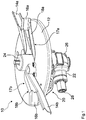
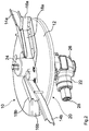
- the Fig. 1 and the Fig. 2 show a distribution device 10 designed as a fertilizer spreader.
- the distribution device 10 comprises a rotatingly driven centrifugal disc 12, onto which the spreading material designed as a fertilizer is applied.
- the throwing blades 14a, 14b, 16a, 16b are arranged on the centrifugal disc.
- the throwing blades 14a, 14b extend essentially radially outward from a cover 24 arranged centrally on the centrifugal disc 12 and each have a projection which projects beyond the centrifugal disc 12.
- the throwing blades 16a, 16b are arranged in the outer region of the centrifugal disc 12 and each adjoin radial recesses 17a, 17b in the centrifugal disc 12.
- the distribution device 10 has two guide elements 18a, 18b which can be moved into the feed area of the centrifugal disc 12 in such a way that the spreading material placed on the centrifugal disc 12 is guided through the guide elements 18a, 18b.
- the guide elements 18a, 18b of the illustrated distribution device 10 are set up to hit the centrifugal disc 12 to level up spreading material from being caught by the throwing blades 14a, 14b.
- the guide elements 18a, 18b serve to steer the spreading material placed on the centrifugal disc 12 onto the throwing blades 16a, 16b. In this way, different throwing patterns, for example for border, edge or wedge spreading, can be realized.
- the two guide elements 18a, 18b are connected to an adjusting device 20, which is set up to adjust the guide elements 18a, 18b accordingly between a retracted state and an extended state.
- the distribution device 10 additionally comprises a housing 22 arranged below the centrifugal disc 12, an input shaft 28 being arranged in sections in the housing 22.
- the input shaft 28 serves for the rotary drive of the centrifugal disc 12.
- a hydraulic connection 26 designed as a connecting piece is connected to the housing 22.
- a hydraulic fluid such as hydraulic oil, can be introduced (concealed) into a drive shaft arranged within the housing 22 and designed as a hollow shaft, the guide elements 18a, 18b ultimately being adjustable via the hydraulic pressure of the hydraulic fluid.
- the guide elements 18a, 18b are in the retracted state.
- An upper surface of the guide elements 18a, 18b has essentially the same shape as the recesses 17a, 17b in the centrifugal disc 12.
- these upper surfaces of the guide elements 18a, 18b close the recesses 17a, 17b in the centrifugal disc 12, so that the grit is prevented from falling through the recesses 17a, 17b in the centrifugal disc 12.
- the spreading material placed on the centrifugal disc 12 is gripped, accelerated and ejected by the throwing blades 14a, 14b.
- the guide elements 18a, 18b are in the extended state.
- a lower surface of the guide elements 18a, 18b has essentially the same shape as the recesses 17a, 17b in the centrifugal disc 12.
- these lower surfaces of the guide elements 18a, 18b close the recesses 17a, 17b in the centrifugal disc 12, so that the grit is prevented from falling through the recesses 17a, 17b in the centrifugal disc 12.
- the guide elements 18a, 18b are in the extended state, the spreading material placed on the centrifugal disc 12 is captured by the guide elements 18a, 18b, which prevent the spreading material placed on the centrifugal disc 12 from being captured by the throwing blades 14a, 14b .
- the guide elements 18a, 18b direct the spreading material placed on the centrifugal disc 12 to the throwing blades 16a, 16b, the throwing blades 16a, 16b ejecting the spreading material.
- the throwing pattern of the spreading material is changed.
- the guide elements 18a, 18b have a substantially U-shaped cross section, so that the guide elements 18a, 18b are designed to be double-curved. Due to the U-shape of the guide elements 18a, 18b, the recesses 17a, 17b in the centrifugal disk 12 are closed in a suitable manner both in the retracted state of the guide elements 18a, 18b and in the extended state of the guide elements 18a, 18b, so that the centrifugal disk spreading material does not fall through the recesses 17a, 17b through the centrifugal disc 12. In addition, the U-shape of the guide elements 18a, 18b allows the guide elements to be extended 18a, 18b a guiding or steering of the spreading material placed on the centrifugal disc 12 in the direction of the throwing blades 16a, 16b.
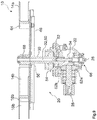
- the Fig. 3 shows that the input shaft 28 is connected to the drive shaft 30 via a bevel gear pair 52a, 52b.
- the drive shaft 30 is set up to drive the centrifugal disc 12 in rotation via the shaft-hub connection 68 and has a recess 32 which extends in the axial direction over the entire length of the drive shaft 30.
- the drive shaft 30 is thus designed as a hollow shaft.
- the drive shaft is mounted radially via the bearing 38 and the bearing 54.
- the bearing 38 is arranged within a receptacle 36, the hydraulic connection 26 also being fastened in the receptacle 36.
- the adjusting device 20 comprises an actuating member 34 which can be moved in sections within the recess 32 of the drive shaft 30 and by means of which the guide elements 18a, 18b can be adjusted.
- the actuator 34 protrudes from the drive shaft 30 on the side facing the centrifugal disc 12.
- the recess 32 in the drive shaft 30 is coupled to the hydraulic connection 26, the actuating member 34 being designed as a piston which can be moved in the axial direction within the recess 32 of the drive shaft 30 by being acted upon by hydraulic pressure.
- the actuator 34 is rotationally coupled to the drive shaft 30, so that the actuator 34 always rotates at the same speed as the drive shaft 30.
- the actuator 34 is connected to a wing element 42 via a fastening element 58 designed as a screw, the Wing element 42 is connected via holding struts 44 to a carrier 46 which can be moved in the vertical direction and which is arranged below the centrifugal disc 12.
- the guide elements 18a, 18b are fastened to the carrier 46 by means of the fastening elements 48 designed as screws, so that an axial movement of the actuating member 34 ultimately results in a movement of the one or more guide elements 18a, 18b into a task area of the centrifugal disc 12 and / or out of the task area the centrifugal disc 12 can cause out. That of the actuator 34 caused movement of the guide elements 18a, 18b is a linear movement in the vertical direction and thus parallel to the axis of rotation of the centrifugal disc 12, wherein the axial movement of the actuator 34 is transmitted to the guide elements 18a, 18b without prior movement conversion.
- guide pins 50 are used which prevent lateral deflection or lateral tilting of the carrier 46.
- the distribution device 10 further comprises a control device (not shown), which is set up to control the hydraulic pressure acting on the actuating member 34.
- the Fig. 4 shows the adjusting device 20 of the distribution device 10 with the guide elements retracted (not shown).
- the hydraulic pressure within the recess 32 of the drive shaft 30 can be increased.
- the actuating member 34 is deflected upward by the increased hydraulic pressure. Because the guide elements are connected to the actuating member 34 via the carrier 46, the holding struts 44, the wing element 42 and the fastening element 58, the pressure increase also causes the guide elements to move upward into the application area of the centrifugal disc 12.
- the Fig. 5 shows the adjusting device 20 of the distribution device 10 with extended guide elements (not shown), which are located in the application area of the centrifugal disc 12. This condition can be maintained by maintaining a constant pressure level. If the hydraulic pressure within the recess 32 of the drive shaft 30 drops again, one or more return springs cause the carrier 46 to move downward, as a result of which the guide elements are moved out of the application area of the centrifugal disc 12.
- Fig. 6 and the Fig. 7 show a further embodiment of the distribution device 10. Unlike that in the 1 to 5 Distribution device 10 is shown Actuator 34 is now rotationally decoupled from the drive shaft 30, namely in such a way that the actuator 34 does not perform any rotational movement during the rotation of the drive shaft 30.
- the actuating member 34 is arranged within an actuating cylinder 66 on the side of the drive shaft 30 facing away from the centrifugal disk 12, the actuating member 34 being movable into the recess 32 of the drive shaft 30 by an axial movement, so that the actuating member 34 extends from the side facing away from the centrifugal disk 12 the drive shaft 30 protrudes.
- a transmission member 60 is also slidably disposed within the recess 32 of the drive shaft 30 and is configured to transmit an axial movement of the actuating member 34 to the guide elements 18b (guide element 18a is not shown).
- An axial bearing 62 is arranged between the actuator 34 and the transmission member 60 due to the speed difference during operation of the distribution device 10. The axial movement is transmitted to the guide elements 18b via a wing element 42 connected to the transmission element 60, holding struts 44 and a carrier 46 on which the guide elements 18b are arranged.
- the guide elements 18b are pulled upward in the case of a linear movement of the actuating member 34 into the application area of the centrifugal disc 12.
- the guide elements 18b are in the retracted state and thus do not influence the ejection of the spreading material placed on the centrifugal disc 12.
- the actuating member 34 can be deflected axially, as a result of which the guide elements 18b are brought into the extended state.
- the guide elements 18b are in the extended state and thus influence the ejection of the the centrifugal disc 12 abandoned grit. Due to the movement of the carrier 46 in the direction of the centrifugal disc 12, return springs 64 were compressed, which cause the guide elements 18b to move out of the application area of the centrifugal disc 12 as soon as the hydraulic pressure within the actuating cylinder 66 falls below a limit pressure.
- the Fig. 8 and the Fig. 9 show a further embodiment of the distribution device 10. Unlike that in the Fig. 6 and 7 Distribution device 10 shown, the guide elements 18a, 18b are pushed upwards in the case of a linear movement into the application area of the centrifugal disc 12. This is achieved by a different coupling of the transmission element 60 to the carrier 46.
- a pin 56 provides direct power transmission between the transmission member 60 and the carrier 46. Vertically extending slots are arranged within the drive shaft 30, the pin 56 extending through the slots. The slots allow the pin 56 to move vertically relative to the drive shaft 30.
- the guide elements 18b are in the retracted state.
- the guide elements 18b are in the extended state.
Landscapes
- Life Sciences & Earth Sciences (AREA)
- Soil Sciences (AREA)
- Environmental Sciences (AREA)
- Fertilizing (AREA)
- Catching Or Destruction (AREA)
Description
- Die Erfindung betrifft ein Verteilgerät für Streugut nach dem Oberbegriff des Patentanspruchs 1.
- Verteilgeräte für Streugut, wie etwa Düngerstreuer, nutzen rotierend antreibbare Schleuderscheiben, um das Streugut zum Auswerfen auf eine Fläche zu beschleunigen.
- Im Bereich von Feldgrenzen, Feldrändern und keilförmig zulaufenden Feldabschnitten ist regelmäßig die Anpassung des Wurfbildes notwendig, um das Streugut möglichst präzise ausbringen zu können. Hierbei ist besonders der Auswurf von Streugut über die Feldgrenzen hinweg zu vermeiden.
- Im Stand der Technik sind bereits Verteilgeräte für Streugut bekannt, welche verstellbare Führungselemente aufweisen, welche dazu eingerichtet sind, das auf die Streuscheibe aufgegebene Streugut zu führen. Über die Verstellung der Führungselemente kann dabei die Anpassung des Wurfbildes erreicht werden.
- Aus der Druckschrift
DE 10 2010 037 935 A1 ist beispielsweise ein Zentrifugaldüngerstreuer bekannt, dessen Wurfschaufeln mittels eines Schwenkbolzens schwenkbar auf den Schleuderscheiben befestigt sind. Die DruckschriftEP 1 618 775 A1 schlägt einen Zentrifugaldüngerstreuer vor, bei welchem die Wurfschaufeln hinsichtlich ihrer wirksamen Länge verstellbar sind. - Darüber hinaus ist aus der Druckschrift
DE 10 2007 021 442 B4 ein Zentrifugaldüngerstreuer bekannt, bei welchem Teile der Wurfschaufeln in vertikaler Richtung senkrecht zur Scheibenebene bewegbar sind. Ferner schlägt die DruckschriftDE 10 2010 060 155 A1 einen Zentrifugaldüngerstreuer vor, bei welchem die Winkelstellung der Wurfschaufeln in der Schleuderscheibenebene verstellt werden kann. - Diese und andere bekannte Lösungen bedingen jedoch eine aufwändige und fehleranfällige Verstelleinrichtung, damit die Führungselemente zum Anpassen des Wurfbildes eingestellt werden können. Ferner sind die einstellbaren Wurfbilder des Streuguts bei den bekannten Lösungen teilweise äußerst beschränkt, sodass eine präzise Ausbringung von Streugut bei komplexen Feldgeometrien nicht ohne Weiteres möglich ist.
- Die der Erfindung zugrunde liegende Aufgabe besteht somit darin, ein Verteilgerät für Streugut bereitzustellen, bei welchem das Wurfbild präzise in weiten Grenzen eingestellt werden kann, wobei die Konstruktion vergleichsweise einfach und robust gegenüber Beschädigungen und Fehlfunktionen ist.
- Die Aufgabe wird gelöst durch ein Verteilgerät der eingangs genannten Art, wobei die Verstelleinrichtung ein zumindest abschnittsweise innerhalb einer Ausnehmung der Antriebswelle in axialer Richtung bewegbares Betätigungsglied umfasst, über welches das eine oder die mehreren Führungselemente verstellbar sind.
- Die Erfindung macht sich die Erkenntnis zunutze, dass durch die Verwendung einer Antriebswelle, welche eine sich in axialer Richtung durch die Antriebswelle erstreckende Ausnehmung aufweist, und die Anordnung eines bewegbaren Betätigungsgliedes innerhalb dieser Ausnehmung eine äußerst robuste und langlebige Konstruktion geschaffen wird, da das Betätigungsglied zum Verstellen des einen oder der mehreren Führungselemente von außen nicht ohne Weiteres zugänglich ist und durch die Ausnehmung in der Antriebswelle vor äußeren Einflüssen und Beanspruchungen, insbesondere auch Stoßbelastungen, geschützt ist. Somit kann eine Wurfbildanpassung erreicht werden, ohne dass hierdurch die Fehler- und/oder Beschädigungsanfälligkeit des Verteilgeräts erhöht wird.
- Vorzugsweise sind auf der Schleuderscheibe zusätzlich zu dem einen oder den mehreren verstellbaren Führungselementen feststehende Wurfschaufeln angeordnet. Das eine oder die mehreren Führungselemente können das Streugut entweder auf die Wurfschaufeln der Schleuderscheibe lenken oder das Streugut direkt auswerfen, sodass dieses nicht in Kontakt mit den auf der Schleuderscheibe angeordneten feststehenden Wurfschaufeln kommt. Durch die Verstellung des einen oder der mehreren Führungselemente können unterschiedliche Wurfbilder realisiert werden. Durch die unterschiedlichen Wurfbilder kann das Verteilgerät zum Grenz-, Rand- oder Keilstreuen eingesetzt werden. Die Abwurfcharakteristik ist außerdem abhängig von dem Aufgabepunkt des Streuguts auf die Schleuderscheibe und der Drehzahl der Schleuderscheibe. Das Verteilgerät kann ein Zentrifugaldüngerstreuer sein.
- In einer besonders bevorzugten Ausführungsform des erfindungsgemäßen Verteilgeräts erstreckt sich die Ausnehmung in der Antriebswelle über die gesamte Länge der Antriebswelle. Somit ist die Antriebswelle als Hohlwelle ausgebildet. Die Ausnehmung weist vorzugsweise einen kreisförmigen Querschnitt auf, wobei der Querschnitt der Ausnehmung über die gesamte Länge der Antriebswelle vorzugsweise gleich ist. Dadurch, dass die Antriebswelle als Hohlwelle ausgebildet ist, wird einerseits Gewicht eingespart und andererseits kann ein druckbeaufschlagtes Fluid, beispielsweise eine Flüssigkeit, ein Gas, oder ein Gasgemisch durch die Antriebswelle geführt werden, sodass das Fluid durch Druckbeaufschlagung zur Verstellung des einen oder der mehreren Führungselemente eingesetzt werden kann.
- In einer vorteilhaften Weiterbildung des erfindungsgemäßen Verteilgeräts ist das Betätigungsglied rotatorisch mit der Antriebswelle gekoppelt. Dadurch, dass das Betätigungsglied rotatorisch mit der Antriebswelle gekoppelt ist, kommt es zu einer Drehbewegung des Betätigungsglieds, wenn die Antriebswelle rotiert. Die rotatorische Kopplung kann derart ausgebildet sein, dass das Betätigungsglied und die Antriebswelle stets mit der gleichen Drehzahl rotieren. In diesem Fall kann das Betätigungsglied beispielsweise über ein Koppelelement, wie beispielsweise einen Stift oder einen Bolzen, mit der Antriebswelle verbunden sein. Alternativ kann die rotatorische Kopplung derart ausgebildet sein, dass Drehzahlunterschiede zwischen dem Betätigungsglied und der Antriebswelle möglich sind. In diesem Fall können beispielsweise Flüssigkeiten oder verdrehbare Kopplungselemente zur rotatorischen Kopplung des Betätigungsglieds und der Antriebswelle eingesetzt werden.
- Erfindungsgemäß ist die Ausnehmung in der Antriebswelle mit einem Hydraulikanschluss gekoppelt, wobei das Betätigungsglied als Kolben ausgebildet ist, welcher durch Beaufschlagung mit Hydraulikdruck innerhalb der Ausnehmung der Antriebswelle in axialer Richtung bewegbar ist. Der Hydraulikanschluss ist vorzugsweise an einem nichtdrehbaren Anschlusselement des Verteilgeräts angeordnet. Vorzugsweise ist der Hydraulikanschluss als Anschlussstutzen ausgebildet, welcher zur Kopplung mit einer Hydraulikleitung ausgebildet ist.
- In einer anderen Ausführungsform des erfindungsgemäßen Verteilgeräts ist das Betätigungsglied als Bestandteil einer hydraulischen Betätigungseinrichtung ausgebildet, wobei das Betätigungsglied hydraulisch innerhalb der Ausnehmung der Antriebswelle in axialer Richtung bewegbar ist. Wenn das Betätigungsglied als Bestandteil einer hydraulischen Betätigungseinrichtung ausgebildet ist, kann das Betätigungsglied durch eine Hydraulikflüssigkeit innerhalb der Ausnehmung der Antriebswelle in axialer Richtung bewegt werden. Wenn das Betätigungsglied als Bestandteil einer nicht erfindungsgemäßen pneumatischen Betätigungseinrichtung ausgebildet ist, kann das Betätigungsglied durch ein Gas oder Gasgemisch innerhalb der Ausnehmung der Antriebswelle in axialer Richtung bewegt werden. Wenn das Betätigungsglied als Bestandteil einer nicht erfindungsgemäßen elektrischen Betätigungseinrichtung ausgebildet ist, kann das Betätigungsglied über einen Elektromotor, beispielsweise einen Linearmotor, innerhalb der Ausnehmung der Antriebswelle in axialer Richtung bewegt werden.
- Vorteilhaft ist ferner ein erfindungsgemäßes Verteilgerät, bei welchem das Betätigungsglied zumindest in einem Zustand der Verstelleinrichtung aus der der Schleuderscheibe zugewandten Seite der Antriebswelle herausragt. Beispielsweise ist die Ausnehmung der Antriebswelle auf der der Schleuderscheibe abgewandten Seite in diesem Fall mit einer Hydraulikflüssigkeit, einem Gas oder einem Gasgemisch gefüllt, wobei über eine Druckregelung der Hydraulikflüssigkeit, des Gases oder des Gasgemisches das Betätigungsglied aus der Antriebswelle heraus und/oder in die Antriebswelle hinein bewegt werden kann.
- In einer besonders bevorzugten Ausführungsform des erfindungsgemäßen Verteilgeräts ist das Betätigungsglied von der Antriebswelle rotatorisch entkoppelt. Beispielsweise kann das Betätigungsglied nicht-drehbar ausgebildet sein oder eine von der Antriebswelle unabhängige Rotationscharakteristik aufweisen. Bevorzugt ist außerdem ein erfindungsgemäßes Verteilgerät, bei welchem das Betätigungsglied innerhalb eines Betätigungszylinders auf der der Schleuderscheibe abgewandten Seite der Antriebswelle angeordnet ist. Das Betätigungsglied ist vorzugsweise als Kolben des Betätigungszylinders ausgebildet. Der Betätigungszylinder ist ein hydraulisch ansteuerbarer Zylinder. Der Betätigungszylinder kann als doppelt wirkender Zylinder ausgebildet sein, sodass das eine oder die mehreren Führungselemente mittels des Betätigungszylinders nach dem Hineinbewegen in den Aufgabebereich der Schleuderscheibe auch wieder aus dem Aufgabebereich der Schleuderscheibe heraus bewegt werden können. Alternativ oder zusätzlich können zum Bewegen des einen oder der mehreren Führungselemente aus dem Aufgabebereich der Schleuderscheibe heraus eine oder mehrere Rückstellfedern eingesetzt werden.
- In einer anderen bevorzugten Ausführungsform des erfindungsgemäßen Verteilgeräts ist das Betätigungsglied derart von der Antriebswelle rotatorisch entkoppelt, dass das Betätigungsglied während der Rotation der Antriebswelle keine Drehbewegung ausführt. Durch eine derartige Entkopplung des Betätigungsglieds von der Antriebswelle kann zum Abdichten des Betätigungsglieds auf die Verwendung einer dynamischen Dichtung verzichtet werden, welche Rotationsbewegungen aufnehmen muss. Ferner wird dadurch, dass eine Drehbewegung des Betätigungsglieds nicht stattfindet, die Momentenbelastung des Betätigungsglieds erheblich reduziert, wodurch die Beschädigungsanfälligkeit verringert wird.
- Eine Weiterbildung des erfindungsgemäßen Verteilgeräts weist ein zumindest abschnittsweise innerhalb der Ausnehmung der Antriebswelle angeordnetes Übertragungsglied auf, welches dazu eingerichtet ist, eine Axialbewegung des Betätigungsglieds an das eine oder die mehreren Führungselemente oder an einen mit dem einen oder den mehreren Führungselementen verbundenen Bewegungsumwandler zu übertragen. Zur Übertragung der Axialbewegung des Betätigungsglieds steht das Übertragungsglied vorzugsweise mit dem Betätigungsglied, insbesondere innerhalb der Ausnehmung der Antriebswelle, in Kontakt. Der Bewegungsumwandler kann die Axialbewegung des Betätigungsglieds und des Übertragungsglieds in eine andere Bewegungsform, wie beispielsweise eine Schwenkbewegung oder eine Radialbewegung, umformen. Auf diese Weise kann durch eine Axialbewegung des Betätigungsglieds ein Verschwenken des einen oder der mehreren Führungselemente und/oder ein radiales Verfahren des einen oder der mehreren Führungselemente auf der Schleuderscheibe realisiert werden.
- Außerdem ist ein erfindungsgemäßes Verteilgerät bevorzugt, bei welchem zwischen dem Betätigungsglied und dem Übertragungsglied ein Axiallager angeordnet ist. Vorzugsweise ist das Übertragungsglied rotatorisch mit der Antriebswelle gekoppelt. Dadurch, dass das Betätigungsglied rotatorisch von der Antriebswelle entkoppelt ist, weisen das Betätigungsglied und das Übertragungsglied unterschiedliche Drehzahlen während des Betriebs des Verteilgeräts auf. Damit der Drehzahlunterschied zwischen dem Betätigungsglied und dem Übertragungsglied ausgeglichen werden kann, wird ein Axiallager eingesetzt. Alternativ können das Betätigungsglied und das Übertragungsglied auch eine andere geeignete Kopplung aufweisen, welche die Axialkraftübertragung erlaubt und gleichzeitig Drehzahlunterschiede aufnehmen kann. Beispielsweise weisen das Betätigungsglied und das Übertragungsglied in Kontakt stehende gehärtete Enden auf, wobei ein Ende in Kugelform und das andere Ende in Pfannenform ausgebildet ist. Diese Ausführung führt zu einer zusätzlichen Platzeinsparung und eignet sich insbesondere zur Umsetzung von bauraumoptimierten Verteilgeräten.
- Außerdem ist ein erfindungsgemäßes Verteilgerät bevorzugt, bei welchem das Betätigungsglied und/oder das Übertragungsglied zumindest in einem Zustand der Verstelleinrichtung aus der der Schleuderscheibe abgewandten Seite der Antriebswelle herausragt. Vorzugsweise ragen das Betätigungsglied und/oder das Übertragungsglied in dem zumindest einen Zustand der Verstelleinrichtung aus der Antriebswelle in ein Getriebegehäuse hinein, wobei innerhalb des Getriebegehäuses ein mit der Antriebswelle verbundenes Kegelradpaar zum Antreiben der Antriebswelle angeordnet ist.
- In einer weiteren bevorzugten Ausführungsform des erfindungsgemäßen Verteilgeräts verursacht eine Axialbewegung des Betätigungsglieds eine Bewegung des einen oder der mehreren Führungselemente in einen Aufgabebereich der Schleuderscheibe hinein und/oder aus dem Aufgabebereich der Schleuderscheibe heraus. Im Aufgabebereich der Schleuderscheibe wird das aufgegebene Streugut durch das eine oder die mehreren Führungselemente und/oder durch feststehende Wurfschaufeln beschleunigt und letztendlich ausgeworfen. Vorzugsweise verursacht die Axialbewegung des Betätigungsglieds eine Bewegung des einen oder der mehreren Betätigungselemente in den Aufgabebereich der Schleuderscheibe hinein, wobei die Bewegung des einen oder der mehreren Führungselemente aus dem Aufgabebereich der Schleuderscheibe heraus durch eine oder mehrere Rückstellfedern verursacht wird. Die eine oder die mehreren Rückstellfedern verursachen dabei eine Bewegung des einen oder der mehreren Führungselemente aus dem Aufgabebereich der Schleuderscheibe heraus, wenn die Rückstellkraft der einen oder der mehreren Rückstellfedern die auf das Betätigungsglied wirkende Betätigungskraft übersteigt.
- Außerdem ist ein erfindungsgemäßes Verteilgerät bevorzugt, bei welchem die Bewegung des einen oder der mehreren Führungselemente eine Linearbewegung, vorzugsweise parallel zu der Rotationsachse der Schleuderscheibe, und/oder eine Schwenkbewegung des einen oder der mehreren Führungselemente umfasst. Bei einer Linearbewegung des einen oder der mehreren Führungselemente wird die Axialbewegung des Betätigungsglieds vorzugsweise ohne vorherige Bewegungsumwandlung an das eine oder die mehreren Führungselemente übertragen. Bei einer Schwenkbewegung des einen oder der mehreren Führungselemente wird die Axialbewegung des Betätigungsglieds vorzugsweise mit einer vorherigen Bewegungsumwandlung an das eine oder die mehreren Führungselemente übertragen. Demnach kann das eine oder können die mehreren Führungselemente durch eine Hubbewegung in den Aufgabebereich der Schleuderscheibe hineingefahren werden und/oder durch eine Schwenkbewegung in den Aufgabebereich der Schleuderscheibe hineingekippt und/oder gedreht werden.
- In einer anderen bevorzugten Ausführungsform des erfindungsgemäßen Verteilgeräts wird das eine oder werden die mehreren Führungselemente bei einer Linearbewegung des Betätigungsglieds in den Aufgabebereich der Schleuderscheibe nach oben geschoben oder nach oben gezogen. Wenn das eine oder die mehreren Führungselemente bei einer Linearbewegung des Betätigungsglieds in den Aufgabebereich der Schleuderscheibe nach oben geschoben werden, ist in dem Übertragungsglied ein Koppelelement, wie etwa ein Stift oder ein Bolzen, angeordnet, welches die Bewegung des Übertragungsglieds unterhalb der Schleuderscheibe an das eine oder die mehreren Führungselemente oder ein das eine oder die mehreren Führungselemente tragendes Trägerteil übergibt. Wenn das eine oder die mehreren Führungselemente bei einer Linearbewegung des Betätigungsglieds in den Aufgabebereich der Schleuderscheibe nach oben gezogen werden, überträgt ein Koppelelement die Bewegung des Übertragungsglieds oberhalb der Schleuderscheibe auf das eine oder die mehreren Führungselemente oder eine das eine oder die mehreren Führungselemente umfassende Baugruppe.
- In einer anderen bevorzugten Ausführungsform der erfindungsgemäßen Verteilmaschine ist das eine oder sind die mehreren Führungselemente einfach oder mehrfach gebogen ausgebildet. Vorzugsweise weisen die Führungselemente eine U-Form oder eine L-Form auf. Vorzugsweise erstreckt sich das eine oder erstrecken sich die mehreren Führungselemente durch eine Ausnehmung in der Schleuderscheibe. Durch eine gebogene Ausbildung des einen oder der mehreren Führungselemente kann somit einerseits eine vertikale Führung des aufgegebenen Streuguts erreicht werden und andererseits die Ausnehmung oder die Ausnehmungen, durch welche sich das eine oder die mehreren Führungselemente erstrecken, geschlossen werden, wenn das eine oder die mehreren Führungselemente nicht in den Aufgabebereich der Schleuderscheibe hineinragen.
- Das erfindungsgemäße Verteilgerät wird ferner durch eine Steuerungseinrichtung vorteilhaft weitergebildet, welche dazu eingerichtet ist, den auf das Betätigungsglied wirkenden Hydraulikdruck zu steuern. Die Steuerung des Hydraulikdrucks kann dabei beispielsweise selbsttätig in Abhängigkeit einer erfassten Feldgeometrie bzw. einer erfassten Feldform erfolgen. Alternativ oder zusätzlich kann die Steuerung des Hydraulikdrucks auch einer ausgewählten Ausbringroutine folgen.
- Ferner ist ein erfindungsgemäßes Verteilgerät bevorzugt, dessen Steuerungseinrichtung dazu eingerichtet ist, die hydraulische Betätigungseinhchtung zu steuern. In diesem Fall ist die Steuerungseinrichtung vorzugsweise dazu eingerichtet, den Hydraulikdruck einer Hydraulikflüssigkeit zu steuern. Außerhalb des Erfindungsgegenstands ist die Steuerungseinrichtung alternativ dazu eingerichtet, den Pneumatikdruck eines Gases oder eine Gasgemisches oder einen Elektromotor der Betätigungseinrichtung zu steuern.
- Weitere Einzelheiten der Erfindung sind der Figurenbeschreibung und den Zeichnungen zu entnehmen. Es zeigen
- Fig. 1
- ein erfindungsgemäßes Verteilgerät in einem ersten Zustand in einer perspektivischen Darstellung;
- Fig. 2
- das in der
Fig. 1 dargestellte Verteilgerät in einem zweiten Zustand in einer perspektivischen Darstellung; - Fig. 3
- das in der
Fig. 1 dargestellte Verteilgerät in dem ersten Zustand in einer Schnittdarstellung; - Fig. 4
- die Verstelleinrichtung des in der
Fig. 1 dargestellten Verteilgeräts in dem ersten Zustand in einer Schnittdarstellung; - Fig. 5
- die Verstelleinrichtung des in der
Fig. 1 dargestellten Verteilgeräts in dem zweiten Zustand in einer Schnittdarstellung; - Fig. 6
- ein erfindungsgemäßes Verteilgerät in einem ersten Zustand in einer Schnittdarstellung;
- Fig. 7
- das in der
Fig. 6 dargestellte Verteilgerät in einem zweiten Zustand in einer Schnittdarstellung; - Fig. 8
- ein erfindungsgemäßes Verteilgerät in einem ersten Zustand in einer Schnittdarstellung; und
- Fig. 9
- das in der
Fig. 8 dargestellte Verteilgerät in einem zweiten Zustand in einer Schnittdarstellung. - Die
Fig. 1 und dieFig. 2 zeigen einen als Düngerstreuer ausgebildetes Verteilgerät 10. Das Verteilgerät 10 umfasst eine rotierend antreibbare Schleuderscheibe 12, auf welche das als Dünger ausgebildete Streugut aufgegeben wird. - Auf der Schleuderscheibe sind zwei Paare von feststehenden Wurfschaufeln 14a, 14b, 16a, 16b angeordnet. Die Wurfschaufeln 14a, 14b erstecken sich von einem mittig auf der Schleuderscheibe 12 angeordneten Deckel 24 im Wesentlichen radial nach außen und weisen jeweils einen Überstand auf, welcher über die Schleuderscheibe 12 hinausragt. Die Wurfschaufeln 16a, 16b sind im Außenbereich der Schleuderscheibe 12 angeordnet und schließen sich jeweils an radial innenliegende Ausnehmungen 17a, 17b in der Schleuderscheibe 12 an.
- Außerdem weist das Verteilgerät 10 zwei Führungselemente 18a, 18b auf, welche derart in den Aufgabebereich der Schleuderscheibe 12 hinein bewegbar sind, dass das auf die Schleuderscheibe 12 aufgegebene Streugut durch die Führungselemente 18a, 18b geführt wird. Die Führungselemente 18a, 18b des dargestellten Verteilgeräts 10 sind in diesem Fall dazu eingerichtet, das auf die Schleuderscheibe 12 aufgebebene Streugut daran zu hindern, von den Wurfschaufeln 14a, 14b erfasst zu werden. Vielmehr dienen die Führungselemente 18a, 18b um Lenken des auf die Schleuderscheibe 12 aufgegebenen Streuguts auf die Wurfschaufeln 16a, 16b. Hierdurch können unterschiedliche Wurfbilder, beispielsweise zum Grenz-, Rand- oder Keilstreuen, realisiert werden.
- Die zwei Führungselemente 18a, 18b sind mit einer Verstelleinrichtung 20 verbunden, welche dazu eingerichtet ist, die Führungselemente 18a, 18b entsprechend zwischen einem eingefahrenen Zustand und einem ausgefahrenen Zustand zu verstellen.
- Das Verteilgerät 10 umfasst zusätzlich ein unterhalb der Schleuderscheibe 12 angeordnetes Gehäuse 22, wobei eine Eingangswelle 28 abschnittsweise in dem Gehäuse 22 angeordnet ist. Die Eingangswelle 28 dient dem rotatorischen Antrieb der Schleuderscheibe 12. Außerdem ist ein als Anschlussstutzen ausgebildeter Hydraulikanschluss 26 mit dem Gehäuse 22 verbunden. Über den Hydraulikanschluss 26 ist eine Hydraulikflüssigkeit, wie etwa Hydrauliköl, in eine innerhalb des Gehäuses 22 angeordnete und als Hohlwelle ausgebildete Antriebswelle (verdeckt) einleitbar, wobei über den Hydraulikdruck der Hydraulikflüssigkeit letztendlich die Führungselemente 18a, 18b verstellbar sind.
- In dem in der
Fig. 1 dargestellten Zustand befinden Sie die Führungselemente 18a, 18b in dem eingefahrenen Zustand. Eine obere Fläche der Führungselemente 18a, 18b weist im Wesentlichen die gleiche Form wie die Ausnehmungen 17a, 17b in der Schleuderscheibe 12 auf. In dem eingefahrenen Zustand verschließen diese oberen Flächen der Führungselemente 18a, 18b die Ausnehmungen 17a, 17b in der Schleuderscheibe 12, sodass ein Durchfallen des Streuguts durch die Ausnehmungen 17a, 17b in der Schleuderscheibe 12 im Wesentlichen verhindert ist. - Dadurch, dass sich die Führungselemente 18a, 18b in dem eingefahrenen Zustand befinden, wird das auf die Schleuderscheibe 12 aufgegebene Streugut von den Wurfschaufeln 14a, 14b erfasst, beschleunigt und ausgeworfen.
- In dem in der
Fig. 2 dargestellten Zustand befinden Sie die Führungselemente 18a, 18b in dem ausgefahrenen Zustand. Eine untere Fläche der Führungselemente 18a, 18b weist im Wesentlichen die gleiche Form wie die Ausnehmungen 17a, 17b in der Schleuderscheibe 12 auf. In dem ausgefahrenen Zustand verschließen diese unteren Flächen der Führungselemente 18a, 18b die Ausnehmungen 17a, 17b in der Schleuderscheibe 12, sodass ein Durchfallen des Streuguts durch die Ausnehmungen 17a, 17b in der Schleuderscheibe 12 im Wesentlichen verhindert ist. - Dadurch, dass sich die Führungselemente 18a, 18b in dem ausgefahrenen Zustand befinden, wird das auf die Schleuderscheibe 12 aufgegebene Streugut von den Führungselementen 18a, 18b erfasst, welche verhindern, dass das auf die Schleuderscheibe 12 aufgegebene Streugut von den Wurfschaufeln 14a, 14b erfasst wird. Die Führungselemente 18a, 18b lenken das auf die Schleuderscheibe 12 aufgegebene Streugut zu den Wurfschaufeln 16a, 16b, wobei die Wurfschaufeln 16a, 16b das Streugut auswerfen.
- Durch die abweichende Position und Ausrichtung sowie den sich unterscheidenden Überstand über die Schleuderscheibe 12 der Wurfschaufeln 16a, 16b im Vergleich zu den Wurfschaufeln 14a, 14b wird das Wurfbild des Streuguts verändert.
- Die Führungselemente 18a, 18b weisen einen im Wesentlichen U-förmigen Querschnitt auf, sodass die Führungselemente 18a, 18b doppelt gebogen ausgebildet sind. Durch die U-Form der Führungselemente 18a, 18b werden die Ausnehmungen 17a, 17b in der Schleuderscheibe 12 sowohl in dem eingefahrenen Zustand der Führungselemente 18a, 18b als auch in dem ausgefahrenen Zustand der Führungselemente 18a, 18b in geeigneter Weise verschlossen, sodass auf die Schleuderscheibe aufgegebenes Streugut nicht durch die Ausnehmungen 17a, 17b durch die Schleuderscheibe 12 fällt. Außerdem erlaubt die U-Form der Führungselemente 18a, 18b in dem ausgefahrenen Zustand der Führungselemente 18a, 18b ein Führen beziehungsweise Lenken des auf die Schleuderscheibe 12 aufgegebenen Streuguts in Richtung der Wurfschaufeln 16a, 16b.
- Die
Fig. 3 zeigt, dass die Eingangswelle 28 über ein Kegelradpaar 52a, 52b mit der Antriebswelle 30 verbunden ist. Die Antriebswelle 30 ist dazu eingerichtet, die Schleuderscheibe 12 über die Welle-Nabe-Verbindung 68 rotierend anzutreiben und weist eine sich in axialer Richtung über die gesamte Länge der Antriebswelle 30 erstreckende Ausnehmung 32 auf. Somit ist die Antriebswelle 30 als Hohlwelle ausgebildet. Die Radiallagerung der Antriebswelle erfolgt über das Lager 38 und das Lager 54. Das Lager 38 ist innerhalb einer Aufnahme 36 angeordnet, wobei der Hydraulikanschluss 26 ebenfalls in der Aufnahme 36 befestigt ist. - Die Verstelleinrichtung 20 umfasst ein abschnittsweise innerhalb der Ausnehmung 32 der Antriebswelle 30 in axialer Richtung bewegbares Betätigungsglied 34, über welches die Führungselemente 18a, 18b verstellbar sind. Das Betätigungsglied 34 ragt auf der der Schleuderscheibe 12 zugewandten Seite aus der Antriebswelle 30 heraus. Die Ausnehmung 32 in der Antriebswelle 30 ist mit dem Hydraulikanschluss 26 gekoppelt, wobei das Betätigungsglied 34 als Kolben ausgebildet ist, welcher durch Beaufschlagung mit Hydraulikdruck innerhalb der Ausnehmung 32 der Antriebswelle 30 in axialer Richtung bewegbar ist.
- Über den Fortsatz 40 ist das Betätigungsglied 34 rotatorisch mit der Antriebswelle 30 koppelt, sodass das Betätigungsglied 34 stets mit der gleichen Drehzahl rotiert wie die Antriebswelle 30. Außerdem ist das Betätigungsglied 34 über ein als Schraube ausgebildetes Befestigungselement 58 mit einem Flügelelement 42 verbunden, wobei das Flügelelement 42 über Haltestreben 44 mit einem in vertikaler Richtung bewegbaren Träger 46 verbunden ist, welcher unterhalb der Schleuderscheibe 12 angeordnet ist. Mittels der als Schrauben ausgebildeten Befestigungselemente 48 sind die Führungselemente 18a, 18b an dem Träger 46 befestigt, sodass eine Axialbewegung des Betätigungsglieds 34 letztendlich eine Bewegung des einen oder der mehreren Führungselemente 18a, 18b in einen Aufgabebereich der Schleuderscheibe 12 hinein und/oder aus dem Aufgabebereich der Schleuderscheibe 12 heraus verursachen kann. Die von dem Betätigungsglieds 34 verursachte Bewegung der Führungselemente 18a, 18b ist eine Linearbewegung in vertikaler Richtung und somit parallel zu der Rotationsachse der Schleuderscheibe 12, wobei die Axialbewegung des Betätigungsglieds 34 ohne vorherige Bewegungsumwandlung an die Führungselemente 18a, 18b übertragen wird. Zur Führung des Trägers 46 und der auf dem Träger 46 befestigten Führungselemente 18a, 18b werden Führungsstifte 50 eingesetzt, welche ein seitliches Auslenken oder ein seitliches Kippen des Trägers 46 verhindern.
- Das Verteilgerät 10 umfasst ferner eine Steuerungseinrichtung (nicht dargestellt), welche dazu eingerichtet ist, den auf das Betätigungsglied 34 wirkenden Hydraulikdruck zu steuern.
- Die
Fig. 4 zeigt die Verstelleinrichtung 20 des Verteilgeräts 10 bei eingefahrenen Führungselementen (nicht dargestellt). Ausgehend von dem in derFig. 4 dargestellten Zustand kann der Hydraulikdruck innerhalb der Ausnehmung 32 der Antriebswelle 30 erhöht werden. Durch den erhöhten Hydraulikdruck wird das Betätigungsglied 34 nach oben ausgelenkt. Dadurch, dass die Führungselemente über den Träger 46, die Haltestreben 44, das Flügelelement 42 und das Befestigungselement 58 mit dem Betätigungsglied 34 verbunden ist, verursacht die Druckerhöhung somit auch eine Aufwärtsbewegung der Führungselemente in den Aufgabebereich der Schleuderscheibe 12 hinein. - Die
Fig. 5 zeigt die Verstelleinrichtung 20 des Verteilgeräts 10 bei ausgefahrenen Führungselementen (nicht dargestellt), welche sich in dem Aufgabebereich der Schleuderscheibe 12 befinden. Dieser Zustand kann durch das Halten eines konstanten Druckniveaus gehalten werden. Fällt der Hydraulikdruck innerhalb der Ausnehmung 32 der Antriebswelle 30 wieder ab, verursacht eine oder verursachen mehrere Rückstellfedern eine Abwärtsbewegung des Trägers 46, wodurch die Führungselemente aus dem Aufgabebereich der Schleuderscheibe 12 heraus bewegt werden. - Die
Fig. 6 und dieFig. 7 zeigen eine weitere Ausführungsform des Verteilgeräts 10. Anders als bei dem in denFig. 1 bis 5 dargestellten Verteilgerät 10 ist das Betätigungsglied 34 nun von der Antriebswelle 30 rotatorisch entkoppelt, nämlich derart, dass das Betätigungsglied 34 während der Rotation der Antriebswelle 30 keine Drehbewegung ausführt. - Das Betätigungsglied 34 ist innerhalb eines Betätigungszylinders 66 auf der der Schleuderscheibe 12 abgewandten Seite der Antriebswelle 30 angeordnet, wobei der Betätigungsglied 34 durch eine Axialbewegung in die Ausnehmung 32 der Antriebswelle 30 hinein bewegbar ist, sodass das Betätigungsglied 34 aus der der Schleuderscheibe 12 abgewandten Seite aus der Antriebswelle 30 herausragt.
- Innerhalb der Ausnehmung 32 der Antriebswelle 30 ist außerdem ein Übertragungsglied 60 verschiebbar angeordnet, welches dazu eingerichtet ist, eine Axialbewegung des Betätigungsglieds 34 an die Führungselemente 18b (Führungselement 18a ist nicht dargestellt) zu übertragen. Zwischen dem Betätigungsglied 34 und dem Übertragungsglied 60 ist aufgrund der Drehzahldifferenz im Betrieb des Verteilgeräts 10 ein Axiallager 62 angeordnet. Die Übertragung der Axialbewegung auf die Führungselemente 18b erfolgt über ein mit dem Übertragungsglied 60 verbundenes Flügelelement 42, Haltestreben 44 und einen Träger 46, auf welchem die Führungselemente 18b angeordnet sind.
- Bei der dargestellten Ausführungsform werden die Führungselemente 18b bei einer Linearbewegung des Betätigungsglieds 34 in den Aufgabebereich der Schleuderscheibe 12 nach oben gezogen.
- In dem in der
Fig. 6 dargestellten Zustand befinden sich die Führungselemente 18b in dem eingefahrenen Zustand und beeinflussen somit nicht den Auswurf des auf die Schleuderscheibe 12 aufgegebenen Streuguts. Durch eine Druckerhöhung innerhalb des Betätigungszylinders 66 kann das Betätigungsglied 34 axial ausgelenkt werden, wodurch die Führungselemente 18b in den ausgefahrenen Zustand überführt werden. - In dem in der
Fig. 7 dargestellten Zustand befinden sich die Führungselemente 18b in dem ausgefahrenen Zustand und beeinflussen somit den Auswurf des auf die Schleuderscheibe 12 aufgegebenen Streuguts. Durch die Bewegung des Trägers 46 in Richtung der Schleuderscheibe 12 wurden Rückstellfedern 64 gestaucht, welche ein Herausbewegen der Führungselemente 18b aus dem Aufgabebereich der Schleuderscheibe 12 verursachen, sobald der Hydraulikdruck innerhalb des Betätigungszylinders 66 einen Grenzdruck unterschreitet. - Die
Fig. 8 und dieFig. 9 zeigen eine weitere Ausführungsform des Verteilgeräts 10. Anders als bei dem in denFig. 6 und7 dargestellten Verteilgerät 10 werden die Führungselemente 18a, 18b bei einer Linearbewegung in den Aufgabebereich der Schleuderscheibe 12 nach oben geschoben. Dies wird durch eine abweichende Kopplung des Übertragungsglieds 60 mit dem Träger 46 realisiert. Ein Stift 56 sorgt für eine direkte Kraftübertragung zwischen dem Übertragungsglied 60 und dem Träger 46. Innerhalb der Antriebwelle 30 sind vertikal verlaufende Schlitze angeordnet, wobei sich der Stift 56 durch die Schlitze erstreckt. Die Schlitze erlauben eine vertikale Bewegung des Stifts 56 relativ zur Antriebswelle 30. - In dem in der
Fig. 8 dargestellten Zustand befinden sich die Führungselemente 18b in dem eingefahrenen Zustand. In dem in derFig. 9 dargestellten Zustand befinden sich die Führungselemente 18b in dem ausgefahrenen Zustand. -
- 10
- Verteilgerät
- 12
- Schleuderscheibe
- 14a, 14b
- Wurfschaufeln
- 16a, 16b
- Wurfschaufeln
- 17a, 17b
- Ausnehmungen
- 18a, 18b
- Führungselemente
- 20
- Verstelleinrichtung
- 22
- Gehäuse
- 24
- Deckel
- 26
- Hydraulikanschluss
- 28
- Eingangswelle
- 30
- Antriebswelle
- 32
- Ausnehmung
- 34
- Betätigungsglied
- 36
- Aufnahme
- 38
- Lager
- 40
- Fortsatz
- 42
- Flügelelement
- 44
- Haltestreben
- 46
- Träger
- 48
- Befestigungselemente
- 50
- Führungsstift
- 52a, 52b
- Kegelradpaar
- 54
- Lager
- 56
- Stift
- 58
- Befestigungselement
- 60
- Übertragungsglied
- 62
- Axiallager
- 64
- Rückstellfeder
- 66
- Betätigungszylinder
- 68
- Welle-Nabe-Verbindung
Claims (17)
- Verteilgerät (10) für Streugut, insbesondere Düngerstreuer, mit- zumindest einer rotierend antreibbaren Schleuderscheibe (12);- einem oder mehreren verstellbaren Führungselementen (18a, 18b), welche dazu eingerichtet sind, das auf die Schleuderscheibe (12) aufgegebene Streugut zu führen;- einer Antriebswelle (30), welche eine sich in axialer Richtung durch die Antriebswelle (30) erstreckende Ausnehmung (32) aufweist und dazu eingerichtet ist, die Schleuderscheibe (12) rotierend anzutreiben; und- einer Verstelleinrichtung (20), welche dazu eingerichtet ist, das eine oder die mehreren Führungselemente (18a, 18b) zu verstellen,
wobei die Verstelleinrichtung (20) ein zumindest abschnittsweise innerhalb der Ausnehmung (32) der Antriebswelle (30) in axialer Richtung bewegbares Betätigungsglied (34) umfasst, über welches das eine oder die mehreren Führungselemente (18a, 18b) verstellbar sind, dadurch gekennzeichnet, dass die Ausnehmung (32) in der Antriebswelle (30) mit einem Hydraulikanschluss (26) gekoppelt ist, wobei das Betätigungsglied (34) als Kolben ausgebildet ist, welcher durch Beaufschlagung mit Hydraulikdruck innerhalb der Ausnehmung (32) der Antriebswelle (30) in axialer Richtung bewegbar ist. - Verteilgerät (10) nach Anspruch 1,
dadurch gekennzeichnet, dass die Ausnehmung (32) in der Antriebswelle (30) sich über die gesamte Länge der Antriebswelle (30) erstreckt. - Verteilgerät (10) nach Anspruch 1 oder 2,
dadurch gekennzeichnet, dass das Betätigungsglied (34) rotatorisch mit der Antriebswelle (30) gekoppelt ist. - Verteilgerät (10) nach einem der vorstehenden Ansprüche,
dadurch gekennzeichnet, dass das Betätigungsglied (34) als Bestandteil einer hydraulischen Betätigungseinrichtung ausgebildet ist, wobei das Betätigungsglied (34) hydraulisch innerhalb der Ausnehmung (32) der Antriebswelle (30) in axialer Richtung bewegbar ist. - Verteilgerät (10) nach einem der vorstehenden Ansprüche,
dadurch gekennzeichnet, dass das Betätigungsglied (34) zumindest in einem Zustand der Verstelleinrichtung (20) aus der der Schleuderscheibe (12) zugewandten Seite der Antriebswelle (30) herausragt. - Verteilgerät (10) nach Anspruch 1 oder 2,
dadurch gekennzeichnet, dass das Betätigungsglied (34) von der Antriebswelle (30) rotatorisch entkoppelt ist. - Verteilgerät (10) nach Anspruch 6,
dadurch gekennzeichnet, dass das Betätigungsglied (34) innerhalb eines Betätigungszylinders (66) auf der der Schleuderscheibe (12) abgewandten Seite der Antriebswelle (30) angeordnet ist. - Verteilgerät (10) nach Anspruch 6 oder 7,
dadurch gekennzeichnet, dass das Betätigungsglied (34) derart von der Antriebswelle (30) rotatorisch entkoppelt ist, dass das Betätigungsglied (34) während der Rotation der Antriebswelle (30) keine Drehbewegung ausführt. - Verteilgerät (10) nach einem der vorstehenden Ansprüche,
gekennzeichnet durch ein zumindest abschnittsweise innerhalb der Ausnehmung (32) der Antriebswelle (30) angeordnetes Übertragungsglied (60), welches dazu eingerichtet ist, eine Axialbewegung des Betätigungsglieds (34) an das eine oder die mehreren Führungselemente (18a, 18b) oder an einen mit dem einen oder den mehreren Führungselementen (18a, 18b) verbundenen Bewegungsumwandler zu übertragen. - Verteilgerät (10) nach Anspruch 9,
dadurch gekennzeichnet, dass zwischen dem Betätigungsglied (34) und dem Übertragungsglied (60) ein Axiallager (62) angeordnet ist. - Verteilgerät (10) nach Anspruch 9 oder 10,
dadurch gekennzeichnet, dass das Betätigungsglied (34) und/oder das Übertragungsglied (60) zumindest in einem Zustand der Verstelleinrichtung (20) aus der der Schleuderscheibe (12) abgewandten Seite aus der Antriebswelle (30) herausragt. - Verteilgerät (10) nach einem der vorstehenden Ansprüche,
dadurch gekennzeichnet, dass eine Axialbewegung des Betätigungsglieds (34) eine Bewegung des einen oder der mehreren Führungselemente (18a, 18b) in einen Aufgabebereich der Schleuderscheibe (12) hinein und/oder aus dem Aufgabebereich der Schleuderscheibe (12) heraus verursacht. - Verteilgerät (10) nach Anspruch 12,
dadurch gekennzeichnet, dass die Bewegung des einen oder der mehreren Führungselemente (18a, 18b) eine Linearbewegung, vorzugsweise parallel zu der Rotationsachse der Schleuderscheibe (12), und/oder eine Schwenkbewegung des einen oder der mehreren Führungselemente (18a, 18b) umfasst. - Verteilgerät (10) nach Anspruch 12 oder 13,
dadurch gekennzeichnet, dass das eine oder die mehreren Führungselemente (18a, 18b) bei einer Linearbewegung in den Aufgabebereich der Schleuderscheibe (12) nach oben geschoben oder nach oben gezogen werden. - Verteilgerät (10) nach einem der vorstehenden Ansprüche,
dadurch gekennzeichnet, dass das eine oder die mehreren Führungselemente (18a, 18b) einfach oder mehrfach gebogen ausgebildet sind. - Verteilgerät (10) nach einem der vorstehenden Ansprüche,
gekennzeichnet durch eine Steuerungseinrichtung, welche dazu eingerichtet ist, den auf das Betätigungsglied (34) wirkenden Hydraulikdruck zu steuern. - Verteilgerät (10) nach zumindest Anspruch 4,
gekennzeichnet durch eine Steuerungseinrichtung, welche dazu eingerichtet ist, die hydraulische Betätigungseinrichtung zu steuern.
Applications Claiming Priority (1)
| Application Number | Priority Date | Filing Date | Title |
|---|---|---|---|
| DE102017114975.9A DE102017114975A1 (de) | 2017-07-05 | 2017-07-05 | Verteilgerät für Streugut |
Publications (2)
| Publication Number | Publication Date |
|---|---|
| EP3424290A1 EP3424290A1 (de) | 2019-01-09 |
| EP3424290B1 true EP3424290B1 (de) | 2020-04-29 |
Family
ID=62952025
Family Applications (1)
| Application Number | Title | Priority Date | Filing Date |
|---|---|---|---|
| EP18401055.1A Active EP3424290B1 (de) | 2017-07-05 | 2018-06-29 | Verteilgerät für streugut |
Country Status (3)
| Country | Link |
|---|---|
| EP (1) | EP3424290B1 (de) |
| DE (1) | DE102017114975A1 (de) |
| DK (1) | DK3424290T3 (de) |
Families Citing this family (1)
| Publication number | Priority date | Publication date | Assignee | Title |
|---|---|---|---|---|
| DE102023105598A1 (de) * | 2023-03-07 | 2024-09-12 | Amazonen-Werke H. Dreyer SE & Co. KG | Dosiereinrichtung zum Dosieren von Ausbringmaterial und Verfahren zum Einstellen einer Dosiereinrichtung |
Family Cites Families (6)
| Publication number | Priority date | Publication date | Assignee | Title |
|---|---|---|---|---|
| DE102004039193A1 (de) | 2004-07-21 | 2006-04-20 | Amazonen-Werke H. Dreyer Gmbh & Co. Kg | Schleuderdüngerstreuer |
| DE102007021442B4 (de) | 2007-05-08 | 2009-01-02 | Kleine-Ausberg, Peter, Dipl.-Ing. (FH) | Schleuderdüngerstreuer mit fernverstellbaren Schleuderscheiben |
| DE102010037030A1 (de) * | 2010-08-18 | 2012-02-23 | Amazonen-Werke H. Dreyer Gmbh & Co. Kg | Schleuderstreuer |
| DE102010037935B4 (de) | 2010-10-04 | 2022-10-20 | Amazonen-Werke H. Dreyer SE & Co. KG | Schleuderdüngerstreuer |
| DE102010060155B4 (de) | 2010-10-26 | 2022-10-13 | Amazonen-Werke H. Dreyer SE & Co. KG | Schleuderdüngerstreuer |
| DE102012100930A1 (de) * | 2012-02-06 | 2013-08-08 | Amazonen-Werke H. Dreyer Gmbh & Co. Kg | Schleuderstreuer |
-
2017
- 2017-07-05 DE DE102017114975.9A patent/DE102017114975A1/de not_active Withdrawn
-
2018
- 2018-06-29 EP EP18401055.1A patent/EP3424290B1/de active Active
- 2018-06-29 DK DK18401055.1T patent/DK3424290T3/da active
Non-Patent Citations (1)
| Title |
|---|
| None * |
Also Published As
| Publication number | Publication date |
|---|---|
| EP3424290A1 (de) | 2019-01-09 |
| DE102017114975A1 (de) | 2019-01-10 |
| DK3424290T3 (da) | 2020-07-20 |
Similar Documents
| Publication | Publication Date | Title |
|---|---|---|
| EP2825451B1 (de) | Rotorblattsteuereinrichtung | |
| DE102009014339B4 (de) | Bremseinrichtung insbesondere für ein Kraftfahrzeug | |
| WO2016066244A1 (de) | Applikator zur applikation eines auftragsmaterials | |
| DE3320699A1 (de) | Vorrichtung zum veraendern des leitschaufelwinkels bei axialen stroemungsmaschinen | |
| EP2564943A2 (de) | Schwingungserreger zur Erzeugung einer gerichteten Erregerschwingung | |
| DE202014003903U1 (de) | Hubschrauber | |
| EP2380459B1 (de) | Ausstoßeinrichtung | |
| DE102008024132B4 (de) | Spoilerantrieb mit Zwischenstellungen | |
| DE3227809A1 (de) | Drehschwingungsdaempfer, insbesondere fuer mit drehmomentenwandlern ausgeruestete kraftfahrzeugantriebe | |
| EP4103328B1 (de) | Walzenmühle mit einer gleichlaufeinrichtung | |
| DE102010003879B4 (de) | Windenergieanlagen-azimut- oder Pitchantrieb | |
| EP3424290A1 (de) | Verteilgerät für streugut | |
| DE2905363A1 (de) | Scherbolzenkupplung | |
| AT510081B1 (de) | Schmiedevorrichtung | |
| DE2420605A1 (de) | Jauche - ruehrwerk | |
| WO2003072955A1 (de) | Linienförmiger, hydraulischer schwenkantrieb | |
| EP3380256B1 (de) | Einrichtung zur reinigung von gegenständen | |
| DE102010037935B4 (de) | Schleuderdüngerstreuer | |
| DE3917986C1 (en) | Centrifugal bridging clutch for hydrodynamic torque converters - has resetting spring assemblies with temp.-dependent operation, with increased rigidity at temp. reduction | |
| DE3800647C2 (de) | Überlastschutzvorrichtung für einen Drehantrieb, insbesondere einen Drehantrieb für Flugzeug-Landeklappen | |
| EP1624184B1 (de) | Hydraulische Turbine oder Pumpturbine | |
| DE102017106879B4 (de) | Vorrichtung zur Niveauverstellung eines Fahrzeugaufbaus | |
| DE2948112A1 (de) | Vorrichtung zur selbsttaetigen regelung der drehzahl eines windrades | |
| DE2238691C2 (de) | Kugel-Schraubenspindelstellmotor | |
| EP3047901B1 (de) | Mischereinrichtung |
Legal Events
| Date | Code | Title | Description |
|---|---|---|---|
| PUAI | Public reference made under article 153(3) epc to a published international application that has entered the european phase |
Free format text: ORIGINAL CODE: 0009012 |
|
| STAA | Information on the status of an ep patent application or granted ep patent |
Free format text: STATUS: THE APPLICATION HAS BEEN PUBLISHED |
|
| AK | Designated contracting states |
Kind code of ref document: A1 Designated state(s): AL AT BE BG CH CY CZ DE DK EE ES FI FR GB GR HR HU IE IS IT LI LT LU LV MC MK MT NL NO PL PT RO RS SE SI SK SM TR |
|
| AX | Request for extension of the european patent |
Extension state: BA ME |
|
| STAA | Information on the status of an ep patent application or granted ep patent |
Free format text: STATUS: REQUEST FOR EXAMINATION WAS MADE |
|
| 17P | Request for examination filed |
Effective date: 20190708 |
|
| RBV | Designated contracting states (corrected) |
Designated state(s): AL AT BE BG CH CY CZ DE DK EE ES FI FR GB GR HR HU IE IS IT LI LT LU LV MC MK MT NL NO PL PT RO RS SE SI SK SM TR |
|
| GRAP | Despatch of communication of intention to grant a patent |
Free format text: ORIGINAL CODE: EPIDOSNIGR1 |
|
| STAA | Information on the status of an ep patent application or granted ep patent |
Free format text: STATUS: GRANT OF PATENT IS INTENDED |
|
| RIC1 | Information provided on ipc code assigned before grant |
Ipc: A01C 17/00 20060101AFI20191211BHEP |
|
| INTG | Intention to grant announced |
Effective date: 20200108 |
|
| GRAS | Grant fee paid |
Free format text: ORIGINAL CODE: EPIDOSNIGR3 |
|
| GRAA | (expected) grant |
Free format text: ORIGINAL CODE: 0009210 |
|
| STAA | Information on the status of an ep patent application or granted ep patent |
Free format text: STATUS: THE PATENT HAS BEEN GRANTED |
|
| AK | Designated contracting states |
Kind code of ref document: B1 Designated state(s): AL AT BE BG CH CY CZ DE DK EE ES FI FR GB GR HR HU IE IS IT LI LT LU LV MC MK MT NL NO PL PT RO RS SE SI SK SM TR |
|
| REG | Reference to a national code |
Ref country code: GB Ref legal event code: FG4D Free format text: NOT ENGLISH |
|
| REG | Reference to a national code |
Ref country code: CH Ref legal event code: EP |
|
| REG | Reference to a national code |
Ref country code: DE Ref legal event code: R096 Ref document number: 502018001333 Country of ref document: DE |
|
| REG | Reference to a national code |
Ref country code: AT Ref legal event code: REF Ref document number: 1261934 Country of ref document: AT Kind code of ref document: T Effective date: 20200515 |
|
| REG | Reference to a national code |
Ref country code: IE Ref legal event code: FG4D Free format text: LANGUAGE OF EP DOCUMENT: GERMAN |
|
| REG | Reference to a national code |
Ref country code: DK Ref legal event code: T3 Effective date: 20200715 |
|
| REG | Reference to a national code |
Ref country code: NL Ref legal event code: FP |
|
| REG | Reference to a national code |
Ref country code: LT Ref legal event code: MG4D |
|
| PG25 | Lapsed in a contracting state [announced via postgrant information from national office to epo] |
Ref country code: LT Free format text: LAPSE BECAUSE OF FAILURE TO SUBMIT A TRANSLATION OF THE DESCRIPTION OR TO PAY THE FEE WITHIN THE PRESCRIBED TIME-LIMIT Effective date: 20200429 Ref country code: FI Free format text: LAPSE BECAUSE OF FAILURE TO SUBMIT A TRANSLATION OF THE DESCRIPTION OR TO PAY THE FEE WITHIN THE PRESCRIBED TIME-LIMIT Effective date: 20200429 Ref country code: SE Free format text: LAPSE BECAUSE OF FAILURE TO SUBMIT A TRANSLATION OF THE DESCRIPTION OR TO PAY THE FEE WITHIN THE PRESCRIBED TIME-LIMIT Effective date: 20200429 Ref country code: IS Free format text: LAPSE BECAUSE OF FAILURE TO SUBMIT A TRANSLATION OF THE DESCRIPTION OR TO PAY THE FEE WITHIN THE PRESCRIBED TIME-LIMIT Effective date: 20200829 Ref country code: NO Free format text: LAPSE BECAUSE OF FAILURE TO SUBMIT A TRANSLATION OF THE DESCRIPTION OR TO PAY THE FEE WITHIN THE PRESCRIBED TIME-LIMIT Effective date: 20200729 Ref country code: PT Free format text: LAPSE BECAUSE OF FAILURE TO SUBMIT A TRANSLATION OF THE DESCRIPTION OR TO PAY THE FEE WITHIN THE PRESCRIBED TIME-LIMIT Effective date: 20200831 Ref country code: GR Free format text: LAPSE BECAUSE OF FAILURE TO SUBMIT A TRANSLATION OF THE DESCRIPTION OR TO PAY THE FEE WITHIN THE PRESCRIBED TIME-LIMIT Effective date: 20200730 |
|
| PG25 | Lapsed in a contracting state [announced via postgrant information from national office to epo] |
Ref country code: HR Free format text: LAPSE BECAUSE OF FAILURE TO SUBMIT A TRANSLATION OF THE DESCRIPTION OR TO PAY THE FEE WITHIN THE PRESCRIBED TIME-LIMIT Effective date: 20200429 Ref country code: RS Free format text: LAPSE BECAUSE OF FAILURE TO SUBMIT A TRANSLATION OF THE DESCRIPTION OR TO PAY THE FEE WITHIN THE PRESCRIBED TIME-LIMIT Effective date: 20200429 Ref country code: LV Free format text: LAPSE BECAUSE OF FAILURE TO SUBMIT A TRANSLATION OF THE DESCRIPTION OR TO PAY THE FEE WITHIN THE PRESCRIBED TIME-LIMIT Effective date: 20200429 Ref country code: BG Free format text: LAPSE BECAUSE OF FAILURE TO SUBMIT A TRANSLATION OF THE DESCRIPTION OR TO PAY THE FEE WITHIN THE PRESCRIBED TIME-LIMIT Effective date: 20200729 |
|
| PG25 | Lapsed in a contracting state [announced via postgrant information from national office to epo] |
Ref country code: AL Free format text: LAPSE BECAUSE OF FAILURE TO SUBMIT A TRANSLATION OF THE DESCRIPTION OR TO PAY THE FEE WITHIN THE PRESCRIBED TIME-LIMIT Effective date: 20200429 |
|
| PG25 | Lapsed in a contracting state [announced via postgrant information from national office to epo] |
Ref country code: IT Free format text: LAPSE BECAUSE OF FAILURE TO SUBMIT A TRANSLATION OF THE DESCRIPTION OR TO PAY THE FEE WITHIN THE PRESCRIBED TIME-LIMIT Effective date: 20200429 Ref country code: MC Free format text: LAPSE BECAUSE OF FAILURE TO SUBMIT A TRANSLATION OF THE DESCRIPTION OR TO PAY THE FEE WITHIN THE PRESCRIBED TIME-LIMIT Effective date: 20200429 Ref country code: SM Free format text: LAPSE BECAUSE OF FAILURE TO SUBMIT A TRANSLATION OF THE DESCRIPTION OR TO PAY THE FEE WITHIN THE PRESCRIBED TIME-LIMIT Effective date: 20200429 Ref country code: EE Free format text: LAPSE BECAUSE OF FAILURE TO SUBMIT A TRANSLATION OF THE DESCRIPTION OR TO PAY THE FEE WITHIN THE PRESCRIBED TIME-LIMIT Effective date: 20200429 Ref country code: ES Free format text: LAPSE BECAUSE OF FAILURE TO SUBMIT A TRANSLATION OF THE DESCRIPTION OR TO PAY THE FEE WITHIN THE PRESCRIBED TIME-LIMIT Effective date: 20200429 Ref country code: RO Free format text: LAPSE BECAUSE OF FAILURE TO SUBMIT A TRANSLATION OF THE DESCRIPTION OR TO PAY THE FEE WITHIN THE PRESCRIBED TIME-LIMIT Effective date: 20200429 Ref country code: CZ Free format text: LAPSE BECAUSE OF FAILURE TO SUBMIT A TRANSLATION OF THE DESCRIPTION OR TO PAY THE FEE WITHIN THE PRESCRIBED TIME-LIMIT Effective date: 20200429 |
|
| REG | Reference to a national code |
Ref country code: DE Ref legal event code: R097 Ref document number: 502018001333 Country of ref document: DE |
|
| PG25 | Lapsed in a contracting state [announced via postgrant information from national office to epo] |
Ref country code: SK Free format text: LAPSE BECAUSE OF FAILURE TO SUBMIT A TRANSLATION OF THE DESCRIPTION OR TO PAY THE FEE WITHIN THE PRESCRIBED TIME-LIMIT Effective date: 20200429 Ref country code: PL Free format text: LAPSE BECAUSE OF FAILURE TO SUBMIT A TRANSLATION OF THE DESCRIPTION OR TO PAY THE FEE WITHIN THE PRESCRIBED TIME-LIMIT Effective date: 20200429 |
|
| PLBE | No opposition filed within time limit |
Free format text: ORIGINAL CODE: 0009261 |
|
| STAA | Information on the status of an ep patent application or granted ep patent |
Free format text: STATUS: NO OPPOSITION FILED WITHIN TIME LIMIT |
|
| PG25 | Lapsed in a contracting state [announced via postgrant information from national office to epo] |
Ref country code: LU Free format text: LAPSE BECAUSE OF NON-PAYMENT OF DUE FEES Effective date: 20200629 |
|
| 26N | No opposition filed |
Effective date: 20210201 |
|
| REG | Reference to a national code |
Ref country code: BE Ref legal event code: MM Effective date: 20200630 |
|
| PG25 | Lapsed in a contracting state [announced via postgrant information from national office to epo] |
Ref country code: IE Free format text: LAPSE BECAUSE OF NON-PAYMENT OF DUE FEES Effective date: 20200629 |
|
| REG | Reference to a national code |
Ref country code: DE Ref legal event code: R081 Ref document number: 502018001333 Country of ref document: DE Owner name: AMAZONEN-WERKE H. DREYER SE & CO. KG, DE Free format text: FORMER OWNER: AMAZONEN-WERKE H. DREYER GMBH & CO. KG, 49205 HASBERGEN, DE |
|
| PG25 | Lapsed in a contracting state [announced via postgrant information from national office to epo] |
Ref country code: BE Free format text: LAPSE BECAUSE OF NON-PAYMENT OF DUE FEES Effective date: 20200630 Ref country code: SI Free format text: LAPSE BECAUSE OF FAILURE TO SUBMIT A TRANSLATION OF THE DESCRIPTION OR TO PAY THE FEE WITHIN THE PRESCRIBED TIME-LIMIT Effective date: 20200429 |
|
| REG | Reference to a national code |
Ref country code: CH Ref legal event code: PL |
|
| PG25 | Lapsed in a contracting state [announced via postgrant information from national office to epo] |
Ref country code: LI Free format text: LAPSE BECAUSE OF NON-PAYMENT OF DUE FEES Effective date: 20210630 Ref country code: CH Free format text: LAPSE BECAUSE OF NON-PAYMENT OF DUE FEES Effective date: 20210630 |
|
| PG25 | Lapsed in a contracting state [announced via postgrant information from national office to epo] |
Ref country code: TR Free format text: LAPSE BECAUSE OF FAILURE TO SUBMIT A TRANSLATION OF THE DESCRIPTION OR TO PAY THE FEE WITHIN THE PRESCRIBED TIME-LIMIT Effective date: 20200429 Ref country code: MT Free format text: LAPSE BECAUSE OF FAILURE TO SUBMIT A TRANSLATION OF THE DESCRIPTION OR TO PAY THE FEE WITHIN THE PRESCRIBED TIME-LIMIT Effective date: 20200429 Ref country code: CY Free format text: LAPSE BECAUSE OF FAILURE TO SUBMIT A TRANSLATION OF THE DESCRIPTION OR TO PAY THE FEE WITHIN THE PRESCRIBED TIME-LIMIT Effective date: 20200429 |
|
| PG25 | Lapsed in a contracting state [announced via postgrant information from national office to epo] |
Ref country code: MK Free format text: LAPSE BECAUSE OF FAILURE TO SUBMIT A TRANSLATION OF THE DESCRIPTION OR TO PAY THE FEE WITHIN THE PRESCRIBED TIME-LIMIT Effective date: 20200429 |
|
| GBPC | Gb: european patent ceased through non-payment of renewal fee |
Effective date: 20220629 |
|
| PG25 | Lapsed in a contracting state [announced via postgrant information from national office to epo] |
Ref country code: GB Free format text: LAPSE BECAUSE OF NON-PAYMENT OF DUE FEES Effective date: 20220629 |
|
| P01 | Opt-out of the competence of the unified patent court (upc) registered |
Effective date: 20230523 |
|
| REG | Reference to a national code |
Ref country code: AT Ref legal event code: MM01 Ref document number: 1261934 Country of ref document: AT Kind code of ref document: T Effective date: 20230629 |
|
| PG25 | Lapsed in a contracting state [announced via postgrant information from national office to epo] |
Ref country code: AT Free format text: LAPSE BECAUSE OF NON-PAYMENT OF DUE FEES Effective date: 20230629 |
|
| PG25 | Lapsed in a contracting state [announced via postgrant information from national office to epo] |
Ref country code: AT Free format text: LAPSE BECAUSE OF NON-PAYMENT OF DUE FEES Effective date: 20230629 |
|
| PGFP | Annual fee paid to national office [announced via postgrant information from national office to epo] |
Ref country code: AT Payment date: 20260410 Year of fee payment: 5 |
|
| PGFP | Annual fee paid to national office [announced via postgrant information from national office to epo] |
Ref country code: NL Payment date: 20260409 Year of fee payment: 9 |
|
| PGFP | Annual fee paid to national office [announced via postgrant information from national office to epo] |
Ref country code: DK Payment date: 20260611 Year of fee payment: 9 |
|
| PGFP | Annual fee paid to national office [announced via postgrant information from national office to epo] |
Ref country code: DE Payment date: 20260506 Year of fee payment: 9 |
|
| PGFP | Annual fee paid to national office [announced via postgrant information from national office to epo] |
Ref country code: FR Payment date: 20260401 Year of fee payment: 9 |