EP3421895A1 - Luftaufbereitungseinrichtung zum einsatz in einem luftströmungspfad eines klimatisierungssystems in einer mobilen einrichtung - Google Patents
Luftaufbereitungseinrichtung zum einsatz in einem luftströmungspfad eines klimatisierungssystems in einer mobilen einrichtung Download PDFInfo
- Publication number
- EP3421895A1 EP3421895A1 EP17177848.3A EP17177848A EP3421895A1 EP 3421895 A1 EP3421895 A1 EP 3421895A1 EP 17177848 A EP17177848 A EP 17177848A EP 3421895 A1 EP3421895 A1 EP 3421895A1
- Authority
- EP
- European Patent Office
- Prior art keywords
- air
- conditioning
- fragrances
- nonwoven fabric
- plastic
- Prior art date
- Legal status (The legal status is an assumption and is not a legal conclusion. Google has not performed a legal analysis and makes no representation as to the accuracy of the status listed.)
- Granted
Links
Images


Classifications
-
- B—PERFORMING OPERATIONS; TRANSPORTING
- B60—VEHICLES IN GENERAL
- B60H—ARRANGEMENTS OF HEATING, COOLING, VENTILATING OR OTHER AIR-TREATING DEVICES SPECIALLY ADAPTED FOR PASSENGER OR GOODS SPACES OF VEHICLES
- B60H3/00—Other air-treating devices
- B60H3/0007—Adding substances other than water to the air, e.g. perfume, oxygen
- B60H3/0014—Adding substances other than water to the air, e.g. perfume, oxygen characterised by the location of the substance adding device
- B60H3/0028—Adding substances other than water to the air, e.g. perfume, oxygen characterised by the location of the substance adding device on or near an air outlet
-
- A—HUMAN NECESSITIES
- A61—MEDICAL OR VETERINARY SCIENCE; HYGIENE
- A61L—METHODS OR APPARATUS FOR STERILISING MATERIALS OR OBJECTS IN GENERAL; DISINFECTION, STERILISATION OR DEODORISATION OF AIR; CHEMICAL ASPECTS OF BANDAGES, DRESSINGS, ABSORBENT PADS OR SURGICAL ARTICLES; MATERIALS FOR BANDAGES, DRESSINGS, ABSORBENT PADS OR SURGICAL ARTICLES
- A61L9/00—Disinfection, sterilisation or deodorisation of air
- A61L9/01—Deodorant compositions
- A61L9/012—Deodorant compositions characterised by being in a special form, e.g. gels, emulsions
-
- A—HUMAN NECESSITIES
- A61—MEDICAL OR VETERINARY SCIENCE; HYGIENE
- A61L—METHODS OR APPARATUS FOR STERILISING MATERIALS OR OBJECTS IN GENERAL; DISINFECTION, STERILISATION OR DEODORISATION OF AIR; CHEMICAL ASPECTS OF BANDAGES, DRESSINGS, ABSORBENT PADS OR SURGICAL ARTICLES; MATERIALS FOR BANDAGES, DRESSINGS, ABSORBENT PADS OR SURGICAL ARTICLES
- A61L9/00—Disinfection, sterilisation or deodorisation of air
- A61L9/015—Disinfection, sterilisation or deodorisation of air using gaseous or vaporous substances, e.g. ozone
- A61L9/02—Disinfection, sterilisation or deodorisation of air using gaseous or vaporous substances, e.g. ozone using substances evaporated in the air by heating or combustion
- A61L9/03—Apparatus therefor
-
- B—PERFORMING OPERATIONS; TRANSPORTING
- B01—PHYSICAL OR CHEMICAL PROCESSES OR APPARATUS IN GENERAL
- B01D—SEPARATION
- B01D39/00—Filtering material for liquid or gaseous fluids
- B01D39/14—Other self-supporting filtering material ; Other filtering material
-
- B—PERFORMING OPERATIONS; TRANSPORTING
- B01—PHYSICAL OR CHEMICAL PROCESSES OR APPARATUS IN GENERAL
- B01D—SEPARATION
- B01D46/00—Filters or filtering processes specially modified for separating dispersed particles from gases or vapours
- B01D46/42—Auxiliary equipment or operation thereof
-
- B—PERFORMING OPERATIONS; TRANSPORTING
- B60—VEHICLES IN GENERAL
- B60H—ARRANGEMENTS OF HEATING, COOLING, VENTILATING OR OTHER AIR-TREATING DEVICES SPECIALLY ADAPTED FOR PASSENGER OR GOODS SPACES OF VEHICLES
- B60H3/00—Other air-treating devices
- B60H3/0007—Adding substances other than water to the air, e.g. perfume, oxygen
- B60H3/0014—Adding substances other than water to the air, e.g. perfume, oxygen characterised by the location of the substance adding device
- B60H3/0021—Adding substances other than water to the air, e.g. perfume, oxygen characterised by the location of the substance adding device in the air-conditioning housing
-
- F—MECHANICAL ENGINEERING; LIGHTING; HEATING; WEAPONS; BLASTING
- F24—HEATING; RANGES; VENTILATING
- F24F—AIR-CONDITIONING; AIR-HUMIDIFICATION; VENTILATION; USE OF AIR CURRENTS FOR SCREENING
- F24F3/00—Air-conditioning systems in which conditioned primary air is supplied from one or more central stations to distributing units in the rooms or spaces where it may receive secondary treatment; Apparatus specially designed for such systems
- F24F3/12—Air-conditioning systems in which conditioned primary air is supplied from one or more central stations to distributing units in the rooms or spaces where it may receive secondary treatment; Apparatus specially designed for such systems characterised by the treatment of the air otherwise than by heating and cooling
-
- A—HUMAN NECESSITIES
- A61—MEDICAL OR VETERINARY SCIENCE; HYGIENE
- A61L—METHODS OR APPARATUS FOR STERILISING MATERIALS OR OBJECTS IN GENERAL; DISINFECTION, STERILISATION OR DEODORISATION OF AIR; CHEMICAL ASPECTS OF BANDAGES, DRESSINGS, ABSORBENT PADS OR SURGICAL ARTICLES; MATERIALS FOR BANDAGES, DRESSINGS, ABSORBENT PADS OR SURGICAL ARTICLES
- A61L2209/00—Aspects relating to disinfection, sterilisation or deodorisation of air
- A61L2209/10—Apparatus features
- A61L2209/13—Dispensing or storing means for active compounds
- A61L2209/134—Distributing means, e.g. baffles, valves, manifolds, nozzles
-
- A—HUMAN NECESSITIES
- A61—MEDICAL OR VETERINARY SCIENCE; HYGIENE
- A61L—METHODS OR APPARATUS FOR STERILISING MATERIALS OR OBJECTS IN GENERAL; DISINFECTION, STERILISATION OR DEODORISATION OF AIR; CHEMICAL ASPECTS OF BANDAGES, DRESSINGS, ABSORBENT PADS OR SURGICAL ARTICLES; MATERIALS FOR BANDAGES, DRESSINGS, ABSORBENT PADS OR SURGICAL ARTICLES
- A61L2209/00—Aspects relating to disinfection, sterilisation or deodorisation of air
- A61L2209/10—Apparatus features
- A61L2209/16—Connections to a HVAC unit
-
- B—PERFORMING OPERATIONS; TRANSPORTING
- B60—VEHICLES IN GENERAL
- B60H—ARRANGEMENTS OF HEATING, COOLING, VENTILATING OR OTHER AIR-TREATING DEVICES SPECIALLY ADAPTED FOR PASSENGER OR GOODS SPACES OF VEHICLES
- B60H3/00—Other air-treating devices
- B60H3/0007—Adding substances other than water to the air, e.g. perfume, oxygen
- B60H2003/0042—Adding substances other than water to the air, e.g. perfume, oxygen with ventilating means for adding the substances
-
- B—PERFORMING OPERATIONS; TRANSPORTING
- B60—VEHICLES IN GENERAL
- B60H—ARRANGEMENTS OF HEATING, COOLING, VENTILATING OR OTHER AIR-TREATING DEVICES SPECIALLY ADAPTED FOR PASSENGER OR GOODS SPACES OF VEHICLES
- B60H3/00—Other air-treating devices
- B60H3/0007—Adding substances other than water to the air, e.g. perfume, oxygen
- B60H2003/005—Adding substances other than water to the air, e.g. perfume, oxygen with heating means for adding the substances
-
- B—PERFORMING OPERATIONS; TRANSPORTING
- B60—VEHICLES IN GENERAL
- B60H—ARRANGEMENTS OF HEATING, COOLING, VENTILATING OR OTHER AIR-TREATING DEVICES SPECIALLY ADAPTED FOR PASSENGER OR GOODS SPACES OF VEHICLES
- B60H3/00—Other air-treating devices
- B60H3/0007—Adding substances other than water to the air, e.g. perfume, oxygen
- B60H2003/0064—Adding substances other than water to the air, e.g. perfume, oxygen adding more than one substance
-
- F—MECHANICAL ENGINEERING; LIGHTING; HEATING; WEAPONS; BLASTING
- F24—HEATING; RANGES; VENTILATING
- F24F—AIR-CONDITIONING; AIR-HUMIDIFICATION; VENTILATION; USE OF AIR CURRENTS FOR SCREENING
- F24F8/00—Treatment, e.g. purification, of air supplied to human living or working spaces otherwise than by heating, cooling, humidifying or drying
- F24F8/50—Treatment, e.g. purification, of air supplied to human living or working spaces otherwise than by heating, cooling, humidifying or drying by odorisation
Definitions
- the invention relates to air treatment devices for arrangement in an air flow for the air conditioning of an interior, in particular an interior of a mobile device, such. a motor vehicle.
- Air conditioning devices may serve to provide air conditioning air with a scent before it is fed into an interior. Often, such an air treatment device is formed with a fragrance-soaked nonwoven fabric disposed in the flow path. A fan thereby promotes the flow of air through the nonwoven fabric in the direction of the interior.
- fragrance-soaked nonwoven fabric The capacity of a fragrance-soaked nonwoven fabric is very limited, so that the fragrance effect can last only briefly. It is also not possible to control the scent intensity with this system. Thus, the scent effect decreases significantly over time.
- fragrance cartridges filled with granular fragrances are known, which are arranged in the flow region in the air ducts or in the folds of an air filter. These scent cartridges interfere with airflow, create unwanted air turbulence and can also cause increased flow noise.
- an air conditioning device for an air flow of an air conditioning system comprising an air treatment element with one or more passage openings extending in a flow direction of an air conditioning air, wherein the passage openings in the flow direction extending scented areas have, which are adapted to deliver one or more fragrances to a flowing air flow.
- the air treatment device represents a component to be used in an air conditioning system with essentially a single element, by means of which the air conditioning air can be treated.
- the air treatment device essentially has an air treatment element with scenting surfaces running along the direction of flow, which are enriched with a fragrance, so that when the air conditioning air flows through it, it is enriched with the fragrance.
- upstream generated noises such as a fan noise
- the air flow can be rectified by a parallel arrangement of the Beduftungsdon along the course, so as to achieve a more laminar flow during entry of the air conditioning air into the interior.
- a lower flow resistance which in turn leads to a lower noise in the air conditioning system.
- the ozone in the air-conditioning air is reduced.
- a flow rectification, a scenting function, an ozone reduction and a noise reducing effect can be achieved with a common component by the air treatment device.
- the conditioning element may comprise a nonwoven, in particular a spunbonded nonwoven fabric or a staple fiber nonwoven fabric, and at least one of the fragrances may be embedded in fibers of the nonwoven fabric.
- the conditioning element may comprise a multi-component nonwoven, in particular a spunbonded nonwoven fabric or a staple fiber nonwoven fabric, wherein the multi-component nonwoven fabric comprises fibers which have a core region and an outer region surrounding the core region.
- the core area and the outdoor area differ in their chemical and / or physical properties.
- At least one of the fragrances is embedded only in the outer region of the fibers of the nonwoven fabric.
- the through-openings of the treatment element may have a honeycomb-shaped, circular, oval, rectangular and polygonal cross-section.
- the treatment element has a cross section which is formed by flat lamellae and in particular has a star-shaped cross-section.
- the treatment element can be formed from a plastic, wherein at least one of the fragrances is incorporated as an encapsulated perfume in a polymer matrix of the relevant plastic of the element body of the treatment element.
- the air treatment element may be formed with a multi-component plastic, wherein at least one of the fragrances is incorporated as an encapsulated fragrance in a polymer matrix of the first plastic of the element body of the air treatment element, wherein the first plastic is specifically arranged on the surface of the Beduftungsdon the air treatment element and at least one second plastic (ie, for example, another plastic material, another material structure or the like) in the core of the Processing element is attached.
- the near-surface arrangement of the fragrance improves the delivery to the air stream and the amount of fragrance used can be reduced.
- the air treatment element is provided with a heating device in order to control the rate of delivery of the one or more fragrances by heating the treatment element.
- the concentration of the perfume dispensed into the air stream can be achieved by the partial pressure difference / concentration of perfumes within the element relative to the surrounding atmosphere and the temperature gradient between the element and the environment.
- FIG. 1 schematically shows an air conditioning system 1 for an interior, z. B. an interior of a motor vehicle or the like.
- the air conditioning system 1 comprises a fan 2 to draw in fresh air from the environment and to provide an air flow, which is then passed through a heat exchanger 3 for cooling or heating the air conditioning air.
- an air treatment device 4 Downstream of the heat exchanger 3, an air treatment device 4 is arranged in the air flow before entering the air flow into the interior 5.
- the air treatment device 4 is arranged directly on an air outlet 6 or as close as possible to the air outlet 6 in the interior 5 and can be arranged interchangeably in the air flow.
- FIGS. 2a and 2b show various views of an exemplary air treatment device 4.
- FIG. 2a is a sectional view along the longitudinal direction L shown, which corresponds to the flow direction of the air conditioning air.
- FIG. 2b shows a corresponding cross-sectional view.
- FIG. 2a shows the air treatment device 4 with a treatment element 41, which is arranged in a flow path 7 of the air conditioning system 1.
- the treatment element 41 has a multiplicity of passage openings 42 extending along the flow path 7, the inner surfaces of which extend essentially parallel to one another.
- the inner surfaces of the passage openings 42 may be wholly or partially formed as Beduftungsdon 43.
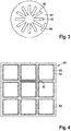
- the element body of the treatment element 41 may comprise, instead of the channel structure, louvers also arranged in the flow path, as for example in the cross-sectional view of FIG FIG. 3 illustrated, star-shaped blades 42, their outer surfaces extend parallel to the flow path and are wholly or partially formed as Beduftungsdon 43.
- the surfaces may be provided with a fragrance or contain encapsulated fragrances.
- the passage openings 42 of the treatment element 41 may have a honeycomb structure, a circular cross-section or another cross-sectional surface shape in cross-section.
- the conditioning element 41 may have a length in the flow direction of between 1 to 10 cm.
- FIG. 4 shows as an example a cross-sectional view of another treatment element 51, which is designed as a multi-component injection-molded plastic element. It has an element core 52, which is formed from a first plastic material which is not or only partially provided with fragrances.
- the element core 52 has passage openings 53, which in the present exemplary embodiment have a square cross section, but are not limited to this shape of the cross section. Thus, other cross-sectional shapes can be provided and appropriate.
- the surfaces in the passage openings 53 are provided with a coating 54 or layer with a second plastic material.
- the second plastic material is provided with perfumes in one of the above-described ways, wherein at least one of the perfumes is provided only in the second plastic material. Thereby, the at least one perfume can be placed close to the surface, whereby the efficiency of the use of the at least one perfume can be improved.
- the element body of the treatment element 41 may be made of a material which is formed mainly of a plastic, such as PP, PES, PA and the like.
- the air treatment element 41 is provided in particular on its surfaces with one or more fragrances that can be delivered to the flowing air flow.
- the fragrance or substances can be introduced as encapsulated fragrances in the polymer matrix of the relevant plastic of the element body. The perfumes are released from it over time to the air flow and carried with this in the interior 5.
- fragrances used are commercial "aromatic" substances which are encapsulated in the material structure of the element during the manufacturing process of the element body in a shaping process (for example injection molding, extrusion or fiber spinning).
- fragrances e.g. Coumarin, benzylidene heptanal, limonene, eugenol, 2-phenylethylalcohol, heliotropin, vanillin, muscone and maltol.
- the uniform distribution of the fragrances encapsulated in a polymer matrix in the element body is determined by the production process, here in particular the injection molding process or extrusion process in the case of a honeycomb body, or the fiber spinning process in the case of a nonwoven fabric element.
- the discharge of perfume (s) from the surfaces of the passageways 42 or from the material of the treatment element 41 may be controlled by a controllable heater 44, thereby increasing the concentration of perfumes at higher temperatures.
- the heating device 44 may preferably be designed as an electrical heating device, which may in particular be temperature-controlled.
- the heater 44 may be provided on the edge of the element body or in the center of the element body preferably extending over the length of the element body.
- the treatment element 41 By forming the treatment element 41 with a plurality of individual passage openings 42, the area along which the air flow passes along the air conditioning air can be considerably increased, so that the absorption of fragrances from the element body is facilitated.
- a flow rectification is also effected by reducing turbulences in the air flow and laminating the air flow emerging on the output side of the air treatment device 4. This reduces the flow noise on the output side of the processing device 4.
- FIG. 4 shows as an example a cross-sectional view of another treatment element 51, which is designed as a multi-component injection-molded plastic element or multi-component extrusion element. It has an element core 52 which is formed of a first plastic material which is not provided with fragrances. The element core 52 has passage openings 53. The passage openings 53 are provided in the present embodiment with a rectangular cross-section. Other cross sections of the through openings 53 for the multi-component plastic element can be provided.
- the surfaces in the passage openings 53 are provided with a coating 54 or layer with a second plastic material.
- the second plastic material is provided with fragrance in one of the ways described above. As a result, the fragrances can be placed close to the surface, which can improve the efficiency of the use of fragrances.
- a heater 55 may be embedded as described above.
- FIG. 5 shows as an example a cross-sectional view of another treatment element 61 formed as a multi-component nonwoven fabric element.
- the multi-component nonwoven fabric member 61 is made of fibers 62 having an element core 63 made of a first plastic material is formed, which is not or only partially provided with fragrances.
- the second plastic material 64 is shown in the cross-sectional view of the fiber as an outer jacket completely surrounding the fibers 62. Alternatively, the second plastic material may only partially, ie not completely, cover the fibers 62.
- the fragrancing surfaces in the through-holes 65 correspond to the surfaces covered by the second plastic material 64 or the surfaces of the element core 63 that are coated with the second plastic material.
- the second plastic material 64 is provided with perfumes in one of the ways described above. As a result, the fragrances can be placed close to the surface, which can improve the efficiency of the use of fragrances.
- the passage openings 65 of the treatment element 61 may be inhomogeneous and variable in cross-section and correspond to the free spaces between the fibers.
- the treatment element 61 may have a length in the flow direction of between 1 to 5 cm.
- the multi-component nonwoven fabric element may consist of one or more plastics of the material classes PP, PES, PET, PA, PBT, wherein the first and the second plastic material may differ only in their physical properties, such as temperature resistance, melting point or softening point.
Landscapes
- Engineering & Computer Science (AREA)
- Mechanical Engineering (AREA)
- Chemical & Material Sciences (AREA)
- Health & Medical Sciences (AREA)
- Combustion & Propulsion (AREA)
- General Engineering & Computer Science (AREA)
- Life Sciences & Earth Sciences (AREA)
- Epidemiology (AREA)
- Animal Behavior & Ethology (AREA)
- General Health & Medical Sciences (AREA)
- Public Health (AREA)
- Veterinary Medicine (AREA)
- Chemical Kinetics & Catalysis (AREA)
- Dispersion Chemistry (AREA)
- Disinfection, Sterilisation Or Deodorisation Of Air (AREA)
- Air-Conditioning For Vehicles (AREA)
Abstract
Description
- Die Erfindung betrifft Luftaufbereitungseinrichtungen zur Anordnung in einer Luftströmung zur Klimatisierung eines Innenraums, insbesondere eines Innenraums einer mobilen Einrichtung, wie z.B. einem Kraftfahrzeug.
- Luftaufbereitungseinrichtungen können dazu dienen, Klimatisierungsluft mit einem Duft zu versehen, bevor diese in einen Innenraum geführt wird. Oft ist eine derartige Luftaufbereitungseinrichtung mit einem mit Duftstoff getränkten Vliesstoff ausgebildet, der im Strömungspfad angeordnet ist. Ein Lüfter fördert dabei den Luftstrom durch den Vliesstoff in Richtung des Innenraumes.
- Die Kapazität eines mit Duftstoffen getränkten Vliesstoffes ist sehr eingeschränkt, so dass die Duftwirkung nur kurz andauern kann. Auch ist eine Regelung der Beduftungsintensität mit diesem System nicht möglich. So nimmt die Beduftungswirkung über die Zeit erheblich ab.
- Außerdem stellen derartige Luftaufbereitungseinrichtungen einen Strömungswiderstand dar, durch den die Strömungsstärke des Luftstroms reduziert wird und wodurch für einen vorgegebenen Klimatisierungsluftstrom eine erhöhte elektrische Lüfterleistung benötigt wird. Diese führt jedoch zu einer zusätzlichen Geräuschentwicklung, das störend im Innenraum wahrgenommen werden kann.
- Weiterhin sind mit granularen Duftstoffen gefüllte Duftkartuschen bekannt, die im Strömungsbereich in den Luftführungskanälen oder in den Faltungen eines Luftfilters angeordnet sind. Diese Duftkartuschen stören die Luftführung, erzeugen ungewünschte Luftturbulenzen und können ebenfalls erhöhte Strömungsgeräusche verursachen.
- Allgemein wird das Vorsehen einer Beduftung der Klimatisierungsluft mit einer zusätzlichen Luftaufbereitungseinrichtung erreicht, das einen zusätzlichen Platzbedarf im Klimatisierungssystem erfordert und einen zusätzlichen Aufwand bei der Montage darstellt.
- Es ist daher Aufgabe der vorliegenden Erfindung, eine verbesserte Möglichkeit bereitzustellen, in einem Klimatisierungssystem die in einen Innenraum zugeführte Klimatisierungsluft mit Duftstoffen anzureichern.
- Diese Aufgabe wird durch die Luftaufbereitungseinrichtung für ein Klimatisierungssystem gemäß Anspruch 1 sowie das Klimatisierungssystem gemäß dem nebengeordneten Anspruch gelöst.
- Weitere Ausgestaltungen sind in den abhängigen Ansprüchen angegeben.
- Gemäß einem ersten Aspekt ist eine Luftaufbereitungseinrichtung für eine Luftströmung eines Klimatisierungssystems vorgesehen, umfassend ein Luftaufbereitungselement mit einer oder mehreren sich in einer Strömungsrichtung einer Klimatisierungsluft erstreckenden Durchgangsöffnungen, wobei die Durchgangsöffnungen in Strömungsrichtung verlaufende Beduftungsflächen aufweisen, die ausgebildet sind, einen oder mehrere Duftstoffe an eine durchströmende Luftströmung abzugeben.
- Eine Idee der obigen Luftaufbereitungseinrichtung besteht darin, die Funktion der Strömungsgleichrichtung, des Beduftens, einer Ozon-Reduktion und einer geräuschmindernden Wirkung gleichzeitig zu erreichen. Dabei stellt die Luftaufbereitungseinrichtung ein in ein Klimatisierungssystem einzusetzendes Bauteil mit im Wesentlichen einem einzelnen Element dar, durch das die Klimatisierungsluft aufbereitet werden kann. Die Luftaufbereitungseinrichtung weist dazu im Wesentlichen ein Luftaufbereitungselement mit entlang der Strömungsrichtung verlaufenden Beduftungsflächen auf, die mit einem Duftstoff angereichert sind, so dass bei Durchströmen der Klimatisierungsluft diese mit dem Duftstoff angereichert wird.
- Durch das Vorsehen eines möglichst großen Flächenanteils, an dem die Luftströmung entlangströmt, können stromaufwärts erzeugte Geräusche, wie beispielsweise ein Lüftergeräusch, durch eine große Anzahl von Schallreflexionsflächen gebrochen werden, so dass eine erhebliche Geräuschreduzierung erreicht werden kann, ohne dass zusätzliche Geräusche durch das Entlangströmen der Klimatisierungsluft entlang der Beduftungsflächen erzeugt werden. Weiterhin kann die Luftströmung durch eine parallele Anordnung der Beduftungsflächen entlang deren Verlaufs gleichgerichtet werden, um so beim Eintritt der Klimatisierungsluft in den Innenraum einen laminareren Strömungsverlauf zu erreichen. Auch besteht bei einer solchen Anordnung der Beduftungsflächen ein geringerer Strömungswiderstand, der wiederum zu einer geringeren Geräuschentwicklung in dem Klimatisierungssystem führt. Zudem wird erreicht, dass aufgrund der großen Fläche, an der die Klimatisierungsluft entlangströmt, das in der Klimatisierungsluft befindliche Ozon reduziert wird.
- Somit kann durch die Luftaufbereitungseinrichtung eine Strömungsgleichrichtung, eine Beduftungsfunktion, eine Ozonreduktion und eine geräuschmindernde Wirkung mit einem gemeinsamen Bauelement erreicht werden.
- Gemäß einer Ausführungsform kann das Aufbereitungselement einen Vliesstoff, insbesondere einen Spinnvliesstoff oder einen Stapelfaservliesstoff, aufweisen und mindestens einer der Duftstoffe in Fasern des Vliesstoffes eingebettet sein.
- Weiterhin kann das Aufbereitungselement einen Mehrkomponenten-Vliesstoff, insbesondere einen Spinnvliesstoff oder einen Stapelfaservliesstoff, aufweisen, wobei der Mehrkomponenten-Vliesstoff Fasern aufweist, die einen Kernbereich und einen den Kernbereich umgebenden Außenbereich aufweisen. Der Kernbereich und der Außenbereich unterscheiden sich in ihren chemischen und/oder physikalischen Eigenschaften. Mindestens einer der Duftstoffe ist ausschließlich in dem Außenbereich der Fasern des Vliesstoffes eingebettet.
- Weiterhin können die Durchgangsöffnungen des Aufbereitungselements einen wabenförmigen, kreisförmigen, ovalen, rechteckigen und mehreckigen Querschnitt aufweisen.
- Es kann vorgesehen sein, dass das Aufbereitungselement einen Querschnitt aufweist, der durch flächige Lamellen ausgebildet ist und insbesondere einen sternförmigen Querschnitt aufweist.
- Gemäß einer Ausführungsform kann das Aufbereitungselement aus einem Kunststoff ausgebildet sein, wobei mindestens einer der Duftstoffe als verkapselter Duftstoff in eine Polymermatrix des betreffenden Kunststoffs des Elementkörpers des Aufbereitungselements eingebracht ist.
- Gemäß einer weiteren Ausführungsform kann das Luftaufbereitungselement mit einem Mehrkomponenten-Kunststoff ausgebildet sein, wobei mindestens einer der Duftstoffe als verkapselter Duftstoff in eine Polymermatrix des ersten Kunststoffes des Elementkörpers des Luftaufbereitungselements eingebracht ist, wobei der erste Kunststoff gezielt an der Oberfläche der Beduftungsflächen des Luftaufbereitungselements angeordnet ist und mindestens ein zweiter Kunststoff (d.h. z.B. ein anderes Kunststoffmaterial, eine andere Materialstruktur oder dergleichen) im Kern des Aufbereitungselements angebracht ist. Durch die oberflächennahe Anordnung des Duftstoffes wird die Abgabe an den Luftstrom verbessert und die Menge des verwendeten Duftstoffes kann reduziert werden.
- Es kann vorgesehen sein, dass das Luftaufbereitungselement mit einer Heizeinrichtung versehen ist, um durch Erwärmen des Aufbereitungselements die Rate der Abgabe des einen oder der mehreren Duftstoffe zu steuern.
- Insbesondere kann die Konzentration des in den Luftstrom abgegebenen Duftstoffes durch die Partialdruckdifferenz/Konzentration der Duftstoffe innerhalb des Elementes gegenüber der umgebenden Atmosphäre und dem Temperaturgradient zwischen Element und Umgebung erreicht werden.
- Ausführungsformen werden nachfolgend anhand der beigefügten Zeichnungen näher erläutert. Es zeigen:
- Figur 1
- eine schematische Darstellung eines Klimatisierungssystems für einen Innenraum; und
- Figuren 2a und 2b
- eine detailliertere Darstellung einer möglichen Ausführungsform einer Aufbereitungseinrichtung in einer Seitenansicht und in einer Querschnittsansicht;
- Figur 3
- eine detaillierte Darstellung einer Querschnittsansicht einer weiteren Aufbereitungseinrichtung;
- Figur 4
- eine Querschnittsansicht eines weiteren Aufbereitungselements; und
- Figuren 5a und 5b
- eine Querschnittsansicht eines Vliesstoffes als Aufbereitungselement und einer vergrößerten Abbildung eines Schnittes durch den Vliesstoff.
-
Figur 1 zeigt schematisch ein Klimatisierungssystem 1 für einen Innenraum, z. B. einen Innenraum eines Kraftfahrzeugs oder dergleichen. Das Klimatisierungssystem 1 umfasst einen Lüfter 2, um Frischluft aus der Umgebung anzusaugen und eine Luftströmung bereitzustellen, die anschließend durch einen Wärmetauscher 3 zum Kühlen oder Erwärmen der Klimatisierungsluft geführt wird. - Stromabwärts des Wärmetauschers 3 ist eine Luftaufbereitungseinrichtung 4 in der Luftströmung vor dem Eintritt der Luftströmung in den Innenraum 5 angeordnet. Insbesondere ist die Luftaufbereitungseinrichtung 4 unmittelbar an einem Luftauslass 6 oder möglichst nah an dem Luftauslass 6 in dem Innenraum 5 angeordnet und kann austauschbar in der Luftströmung angeordnet sein.
- Die
Figuren 2a und 2b zeigen verschiedene Ansichten einer beispielhaften Luftaufbereitungseinrichtung 4. InFigur 2a ist eine Schnittansicht entlang der Längsrichtung L gezeigt, die der Strömungsrichtung der Klimatisierungsluft entspricht.Figur 2b zeigt eine entsprechende Querschnittsansicht.Figur 2a zeigt die Luftaufbereitungseinrichtung 4 mit einem Aufbereitungselement 41, das in einem Strömungspfad 7 des Klimatisierungssystems 1 angeordnet ist. Das Aufbereitungselement 41 weist eine Vielzahl von sich entlang des Strömungspfades 7 erstreckenden Durchgangsöffnungen 42 auf, deren Innenflächen im Wesentlichen parallel zueinander verlaufen. Die Innenflächen der Durchgangsöffnungen 42 können ganz oder teilweise als Beduftungsflächen 43 ausgebildet sein. - Der Elementkörper des Aufbereitungselements 41 kann anstelle der Kanalstruktur auch im Strömungspfad angeordnete Lamellen umfassen, wie beispielsweise in der Querschnittsansicht der
Figur 3 dargestellt, sternförmig angeordnete Lamellen 42, deren Außenflächen sich parallel zum Strömungspfad erstrecken und ganz oder teilweise als Beduftungsflächen 43 ausgebildet sind. - Im Bereich der Beduftungsflächen 43 können die Oberflächen mit einem Duftstoff beaufschlagt sein oder verkapselte Duftstoffe beinhalten.
- Die Durchgangsöffnungen 42 des Aufbereitungselements 41 können im Querschnitt eine Wabenstruktur, einen kreisförmigen Querschnitt oder eine sonstige Querschnittsflächenform aufweisen. Das Aufbereitungselement 41 kann eine Länge in Strömungsrichtung von zwischen 1 bis 10 cm aufweisen. Insbesondere kann das Verhältnis aus Querschnittsfläche Q [cm2] und der Länge L[cm] des Aufbereitungselements 41 L/Q = 0,1 oder weniger betragen.
- Die
Figur 4 zeigt als ein Beispiel eine Querschnittsansicht eines weiteren Aufbereitungselements 51, das als ein Mehrkomponenten-Spritzguss Kunststoffelement ausgebildet ist. Es weist einen Elementkern 52 auf, der aus einem ersten Kunststoffmaterial ausgebildet ist, der nicht oder nur teilweise mit Duftstoffen versehen ist. Der Elementkern 52 weist Durchgangsöffnungen 53 auf, die im vorliegenden Ausführungsbeispiel einen quadratischen Querschnitt aufweisen, aber nicht auf diese Form des Querschnittes beschränkt sind. So können auch andere Querschnittsformen vorgesehen und zweckmäßig sein. - Die Oberflächen in den Durchgangsöffnungen 53 sind mit einer Beschichtung 54 oder Lage mit einem zweiten Kunststoffmaterial versehen. Das zweite Kunststoffmaterial ist in einer der oben beschriebenen Arten mit Duftstoffen versehen, wobei mindestens einer der Duftstoffe nur in dem zweiten Kunststoffmaterial vorgesehen ist. Dadurch kann der mindestens eine Duftstoff nahe an der Oberfläche platziert werden, wodurch die Effizienz des Einsatzes des mindestens einen Duftstoffes verbessert werden kann.
- Der Elementkörper des Aufbereitungselements 41 kann aus einem Material hergestellt sein, das mehrheitlich aus einem Kunststoff, wie zum Beispiel PP, PES, PA und dergleichen ausgebildet ist. Das Luftaufbereitungselement 41 ist insbesondere an dessen Oberflächen mit einem oder mehreren Duftstoffen versehen, der an die durchströmende Luftströmung abgegeben werden kann. Dazu kann der bzw. die Duftstoffe als verkapselte Duftstoffe in die Polymermatrix des betreffenden Kunststoffs des Elementkörpers eingebracht werden. Die Duftstoffe werden daraus über die Zeit an die Luftströmung abgegeben und mit dieser in den Innenraum 5 getragen.
- Als Duftstoffe kommen handelsübliche "aromatische" Substanzen zum Einsatz, die während des Herstellungsprozesses des Elementkörpers in einem Formgebungsprozess (z.B. Spritzguss, Extrusion oder Faserspinnen) verkapselt in die Materialstruktur des Elementes eingebracht wird. Als Duftstoffe können z.B. Cumarin, Benzylidenheptanal, Limone, Eugenol, 2-Phenyläthylalkohol, Heliotropin, Vanillin, Muscon und Maltol verwendet werden.
- Die gleichmäßige Verteilung der in einer Polymermatrix verkapselten Duftstoffe im Elementkörper wird durch den Herstellungsprozess, hier insbesondere den Spritzgussprozess oder Extrusionsprozess im Falle eines Wabenkörpers oder den Faserspinnprozess im Falle eines Vliesstoffelementes bestimmt.
- Der Austrag des bzw. der Duftstoffe von den Oberflächen der Durchgangsöffnungen 42 oder aus dem Material des Aufbereitungselements 41 kann durch eine steuerbare Heizeinrichtung 44 gesteuert werden, wobei die Konzentration der Duftstoffe bei höheren Temperaturen erhöht wird. Die Heizeinrichtung 44 kann vorzugsweise als elektrische Heizeinrichtung ausgebildet sein, die insbesondere temperaturgeregelt sein kann. Die Heizeinrichtung 44 kann am Rand des Elementkörpers oder mittig des Elementkörpers vorzugsweise sich über die Länge des Elementkörpers erstreckend vorgesehen sein.
- Durch die Ausbildung des Aufbereitungselements 41 mit einer Vielzahl von einzelnen Durchgangsöffnungen 42 kann die Fläche, an der die Luftströmung der Klimatisierungsluft entlangstreicht, erheblich vergrößert werden, so dass die Aufnahme von Duftstoffen aus dem Elementkörper erleichtert wird.
- Weiterhin führt eine große Oberfläche, an der die Luftströmung entlangströmt, zu einer Reduzierung von in der durchströmenden Klimatisierungsluft enthaltenen Ozon, das in der Regel durch Kontakt an beliebigen Oberflächen reduziert wird.
- Auch erfolgt eine Strömungsgleichrichtung, indem Turbulenzen in dem Luftstrom reduziert werden und die ausgangsseitig der Luftaufbereitungseinrichtung 4 austretende Luftströmung laminarisiert ist. Dies reduziert die Strömungsgeräusche ausgangsseitig der Aufbereitungseinrichtung 4.
-
Figur 4 zeigt als ein Beispiel eine Querschnittsansicht eines weiteren Aufbereitungselements 51, das als ein Mehrkomponenten-Spritzguss Kunststoffelement oder Mehrkomponenten-Extrusionselement ausgebildet ist. Es weist einen Elementkern 52 auf, der aus einem ersten Kunststoffmaterial ausgebildet ist, der nicht mit Duftstoffen versehen ist. Der Elementkern 52 weist Durchgangsöffnungen 53 auf. Die Durchgangsöffnungen 53 sind im vorliegenden Ausführungsbeispiel mit einem rechteckigen Querschnitt versehen. Auch andere Querschnitte der Durchgangsöffnungen 53 für das Mehrkomponenten-Kunststoffelement können vorgesehen werden. - Die Oberflächen in den Durchgangsöffnungen 53 sind mit einer Beschichtung 54 oder Lage mit einem zweiten Kunststoffmaterial versehen. Das zweite Kunststoffmaterial ist in einer der oben beschriebenen Arten mit Duftstoffen versehen. Dadurch können die Duftstoffe nahe an der Oberfläche platziert werden können, wodurch die Effizienz des Einsatzes von Duftstoffen verbessert werden kann.
- In dem Elementkern 52 kann eine Heizeinrichtung 55, wie oben beschrieben, eingebettet sein.
-
Figur 5 zeigt als ein Beispiel eine Querschnittsansicht eines weiteren Aufbereitungselements 61, das als ein Mehrkomponenten-Vliesstoffelement ausgebildet ist. Das Mehrkomponenten-Vliesstoffelement 61 besteht aus Fasern 62, welche einen Elementkern 63 aufweisen, der aus einem ersten Kunststoffmaterial ausgebildet ist, der nicht oder nur teilweise mit Duftstoffen versehen ist. Das zweite Kunststoffmaterial 64 ist in der Querschnittsansicht der Faser als äußerer Mantel dargestellt, der die Fasern 62 vollständig umgibt. Alternativ kann das zweite Kunststoffmaterial die Fasern 62 nur teilweise, d.h. nicht vollumfänglich bedecken. Die Beduftungsflächen in den Durchgangsöffnungen 65 entsprechen den durch das zweite Kunststoffmaterial 64 bedeckten Flächen bzw. der Flächen des Elementkerns 63, die mit dem zweiten Kunststoffmaterial beschichtet sind. Das zweite Kunststoffmaterial 64 ist in einer der oben beschriebenen Arten mit Duftstoffen versehen. Dadurch können die Duftstoffe nahe an der Oberfläche platziert werden, wodurch die Effizienz des Einsatzes von Duftstoffen verbessert werden kann. - Die Durchgangsöffnungen 65 des Aufbereitungselements 61 können im Querschnitt inhomogen und variabel angeordnet sein und entsprechen den freien Zwischenräumen zwischen den Fasern. Das Aufbereitungselement 61 kann eine Länge in Strömungsrichtung von zwischen 1 bis 5 cm aufweisen. Insbesondere kann das Verhältnis aus Querschnittsfläche Q [cm2] und der Länge L[cm] des Aufbereitungselements 61 L/Q = 0,05 oder weniger betragen.
- Das Mehrkomponenten-Vliesstoffelement kann aus einem oder mehreren Kunststoffen der Materialklassen PP, PES, PET, PA, PBT bestehen, wobei das erste und das zweite Kunststoffmaterial sich auch nur in ihren physikalischen Eigenschaften, wie z.B. Temperaturbeständigkeit, Schmelzpunkt oder Erweichungspunkt unterscheiden können.
-
- 1
- Klimatisierungssystem
- 2
- Lüfter
- 3
- Wärmetauscher
- 4
- Luftaufbereitungseinrichtung
- 5
- Innenraum
- 6
- Luftauslass
- 41
- Aufbereitungselement
- 42
- Durchgangsöffnungen
- 43
- Beduftungsflächen
- 44
- steuerbare Heizeinrichtung
- 51
- Aufbereitungselement
- 52
- Elementkern
- 53
- Durchgangsöffnungen
- 54
- Beschichtung
- 55
- Heizeinrichtung
- 61
- Aufbereitungselement
- 62
- Fasern
- 63
- Faserkern
- 64
- Faseraußenbereich
- 65
- Durchgangsöffnungen
- 7
- Strömungspfad
Claims (10)
- Luftaufbereitungseinrichtung (4) für eine Luftströmung eines Klimatisierungssystems (1), umfassend ein Aufbereitungselement (41, 51) mit einer oder mehreren sich teilweise oder vollständig in einer Strömungsrichtung erstreckenden Durchgangsöffnungen (42, 53, 65), wobei die Durchgangsöffnungen (42, 53, 65) in Strömungsrichtung verlaufende Beduftungsflächen (43) aufweisen, die ausgebildet sind, einen oder mehrere Duftstoffe an eine durchströmende Luftströmung abzugeben.
- Luftaufbereitungseinrichtung (4) nach Anspruch 1, wobei das Aufbereitungselement (41, 51) einen Vliesstoff, insbesondere einen Spinnvliesstoff oder einen Stapelfaservliesstoff, aufweist und mindestens einer der Duftstoffe in den Fasern des Vliesstoffes eingebettet ist.
- Luftaufbereitungseinrichtung (4) nach einem der Ansprüche 1 bis 2, wobei das Aufbereitungselement (41, 51) einen Mehrkomponenten-Vliesstoff, insbesondere einen Spinnvliesstoff oder einen Stapelfaservliesstoff, aufweist, wobei der Mehrkomponenten-Vliesstoff Fasern aufweist, welche einen Kernbereich und einen den Kernbereich umgebenden Außenbereich aufweisen, welche sich in ihren chemischen und/oder physikalischen Eigenschaften unterscheiden und wobei mindestens einer der Duftstoffe ausschließlich in den Außenbereich der Fasern des Vliesstoffes eingebettet ist.
- Luftaufbereitungseinrichtung (4) nach Anspruch 1, wobei die Durchgangsöffnungen (42, 53) des Aufbereitungselements (41) jeweils einen wabenförmigen, kreisförmigen, ovalen, und mehreckigen Querschnitt aufweisen.
- Luftaufbereitungseinrichtung (4) nach Anspruch 1, wobei das Aufbereitungselement (41) einen Querschnitt aufweist, der durch flächige Lamellen ausgebildet ist und insbesondere einen sternförmigen Querschnitt aufweist.
- Luftaufbereitungseinrichtung (4) nach einem der Ansprüche 4 bis 5, wobei das Aufbereitungselement (41, 51) aus einem Kunststoff ausgebildet ist, mindestens einer der Duftstoffe als verkapselter Duftstoff in eine Polymermatrix des betreffenden Kunststoffs des Elementkörpers des Aufbereitungselements (41, 51) eingebracht ist.
- Luftaufbereitungseinrichtung (4) nach einem der Ansprüche 4 bis 5, wobei das Aufbereitungselement (51, 61) mit einem Mehrkomponenten-Kunststoff ausgebildet ist und mindestens einer der Duftstoffe als verkapselter Duftstoff in eine Polymermatrix eines ersten Kunststoffs des Elementkörpers des Aufbereitungselements (51, 61) eingebracht ist, wobei der erste Kunststoff gezielt an der Oberfläche der Beduftungsflächen (43) des Aufbereitungselements (51, 61) angeordnet ist und mindestens ein zweiter Kunststoff im Kern des Aufbereitungselements (41, 51) angebracht ist.
- Luftaufbereitungseinrichtung (4) nach einem der Ansprüche 1 bis 7, wobei das Aufbereitungselement (41, 51, 61) mit einer Heizeinrichtung (44, 55) versehen ist, um durch Erwärmen des Aufbereitungselements (41, 51, 61) die Rate der Abgabe des einen oder der mehreren Duftstoffe zu steuern.
- Klimatisierungssystem (1) für einen Innenraum, insbesondere einen Innenraum eines Kraftfahrzeuges, mit einer Luftaufbereitungseinrichtung (4) nach einem der Ansprüche 1 bis 8, die in einer Luftströmung des Klimatisierungssystems (1) angeordnet ist.
- Klimatisierungssystem (1) nach Anspruch 9, wobei das Klimatisierungssystem (1) einen Luftauslass (6) aufweist, wobei die Luftaufbereitungseinrichtung (4) stromaufwärts des Luftauslasses (6) angeordnet ist und insbesondere austauschbar gehalten ist.
Priority Applications (4)
| Application Number | Priority Date | Filing Date | Title |
|---|---|---|---|
| EP17177848.3A EP3421895B1 (de) | 2017-06-26 | 2017-06-26 | Luftaufbereitungseinrichtung zum einsatz in einem luftströmungspfad eines klimatisierungssystems in einer mobilen einrichtung |
| US15/905,869 US20180370333A1 (en) | 2017-06-26 | 2018-02-27 | Air conditioning device for use in an air flow path of an air conditioning system in a mobile device |
| CN201810202341.5A CN109109623A (zh) | 2017-06-26 | 2018-03-13 | 用于可移动设备中的空调系统的空气流路径中的空气处理装置 |
| KR1020180038719A KR102161660B1 (ko) | 2017-06-26 | 2018-04-03 | 이동식 장치용 공기 조화 시스템의 공기 유동 경로 내에 사용하기 위한 공기 조화 장치 |
Applications Claiming Priority (1)
| Application Number | Priority Date | Filing Date | Title |
|---|---|---|---|
| EP17177848.3A EP3421895B1 (de) | 2017-06-26 | 2017-06-26 | Luftaufbereitungseinrichtung zum einsatz in einem luftströmungspfad eines klimatisierungssystems in einer mobilen einrichtung |
Publications (2)
| Publication Number | Publication Date |
|---|---|
| EP3421895A1 true EP3421895A1 (de) | 2019-01-02 |
| EP3421895B1 EP3421895B1 (de) | 2020-11-18 |
Family
ID=59337430
Family Applications (1)
| Application Number | Title | Priority Date | Filing Date |
|---|---|---|---|
| EP17177848.3A Not-in-force EP3421895B1 (de) | 2017-06-26 | 2017-06-26 | Luftaufbereitungseinrichtung zum einsatz in einem luftströmungspfad eines klimatisierungssystems in einer mobilen einrichtung |
Country Status (4)
| Country | Link |
|---|---|
| US (1) | US20180370333A1 (de) |
| EP (1) | EP3421895B1 (de) |
| KR (1) | KR102161660B1 (de) |
| CN (1) | CN109109623A (de) |
Families Citing this family (2)
| Publication number | Priority date | Publication date | Assignee | Title |
|---|---|---|---|---|
| CN115431717A (zh) * | 2022-09-29 | 2022-12-06 | 东风汽车集团股份有限公司 | 一种车载香氛系统及车辆 |
| DE102024108516A1 (de) * | 2024-03-26 | 2025-10-02 | Audi Aktiengesellschaft | Beduftungseinrichtung für ein Kraftfahrzeug, Verfahren zum Herstellen einer Beduftungseinrichtung, Verfahren zum Betreiben einer Beduftungseinrichtung sowie Verwendung eines Kunststoffbauteils |
Citations (6)
| Publication number | Priority date | Publication date | Assignee | Title |
|---|---|---|---|---|
| EP0645148A1 (de) * | 1993-09-23 | 1995-03-29 | Dudley Industries Ltd. | Photoelektrische Luftbehandlungsvorrichtung |
| EP0720925A1 (de) * | 1995-01-09 | 1996-07-10 | Supair AG | Luftauffrischer, insbesondere für Fahrzeuge |
| US20060005711A1 (en) * | 2004-07-07 | 2006-01-12 | Andrew Olefson | Replaceable filter for a vehicle air conditioning system adapted to scent air |
| DE102007044978A1 (de) * | 2007-09-19 | 2009-04-02 | Behr Gmbh & Co. Kg | Verfahren und Vorrichtung zur Beduftung von Innenräumen |
| DE102009058111A1 (de) * | 2009-12-12 | 2010-07-29 | Daimler Ag | Luftauslass für eine Belüftungseinrichtung eines Kraftfahrzeugs und Belüftungseinrichtung |
| DE102013015649A1 (de) * | 2013-09-23 | 2015-03-26 | Mann + Hummel Gmbh | Innenraumfilter und Filteranordnung |
Family Cites Families (8)
| Publication number | Priority date | Publication date | Assignee | Title |
|---|---|---|---|---|
| JP3634234B2 (ja) | 2000-04-24 | 2005-03-30 | 五洋建設株式会社 | 脱臭装置 |
| JP2004337035A (ja) * | 2003-05-14 | 2004-12-02 | Fumakilla Ltd | 薬剤放散装置 |
| GB2417204A (en) | 2004-08-19 | 2006-02-22 | Bell Flavours & Fragrances Ltd | Air treatment apparatus |
| US8851396B2 (en) * | 2009-01-27 | 2014-10-07 | American Covers, Inc. | Dual scent air freshener with manual combiner |
| EP2450205B1 (de) * | 2009-07-01 | 2014-03-26 | Nissan Motor Co., Ltd. | Duftlufterfrischer für fahrzeuge und verfahren zum ausblasen parfümierter luft dafür |
| CN103037907A (zh) * | 2010-03-31 | 2013-04-10 | 境味股份有限公司 | 用于嗅觉活性物质的方法、组合物和制品 |
| CN106132368B (zh) * | 2014-04-10 | 2018-09-21 | 3M创新有限公司 | 纤维和包含纤维的制品 |
| CN205768519U (zh) * | 2016-06-01 | 2016-12-07 | 谢萍萍 | 一种具有芳香气味的汽车空调滤清器 |
-
2017
- 2017-06-26 EP EP17177848.3A patent/EP3421895B1/de not_active Not-in-force
-
2018
- 2018-02-27 US US15/905,869 patent/US20180370333A1/en not_active Abandoned
- 2018-03-13 CN CN201810202341.5A patent/CN109109623A/zh active Pending
- 2018-04-03 KR KR1020180038719A patent/KR102161660B1/ko not_active Expired - Fee Related
Patent Citations (6)
| Publication number | Priority date | Publication date | Assignee | Title |
|---|---|---|---|---|
| EP0645148A1 (de) * | 1993-09-23 | 1995-03-29 | Dudley Industries Ltd. | Photoelektrische Luftbehandlungsvorrichtung |
| EP0720925A1 (de) * | 1995-01-09 | 1996-07-10 | Supair AG | Luftauffrischer, insbesondere für Fahrzeuge |
| US20060005711A1 (en) * | 2004-07-07 | 2006-01-12 | Andrew Olefson | Replaceable filter for a vehicle air conditioning system adapted to scent air |
| DE102007044978A1 (de) * | 2007-09-19 | 2009-04-02 | Behr Gmbh & Co. Kg | Verfahren und Vorrichtung zur Beduftung von Innenräumen |
| DE102009058111A1 (de) * | 2009-12-12 | 2010-07-29 | Daimler Ag | Luftauslass für eine Belüftungseinrichtung eines Kraftfahrzeugs und Belüftungseinrichtung |
| DE102013015649A1 (de) * | 2013-09-23 | 2015-03-26 | Mann + Hummel Gmbh | Innenraumfilter und Filteranordnung |
Also Published As
| Publication number | Publication date |
|---|---|
| KR20190001505A (ko) | 2019-01-04 |
| KR102161660B1 (ko) | 2020-10-05 |
| US20180370333A1 (en) | 2018-12-27 |
| CN109109623A (zh) | 2019-01-01 |
| EP3421895B1 (de) | 2020-11-18 |
Similar Documents
| Publication | Publication Date | Title |
|---|---|---|
| DE102007047415B3 (de) | Flüssigkeitsverdampfer | |
| EP1680304A1 (de) | Baureihe für einen fahrzeugsitz | |
| EP1854647A1 (de) | Beduftungssystem, insbesondere für ein Kraftfahrzeug | |
| DE69725667T2 (de) | Fahrzeugheizgerät | |
| EP3421895B1 (de) | Luftaufbereitungseinrichtung zum einsatz in einem luftströmungspfad eines klimatisierungssystems in einer mobilen einrichtung | |
| EP1907237A1 (de) | Kraftfahrzeugsitz mit einer luftversorgungseinrichtung | |
| DE10121286A1 (de) | Luftführungsgehäuse | |
| DE102010050390A1 (de) | Sitzbelüftungseinrichtung für ein Polster eines Fahrzeugsitzes | |
| DE102009038311A1 (de) | Vorrichtung zur Klimatisierung eines Fahrzeugsitzes, insbesondere eines Flugzeugsitzes | |
| DE202015102766U1 (de) | Defrosterdüse mit Netz über dem Auslass | |
| EP3487719B1 (de) | Lüftungsanlage und kraftfahrzeug | |
| DE102007010796A1 (de) | Anordnung mit einer Beduftungsvorrichtung, insbesondere für ein Kraftfahrzeug | |
| EP1851075B1 (de) | Heizvorrichtung zum erwärmen eines luftstroms insbesondere für ein karftfahrzeug | |
| DE102007013432B4 (de) | Warmluftkanal für ein Klimagerät eines Kraftfahrzeuges | |
| AT523395A4 (de) | Vorrichtung zum Beduften eines Raumes | |
| EP1228916B1 (de) | Instrumententafel für ein Fahrzeug, insbesondere für ein Kraftfahrzeug | |
| DE102005035116B3 (de) | Kraftahrzeugsitz mit einer Belüftungseinrichtung | |
| DE102005035113B4 (de) | Kraftfahrzeugsitz mit einer Luftversorgungseinrichtung | |
| EP3065993B1 (de) | Verfahren zur klimatisierung eines fahrzeugs, insbesondere eines schienenfahrzeugs | |
| DE102021002914A1 (de) | Polster für einen Fahrzeugsitz eines Kraftwagens | |
| DE102005008596B3 (de) | Heizvorrichtung zum Erwärmen eines Luftstroms insbesondere für ein Kraftfahrzeug | |
| DE102005003326B4 (de) | Fahrzeugsitz mit Klimasystem | |
| DE102018204059A1 (de) | Anordnung zum Beheizen eines Fahrzeuginnenraums | |
| DE10346388A1 (de) | Kanalleitvorrichtung zur Bildung zumindest eines Kanals für strömende Medien | |
| EP3072574A1 (de) | Vorrichtung und verfahren zum in-kontakt-bringen eines gases mit einer flüssigkeit |
Legal Events
| Date | Code | Title | Description |
|---|---|---|---|
| PUAI | Public reference made under article 153(3) epc to a published international application that has entered the european phase |
Free format text: ORIGINAL CODE: 0009012 |
|
| STAA | Information on the status of an ep patent application or granted ep patent |
Free format text: STATUS: THE APPLICATION HAS BEEN PUBLISHED |
|
| AK | Designated contracting states |
Kind code of ref document: A1 Designated state(s): AL AT BE BG CH CY CZ DE DK EE ES FI FR GB GR HR HU IE IS IT LI LT LU LV MC MK MT NL NO PL PT RO RS SE SI SK SM TR |
|
| AX | Request for extension of the european patent |
Extension state: BA ME |
|
| STAA | Information on the status of an ep patent application or granted ep patent |
Free format text: STATUS: REQUEST FOR EXAMINATION WAS MADE |
|
| 17P | Request for examination filed |
Effective date: 20190117 |
|
| RBV | Designated contracting states (corrected) |
Designated state(s): AL AT BE BG CH CY CZ DE DK EE ES FI FR GB GR HR HU IE IS IT LI LT LU LV MC MK MT NL NO PL PT RO RS SE SI SK SM TR |
|
| GRAP | Despatch of communication of intention to grant a patent |
Free format text: ORIGINAL CODE: EPIDOSNIGR1 |
|
| STAA | Information on the status of an ep patent application or granted ep patent |
Free format text: STATUS: GRANT OF PATENT IS INTENDED |
|
| RIC1 | Information provided on ipc code assigned before grant |
Ipc: B60H 3/00 20060101ALI20200610BHEP Ipc: F24F 3/16 20060101ALI20200610BHEP Ipc: F24F 3/12 20060101AFI20200610BHEP |
|
| INTG | Intention to grant announced |
Effective date: 20200629 |
|
| GRAS | Grant fee paid |
Free format text: ORIGINAL CODE: EPIDOSNIGR3 |
|
| GRAA | (expected) grant |
Free format text: ORIGINAL CODE: 0009210 |
|
| STAA | Information on the status of an ep patent application or granted ep patent |
Free format text: STATUS: THE PATENT HAS BEEN GRANTED |
|
| AK | Designated contracting states |
Kind code of ref document: B1 Designated state(s): AL AT BE BG CH CY CZ DE DK EE ES FI FR GB GR HR HU IE IS IT LI LT LU LV MC MK MT NL NO PL PT RO RS SE SI SK SM TR |
|
| REG | Reference to a national code |
Ref country code: GB Ref legal event code: FG4D Free format text: NOT ENGLISH |
|
| REG | Reference to a national code |
Ref country code: CH Ref legal event code: EP |
|
| REG | Reference to a national code |
Ref country code: IE Ref legal event code: FG4D Free format text: LANGUAGE OF EP DOCUMENT: GERMAN |
|
| REG | Reference to a national code |
Ref country code: DE Ref legal event code: R096 Ref document number: 502017008227 Country of ref document: DE |
|
| REG | Reference to a national code |
Ref country code: AT Ref legal event code: REF Ref document number: 1336194 Country of ref document: AT Kind code of ref document: T Effective date: 20201215 |
|
| REG | Reference to a national code |
Ref country code: NL Ref legal event code: MP Effective date: 20201118 |
|
| PG25 | Lapsed in a contracting state [announced via postgrant information from national office to epo] |
Ref country code: GR Free format text: LAPSE BECAUSE OF FAILURE TO SUBMIT A TRANSLATION OF THE DESCRIPTION OR TO PAY THE FEE WITHIN THE PRESCRIBED TIME-LIMIT Effective date: 20210219 Ref country code: FI Free format text: LAPSE BECAUSE OF FAILURE TO SUBMIT A TRANSLATION OF THE DESCRIPTION OR TO PAY THE FEE WITHIN THE PRESCRIBED TIME-LIMIT Effective date: 20201118 Ref country code: NO Free format text: LAPSE BECAUSE OF FAILURE TO SUBMIT A TRANSLATION OF THE DESCRIPTION OR TO PAY THE FEE WITHIN THE PRESCRIBED TIME-LIMIT Effective date: 20210218 Ref country code: PT Free format text: LAPSE BECAUSE OF FAILURE TO SUBMIT A TRANSLATION OF THE DESCRIPTION OR TO PAY THE FEE WITHIN THE PRESCRIBED TIME-LIMIT Effective date: 20210318 Ref country code: RS Free format text: LAPSE BECAUSE OF FAILURE TO SUBMIT A TRANSLATION OF THE DESCRIPTION OR TO PAY THE FEE WITHIN THE PRESCRIBED TIME-LIMIT Effective date: 20201118 |
|
| PG25 | Lapsed in a contracting state [announced via postgrant information from national office to epo] |
Ref country code: SE Free format text: LAPSE BECAUSE OF FAILURE TO SUBMIT A TRANSLATION OF THE DESCRIPTION OR TO PAY THE FEE WITHIN THE PRESCRIBED TIME-LIMIT Effective date: 20201118 Ref country code: BG Free format text: LAPSE BECAUSE OF FAILURE TO SUBMIT A TRANSLATION OF THE DESCRIPTION OR TO PAY THE FEE WITHIN THE PRESCRIBED TIME-LIMIT Effective date: 20210218 Ref country code: PL Free format text: LAPSE BECAUSE OF FAILURE TO SUBMIT A TRANSLATION OF THE DESCRIPTION OR TO PAY THE FEE WITHIN THE PRESCRIBED TIME-LIMIT Effective date: 20201118 Ref country code: LV Free format text: LAPSE BECAUSE OF FAILURE TO SUBMIT A TRANSLATION OF THE DESCRIPTION OR TO PAY THE FEE WITHIN THE PRESCRIBED TIME-LIMIT Effective date: 20201118 Ref country code: IS Free format text: LAPSE BECAUSE OF FAILURE TO SUBMIT A TRANSLATION OF THE DESCRIPTION OR TO PAY THE FEE WITHIN THE PRESCRIBED TIME-LIMIT Effective date: 20210318 |
|
| REG | Reference to a national code |
Ref country code: LT Ref legal event code: MG9D |
|
| PG25 | Lapsed in a contracting state [announced via postgrant information from national office to epo] |
Ref country code: HR Free format text: LAPSE BECAUSE OF FAILURE TO SUBMIT A TRANSLATION OF THE DESCRIPTION OR TO PAY THE FEE WITHIN THE PRESCRIBED TIME-LIMIT Effective date: 20201118 |
|
| PG25 | Lapsed in a contracting state [announced via postgrant information from national office to epo] |
Ref country code: SK Free format text: LAPSE BECAUSE OF FAILURE TO SUBMIT A TRANSLATION OF THE DESCRIPTION OR TO PAY THE FEE WITHIN THE PRESCRIBED TIME-LIMIT Effective date: 20201118 Ref country code: RO Free format text: LAPSE BECAUSE OF FAILURE TO SUBMIT A TRANSLATION OF THE DESCRIPTION OR TO PAY THE FEE WITHIN THE PRESCRIBED TIME-LIMIT Effective date: 20201118 Ref country code: CZ Free format text: LAPSE BECAUSE OF FAILURE TO SUBMIT A TRANSLATION OF THE DESCRIPTION OR TO PAY THE FEE WITHIN THE PRESCRIBED TIME-LIMIT Effective date: 20201118 Ref country code: EE Free format text: LAPSE BECAUSE OF FAILURE TO SUBMIT A TRANSLATION OF THE DESCRIPTION OR TO PAY THE FEE WITHIN THE PRESCRIBED TIME-LIMIT Effective date: 20201118 Ref country code: SM Free format text: LAPSE BECAUSE OF FAILURE TO SUBMIT A TRANSLATION OF THE DESCRIPTION OR TO PAY THE FEE WITHIN THE PRESCRIBED TIME-LIMIT Effective date: 20201118 Ref country code: LT Free format text: LAPSE BECAUSE OF FAILURE TO SUBMIT A TRANSLATION OF THE DESCRIPTION OR TO PAY THE FEE WITHIN THE PRESCRIBED TIME-LIMIT Effective date: 20201118 |
|
| REG | Reference to a national code |
Ref country code: DE Ref legal event code: R097 Ref document number: 502017008227 Country of ref document: DE |
|
| PG25 | Lapsed in a contracting state [announced via postgrant information from national office to epo] |
Ref country code: DK Free format text: LAPSE BECAUSE OF FAILURE TO SUBMIT A TRANSLATION OF THE DESCRIPTION OR TO PAY THE FEE WITHIN THE PRESCRIBED TIME-LIMIT Effective date: 20201118 |
|
| PLBE | No opposition filed within time limit |
Free format text: ORIGINAL CODE: 0009261 |
|
| STAA | Information on the status of an ep patent application or granted ep patent |
Free format text: STATUS: NO OPPOSITION FILED WITHIN TIME LIMIT |
|
| 26N | No opposition filed |
Effective date: 20210819 |
|
| PG25 | Lapsed in a contracting state [announced via postgrant information from national office to epo] |
Ref country code: IT Free format text: LAPSE BECAUSE OF FAILURE TO SUBMIT A TRANSLATION OF THE DESCRIPTION OR TO PAY THE FEE WITHIN THE PRESCRIBED TIME-LIMIT Effective date: 20201118 Ref country code: AL Free format text: LAPSE BECAUSE OF FAILURE TO SUBMIT A TRANSLATION OF THE DESCRIPTION OR TO PAY THE FEE WITHIN THE PRESCRIBED TIME-LIMIT Effective date: 20201118 Ref country code: NL Free format text: LAPSE BECAUSE OF FAILURE TO SUBMIT A TRANSLATION OF THE DESCRIPTION OR TO PAY THE FEE WITHIN THE PRESCRIBED TIME-LIMIT Effective date: 20201118 |
|
| PG25 | Lapsed in a contracting state [announced via postgrant information from national office to epo] |
Ref country code: SI Free format text: LAPSE BECAUSE OF FAILURE TO SUBMIT A TRANSLATION OF THE DESCRIPTION OR TO PAY THE FEE WITHIN THE PRESCRIBED TIME-LIMIT Effective date: 20201118 |
|
| REG | Reference to a national code |
Ref country code: DE Ref legal event code: R119 Ref document number: 502017008227 Country of ref document: DE |
|
| PG25 | Lapsed in a contracting state [announced via postgrant information from national office to epo] |
Ref country code: ES Free format text: LAPSE BECAUSE OF FAILURE TO SUBMIT A TRANSLATION OF THE DESCRIPTION OR TO PAY THE FEE WITHIN THE PRESCRIBED TIME-LIMIT Effective date: 20201118 Ref country code: MC Free format text: LAPSE BECAUSE OF FAILURE TO SUBMIT A TRANSLATION OF THE DESCRIPTION OR TO PAY THE FEE WITHIN THE PRESCRIBED TIME-LIMIT Effective date: 20201118 |
|
| REG | Reference to a national code |
Ref country code: CH Ref legal event code: PL |
|
| GBPC | Gb: european patent ceased through non-payment of renewal fee |
Effective date: 20210626 |
|
| REG | Reference to a national code |
Ref country code: BE Ref legal event code: MM Effective date: 20210630 |
|
| PG25 | Lapsed in a contracting state [announced via postgrant information from national office to epo] |
Ref country code: LU Free format text: LAPSE BECAUSE OF NON-PAYMENT OF DUE FEES Effective date: 20210626 |
|
| PG25 | Lapsed in a contracting state [announced via postgrant information from national office to epo] |
Ref country code: LI Free format text: LAPSE BECAUSE OF NON-PAYMENT OF DUE FEES Effective date: 20210630 Ref country code: IE Free format text: LAPSE BECAUSE OF NON-PAYMENT OF DUE FEES Effective date: 20210626 Ref country code: GB Free format text: LAPSE BECAUSE OF NON-PAYMENT OF DUE FEES Effective date: 20210626 Ref country code: DE Free format text: LAPSE BECAUSE OF NON-PAYMENT OF DUE FEES Effective date: 20220101 Ref country code: CH Free format text: LAPSE BECAUSE OF NON-PAYMENT OF DUE FEES Effective date: 20210630 |
|
| PG25 | Lapsed in a contracting state [announced via postgrant information from national office to epo] |
Ref country code: IS Free format text: LAPSE BECAUSE OF FAILURE TO SUBMIT A TRANSLATION OF THE DESCRIPTION OR TO PAY THE FEE WITHIN THE PRESCRIBED TIME-LIMIT Effective date: 20210318 Ref country code: FR Free format text: LAPSE BECAUSE OF NON-PAYMENT OF DUE FEES Effective date: 20210630 |
|
| PG25 | Lapsed in a contracting state [announced via postgrant information from national office to epo] |
Ref country code: BE Free format text: LAPSE BECAUSE OF NON-PAYMENT OF DUE FEES Effective date: 20210630 |
|
| PG25 | Lapsed in a contracting state [announced via postgrant information from national office to epo] |
Ref country code: CY Free format text: LAPSE BECAUSE OF FAILURE TO SUBMIT A TRANSLATION OF THE DESCRIPTION OR TO PAY THE FEE WITHIN THE PRESCRIBED TIME-LIMIT Effective date: 20201118 |
|
| PG25 | Lapsed in a contracting state [announced via postgrant information from national office to epo] |
Ref country code: HU Free format text: LAPSE BECAUSE OF FAILURE TO SUBMIT A TRANSLATION OF THE DESCRIPTION OR TO PAY THE FEE WITHIN THE PRESCRIBED TIME-LIMIT; INVALID AB INITIO Effective date: 20170626 |
|
| REG | Reference to a national code |
Ref country code: AT Ref legal event code: MM01 Ref document number: 1336194 Country of ref document: AT Kind code of ref document: T Effective date: 20220626 |
|
| PG25 | Lapsed in a contracting state [announced via postgrant information from national office to epo] |
Ref country code: AT Free format text: LAPSE BECAUSE OF NON-PAYMENT OF DUE FEES Effective date: 20220626 |
|
| PG25 | Lapsed in a contracting state [announced via postgrant information from national office to epo] |
Ref country code: MK Free format text: LAPSE BECAUSE OF FAILURE TO SUBMIT A TRANSLATION OF THE DESCRIPTION OR TO PAY THE FEE WITHIN THE PRESCRIBED TIME-LIMIT Effective date: 20201118 |
|
| PG25 | Lapsed in a contracting state [announced via postgrant information from national office to epo] |
Ref country code: MT Free format text: LAPSE BECAUSE OF FAILURE TO SUBMIT A TRANSLATION OF THE DESCRIPTION OR TO PAY THE FEE WITHIN THE PRESCRIBED TIME-LIMIT Effective date: 20201118 |
|
| PG25 | Lapsed in a contracting state [announced via postgrant information from national office to epo] |
Ref country code: TR Free format text: LAPSE BECAUSE OF FAILURE TO SUBMIT A TRANSLATION OF THE DESCRIPTION OR TO PAY THE FEE WITHIN THE PRESCRIBED TIME-LIMIT Effective date: 20201118 |