EP3421063B1 - Dispositif fonctionnel externe et dispositif de traitement - Google Patents
Dispositif fonctionnel externe et dispositif de traitement Download PDFInfo
- Publication number
- EP3421063B1 EP3421063B1 EP18184410.1A EP18184410A EP3421063B1 EP 3421063 B1 EP3421063 B1 EP 3421063B1 EP 18184410 A EP18184410 A EP 18184410A EP 3421063 B1 EP3421063 B1 EP 3421063B1
- Authority
- EP
- European Patent Office
- Prior art keywords
- valve
- valve insert
- external functional
- insert
- sealing
- Prior art date
- Legal status (The legal status is an assumption and is not a legal conclusion. Google has not performed a legal analysis and makes no representation as to the accuracy of the status listed.)
- Active
Links
- 238000011282 treatment Methods 0.000 title claims description 90
- 238000007789 sealing Methods 0.000 claims description 112
- 239000012530 fluid Substances 0.000 claims description 79
- 230000001954 sterilising effect Effects 0.000 claims description 45
- 238000004659 sterilization and disinfection Methods 0.000 claims description 40
- 239000008280 blood Substances 0.000 claims description 30
- 210000004369 blood Anatomy 0.000 claims description 30
- 230000005540 biological transmission Effects 0.000 claims description 25
- 238000006073 displacement reaction Methods 0.000 claims description 24
- 238000003825 pressing Methods 0.000 claims description 24
- 238000005452 bending Methods 0.000 claims description 14
- 230000006835 compression Effects 0.000 claims description 12
- 238000007906 compression Methods 0.000 claims description 12
- 230000001105 regulatory effect Effects 0.000 claims description 10
- 230000036316 preload Effects 0.000 claims description 8
- 230000002457 bidirectional effect Effects 0.000 claims description 4
- 239000013536 elastomeric material Substances 0.000 claims description 3
- 230000006870 function Effects 0.000 description 37
- 238000000034 method Methods 0.000 description 32
- 238000004519 manufacturing process Methods 0.000 description 18
- 238000013461 design Methods 0.000 description 16
- 238000009434 installation Methods 0.000 description 16
- 239000000463 material Substances 0.000 description 14
- 229920001971 elastomer Polymers 0.000 description 10
- 230000003068 static effect Effects 0.000 description 10
- 238000003860 storage Methods 0.000 description 9
- 239000000806 elastomer Substances 0.000 description 8
- 230000008569 process Effects 0.000 description 8
- 229920002725 thermoplastic elastomer Polymers 0.000 description 8
- HTTJABKRGRZYRN-UHFFFAOYSA-N Heparin Chemical compound OC1C(NC(=O)C)C(O)OC(COS(O)(=O)=O)C1OC1C(OS(O)(=O)=O)C(O)C(OC2C(C(OS(O)(=O)=O)C(OC3C(C(O)C(O)C(O3)C(O)=O)OS(O)(=O)=O)C(CO)O2)NS(O)(=O)=O)C(C(O)=O)O1 HTTJABKRGRZYRN-UHFFFAOYSA-N 0.000 description 6
- 230000008901 benefit Effects 0.000 description 6
- 230000001276 controlling effect Effects 0.000 description 6
- 229960002897 heparin Drugs 0.000 description 6
- 229920000669 heparin Polymers 0.000 description 6
- 229920001169 thermoplastic Polymers 0.000 description 6
- 239000004416 thermosoftening plastic Substances 0.000 description 6
- 230000008878 coupling Effects 0.000 description 5
- 238000010168 coupling process Methods 0.000 description 5
- 238000005859 coupling reaction Methods 0.000 description 5
- 238000005516 engineering process Methods 0.000 description 5
- 239000011888 foil Substances 0.000 description 5
- 239000007788 liquid Substances 0.000 description 5
- 230000008859 change Effects 0.000 description 4
- 239000003814 drug Substances 0.000 description 4
- 230000000694 effects Effects 0.000 description 4
- 230000005489 elastic deformation Effects 0.000 description 4
- 239000013013 elastic material Substances 0.000 description 4
- 239000000203 mixture Substances 0.000 description 4
- BUHVIAUBTBOHAG-FOYDDCNASA-N (2r,3r,4s,5r)-2-[6-[[2-(3,5-dimethoxyphenyl)-2-(2-methylphenyl)ethyl]amino]purin-9-yl]-5-(hydroxymethyl)oxolane-3,4-diol Chemical compound COC1=CC(OC)=CC(C(CNC=2C=3N=CN(C=3N=CN=2)[C@H]2[C@@H]([C@H](O)[C@@H](CO)O2)O)C=2C(=CC=CC=2)C)=C1 BUHVIAUBTBOHAG-FOYDDCNASA-N 0.000 description 3
- 238000004049 embossing Methods 0.000 description 3
- 238000003780 insertion Methods 0.000 description 3
- 230000037431 insertion Effects 0.000 description 3
- 230000002829 reductive effect Effects 0.000 description 3
- 230000004044 response Effects 0.000 description 3
- 239000000126 substance Substances 0.000 description 3
- 238000012360 testing method Methods 0.000 description 3
- IAYPIBMASNFSPL-UHFFFAOYSA-N Ethylene oxide Chemical compound C1CO1 IAYPIBMASNFSPL-UHFFFAOYSA-N 0.000 description 2
- 238000009825 accumulation Methods 0.000 description 2
- 239000004480 active ingredient Substances 0.000 description 2
- 230000033228 biological regulation Effects 0.000 description 2
- 229940079593 drug Drugs 0.000 description 2
- 239000007789 gas Substances 0.000 description 2
- 230000014509 gene expression Effects 0.000 description 2
- 230000036512 infertility Effects 0.000 description 2
- 238000001746 injection moulding Methods 0.000 description 2
- 230000007246 mechanism Effects 0.000 description 2
- 229920001296 polysiloxane Polymers 0.000 description 2
- 230000000717 retained effect Effects 0.000 description 2
- 230000002441 reversible effect Effects 0.000 description 2
- 238000005096 rolling process Methods 0.000 description 2
- 229920001187 thermosetting polymer Polymers 0.000 description 2
- 238000003466 welding Methods 0.000 description 2
- 230000009471 action Effects 0.000 description 1
- 238000004458 analytical method Methods 0.000 description 1
- 239000003146 anticoagulant agent Substances 0.000 description 1
- 229940127219 anticoagulant drug Drugs 0.000 description 1
- 238000005266 casting Methods 0.000 description 1
- 239000003795 chemical substances by application Substances 0.000 description 1
- 238000004587 chromatography analysis Methods 0.000 description 1
- 238000010276 construction Methods 0.000 description 1
- 239000007819 coupling partner Substances 0.000 description 1
- 230000006378 damage Effects 0.000 description 1
- 238000000502 dialysis Methods 0.000 description 1
- 238000009826 distribution Methods 0.000 description 1
- 238000001125 extrusion Methods 0.000 description 1
- 230000009760 functional impairment Effects 0.000 description 1
- 238000000227 grinding Methods 0.000 description 1
- 238000001631 haemodialysis Methods 0.000 description 1
- 230000000322 hemodialysis Effects 0.000 description 1
- 238000002615 hemofiltration Methods 0.000 description 1
- 230000007774 longterm Effects 0.000 description 1
- 238000003754 machining Methods 0.000 description 1
- 239000002184 metal Substances 0.000 description 1
- 229910052751 metal Inorganic materials 0.000 description 1
- 150000002739 metals Chemical class 0.000 description 1
- 238000003801 milling Methods 0.000 description 1
- 238000000465 moulding Methods 0.000 description 1
- 230000036961 partial effect Effects 0.000 description 1
- 230000035699 permeability Effects 0.000 description 1
- 230000000144 pharmacologic effect Effects 0.000 description 1
- 239000004033 plastic Substances 0.000 description 1
- 229920003023 plastic Polymers 0.000 description 1
- 229920002635 polyurethane Polymers 0.000 description 1
- 239000004814 polyurethane Substances 0.000 description 1
- 238000002360 preparation method Methods 0.000 description 1
- 238000002203 pretreatment Methods 0.000 description 1
- 238000000926 separation method Methods 0.000 description 1
- 238000004904 shortening Methods 0.000 description 1
- 229920002379 silicone rubber Polymers 0.000 description 1
- 239000004945 silicone rubber Substances 0.000 description 1
- 230000007704 transition Effects 0.000 description 1
- 238000013022 venting Methods 0.000 description 1
Images


Classifications
-
- A—HUMAN NECESSITIES
- A61—MEDICAL OR VETERINARY SCIENCE; HYGIENE
- A61M—DEVICES FOR INTRODUCING MEDIA INTO, OR ONTO, THE BODY; DEVICES FOR TRANSDUCING BODY MEDIA OR FOR TAKING MEDIA FROM THE BODY; DEVICES FOR PRODUCING OR ENDING SLEEP OR STUPOR
- A61M39/00—Tubes, tube connectors, tube couplings, valves, access sites or the like, specially adapted for medical use
- A61M39/22—Valves or arrangement of valves
- A61M2039/226—Spindles or actuating means
-
- A—HUMAN NECESSITIES
- A61—MEDICAL OR VETERINARY SCIENCE; HYGIENE
- A61M—DEVICES FOR INTRODUCING MEDIA INTO, OR ONTO, THE BODY; DEVICES FOR TRANSDUCING BODY MEDIA OR FOR TAKING MEDIA FROM THE BODY; DEVICES FOR PRODUCING OR ENDING SLEEP OR STUPOR
- A61M39/00—Tubes, tube connectors, tube couplings, valves, access sites or the like, specially adapted for medical use
- A61M39/22—Valves or arrangement of valves
- A61M39/24—Check- or non-return valves
- A61M2039/2433—Valve comprising a resilient or deformable element, e.g. flap valve, deformable disc
- A61M2039/2446—Flexible disc
-
- A—HUMAN NECESSITIES
- A61—MEDICAL OR VETERINARY SCIENCE; HYGIENE
- A61M—DEVICES FOR INTRODUCING MEDIA INTO, OR ONTO, THE BODY; DEVICES FOR TRANSDUCING BODY MEDIA OR FOR TAKING MEDIA FROM THE BODY; DEVICES FOR PRODUCING OR ENDING SLEEP OR STUPOR
- A61M2205/00—General characteristics of the apparatus
- A61M2205/12—General characteristics of the apparatus with interchangeable cassettes forming partially or totally the fluid circuit
- A61M2205/128—General characteristics of the apparatus with interchangeable cassettes forming partially or totally the fluid circuit with incorporated valves
-
- Y—GENERAL TAGGING OF NEW TECHNOLOGICAL DEVELOPMENTS; GENERAL TAGGING OF CROSS-SECTIONAL TECHNOLOGIES SPANNING OVER SEVERAL SECTIONS OF THE IPC; TECHNICAL SUBJECTS COVERED BY FORMER USPC CROSS-REFERENCE ART COLLECTIONS [XRACs] AND DIGESTS
- Y10—TECHNICAL SUBJECTS COVERED BY FORMER USPC
- Y10T—TECHNICAL SUBJECTS COVERED BY FORMER US CLASSIFICATION
- Y10T29/00—Metal working
- Y10T29/49—Method of mechanical manufacture
- Y10T29/49826—Assembling or joining
Definitions
- the present invention relates to an external functional device with a valve device. It also relates to a treatment device.
- external functional devices are often used as disposable systems, such as disposable cassettes, in technical devices such as medical treatment devices, laboratory devices or devices for food or drug production.
- Such disposable part systems can have channels and chambers for the targeted guidance of liquids and gases as well as devices, such as valve devices, for varying or controlling the flow of these fluids.
- devices such as valve devices, for varying or controlling the flow of these fluids.
- valve devices for controlling fluid flow by means of fluid pressure is disclosed.
- the object of the present invention is to propose a further external functional device and a corresponding treatment device.
- the object according to the invention is achieved by an external functional device as described herein.
- the external functional device according to the invention has all the features of claim 1.
- the external functional device has at least one valve device which has at least one valve insert that is elastic in at least one section thereof and at least one receiving device for the valve insert.
- valve insert of the disclosed valve device is provided and designed in such a way that it can be switched or changed between at least three different valve states when the path is imprinted and / or force is applied to the valve insert or to another section of the valve device.
- switchability of the valve insert is understood in the following to mean the possibility in the broadest sense of achieving at least three valve states by means of the valve insert.
- a “path impression” is preferably understood to mean a change in a variable dimension of a structure or a component.
- a path impression can mean its elongation or its compression.
- a path imprint means its compression, stretching, deformation and the like.
- valve insert denotes the base body of the disclosed valve device that is deformable due to its elasticity.
- the valve insert is completely or partially surrounded by fluid during use, but at least in contact with fluid when a fluid is present on the valve device.
- a “receiving device” for the valve insert denotes a receiving device designed and / or provided for receiving the valve insert.
- the "picking up” can bring about a gripping, a supporting, a production of a functional connection between the receiving device and the valve insert, and the like.
- the disclosed receiving device can have an opening suitable for receiving the valve insert.
- the valve insert can owe the switchability of the valve insert between at least three different valve states in particular to its elasticity.
- the disclosed valve insert can be designed to pass into or to enable different valve states solely by virtue of its elastic deformation or elastic resetting or elastic deformability.
- a change in the position of the valve section or a section thereof in relation to, for example, a section of the valve device such as the receiving device, which is not a section of the valve section, can be dispensed with in order to switch between the valve states.
- the valve insert can become elastic due to the force - i. H. reversible - deform, for example bend, fold, bend or the like. Depending on the impression of the path and / or the application of force to the valve insert, the latter can thus assume different valve states.
- the restoring forces due to the elastic deformations can bring about functions such as protection against falling out, self-restoring, sealing and / or response pressure.
- the valve insert can be symmetrical. It can have a rotationally symmetrical shape.
- the disclosed receiving device can be designed and / or provided in order to receive the valve insert essentially with an exact fit and / or to hold it under installation pretension.
- It can be designed and / or provided in such a way as to allow tolerances when building and / or pressing the valve insert.
- the receiving device can be made from one or more inelastic materials, such as, for example, thermosetting plastics, metals and the like, as well as combinations.
- the rigidity of the receiving device can preferably be significantly higher than that of the valve insert.
- the flexural rigidity and / or the compressibility of the valve insert can be, for example, 60 N / mm 2 to 300 N / mm 2
- that of the receiving device can be, for example, 800 N / mm 2 to 2400 N / mm 2 .
- the receiving device is arranged in a housing element, such as a hard part, of the external functional device, which is designed, for example, as a disposable cassette.
- the "external functional device” is designed as a fluid treatment cassette.
- a fluid treatment cassette, blood treatment cassette or disposable cassette within the meaning of the present invention is, for example, in the applications filed with the DPMA on April 23, 2009 and June 10, 2009 as 10 2009 018 664.6 and each with the title " External functional device, blood treatment device for receiving an external functional device according to the invention, and method " described.
- a preferred embodiment of the blood cassette disclosed therein is disclosed in US Pat Fig. 8 , 9 and 10 of the present application.
- housing element denotes a component which can be part of an external functional device, a treatment device and / or both the external functional device and the treatment device.
- the housing element can consist of a rigid, i.e. H. essentially inelastic, material can be formed.
- the housing element of an external functional device can fulfill various functions. It can, without being limited thereto, represent a fluid channel, a Sealing seat of the valve insert, e.g. B. as a separation between an inflow channel and an outflow channel for fluids which flow through the valve device, such as blood or substituate liquid or a sterilizing fluid (a liquid and / or a gas) or a rinsing liquid.
- the housing element can serve as a holder for the valve insert, ensure correct axial displacement or compression of the valve insert and the like.
- the indefinite articles such as “a” or “an” are here - as in the entire application - not restrictive and not to be understood as numerals.
- the housing element can have channels, such as inflow and outflow channels, through which fluids are introduced into the valve device or discharged from it.
- Such channels can be designed as half-open or as closed channels.
- they can also be designed as half-open channels in one section and as closed channels in another section.
- Closed channels can be particularly suitable as a transition to directly connected connector elements, such as Luer sockets or hose sleeves.
- Half-open channels can be preferred in particular in external functional devices such as a disposable cassette.
- the use of half-open channels in an external functional device can allow great design freedom in the "fluid layout", for example by designing guides or branches leading to measuring and / or venting chambers.
- Channels provided in the housing element for example inflow channels leading into the valve device and / or outflow channels leading out of the valve device, can be designed at any angle to one another. This can be an angle of exactly or approximately 180 degrees or an angle of less than 90 degrees. The angle can preferably assume a value in a range from 45 degrees to 315 degrees.
- a coaxial arrangement of the channels with respect to a possibly existing axis of symmetry of the valve insert is also possible. Such an arrangement may be preferred. This applies in particular when the valve insert is not switched or inserted into a hose line, for example, in an external functional device, but rather as a so-called inline functional element.
- interruptions can be incorporated in the seat area of the housing element, which allow the fluids flowing through the valve device to flow axially around the valve insert.
- openings are preferably provided in a bending ring area of the valve insert.
- Housing elements can take up a particularly small amount of space, e.g. B. be designed with a small diameter. Overall, the valve device can be designed to be particularly streamlined.
- the valve insert can be brought into different, defined deformation states by means of stepped path impressions and / or the application of force, for example by means of an actuator on an upper side of the valve insert.
- certain valve functions or valve states or valve positions can be implemented.
- the valve core can be under elastic tension in some or all of these valve states.
- a valve state can be an open or an open valve state.
- valve insert or the valve device is in an open or open valve state when no external force is applied to the valve insert.
- the valve insert can be inserted into the receiving device. In this state, the valve insert can be free of pre-stresses and / or stresses generated between components.
- the passage of fluids can be maximal in this state. Passage openings for fluids which flow through the valve insert can be opened to the maximum in this state.
- a valve state can be a sterilization state.
- the valve insert is preferably in the sterilization state.
- valve insert In the sterilization state, the valve insert can preferably have or assume the same configuration or shape as in the open valve state.
- the valve insert In the sterilization state, the valve insert can in turn be free of external forces and / or pretension and / or tension with other components, such as the receiving device, and / or free of path impressions.
- valve device In the sterilization state, a bidirectional flow of fluids through the valve device can be possible.
- the sterilization agent can preferably reach all structurally accessible volumes and partial volumes, openings, undercuts and the like of the valve device.
- Another valve state can be a check valve state.
- a check valve is known from the prior art, for example as a closure body in spherical or cylindrical shape in connection with pretensioned springs.
- a check valve can also act as a pressure limiter.
- the "check valve state" of the valve insert or the valve device of the present invention can serve to determine the direction of the flow of a fluid within a flow channel - or several.
- the passage of a fluid can be blocked in one flow direction.
- Another valve state can be a control or regulating valve state.
- a force is applied to the valve insert of the valve device, by means of which a flow rate of the fluids which flow through the valve device can be controlled or regulated.
- valve device can, for example, be actively controlled by force and / or movement-transmitting actuators.
- Suitable actuators can, for example, be coupled to a treatment device and in particular actuated or controlled / regulated by this.
- the absolute force to be applied to the valve insert and / or the stamped path to be applied to control or regulate, for example to set a specific or defined flow rate, can be determined as a function of the desired or required flow rate of the fluids flowing through the valve device.
- control device a CPU or the like.
- the force and / or the impression of the path (displacement) can be applied by actuators, for example on the top of the valve insert.
- Another possible valve state is a closed valve state.
- the flow rate of the fluids flowing through the valve device can be reduced in such a way that no or essentially no flow occurs.
- the valve insert can be arranged in such a way that the openings provided for the passage of fluids are essentially inaccessible or closed.
- the openings can be completely inaccessible or closed.
- the valve state can be a permanently closed valve state.
- the valve insert can be designed to be rotationally symmetrical in its entirety or at least in sections thereof.
- valve insert has an elastomeric material in at least one section.
- the valve insert can be designed to be elastic in its entirety or at least in sections thereof.
- Suitable elastomeric materials include, but are not limited to, rubber, silicone, TPE (thermoplastic elastomers), TPE-U (sometimes also abbreviated to TPU); Thermoplastic elastomers based on polyurethane), plastic, PVC and the like.
- Liquid crystalline elastomers and / or thermoplastic elastomers can be suitable elastomeric materials.
- Thermoplastic elastomers can preferably be mixtures of one or more elastomers and one or more thermoplastics.
- thermoplastics can, for example, be suitable for producing rigid housing components of an external functional device.
- thermoplastic elastomers can be glued and / or welded to injection-molded housing elements and / or connected in a non-positive and / or positive and / or cohesive manner in some other way.
- the valve insert can have impressions in the sense of sections of thinner or softer material in relation to other sections thereof, which can ensure a particular elasticity or deformability of the same.
- embossments can be made by pressure by means of rollers, rollers, stamps and the like, but also during a casting process or extrusion process.
- the valve insert can have a predetermined folding pattern or a creased or folded section which, after being stretched, can be elastically returned to a basic state.
- the valve insert can be designed as a one-component valve set, but also as a multi-component valve insert.
- the valve insert has at least one first sealing device which is provided and designed to be pressable in at least one section thereof with at least one section of a second sealing device of the receiving device in a form-fitting and / or force-fitting manner.
- the "first sealing device” is an elastic sealing ring. It can be a circumferential, in particular closed, sealing lip.
- the sealing lip can, for. B. have a flat shape, a conical shape and / or a slightly corrugated shape.
- the first sealing device can rest on a defined sealing surface on the receiving device, for example the second sealing device, or on the valve insert.
- the first sealing device can have a disk shape or be disk-shaped.
- the first sealing device can be prestressed via an axial center, for example in a central region of a disk-shaped first sealing device.
- the central area can be an inner area.
- the central area is preferably an area of material accumulation or a "core".
- the "second sealing device” can be a rigid sealing ring.
- the second sealing device can be provided on the valve insert or on the receiving device, and also on another device.
- the second sealing device can have a slightly wavy shape, but also a flat shape.
- the axial pretensioning of the first sealing device of the valve insert allows the first sealing device to be matched to the shape of the second sealing device.
- Such an adjustment can preferably produce a sealing effect.
- This sealing effect can be further intensified by the fluid pressure in a check valve state.
- the first sealing device can be pressed against the second sealing device to a greater extent.
- the shape of the second and / or the first sealing device which may deviate from the ideally flat shape can be adjusted to its shape by means of a surface load acting on the elastic disc of the first sealing device.
- the first sealing device and the second sealing device can ensure a necessary geometric tolerance compensation.
- Such a tolerance compensation can act via the ability of the first sealing device to bend at an angle and / or in the shape of a bowl under the influence of prestress and / or fluid pressure.
- a geometric tolerance compensation can also act in the case of an axial tolerance when generating the preload or in the case of an angular tolerance or deviation between the axis of symmetry of the seat topology of the receiving device and the axis of symmetry of the valve insert.
- any lateral tolerance between the two axes can be compensated for in that the first sealing device has a diameter overlap with the second sealing device. In this way, a sealing effect can be ensured within the overlap area.
- a further tolerance compensation function of the arrangement can consist in bridging small unevenness, notches and / or roughness in the sealing upper sides of the two sealing devices, for which the preload in connection with the effective contact surface can be selected so large that the first sealing device is locally deformed in such a way that that imperfections such as unevenness, notches, roughness and the like are filled with the elastic material and thus a tight seal is created.
- a sufficient surface pressure can be built up between the first and the second sealing device on the annular contact or compression zone during use.
- a planar or essentially planar shape of the first sealing device can be provided in the zone of the seal combined with a tapering shape of the second sealing device.
- the pointed element of such a leveling-suitable geometry pairing can also be a pointed annular sealing web on the first sealing device, which can rest under pretension on the, in this case flat or slightly curved or conical, hard second sealing device.
- the association between pointed and flat can preferably lead to a high surface pressure required for leveling and thereby ensure all of the aforementioned types of tolerance compensation.
- the sealing and tolerance compensation functions cannot only come about with a flat design of the sealing devices. They can also be achieved if the sealing devices are deliberately and / or deformed into a bowl-shaped or conical shape by means of axial prestressing.
- At least one of the sealing devices involved can therefore be designed in the form of a pointed circumferential web. In this way, there can also be a tolerance or insensitivity to the differently conical and / or bowl-shaped shape in the state of pressing or sealing. This can also be referred to as a semi-axial sealing method instead of a purely axial sealing method.
- the first sealing device can be pressed with the second sealing device by means of force transmission and / or path impressions on the valve insert, or is pressed during use.
- pressing denotes a force-fitting and / or form-fitting physical connection of the first sealing device of the valve insert and the second sealing device of the receiving device.
- the force transmitted can be an externally supplied or applied force.
- the path impression can be an externally supplied or applied path change or displacement.
- the force on the valve insert is a pressing force which can be introduced by installing the valve device in a treatment device.
- the path imprint on the valve insert is a displacement that can be introduced by installing the valve device in a treatment device.
- the pressing force and / or the impressed pressing path can be initiated, for example, by pressing the external functional device with the treatment device.
- Suitable embodiments and methods for pressing an external functional device with a treatment device are for example in the applications 10 2009 012 633.3 with the title "Device for connecting an external functional device with an arrangement, arrangement having such a device and method for connecting" and 10 2009 012 632.5 with the title "Sealing device for sealing a volume of a medical treatment arrangement against a further volume as well as arrangement and method” , which were filed by the present applicant on March 10, 2009 at the DPMA.
- the pressing force and / or the pressing path can be transmitted by means of suitable devices through a transmission element of the treatment device.
- Such a “transmission element” can perform functions of pressing and / or (static) sealing of the fluid system and / or function of introducing forces and adjusting movements.
- the transmission element can for example be a rubber mat. It can be a direct coupling partner of the treatment device to the external functional device.
- the transmission element can be deformed and deflected like a bowl by applying control fluids or by coupling plungers.
- the deformation or deflection of the transmission element can be transmitted to an end ring area of the valve insert.
- the transmission element can have a movement transmitter, for example an axial movement transmitter.
- An axial movement transmitter can, for example, be arranged centrally above a valve insert and transmit a force applied to the transmission element and / or a displacement to the top of the valve insert.
- the transmission element can have a coupling surface made of elastomeric material in order to be able to take over sealing and / or tolerance compensation functions between the receiving device and / or the external functional device and the treatment device.
- the counterforce to the pressing force can be absorbed via a counterpart of the treatment device, which supports the end face of the receiving device.
- an end face area of the valve insert can also perform the functions of the transmission element of the treatment device.
- an end face area can be in direct contact with a plunger (movable or fixed).
- the end face area can transmit the desired forces and travel ranges to the fluid-functional areas of the valve insert.
- the valve insert has at least one guide device for introducing the valve insert into the receiving device.
- Such a “guide device” can be a guide rib, a guide rail, a pulling and / or sliding mechanism and the like.
- the valve insert has at least one bending ring area.
- the jump ring area is elastic.
- the bending ring area can - like the guide device - ensure the axial mobility of the valve insert relative to the receiving device with simultaneous mediation of the geometric centering between the two axes of symmetry.
- valve device Since, however, similar to the deformation of the first sealing device, it can be an elastic deformation due to an axial force and / or displacement required for this, a preferred position can arise for the valve device, which can be assumed automatically when the treatment device initiated external path and force introductions are omitted. This preferred position can be of decisive importance for the main functions of the valve device.
- the jump ring area can perform tolerance acceptance or compensation functions. It may be possible to systematically build the valve element axially deeper into the receiving device. In this way, installation depth tolerances can advantageously be masked out, since the valve insert can automatically return to the preferred position.
- the jump ring area can have an end ring area.
- the end ring area of the valve insert can have an outer end ring area, an inner end ring area, an end stop and a deformation space, for example an annular deformation space.
- the outer end ring area can convey a correct nominal position of the valve insert in the receiving device.
- the outer end ring area can preferably be conical on the circumference. It can have sufficient radial compressibility.
- the inner end ring area can fulfill an (important) function of compensating tolerances between the treatment device and the external functional device.
- the relatively lower flexibility of the material area between the end stop and the first sealing device in conjunction with the relatively high axial flexibility of the inner end ring area, can ensure that the axial preload between the treatment device and the external functional device can be selected so that the end stop at a lower
- the end face of the seat bushing of the receiving device is locked, while the inner end ring area can accommodate the axial installation tolerances by deformation. In this way, the correct relative position of the main function-relevant areas of the valve insert to the sealing seat area of the receiving device can be guaranteed.
- An axial material path or a material section between the outer and the inner end ring area can be sufficiently elastic to accommodate different installation dimension tolerances and compression forces between the treatment device and the external functional device. This can take place in an advantageous manner without affecting the main function-relevant events of the actual valve insert area.
- the outer bending ring area of the valve insert can be used together with a suitable bending ring area of the valve insert with a suitable design of the static sealing seat the receiving device (choice of diameter and any additional equipment with static circumferential sealing webs) optionally also take on radial and / or axial sealing functions. This is particularly advantageous if, for example, no further covering device, such as a film element, is provided between the valve device and the treatment device.
- the annular deformation space for example an annular free space, can be located between the first sealing device, for example a circumferential sealing lip, and a shaft of the valve insert.
- a fluid can flow through the annular deformation space when the first sealing device does not rest on any sealing surface.
- the annular deformation space can advantageously allow a saving of axial installation space for the valve insert.
- the annular deformation space can offer additional passage areas for the fluids and enable a low pressure loss distribution of the fluids from the flow channel over the entire annular area of the sealing seat. The entire potential opening cross section of the valve device can thus be used.
- the valve insert can also have a valve seat, for example a static valve seat, and a seat area, preferably an elastic seat area.
- the valve insert can be arranged in a cylindrical or essentially cylindrical interior space which, in the form of a recess, can be an integral part of the injection-molded hard part of an external functional device.
- the valve insert can be held, for example, in a cylindrical or essentially cylindrical seat arrangement of the receiving device made up of a lower seat socket and an upper seat socket.
- a geometric constellation can in particular offer diverse connection options for the flow channels.
- a guide device for example in the form of a plurality of guide ribs, can have a slight oversize relative to the diameter of the lower seat part of the receiving device and / or a star-shaped shape and / or a spherical shape.
- the star-shaped shape can ensure correct centering of the valve insert. It can also ensure the free access of the fluids to the sealing seat area in any installation rotational position of the valve insert.
- valve device can therefore be installed axially in the receiving device free of rotational positioning requirements.
- a thin wall thickness of the guide ribs can make the valve insert relatively flexible against radial compression. In this way, a large diameter tolerance to the lower seat bushing can be achieved.
- a preferably uniform, low clamping or pressing force can be achieved, which can advantageously ensure that the valve insert cannot fall out of its seat area during the production of the external functional device.
- the clamping force can be so small that when the valve device is later used, the axial force ratios cannot be falsified or the intended displacement movements can be hindered.
- the clamping force can decrease by a further amount.
- a spherical shape of the guide ribs can fulfill at least two further functions.
- the convex, tapered silhouette can form a generous lead-in bevel so that it can also be installed by hand and / or by machine can be installed safely in an advantageous manner with large lateral tolerances.
- the ball shape can ensure a cardanic angular mobility between the axes of symmetry of the receiving device and the valve insert.
- valve device is provided with a cover device on at least one top side.
- the cover device can be glued, welded, soldered, riveted to the upper side of the housing element of the receiving device and the like.
- the covering device can be a film element. It can be a flexible film.
- Films are inexpensive and mechanically compliant. They can be used to design valve points in a fluid system with one or more points of action for valve position movements through the treatment device in an inexpensive manner.
- foils instead of the foils, elastomeric valve mats inserted, injected in a two-component process or inserted in some other way can be used to initiate the required movements.
- a combination of hard parts, foils and / or elastomer bodies is also encompassed by the present invention.
- the cover device can represent fluid channels, hold the valve insert in an axial dimension or direction, close off the fluid system in connection with the permeability for axial control movements to the outside of the valve insert in a fluid-tight manner and Transferring pressing forces for controlling or regulating the valve insert and for sealing the receiving device or the external functional device.
- the cover device can close off or seal off the fluid channel system of the receiving device by pressing with the static sealing web of the receiving device.
- a static sealing web for example in the form of a linear dent, can be formed.
- the film element can have sufficient elastic resilience, for example through elastic material properties and / or through suitable embossing of the bellows. Since, due to the bellows embossing, mostly only bending stresses occur locally, with the bellows embossing, for example in designs of the foil element as a rolling diaphragm or rolling bellows, the diaphragms of the state of the art which are tensioned flat and subject to bending can advantageously occur in the plane of the diaphragm Tensile stresses are prevented or at least noticeably reduced.
- the function of the mechanical movement and / or force transmission from the treatment device to the valve insert can also be guaranteed - in parallel or as an alternative to the static sealing function.
- valve insert can therefore be switched through the cover device by means of a force or displacement transmitted by a treatment device.
- the covering device can also be omitted entirely.
- the valve insert can be sealed against the receiving device by welding or by pressing and thereby also assume the functions of sealing and transferring movement to the treatment device.
- both flow channels are designed as closed channels.
- the external functional device according to the invention has a valve insert which can be used in a valve device as described above.
- Such a valve insert can form the core element of the disclosed valve device. Its main function can be to create a flow channel, depending on the functional mode or valve state, through an axial stroke movement of the entire valve insert in the case of the valve states (e.g. sterilization, open, closed) or through deformation such as bending under the influence of the fluid (e.g. kickback, control / rule) to open or close.
- the valve states e.g. sterilization, open, closed
- deformation e.g. kickback, control / rule
- the external functional device can be used, for example, for extracorporeal blood treatment.
- the external functional device can be a disposable cassette as described in the patent applications filed by the present applicant with the title "External functional device, blood treatment device for accommodating an external functional device according to the invention, as well as method" at the DPMA as listed above.
- valve device can advantageously be used.
- One disclosed method relates to a method of controlling fluid passage that includes using the disclosed valve device.
- fluid passage can be understood to mean a fluid passage, a fluid flow, a fluid flow and the like.
- Controlling or regulating a fluid passage includes, but is not limited to, controlling or regulating a speed, a pressure, a flow rate, a flow direction and the like of the fluids flowing through the disclosed valve device.
- the method can further include the application of a defined force and / or a defined displacement to an upper side of the valve insert for switching the valve insert.
- the targeted or “defined” force and / or the targeted or “defined” displacement can - as stated above - be applied as a function of the desired or required valve state of the valve insert.
- valve device is path-oriented.
- force-oriented actuation is equally encompassed by the present invention.
- the force and / or the displacement are applied to the top of the valve insert by means of a transmission element.
- the force and / or the displacement are applied to the valve insert through a cover device, for example a film element.
- the force is a pressing force that is generated by installing a disclosed valve device or an external one Functional device, which has a disclosed valve device, is introduced into a treatment device.
- the displacement is initiated by installing a disclosed valve device or an external functional device, which has a disclosed valve device, in the treatment device.
- Suitable treatment devices can be medical-technical treatment devices, such as, for example, a blood treatment device, for example a dialysis device, a hemodialysis device, a device for hemofiltration or for hemodiafiltration and the like. They can also be devices in laboratory technology, such as analysis devices, such as chromatography devices, scales, and the like, devices in the production of food and / or pharmaceuticals or the like.
- the forces on the valve device can also be forces caused by the flow of fluids which flow through the valve device.
- the production of a valve device with a production method comprises positioning a valve insert over a receiving device and inserting the valve insert into the receiving device with the aid of a guide device.
- the valve insert can be positioned by machine or machine-controlled, for example with the aid of a robot. Suitable control or regulating devices can be provided.
- the insertion of the valve insert into the receiving device can be carried out by holding the valve insert on its upper side by a suction cup on an insertion device during insertion.
- valve insert any other suitable device for positioning and / or inserting the valve insert can be used, and the invention is not restricted to the examples mentioned herein.
- an external functional device can be manufactured using a manufacturing method which comprises manufacturing a housing element from at least one thermoplastic or thermosetting plastic, forming a receiving device in the housing element, inserting a valve insert and applying a cover device to at least one section of an upper side of the housing element.
- the housing element can be produced, for example, by means of injection molding.
- the design of the receiving device can take place during the production of the housing element, for example by means of molding or injection molding techniques. However, after the housing part has been produced, it can also be done by machining out the receiving device, for example by milling, grinding and the like.
- the invention also discloses providing or pre-forming a recess suitable for receiving the receiving device in the housing element and inserting or inserting a separately manufactured receiving device into the recess in a suitable manner.
- a separately manufactured receiving device can be connected to the housing element or the hard part, the external functional device non-positively and / or positively and / or materially, for example glued, welded, hooked, interlocked and the like.
- the valve insert can be inserted into the receiving device from the open side of the external functional device.
- a coupling section for. B. in the form of a coupling level, the external functional device with the cover device, for example a film, are welded.
- the valve insert can lie inside the external functional device under the film in such a way that it can be pushed differently and in a predetermined depth into the receiving device by an actuator that presses on the cover device at different defined travel stages and / or force stages of the actuator. Different, defined, elastic deformation states of the valve insert can thus result. These can bring about different defined flow rates of the fluids flowing through the valve device.
- a further disclosed method relates to the preparation of the external functional device for sterile use with a method which comprises the production of an external functional device, as described for example above, and the sterilization of the external functional device obtained with the production method.
- the external functional device has a disclosed valve device, the valve insert of which is in the sterilization state, in particular provided specifically for it.
- the sterilization state can be a flow-through position in which the first sealing device does not lie on the second sealing device. In this way, a bidirectional flow of the fluids flowing through the disclosed valve device can advantageously be possible. Such a position can be particularly suitable for sterilizing the external functional device.
- the external functional device can be sterilized by means of a steam method, a steam-vacuum method, an ethylene oxide method or the like. It is expressly not restricted to these sterilization methods mentioned as examples.
- a suitable sterilization method can be determined on a case-by-case basis, depending on the intended use of the external functional device and according to the sterility requirements of the external functional device.
- valve device After the sterilization, the valve device can be moved into a locking position in a further preferred embodiment of the disclosed method.
- the locking position can be a position in which the valve device is only protected from the ingress of foreign substances, but no external force and / or pretensioning acts on the valve insert of the valve device.
- the valve insert can be clamped into the receiving device, which advantageously does not hinder the self-adjustment of the initial gap dimension.
- the external functional device can be stored in this position.
- the locking position is preferably identical to the position which the valve insert automatically assumes in use during manufacture. This position can advantageously prevent a valve insert built into a cassette from falling out when the cassette is turned over, both during manufacture and during sterilization, storage, transport and / or during treatment.
- the locking position is preferably identical to the sterilization position (steam sterilization position) and / or to the delivery position, up to and including the closing of a cover element or a compression door of the treatment device.
- the present invention also proposes an external functional device for sterile use which has been sterilized using the method described above.
- Such an external functional device can be used, for example, in a medical technology and / or laboratory technology process or for the production of foodstuffs and / or drugs. Examples of this include the use of external functional devices with a treatment device, as described above with reference to the treatment devices themselves.
- the external functional device can be a blood treatment cassette with blood-carrying channels for extracorporeal blood treatment, wherein the valve device (100) can be provided and designed to introduce substituate and / or one or more medicaments into the blood-carrying channels via it.
- the present invention also proposes a treatment device which has at least one disclosed valve device and / or an external functional device according to the invention.
- a treatment device can be designed, for example, as a blood treatment device.
- valve device represents an essential element of all further designs and configurations according to the invention, all further aspects and possible uses and uses of the same result undiminished all the advantages that can be achieved with the valve device.
- Fluid-carrying devices such as external functional devices must i. a. As a rule, they are delivered in such a way that all rooms and surfaces that can be wetted by the fluids in later use are initially free of harmful substances and sterile and remain hermetically sealed to the outside during use. This can usually be made possible by housing components pressed against one another with elastomer seals or welded together. Films can also take on the task of housing components and can be made fluid-tight against other housing components by pressing or welding.
- the elastic valve insert due to its geometrical design, may, for example, require less installation effort than the known non-return valves that are to be mounted in a prestressed manner.
- installation spaces and control devices for the valve device can be created in a space-saving and cost-effective manner, which can fulfill the above-mentioned functions in a new, safe, simple and / or cost-saving manner.
- the elastic valve insert can advantageously combine the functions of several types of valves in one component and with only a single installation space requirement.
- no valve device of the external functional device has to be physically changed or replaced, or a plurality of valves have to be provided. Rather, it is sufficient to advantageously vary only the design or the control or regulation of the treatment device for operating the valve and for switching between different valve states.
- Passively operating check valve elements known from the prior art are generally built into the disposable housing components in a fixed and pretensioned manner. For example, they are clipped into holding bores of hard housing components under pretension or clamped between two hard housing components (for example the mushroom-shaped "umbrella valves", company Minivalve International, Netherlands, http://www.minivalve.com).
- the films heated to their plasticity limit can be pulled into the half-open fluid channels when changing from vacuum to overpressure. This can be the case in particular when the check valves have to be arranged in such a way that they close the only fluid access points of the channels which are arranged on the inside of the film.
- valve device disclosed can advantageously allow fluid to flow through in both directions during a sterilization process. This can be particularly advantageous if sterilization processes are used that require fluid to flow through.
- valve insert which previously could not be used or could only be used with the acceptance of sterilization losses due to their bias due to their lack of resistance under given sterilization conditions.
- suitable elastic materials no longer have to include elastomers that are particularly resistant to creep deformation, such as technically complex and expensive silicone.
- the fluid passage can advantageously be opened and closed as desired by the machine control without having to additionally provide a further fluid control element connected in parallel or in series.
- the disclosed valve device can therefore advantageously contribute to reducing installation spaces and / or dead spaces.
- the disclosed valve device can advantageously for the first time enable a flow-open and mechanically stress-free production, treatment and storage. It is sufficient if the disclosed valve device - unlike conventional valve devices - is only brought into a pretensioned valve state when it is installed in the treatment device.
- valve device to be able to be opened and closed in a machine-controlled manner in addition to the non-return valve function can advantageously allow an increase in the procedural possibilities in fluidic arrangements.
- valve device By using the disclosed valve device as a multi-stage or continuously working, passively acting or actively changeable pressure or volume flow control valve, costs, structural complexity and installation space can be saved in an advantageous manner.
- valve device disclosed is a multifunction valve device which can be advantageously suitable both for direct use in reusable treatment devices and in single-use, hermetically shielded disposable arrangements in laboratory and medical technology fields of application.
- the external functional device according to the invention can accommodate many different functions. It can be designed inexpensively to accommodate the valve insert. Special constructive measures are not necessary for this.
- valve device Since the disclosed valve device is in a sterilization valve state during its manufacture and storage, i. H. a state without pre-tension is, especially in sterilization processes according to the overpressure / negative pressure alternation process, critical areas of an external functional device having such a valve device can be effectively traversed in an advantageous manner. In the case of the non-return valves, which are usually preloaded and therefore closed, such critical areas could either be excluded from the access of the treatment fluids or only ineffectively flushed due to blind hole arrangements that cannot be adequately sterilized.
- valve device disclosed is present without pre-tensioning during its sterilization and storage, the mechanical dimensions and elastic properties of the valve insert can advantageously be retained in full and in full quality until the time of use.
- the tension-free mounting of the valve insert can also advantageously allow the use of particularly inexpensive thermoplastic elastomers instead of the conventional elastomers that are usually required (in the medical technology sector, as a rule, silicone rubber).
- thermoplastic elastomers can advantageously allow new design possibilities.
- a thermoplastic-elastomeric mixture for the valve insert which comprises both elastomers and the thermoplastics that can be used for the housing elements, can be connected to the housing elements in a suitable, advantageous and / or improved manner.
- the ability to allow tolerances when installing and coupling the external functional device into the treatment device can advantageously avoid functional impairments of the individual components. In addition, it contributes to low manufacturing costs.
- valve functions of the disclosed valve device can advantageously be checked in a simple and easy manner using machine-controlled routines before the actual treatment operations begin.
- a check can be, for example, a pressure holding test, which can be carried out simply and easily by opening the disclosed valve device, pressing a test fluid into a compressible space in the opposite direction to the direction possible with conventional check valves and then bringing the disclosed valve device into the check valve position.
- the axial, elastic seat area of the valve insert and / or the elastic sealing ring can be designed with a defined flexibility, it can advantageously be possible to inexpensively implement a pressure regulator or volume flow regulator that is permanently set or that can be adjusted if required.
- the geometric design freedom of the axial elastic seat area and / or the elastic sealing ring with regard to their rigidity can advantageously allow the progressivity of the spring rate of the elastic sealing devices to be advantageously set within wide limits in the pressing situation of the valve device.
- the control of the valve can take place primarily path-oriented, whereby the fact that with the given deformations, of course, forces such as z. B. restoring forces and biases are connected, is of little or no importance.
- the latter are, among other things, negligible because they can be very small due to their design. Rather, it is the defined path impressions which offer considerable advantages compared to the alternatively likewise possible specification of forces according to the invention.
- Exactly adhering to forces that are small in terms of amount due to unavoidable force tolerances and other imponderables is much more complex and unreliable than adhering to path impressions and displacements.
- a great advantage of the valve device disclosed is that the path changes can be precisely adhered to in a simple manner. Even overall tolerances (e.g. relating to the valve body) can be reliably compensated for.
- An elastic construction of the valve insert can advantageously lead to increased tolerance insensitivity to path stamping tolerances.
- valve device in particular allow the valve device to be designed as a fixed volume flow constant control valve (through installation).
- the valve device can thus be designed in an advantageous manner as a simple and passively acting arrangement, which can change the passage resistance depending on the volume flow, which can lead to a regulation of the volume flow according to the principle of the proportional controller.
- fluids are mentioned in the present invention, the present invention always encompasses exactly one fluid or a mixture whenever what has been stated in each case can also be recognized by the person skilled in the art for a single fluid or mixtures of fluids. The reverse case is also encompassed by the present invention.
- valve device 100 as in the exploded view of FIG Fig. 1 shown, a valve insert 1, which is inserted into a receiving device 3.
- the valve insert 1 is covered on its upper side with a covering device, for example a film element 5, which has a static sealing profile 7.
- the sealing profile 7 can be designed, for example, in the form of a sealing ring or a sealing edge, a dent or the like.
- a transmission element 9 is arranged above the film element 5, which has a movement transmitter 11 for transmitting movements or forces in the axial direction of the valve insert (in Fig. 1 a "top-down” direction) or vice versa.
- the transmission element 9 can be arranged on the machine side, ie part of an in Fig. 1 treatment device, not shown, such as a treatment device for treating blood.
- the receiving device 3 is provided in a housing element 13.
- the housing element 13 can, as it is for example in the Fig. 1 shown may be part of an external functional device (not shown).
- the housing element 13 can be made of a rigid or relatively rigid material, such as a thermoplastic.
- the receiving device 3 has a second sealing device, for example in the form of a rigid sealing ring 15 and an upper seat bush 17, a static one Sealing ring 19 and a lower seat bushing 21.
- the lower seat bushing 21 has a rigid face part 23.
- the rigid sealing ring 15 is in Fig. 1 exemplary wavy, ie slightly curved, designed.
- the receiving device 3 also has a partially half-open flow channel 25 for the fluids flowing through the valve device 100, such as, for example, blood and / or substituate fluid and / or sterilizing fluid.
- the flow channel 25 has flow channel sections 27 and 29. In Fig. 1 As indicated by the arrows, the flow channel section 27 is shown as an inflow channel and the flow channel section 29 as an outflow channel.
- the valve device 100 can of course also have a flow through it in a different direction, in particular in the opposite direction.
- the valve insert 1 can open or close the flow channel 25 as a function of the functional mode, the valve insert 1 correspondingly assuming one of the valve states described above and also shown below with reference to the figures.
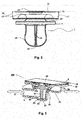
- Fig. 2 shows a schematic side view of a partially sectioned valve insert 1 of a disclosed valve device 100.
- the valve insert 1 has a first sealing device, for example in the form of an elastic sealing ring 31, a bending ring area 33, and a guide device, for example in the form of guide ribs 45. Furthermore, a static valve seat 35, an elastic seat area in the form of an elastic seat area 37, an outer end ring area 39, an inner end ring area 41 and an end stop 43 are shown.
- the elastic sealing ring 31 is on its underside (ie in the illustration of Fig. 2 below) flat, ie flat.
- Fig. 2 shows a deformation space 49, the shape and volume of which can be varied as a function of the valve state of the valve device 100.
- the above-mentioned central area is in exemplary form in Fig. 3 to recognize; there it bears the reference number 44.
- FIG Fig. 2 can be seen, the accumulation of material of the central area 44 z. B. caused by the convergence of guide ribs 45 in an axis of symmetry of the valve insert 1.
- the Figures 3 to 7 show various, exemplarily selected valve states of the valve device 100, which can be achieved by applying a displacement and / or a force, such as, for example, a pressing force on the part of a treatment device or a force of a fluid, to the valve insert 1.
- the valve insert 1 can be switched between the valve states by applying or removing the force.
- Fig. 3 shows a schematically simplified section of the valve device 100 in a valve state, which is referred to below as a sterilization or storage position.
- the valve insert 1 is inserted into the receiving device 3.
- the valve insert 1 rests with its guide ribs 45 on the rigid end part 23 of the lower seat bush 21 of the receiving device 3.
- the valve insert 1 is covered with the film element 5.
- the frictional connection between the guide ribs 45 (cf. Fig. 2 ) and the inner wall of the lower seat bushing 21 of the receiving device 3 is preferably only so large that the valve insert 1 can advantageously be reliably prevented from falling out due to its own weight.
- the bending ring area 33 is preferably designed so that a temporary, for example assembly-related, axial displacement of the end stop 43 of the valve insert 1 to the bottom of the lower seat bushing 21 is advantageously completely reversed by the restoring force of the bending ring area 33.
- the restoring forces of the bending ring area 33 preferably overcome the frictional forces between the guide ribs 45 and the inner walls of the lower seat bushing 21 or guide bushing of the receiving device 3. In this way, particularly simple assembly can be ensured in an advantageous manner.
- valve insert 1 In the in Fig. 3 The sterilization position shown, no external force acts on the valve insert 1.
- the valve insert 1 is therefore essentially not exposed to any pretensioning and / or material stress. All areas of the valve insert 1 that are relevant to the main function are not pressed either with the receiving device 3 or with the housing element 13 (not shown here). They are free from relevant material stresses.
- the valve device 100 is in an open state for a fluid flowing through the valve device 100.
- the fluids can flow bidirectionally through the valve device 100, as shown in FIG Fig. 3 shown double arrows can be seen
- the fluids flow through the valve device 100 through a gap 51 which is located between the elastic sealing ring 31 of the valve insert 1 and the rigid sealing ring 15 of the receiving device 3.
- Such a state is particularly suitable for sterilizing the valve device 100 or for sterilizing an external functional device connected to a valve device 100.
- valve state Since the individual components in such a valve state are tension-free - both with respect to one another and within themselves - this valve state is also preferably suitable for long-term storage of the valve device 100 or an external functional device with such a valve device 100 the affected components do not occur due to a lack of voltage
- the open sterilization position of the valve device 100 now makes it possible to carry out all sterilization or other pretreatments which require the free bidirectional passage of sterilization or treatment fluids, such as blood and / or substituate fluid, through the flow channel 25.
- sterilization or treatment fluids such as blood and / or substituate fluid
- FIG. 11 shows a schematic simplified side view of the valve device 100 from FIG Fig. 3 in a permanently open valve position as the valve state.
- the valve device 100 is in Fig. 4 arranged in a treatment device. This can be seen from the fact that a transmission element 9, for example a pressure actuator of a treatment device, is arranged above the film element 5.
- valve insert 1 is held between the receiving device 3 and the transmission element 9 by means of the guide ribs 45 and above the outer end ring area 39.
- the transmission element 9 can be designed such that the valve insert 1 can be flown through bidirectionally in the permanently open valve position.
- the valve device 100 is therefore in the open position as a result of or controlled by the machine.
- the transmission element 9 rests on the film element 5 in such a way that a closure is achieved between the film element 5 and the outer end ring region 39, unlike in the case of FIG
- Fig. 5 and 6th show schematically simplified side views of the valve device 100 of FIG Fig. 3 and 4th in a valve state of a closed check valve ( Fig. 5 ) or in a valve state of an open check valve ( Fig. 6 ).
- Fig. 5 the installation compression of the valve insert 1 is achieved by shortening a path length (in the axial direction, i.e. in the "from top to bottom” direction in Fig. 5 ) increased between the receiving device 3 and the transmission element 9 and then kept constant.
- a path length in the axial direction, i.e. in the "from top to bottom” direction in Fig. 5
- this can be done simply by inserting the external functional device into the machine.
- active machine arrangements with additional open-close functions of the valve devices 100 this can be done by a corresponding control of the transmission element 9.
- Fig. 5 shows the pretensioned closed valve state of the valve device 100 when a fluid is present on the rigid sealing ring 15 against the flow direction, or when the fluid is present in the flow direction, but the pressure difference between the inflow and outflow side is still smaller than the set minimum response pressure of the check valve.
- the elastic sealing ring 31 and the rigid sealing ring 15 rest on one another or are pressed against one another.
- Fig. 6 shows the valve state during the flow through the valve device 100 in the flow direction.
- the tolerance compensation function described above can take place in the axial direction between the inner end ring area 41 and the end stop 43 and ensures constant functional properties.
- the end stop 43 of the valve insert 1 is already in the check valve position in the stop on the rigid end part 23 of the lower seat bush 21.
- a gap 51 remains between the elastic sealing ring 31 and the rigid sealing ring 15.
- Fig. 7 shows a schematically simplified side view of a valve device 100 in a valve state as a permanently closed valve or as a control valve.
- a control valve can function as a pressure or volume flow control valve.
- the transmission element 9 increases the compression in the axial direction (what is meant is a direction which extends vertically from top to bottom in the figure) by a further piece of axial displacement until the outer end ring area 39 is mechanically compressed with the elastic Sealing ring 31 devices in the axial direction.
- valve device 100 shown can function as a pressure or volume flow control valve.
- the seat area 37 of the valve insert 1, which is elastic in the axial direction, or the elastic sealing ring 31 assigned as a contact partner are designed to be resilient in a defined manner, for example by providing him or her with an additional groove or with resilient thin annular webs or knobs, which in the case of the above further axial deflection of the valve insert 1 result in an intended contact being made between the axial elastic seat area 37 and the elastic sealing ring 31, then in this valve state the valve device 100 can be subject to a defined higher preload.
- Such a higher preload can either be in two discrete steps (gap 51 between the axial elastic seat area 37 and elastic sealing ring 31) before axial actuation and contact after axial actuation or in a continuous manner (initial contact between the named partners) take place depending on the path of the axial displacement of the transmission element 9.
- FIG. 13 shows a side view of an external functional device which is attached to the surface on which FIG Fig. 8 is looked, is provided with a cover device.
- the blood treatment cassette 1000 can at least with the in Fig. 8 to a blood treatment device (in Fig. 1 not shown).
- the blood treatment cassette 1000 has an arterial heparin addition point 63.
- the heparin addition point 63 can also be suitable and provided for the addition of pharmacological active ingredients other than heparin, which are only preferably anticoagulants, or active ingredient combinations. This must always be taken into account even if heparin is mentioned before or below in any context.
- the blood treatment cassette 1000 has a check valve 65 of the arterial heparin addition point 63.
- the check valve 65 is an example of application of the disclosed valve device of the present application.
- the blood treatment cassette 1000 also has a check valve 69 for a venous heparin addition point 67.
- FIG. 10 shows the blood treatment cartridge 1000 of FIG Fig. 8 , wherein the film can be seen on the left edge of the blood treatment cassette 1000 as well as cut out at the top and bottom and opened to the right.
- Fig. 9 shows the elements in the interior of the blood treatment cassette 1000 that can be recognized in greater detail after the film has been cut open.
- Fig. 10 shows the blood treatment cassette 1000 from its rear side. If the blood treatment cassette 1000 is coupled to the blood treatment device, a viewer will look at this rear side when a door of the blood treatment device is opened to remove the blood treatment cassette 1000.
Claims (10)
- Un dispositif fonctionnel externe qui comprend au moins un élément de boîtier (13) ayant au moins un canal d'écoulement (25) ainsi qu'un dispositif de vanne (100), le dispositif fonctionnel externe étant conçu comme une cassette de traitement de fluide médicale, le dispositif de vanne (100) comprenant:- au moins un pointeau (1) élastique dans au moins une section de celui-ci, agencé et conçu de façon à ouvrir et fermer le canal d'écoulement (25), le pointeau (1) comprenant une zone d'anneau de flexion élastique (33), un anneau d'étanchéité (31) en tant que premier dispositif d'étanchéité ainsi qu'un dispositif de guidage,- au moins un dispositif de réception (3) pour le pointeau (1), le dispositif de réception (3) étant prévu dans l'élément de boîtier (13) et comprenant un second dispositif d'étanchéité (15), le pointeau (1) étant agencé dans le dispositif de réception (3) afin d'être compressible en complémentarité de forme et/ou de force contre le second dispositif d'étanchéité (15) par transmission de force et/ou d'empreinte par déplacement sur le pointeau (1) au moyen de l'anneau d'étanchéité élastique (31);où le pointeau (1) est conçu et agencé dans le canal d'écoulement (25) de telle sorte qu'en raison de son élasticité lors de l'empreinte par déplacement et/ou de l'application de force, il soit commutable entre au moins trois états de vanne différents, où dans un état de vanne, aucune force extérieure ou aucune pré-tension ou aucune pré-tension significative n'agit sur le pointeau (1), cet état de vanne correspondant à une position d'écoulement bidirectionnelle au travers du canal d'écoulement (25).
- Le dispositif fonctionnel externe selon la première revendication, où un des autres états de vanne est un état fonctionnel ouvert et/ou un état de vanne anti-retour et/ou un état de vanne de commande ou de régulation et/ou un état de vanne fermé de la vanne et/ou un état de stérilisation.
- Le dispositif fonctionnel externe selon l'une quelconque des revendications précédentes, où le pointeau (1) comprend un matériau élastomère dans au moins une section.
- Le dispositif fonctionnel externe selon l'une quelconque des revendications précédentes, où le pointeau (1) comprend des empreintes dans au moins une section.
- Le dispositif fonctionnel externe selon l'une quelconque des revendications précédentes, où la force exercée sur le pointeau (1) est une force de compression pouvant être initiée par l'installation du dispositif de vanne (100) dans un appareil de traitement.
- Le dispositif fonctionnel externe selon l'une quelconque des revendications précédentes, où l'empreinte par déplacement effectuée sur le pointeau (1) est un décalage pouvant être initié par l'installation du dispositif de vanne (100) dans un appareil de traitement.
- Le dispositif fonctionnel externe selon la revendication 6, où la force de compression ou le décalage peut être transmis par un élément de transmission (9) de l'appareil de traitement.
- Le dispositif fonctionnel externe selon l'une quelconque des revendications précédentes, où le dispositif de vanne (100) est muni d'un dispositif de recouvrement sur au moins une face supérieure.
- Le dispositif fonctionnel externe selon la revendication 8, où le pointeau (1) peut être commuté au moyen d'une force transmise(s) par un appareil de traitement et/ou d'une empreinte par déplacement au travers du dispositif de recouvrement.
- Un appareil de traitement qui comprend au moins un dispositif fonctionnel externe selon une des revendications 1 à 9, où l'appareil de traitement est conçu sous la forme d'un appareil de traitement du sang.
Applications Claiming Priority (5)
| Application Number | Priority Date | Filing Date | Title |
|---|---|---|---|
| DE102009018664A DE102009018664A1 (de) | 2009-04-23 | 2009-04-23 | Externe Funktionseinrichtung, Blutbehandlungsvorrichtung zum Aufnehmen einer erfindungsgemäßen externen Funktionseinrichtung, sowie Verfahren |
| US18560309P | 2009-06-10 | 2009-06-10 | |
| DE102009024469A DE102009024469A1 (de) | 2009-06-10 | 2009-06-10 | Ventilvorrichtung, Ventileinsatz, externe Funktionseinrichtung, Behandlungsvorrichtung sowie Verfahren |
| PCT/EP2010/002295 WO2010121741A1 (fr) | 2009-04-23 | 2010-04-14 | Ensemble soupape, garniture de soupape, dispositif fonctionnel externe, appareil de traitement ainsi que procédés |
| EP10713589.9A EP2421579B1 (fr) | 2009-04-23 | 2010-04-14 | Ensemble soupape, garniture de soupape, dispositif fonctionnel externe, appareil de traitement ainsi que procédés |
Related Parent Applications (2)
| Application Number | Title | Priority Date | Filing Date |
|---|---|---|---|
| EP10713589.9A Division EP2421579B1 (fr) | 2009-04-23 | 2010-04-14 | Ensemble soupape, garniture de soupape, dispositif fonctionnel externe, appareil de traitement ainsi que procédés |
| EP10713589.9A Division-Into EP2421579B1 (fr) | 2009-04-23 | 2010-04-14 | Ensemble soupape, garniture de soupape, dispositif fonctionnel externe, appareil de traitement ainsi que procédés |
Publications (2)
| Publication Number | Publication Date |
|---|---|
| EP3421063A1 EP3421063A1 (fr) | 2019-01-02 |
| EP3421063B1 true EP3421063B1 (fr) | 2021-03-17 |
Family
ID=42992742
Family Applications (2)
| Application Number | Title | Priority Date | Filing Date |
|---|---|---|---|
| EP10713589.9A Active EP2421579B1 (fr) | 2009-04-23 | 2010-04-14 | Ensemble soupape, garniture de soupape, dispositif fonctionnel externe, appareil de traitement ainsi que procédés |
| EP18184410.1A Active EP3421063B1 (fr) | 2009-04-23 | 2010-04-14 | Dispositif fonctionnel externe et dispositif de traitement |
Family Applications Before (1)
| Application Number | Title | Priority Date | Filing Date |
|---|---|---|---|
| EP10713589.9A Active EP2421579B1 (fr) | 2009-04-23 | 2010-04-14 | Ensemble soupape, garniture de soupape, dispositif fonctionnel externe, appareil de traitement ainsi que procédés |
Country Status (6)
| Country | Link |
|---|---|
| US (1) | US9789300B2 (fr) |
| EP (2) | EP2421579B1 (fr) |
| JP (1) | JP5657643B2 (fr) |
| CN (1) | CN102458505B (fr) |
| IN (1) | IN2011KN04779A (fr) |
| WO (1) | WO2010121741A1 (fr) |
Families Citing this family (14)
| Publication number | Priority date | Publication date | Assignee | Title |
|---|---|---|---|---|
| EP3173111B1 (fr) * | 2009-04-23 | 2023-04-12 | Fresenius Medical Care Deutschland GmbH | Dispositif fonctionnel externe et dispositif de traitement de sang avec un dispositif fonctionnel externe selon l'invention |
| US9011370B2 (en) * | 2010-05-13 | 2015-04-21 | Carefusion 303, Inc. | Deformable valve mechanism for controlling fluid delivery |
| WO2014035471A1 (fr) | 2012-08-28 | 2014-03-06 | Fenwal, Inc. | Feuille à ouverture à ressort pour cassette de traitement de fluide |
| US9308362B2 (en) * | 2013-03-12 | 2016-04-12 | Carefusion 303, Inc. | Male luer with fluid path and vent path seals |
| ITMO20130264A1 (it) * | 2013-09-25 | 2015-03-26 | Giuseppe Maffei | Connettore senza ago |
| DE102014102598A1 (de) | 2014-02-27 | 2015-08-27 | Fresenius Medical Care Deutschland Gmbh | Blutbehandlungskassette mit Sterilisationsöffnung und zugehörigem Verschluss sowie Blutbehandlungsvorrichtung |
| DE102014103489A1 (de) * | 2014-03-14 | 2015-09-17 | Fresenius Medical Care Deutschland Gmbh | Rückschlagventilanordnung, medizinische Funktionsvorrichtung und eine Blutbehandlungsvorrichtung |
| DE102014103507A1 (de) * | 2014-03-14 | 2015-09-17 | Fresenius Medical Care Deutschland Gmbh | Medizinische Funktionsvorrichtung mit einem Ventilsitz für ein remanentes Rückschlagventil |
| DE102014103508B4 (de) * | 2014-03-14 | 2019-04-18 | Fresenius Medical Care Deutschland Gmbh | Vorgespanntes Ventil für medizinische Funktionsvorrichtung, und medizinische Funktionsvorrichtung |
| DE102014103491A1 (de) * | 2014-03-14 | 2015-09-17 | Fresenius Medical Care Deutschland Gmbh | Blutbehandlungskassette mit Folienventil und unelastischem Abstandhalter sowie Blutbehandlungsvorrichtung |
| RU2675740C2 (ru) * | 2014-09-10 | 2018-12-24 | Цито365 Аб | Клапан для введения нескольких жидких лекарственных средств |
| WO2016057981A1 (fr) | 2014-10-10 | 2016-04-14 | Nxstage Medical, Inc. | Dispositifs, procédés et systèmes de pince de serrage |
| CA200230S (en) * | 2020-07-01 | 2022-12-07 | Otsuka Pharma Factory Inc | Medicine administration device |
| USD973199S1 (en) * | 2020-07-01 | 2022-12-20 | Otsuka Pharmaceutical Factory, Inc. | Medicine administration device |
Family Cites Families (59)
| Publication number | Priority date | Publication date | Assignee | Title |
|---|---|---|---|---|
| US3889710A (en) * | 1972-11-07 | 1975-06-17 | Julien H Brost | Check valve with elastomeric valve element |
| US3941149A (en) * | 1974-11-11 | 1976-03-02 | Baxter Laboratories, Inc. | Valve |
| US5088515A (en) * | 1989-05-01 | 1992-02-18 | Kamen Dean L | Valve system with removable fluid interface |
| DE3681158D1 (de) * | 1986-04-11 | 1991-10-02 | Braun Melsungen Ag | Injektions-absperrventil. |
| US4712583A (en) * | 1986-05-27 | 1987-12-15 | Pacesetter Infusion, Ltd. | Precision passive flat-top valve for medication infusion system |
| US4815705A (en) * | 1986-11-27 | 1989-03-28 | Toyoda Gosei Co., Ltd. | Valve body |
| JPS63135670A (ja) * | 1986-11-27 | 1988-06-08 | Toyoda Gosei Co Ltd | 弁体 |
| US5186431A (en) * | 1989-09-22 | 1993-02-16 | Yehuda Tamari | Pressure sensitive valves for extracorporeal circuits |
| US4946448A (en) * | 1989-10-23 | 1990-08-07 | Kendall Mcgaw Laboratories, Inc. | Check valve for use with intravenous pump |
| IT1250529B (it) * | 1991-12-13 | 1995-04-08 | Hospal Dasco Spa | Raccordo di campionamento e di infusione per una linea di circolazione extracorporea di sangue. |
| US5462256A (en) * | 1994-05-13 | 1995-10-31 | Abbott Laboratories | Push button flow stop useable with a disposable infusion pumping chamber cassette |
| US5776118A (en) * | 1995-12-13 | 1998-07-07 | Steris Corporation | Medical and biological fluid collection and disposal system |
| US5738644A (en) * | 1995-06-07 | 1998-04-14 | Cobe Laboratories, Inc. | Extracorporeal blood processing methods and apparatus |
| US5775671A (en) * | 1996-06-13 | 1998-07-07 | Nypro Inc. | Luer-activated valve |
| US6638478B1 (en) * | 1997-02-14 | 2003-10-28 | Nxstage Medical, Inc. | Synchronized volumetric fluid balancing systems and methods |
| US6638477B1 (en) * | 1997-02-14 | 2003-10-28 | Nxstage Medical, Inc. | Fluid replacement systems and methods for use in hemofiltration |
| US6595943B1 (en) * | 1997-02-14 | 2003-07-22 | Nxstage Medical, Inc. | Systems and methods for controlling blood flow and waste fluid removal during hemofiltration |
| US6852090B2 (en) * | 1997-02-14 | 2005-02-08 | Nxstage Medical, Inc. | Fluid processing systems and methods using extracorporeal fluid flow panels oriented within a cartridge |
| US6830553B1 (en) * | 1997-02-14 | 2004-12-14 | Nxstage Medical, Inc. | Blood treatment systems and methods that maintain sterile extracorporeal processing conditions |
| US6554789B1 (en) * | 1997-02-14 | 2003-04-29 | Nxstage Medical, Inc. | Layered fluid circuit assemblies and methods for making them |
| AU3273101A (en) * | 1997-02-14 | 2001-06-04 | Nxstage Medical, Inc. | Extracorporeal circuits for performing hemofiltration employing pressure sensingwithout an air interface |
| US6589482B1 (en) * | 1997-02-14 | 2003-07-08 | Nxstage Medical, Inc. | Extracorporeal circuits for performing hemofiltration employing pressure sensing without an air interface |
| US20040243047A1 (en) * | 1997-02-14 | 2004-12-02 | Brugger James M. | Single step fluid circuit engagement device and method |
| US6200287B1 (en) * | 1997-09-05 | 2001-03-13 | Gambro, Inc. | Extracorporeal blood processing methods and apparatus |
| US20060178612A9 (en) * | 1999-09-03 | 2006-08-10 | Baxter International Inc. | Blood processing systems with fluid flow cassette with a pressure actuated pump chamber and in-line air trap |
| JP4203930B2 (ja) | 1999-11-05 | 2009-01-07 | 大下産業株式会社 | 流路切換弁 |
| IT1311347B1 (it) * | 1999-11-12 | 2002-03-12 | Borla Ind | Valvola di ritegno per linee medicali di infusione e simili. |
| EP1099456B1 (fr) * | 1999-11-12 | 2003-02-05 | Industrie Borla SpA | Clapet antiretour pour des lignes de perfusion et similaires |
| US7169352B1 (en) * | 1999-12-22 | 2007-01-30 | Gambro, Inc. | Extracorporeal blood processing methods and apparatus |
| JP4357067B2 (ja) | 2000-03-03 | 2009-11-04 | シエーリング アクチエンゲゼルシャフト | コネクター |
| IT1318743B1 (it) * | 2000-08-08 | 2003-09-10 | Dideco Spa | Unita' pompante pulsatile per fluido, particolarmente sangue. |
| DE10053441B4 (de) | 2000-10-27 | 2004-04-15 | Fresenius Medical Care Deutschland Gmbh | Disposablekassette mit Dichtungsmembran sowie Ventilaktor hierfür |
| US20050020960A1 (en) * | 2001-05-24 | 2005-01-27 | Brugger James M. | Blood treatment cartridge and blood processing machine with slot |
| US20080154214A1 (en) * | 2006-12-22 | 2008-06-26 | Medrad, Inc. | Flow Based Pressure Isolation and Fluid Delivery System Including Flow Based Pressure Isolation |
| US20070161970A1 (en) * | 2004-04-16 | 2007-07-12 | Medrad, Inc. | Fluid Delivery System, Fluid Path Set, and Pressure Isolation Mechanism with Hemodynamic Pressure Dampening Correction |
| CA2469545C (fr) * | 2001-12-07 | 2016-08-30 | Robert F. Wilson | Dispositifs de mesure de basses pressions dans des environnements sous hautes pressions |
| US7153286B2 (en) * | 2002-05-24 | 2006-12-26 | Baxter International Inc. | Automated dialysis system |
| US7238164B2 (en) * | 2002-07-19 | 2007-07-03 | Baxter International Inc. | Systems, methods and apparatuses for pumping cassette-based therapies |
| ES2428031T3 (es) * | 2003-08-12 | 2013-11-05 | Becton, Dickinson And Company | Dispositivo de infusión a modo de parche |
| US8038639B2 (en) * | 2004-11-04 | 2011-10-18 | Baxter International Inc. | Medical fluid system with flexible sheeting disposable unit |
| JP4208820B2 (ja) * | 2003-11-28 | 2009-01-14 | 株式会社東芝 | 核酸検出カセット |
| US20050209563A1 (en) * | 2004-03-19 | 2005-09-22 | Peter Hopping | Cassette-based dialysis medical fluid therapy systems, apparatuses and methods |
| US7243676B2 (en) * | 2004-05-19 | 2007-07-17 | Vernay Laboratories, Inc. | Combination umbrella and inverted bi-directional valve |
| US7462170B2 (en) | 2004-05-25 | 2008-12-09 | Covidien Ag | Administration feeding set and valve mechanism |
| US7201187B2 (en) * | 2004-07-23 | 2007-04-10 | Rain Bird Corporation | Low-flow valve |
| US7296782B2 (en) * | 2004-10-01 | 2007-11-20 | Halkey-Roberts Corporation | Dome check valve |
| US7503902B2 (en) * | 2004-10-07 | 2009-03-17 | Fresenius Medical Care Holdings, Inc. | Blood flow reversal valves and related systems and methods |
| ITTO20040830A1 (it) * | 2004-11-24 | 2005-02-24 | Borla Ind | Componente di flusso per linee medicali di infusione/trasfusione |
| US20060189926A1 (en) * | 2005-02-14 | 2006-08-24 | Hall W D | Apparatus and methods for analyzing body fluid samples |
| CA2606454C (fr) * | 2005-04-27 | 2014-02-11 | Radiant Medical, Inc. | Dispositif et procede pour realiser un transfert de chaleur ameliore depuis un corps |
| US8197231B2 (en) * | 2005-07-13 | 2012-06-12 | Purity Solutions Llc | Diaphragm pump and related methods |
| US20070179435A1 (en) * | 2005-12-21 | 2007-08-02 | Braig James R | Analyte detection system with periodic sample draw and body fluid analyzer |
| JP2007117210A (ja) | 2005-10-25 | 2007-05-17 | Asahi Kinzoku Seisakusho:Kk | 混注管および弁装置 |
| US7981090B2 (en) * | 2006-10-18 | 2011-07-19 | Baxter International Inc. | Luer activated device |
| ITTO20070023A1 (it) | 2007-01-17 | 2008-07-18 | Borla Ind | Valvola unidirezionale per linee medicali di infusione e simili |
| US20080185062A1 (en) * | 2007-02-05 | 2008-08-07 | Johannes Nijland Peter Lodewij | Fluid control valve |
| DE102009012633A1 (de) | 2009-03-10 | 2010-09-23 | Fresenius Medical Care Deutschland Gmbh | Vorrichtung zum Verbinden einer externen Funktionseinrichtung mit einer Anordnung, Anordnung aufweisend eine solche Vorrichtung und Verfahren zum Verbinden |
| DE102009012632A1 (de) | 2009-03-10 | 2010-09-23 | Fresenius Medical Care Deutschland Gmbh | Abdichtungseinrichtung zum Abdichten eines Volumens einer medizinischen Behandlungsanordnung gegen ein weiteres Volumen sowie Anordnung und Verfahren |
| DE102009018664A1 (de) | 2009-04-23 | 2010-10-28 | Fresenius Medical Care Deutschland Gmbh | Externe Funktionseinrichtung, Blutbehandlungsvorrichtung zum Aufnehmen einer erfindungsgemäßen externen Funktionseinrichtung, sowie Verfahren |
-
2010
- 2010-04-14 EP EP10713589.9A patent/EP2421579B1/fr active Active
- 2010-04-14 JP JP2012506375A patent/JP5657643B2/ja active Active
- 2010-04-14 CN CN201080027670.2A patent/CN102458505B/zh active Active
- 2010-04-14 WO PCT/EP2010/002295 patent/WO2010121741A1/fr active Application Filing
- 2010-04-14 EP EP18184410.1A patent/EP3421063B1/fr active Active
- 2010-04-23 US US12/766,266 patent/US9789300B2/en active Active
-
2011
- 2011-11-21 IN IN4779KON2011 patent/IN2011KN04779A/en unknown
Non-Patent Citations (1)
| Title |
|---|
| None * |
Also Published As
| Publication number | Publication date |
|---|---|
| CN102458505A (zh) | 2012-05-16 |
| US9789300B2 (en) | 2017-10-17 |
| WO2010121741A1 (fr) | 2010-10-28 |
| JP2012524558A (ja) | 2012-10-18 |
| CN102458505B (zh) | 2016-05-11 |
| US20100274169A1 (en) | 2010-10-28 |
| EP2421579A1 (fr) | 2012-02-29 |
| EP3421063A1 (fr) | 2019-01-02 |
| IN2011KN04779A (fr) | 2015-06-12 |
| JP5657643B2 (ja) | 2015-01-21 |
| EP2421579B1 (fr) | 2018-10-10 |
Similar Documents
| Publication | Publication Date | Title |
|---|---|---|
| EP3421063B1 (fr) | Dispositif fonctionnel externe et dispositif de traitement | |
| DE102009024469A1 (de) | Ventilvorrichtung, Ventileinsatz, externe Funktionseinrichtung, Behandlungsvorrichtung sowie Verfahren | |
| EP2454506B1 (fr) | Soupape à voies multiples et son procédé de fabrication | |
| DE102009005874A1 (de) | Ventil, insbesondere für ein Bauelement der Mikrofluidtechnik | |
| EP3116590A1 (fr) | Dispositif fonctionnel médical équipé d'un siège de valve pour une valve antiretour rémanente | |
| EP1979038A1 (fr) | Clapet unidirectionnel, en particulier clapet antiretour basse pression, destiné à être utilisé dans le domaine de la technique médicale | |
| EP2710972B1 (fr) | Corps de vanne rotatif pour dispositif d'extraction pour ciments osseux | |
| EP3088019B1 (fr) | Dispositif destine a transmettre un fluide | |
| DE102009024467B4 (de) | Einrichtung sowie externe Funktionseinrichtung und Behandlungsvorrichtung zum Behandeln von medizinischen Fluiden | |
| WO2007009808A1 (fr) | Soupape destinee a un fluide, destinee en particulier a etre utilisee dans une pompe a liquide a fonctionnement mecanique | |
| DE102019211941B3 (de) | Mikrostrukturierte fluidflussregelvorrichtung | |
| EP2873465A1 (fr) | Piston pour distribuer un fluide d'une cartouche | |
| DE102014103508B4 (de) | Vorgespanntes Ventil für medizinische Funktionsvorrichtung, und medizinische Funktionsvorrichtung | |
| EP2421583B1 (fr) | Dispositif, dispositif fonctionnel externe ainsi qu'appareil de traitement pour le traitement de fluides médicaux | |
| EP3030282B1 (fr) | Module de type cartouche | |
| DE102015113164B4 (de) | Fluidisches Steuerelement | |
| DE102008056751A1 (de) | Fluidikvorrichtung mit normal-geschlossener Durchlassöffnung | |
| DE102006044722B4 (de) | Zwei-Wege-Ventil | |
| WO1980002506A1 (fr) | Aiguille pour un dispositif de perfusion | |
| DE19645725C1 (de) | Implantierbares und steuerbares Ventil für medizinische Anwendungen | |
| DE10216220A1 (de) | Unterdruckventil | |
| EP2885035B1 (fr) | Système de valve unidirectionnelle | |
| EP1181471B1 (fr) | Unite d'obturation pour une soupape aseptique a double siege | |
| EP3386582B1 (fr) | Clapet d'arrêt et/ou d'étranglement et appareil de traitement sanguin comportant un tel clapet | |
| DE102018124467A1 (de) | Hydraulisches Mikroventil |
Legal Events
| Date | Code | Title | Description |
|---|---|---|---|
| PUAI | Public reference made under article 153(3) epc to a published international application that has entered the european phase |
Free format text: ORIGINAL CODE: 0009012 |
|
| STAA | Information on the status of an ep patent application or granted ep patent |
Free format text: STATUS: THE APPLICATION HAS BEEN PUBLISHED |
|
| AC | Divisional application: reference to earlier application |
Ref document number: 2421579 Country of ref document: EP Kind code of ref document: P |
|
| AK | Designated contracting states |
Kind code of ref document: A1 Designated state(s): AT BE BG CH CY CZ DE DK EE ES FI FR GB GR HR HU IE IS IT LI LT LU LV MC MK MT NL NO PL PT RO SE SI SK SM TR |
|
| STAA | Information on the status of an ep patent application or granted ep patent |
Free format text: STATUS: REQUEST FOR EXAMINATION WAS MADE |
|
| 17P | Request for examination filed |
Effective date: 20190627 |
|
| RBV | Designated contracting states (corrected) |
Designated state(s): AT BE BG CH CY CZ DE DK EE ES FI FR GB GR HR HU IE IS IT LI LT LU LV MC MK MT NL NO PL PT RO SE SI SK SM TR |
|
| STAA | Information on the status of an ep patent application or granted ep patent |
Free format text: STATUS: EXAMINATION IS IN PROGRESS |
|
| 17Q | First examination report despatched |
Effective date: 20190906 |
|
| GRAP | Despatch of communication of intention to grant a patent |
Free format text: ORIGINAL CODE: EPIDOSNIGR1 |
|
| STAA | Information on the status of an ep patent application or granted ep patent |
Free format text: STATUS: GRANT OF PATENT IS INTENDED |
|
| INTG | Intention to grant announced |
Effective date: 20200514 |
|
| GRAJ | Information related to disapproval of communication of intention to grant by the applicant or resumption of examination proceedings by the epo deleted |
Free format text: ORIGINAL CODE: EPIDOSDIGR1 |
|
| GRAL | Information related to payment of fee for publishing/printing deleted |
Free format text: ORIGINAL CODE: EPIDOSDIGR3 |
|
| GRAS | Grant fee paid |
Free format text: ORIGINAL CODE: EPIDOSNIGR3 |
|
| STAA | Information on the status of an ep patent application or granted ep patent |
Free format text: STATUS: EXAMINATION IS IN PROGRESS |
|
| GRAP | Despatch of communication of intention to grant a patent |
Free format text: ORIGINAL CODE: EPIDOSNIGR1 |
|
| STAA | Information on the status of an ep patent application or granted ep patent |
Free format text: STATUS: GRANT OF PATENT IS INTENDED |
|
| INTC | Intention to grant announced (deleted) | ||
| INTG | Intention to grant announced |
Effective date: 20201007 |
|
| GRAA | (expected) grant |
Free format text: ORIGINAL CODE: 0009210 |
|
| STAA | Information on the status of an ep patent application or granted ep patent |
Free format text: STATUS: THE PATENT HAS BEEN GRANTED |
|
| AC | Divisional application: reference to earlier application |
Ref document number: 2421579 Country of ref document: EP Kind code of ref document: P |
|
| AK | Designated contracting states |
Kind code of ref document: B1 Designated state(s): AT BE BG CH CY CZ DE DK EE ES FI FR GB GR HR HU IE IS IT LI LT LU LV MC MK MT NL NO PL PT RO SE SI SK SM TR |
|
| REG | Reference to a national code |
Ref country code: GB Ref legal event code: FG4D Free format text: NOT ENGLISH |
|
| REG | Reference to a national code |
Ref country code: CH Ref legal event code: EP |
|
| REG | Reference to a national code |
Ref country code: DE Ref legal event code: R096 Ref document number: 502010016876 Country of ref document: DE |
|
| REG | Reference to a national code |
Ref country code: IE Ref legal event code: FG4D Free format text: LANGUAGE OF EP DOCUMENT: GERMAN |
|
| REG | Reference to a national code |
Ref country code: AT Ref legal event code: REF Ref document number: 1371646 Country of ref document: AT Kind code of ref document: T Effective date: 20210415 |
|
| REG | Reference to a national code |
Ref country code: LT Ref legal event code: MG9D |
|
| PG25 | Lapsed in a contracting state [announced via postgrant information from national office to epo] |
Ref country code: FI Free format text: LAPSE BECAUSE OF FAILURE TO SUBMIT A TRANSLATION OF THE DESCRIPTION OR TO PAY THE FEE WITHIN THE PRESCRIBED TIME-LIMIT Effective date: 20210317 Ref country code: HR Free format text: LAPSE BECAUSE OF FAILURE TO SUBMIT A TRANSLATION OF THE DESCRIPTION OR TO PAY THE FEE WITHIN THE PRESCRIBED TIME-LIMIT Effective date: 20210317 Ref country code: GR Free format text: LAPSE BECAUSE OF FAILURE TO SUBMIT A TRANSLATION OF THE DESCRIPTION OR TO PAY THE FEE WITHIN THE PRESCRIBED TIME-LIMIT Effective date: 20210618 Ref country code: BG Free format text: LAPSE BECAUSE OF FAILURE TO SUBMIT A TRANSLATION OF THE DESCRIPTION OR TO PAY THE FEE WITHIN THE PRESCRIBED TIME-LIMIT Effective date: 20210617 Ref country code: NO Free format text: LAPSE BECAUSE OF FAILURE TO SUBMIT A TRANSLATION OF THE DESCRIPTION OR TO PAY THE FEE WITHIN THE PRESCRIBED TIME-LIMIT Effective date: 20210617 |
|
| REG | Reference to a national code |
Ref country code: NL Ref legal event code: MP Effective date: 20210317 |
|
| PG25 | Lapsed in a contracting state [announced via postgrant information from national office to epo] |
Ref country code: SE Free format text: LAPSE BECAUSE OF FAILURE TO SUBMIT A TRANSLATION OF THE DESCRIPTION OR TO PAY THE FEE WITHIN THE PRESCRIBED TIME-LIMIT Effective date: 20210317 Ref country code: LV Free format text: LAPSE BECAUSE OF FAILURE TO SUBMIT A TRANSLATION OF THE DESCRIPTION OR TO PAY THE FEE WITHIN THE PRESCRIBED TIME-LIMIT Effective date: 20210317 |
|
| PG25 | Lapsed in a contracting state [announced via postgrant information from national office to epo] |
Ref country code: NL Free format text: LAPSE BECAUSE OF FAILURE TO SUBMIT A TRANSLATION OF THE DESCRIPTION OR TO PAY THE FEE WITHIN THE PRESCRIBED TIME-LIMIT Effective date: 20210317 |
|
| PG25 | Lapsed in a contracting state [announced via postgrant information from national office to epo] |
Ref country code: SM Free format text: LAPSE BECAUSE OF FAILURE TO SUBMIT A TRANSLATION OF THE DESCRIPTION OR TO PAY THE FEE WITHIN THE PRESCRIBED TIME-LIMIT Effective date: 20210317 Ref country code: EE Free format text: LAPSE BECAUSE OF FAILURE TO SUBMIT A TRANSLATION OF THE DESCRIPTION OR TO PAY THE FEE WITHIN THE PRESCRIBED TIME-LIMIT Effective date: 20210317 Ref country code: CZ Free format text: LAPSE BECAUSE OF FAILURE TO SUBMIT A TRANSLATION OF THE DESCRIPTION OR TO PAY THE FEE WITHIN THE PRESCRIBED TIME-LIMIT Effective date: 20210317 Ref country code: LT Free format text: LAPSE BECAUSE OF FAILURE TO SUBMIT A TRANSLATION OF THE DESCRIPTION OR TO PAY THE FEE WITHIN THE PRESCRIBED TIME-LIMIT Effective date: 20210317 |
|
| PG25 | Lapsed in a contracting state [announced via postgrant information from national office to epo] |
Ref country code: PT Free format text: LAPSE BECAUSE OF FAILURE TO SUBMIT A TRANSLATION OF THE DESCRIPTION OR TO PAY THE FEE WITHIN THE PRESCRIBED TIME-LIMIT Effective date: 20210719 Ref country code: PL Free format text: LAPSE BECAUSE OF FAILURE TO SUBMIT A TRANSLATION OF THE DESCRIPTION OR TO PAY THE FEE WITHIN THE PRESCRIBED TIME-LIMIT Effective date: 20210317 Ref country code: RO Free format text: LAPSE BECAUSE OF FAILURE TO SUBMIT A TRANSLATION OF THE DESCRIPTION OR TO PAY THE FEE WITHIN THE PRESCRIBED TIME-LIMIT Effective date: 20210317 Ref country code: SK Free format text: LAPSE BECAUSE OF FAILURE TO SUBMIT A TRANSLATION OF THE DESCRIPTION OR TO PAY THE FEE WITHIN THE PRESCRIBED TIME-LIMIT Effective date: 20210317 Ref country code: IS Free format text: LAPSE BECAUSE OF FAILURE TO SUBMIT A TRANSLATION OF THE DESCRIPTION OR TO PAY THE FEE WITHIN THE PRESCRIBED TIME-LIMIT Effective date: 20210717 |
|
| REG | Reference to a national code |
Ref country code: DE Ref legal event code: R097 Ref document number: 502010016876 Country of ref document: DE |
|
| PG25 | Lapsed in a contracting state [announced via postgrant information from national office to epo] |
Ref country code: LU Free format text: LAPSE BECAUSE OF NON-PAYMENT OF DUE FEES Effective date: 20210414 |
|
| REG | Reference to a national code |
Ref country code: BE Ref legal event code: MM Effective date: 20210430 |
|
| PLBE | No opposition filed within time limit |
Free format text: ORIGINAL CODE: 0009261 |
|
| STAA | Information on the status of an ep patent application or granted ep patent |
Free format text: STATUS: NO OPPOSITION FILED WITHIN TIME LIMIT |
|
| PG25 | Lapsed in a contracting state [announced via postgrant information from national office to epo] |
Ref country code: ES Free format text: LAPSE BECAUSE OF FAILURE TO SUBMIT A TRANSLATION OF THE DESCRIPTION OR TO PAY THE FEE WITHIN THE PRESCRIBED TIME-LIMIT Effective date: 20210317 Ref country code: DK Free format text: LAPSE BECAUSE OF FAILURE TO SUBMIT A TRANSLATION OF THE DESCRIPTION OR TO PAY THE FEE WITHIN THE PRESCRIBED TIME-LIMIT Effective date: 20210317 Ref country code: CH Free format text: LAPSE BECAUSE OF NON-PAYMENT OF DUE FEES Effective date: 20210430 Ref country code: MC Free format text: LAPSE BECAUSE OF FAILURE TO SUBMIT A TRANSLATION OF THE DESCRIPTION OR TO PAY THE FEE WITHIN THE PRESCRIBED TIME-LIMIT Effective date: 20210317 Ref country code: LI Free format text: LAPSE BECAUSE OF NON-PAYMENT OF DUE FEES Effective date: 20210430 |
|
| 26N | No opposition filed |
Effective date: 20211220 |
|
| PG25 | Lapsed in a contracting state [announced via postgrant information from national office to epo] |
Ref country code: SI Free format text: LAPSE BECAUSE OF FAILURE TO SUBMIT A TRANSLATION OF THE DESCRIPTION OR TO PAY THE FEE WITHIN THE PRESCRIBED TIME-LIMIT Effective date: 20210317 |
|
| PG25 | Lapsed in a contracting state [announced via postgrant information from national office to epo] |
Ref country code: IT Free format text: LAPSE BECAUSE OF FAILURE TO SUBMIT A TRANSLATION OF THE DESCRIPTION OR TO PAY THE FEE WITHIN THE PRESCRIBED TIME-LIMIT Effective date: 20210317 Ref country code: IE Free format text: LAPSE BECAUSE OF NON-PAYMENT OF DUE FEES Effective date: 20210414 |
|
| PG25 | Lapsed in a contracting state [announced via postgrant information from national office to epo] |
Ref country code: IS Free format text: LAPSE BECAUSE OF FAILURE TO SUBMIT A TRANSLATION OF THE DESCRIPTION OR TO PAY THE FEE WITHIN THE PRESCRIBED TIME-LIMIT Effective date: 20210717 |
|
| REG | Reference to a national code |
Ref country code: AT Ref legal event code: MM01 Ref document number: 1371646 Country of ref document: AT Kind code of ref document: T Effective date: 20210414 |
|
| PG25 | Lapsed in a contracting state [announced via postgrant information from national office to epo] |
Ref country code: BE Free format text: LAPSE BECAUSE OF NON-PAYMENT OF DUE FEES Effective date: 20210430 |
|
| PG25 | Lapsed in a contracting state [announced via postgrant information from national office to epo] |
Ref country code: AT Free format text: LAPSE BECAUSE OF NON-PAYMENT OF DUE FEES Effective date: 20210414 |
|
| PGFP | Annual fee paid to national office [announced via postgrant information from national office to epo] |
Ref country code: FR Payment date: 20230321 Year of fee payment: 14 |
|
| PG25 | Lapsed in a contracting state [announced via postgrant information from national office to epo] |
Ref country code: CY Free format text: LAPSE BECAUSE OF FAILURE TO SUBMIT A TRANSLATION OF THE DESCRIPTION OR TO PAY THE FEE WITHIN THE PRESCRIBED TIME-LIMIT Effective date: 20210317 |
|
| PGFP | Annual fee paid to national office [announced via postgrant information from national office to epo] |
Ref country code: GB Payment date: 20230321 Year of fee payment: 14 |
|
| P01 | Opt-out of the competence of the unified patent court (upc) registered |
Effective date: 20230602 |
|
| PG25 | Lapsed in a contracting state [announced via postgrant information from national office to epo] |
Ref country code: HU Free format text: LAPSE BECAUSE OF FAILURE TO SUBMIT A TRANSLATION OF THE DESCRIPTION OR TO PAY THE FEE WITHIN THE PRESCRIBED TIME-LIMIT; INVALID AB INITIO Effective date: 20100414 |
|
| PGFP | Annual fee paid to national office [announced via postgrant information from national office to epo] |
Ref country code: DE Payment date: 20230321 Year of fee payment: 14 |